EP2133975A2 - Method and system for determining and charging Li-ion battery in an integrated power system - Google Patents
Method and system for determining and charging Li-ion battery in an integrated power system Download PDFInfo
- Publication number
- EP2133975A2 EP2133975A2 EP20090162298 EP09162298A EP2133975A2 EP 2133975 A2 EP2133975 A2 EP 2133975A2 EP 20090162298 EP20090162298 EP 20090162298 EP 09162298 A EP09162298 A EP 09162298A EP 2133975 A2 EP2133975 A2 EP 2133975A2
- Authority
- EP
- European Patent Office
- Prior art keywords
- battery
- bus
- charging
- generator
- converter
- Prior art date
- Legal status (The legal status is an assumption and is not a legal conclusion. Google has not performed a legal analysis and makes no representation as to the accuracy of the status listed.)
- Granted
Links
Images

Classifications
-
- H—ELECTRICITY
- H02—GENERATION; CONVERSION OR DISTRIBUTION OF ELECTRIC POWER
- H02J—ELECTRIC POWER NETWORKS; CIRCUIT ARRANGEMENTS OR SYSTEMS FOR SUPPLYING OR DISTRIBUTING ELECTRIC POWER; SYSTEMS FOR STORING ELECTRIC ENERGY
- H02J7/00—Circuit arrangements for charging or discharging batteries or for supplying loads from batteries
- H02J7/34—Parallel operation in networks using both storage and other DC sources, e.g. providing buffering
-
- B—PERFORMING OPERATIONS; TRANSPORTING
- B60—VEHICLES IN GENERAL
- B60L—PROPULSION OF ELECTRICALLY-PROPELLED VEHICLES; SUPPLYING ELECTRIC POWER FOR AUXILIARY EQUIPMENT OF ELECTRICALLY-PROPELLED VEHICLES; ELECTRODYNAMIC BRAKE SYSTEMS FOR VEHICLES IN GENERAL; MAGNETIC SUSPENSION OR LEVITATION FOR VEHICLES; MONITORING OPERATING VARIABLES OF ELECTRICALLY-PROPELLED VEHICLES; ELECTRIC SAFETY DEVICES FOR ELECTRICALLY-PROPELLED VEHICLES
- B60L3/00—Electric devices on electrically-propelled vehicles for safety purposes; Monitoring operating variables, e.g. speed, deceleration or energy consumption
- B60L3/0023—Detecting, eliminating, remedying or compensating for drive train abnormalities, e.g. failures within the drive train
- B60L3/0046—Detecting, eliminating, remedying or compensating for drive train abnormalities, e.g. failures within the drive train relating to electric energy storage systems, e.g. batteries or capacitors
-
- B—PERFORMING OPERATIONS; TRANSPORTING
- B60—VEHICLES IN GENERAL
- B60L—PROPULSION OF ELECTRICALLY-PROPELLED VEHICLES; SUPPLYING ELECTRIC POWER FOR AUXILIARY EQUIPMENT OF ELECTRICALLY-PROPELLED VEHICLES; ELECTRODYNAMIC BRAKE SYSTEMS FOR VEHICLES IN GENERAL; MAGNETIC SUSPENSION OR LEVITATION FOR VEHICLES; MONITORING OPERATING VARIABLES OF ELECTRICALLY-PROPELLED VEHICLES; ELECTRIC SAFETY DEVICES FOR ELECTRICALLY-PROPELLED VEHICLES
- B60L58/00—Methods or circuit arrangements for monitoring or controlling batteries or fuel cells, specially adapted for electric vehicles
- B60L58/10—Methods or circuit arrangements for monitoring or controlling batteries or fuel cells, specially adapted for electric vehicles for monitoring or controlling batteries
- B60L58/12—Methods or circuit arrangements for monitoring or controlling batteries or fuel cells, specially adapted for electric vehicles for monitoring or controlling batteries responding to state of charge [SoC]
- B60L58/15—Preventing overcharging
-
- B—PERFORMING OPERATIONS; TRANSPORTING
- B60—VEHICLES IN GENERAL
- B60L—PROPULSION OF ELECTRICALLY-PROPELLED VEHICLES; SUPPLYING ELECTRIC POWER FOR AUXILIARY EQUIPMENT OF ELECTRICALLY-PROPELLED VEHICLES; ELECTRODYNAMIC BRAKE SYSTEMS FOR VEHICLES IN GENERAL; MAGNETIC SUSPENSION OR LEVITATION FOR VEHICLES; MONITORING OPERATING VARIABLES OF ELECTRICALLY-PROPELLED VEHICLES; ELECTRIC SAFETY DEVICES FOR ELECTRICALLY-PROPELLED VEHICLES
- B60L58/00—Methods or circuit arrangements for monitoring or controlling batteries or fuel cells, specially adapted for electric vehicles
- B60L58/10—Methods or circuit arrangements for monitoring or controlling batteries or fuel cells, specially adapted for electric vehicles for monitoring or controlling batteries
- B60L58/18—Methods or circuit arrangements for monitoring or controlling batteries or fuel cells, specially adapted for electric vehicles for monitoring or controlling batteries of two or more battery modules
- B60L58/22—Balancing the charge of battery modules
-
- H—ELECTRICITY
- H02—GENERATION; CONVERSION OR DISTRIBUTION OF ELECTRIC POWER
- H02J—ELECTRIC POWER NETWORKS; CIRCUIT ARRANGEMENTS OR SYSTEMS FOR SUPPLYING OR DISTRIBUTING ELECTRIC POWER; SYSTEMS FOR STORING ELECTRIC ENERGY
- H02J7/00—Circuit arrangements for charging or discharging batteries or for supplying loads from batteries
- H02J7/90—Regulation of charging or discharging current or voltage
- H02J7/92—Regulation of charging or discharging current or voltage with prioritisation of loads or sources
-
- B—PERFORMING OPERATIONS; TRANSPORTING
- B60—VEHICLES IN GENERAL
- B60L—PROPULSION OF ELECTRICALLY-PROPELLED VEHICLES; SUPPLYING ELECTRIC POWER FOR AUXILIARY EQUIPMENT OF ELECTRICALLY-PROPELLED VEHICLES; ELECTRODYNAMIC BRAKE SYSTEMS FOR VEHICLES IN GENERAL; MAGNETIC SUSPENSION OR LEVITATION FOR VEHICLES; MONITORING OPERATING VARIABLES OF ELECTRICALLY-PROPELLED VEHICLES; ELECTRIC SAFETY DEVICES FOR ELECTRICALLY-PROPELLED VEHICLES
- B60L2240/00—Control parameters of input or output; Target parameters
- B60L2240/40—Drive Train control parameters
- B60L2240/54—Drive Train control parameters related to batteries
- B60L2240/545—Temperature
-
- B—PERFORMING OPERATIONS; TRANSPORTING
- B60—VEHICLES IN GENERAL
- B60L—PROPULSION OF ELECTRICALLY-PROPELLED VEHICLES; SUPPLYING ELECTRIC POWER FOR AUXILIARY EQUIPMENT OF ELECTRICALLY-PROPELLED VEHICLES; ELECTRODYNAMIC BRAKE SYSTEMS FOR VEHICLES IN GENERAL; MAGNETIC SUSPENSION OR LEVITATION FOR VEHICLES; MONITORING OPERATING VARIABLES OF ELECTRICALLY-PROPELLED VEHICLES; ELECTRIC SAFETY DEVICES FOR ELECTRICALLY-PROPELLED VEHICLES
- B60L2240/00—Control parameters of input or output; Target parameters
- B60L2240/40—Drive Train control parameters
- B60L2240/54—Drive Train control parameters related to batteries
- B60L2240/547—Voltage
-
- B—PERFORMING OPERATIONS; TRANSPORTING
- B60—VEHICLES IN GENERAL
- B60L—PROPULSION OF ELECTRICALLY-PROPELLED VEHICLES; SUPPLYING ELECTRIC POWER FOR AUXILIARY EQUIPMENT OF ELECTRICALLY-PROPELLED VEHICLES; ELECTRODYNAMIC BRAKE SYSTEMS FOR VEHICLES IN GENERAL; MAGNETIC SUSPENSION OR LEVITATION FOR VEHICLES; MONITORING OPERATING VARIABLES OF ELECTRICALLY-PROPELLED VEHICLES; ELECTRIC SAFETY DEVICES FOR ELECTRICALLY-PROPELLED VEHICLES
- B60L2240/00—Control parameters of input or output; Target parameters
- B60L2240/40—Drive Train control parameters
- B60L2240/54—Drive Train control parameters related to batteries
- B60L2240/549—Current
-
- B—PERFORMING OPERATIONS; TRANSPORTING
- B60—VEHICLES IN GENERAL
- B60L—PROPULSION OF ELECTRICALLY-PROPELLED VEHICLES; SUPPLYING ELECTRIC POWER FOR AUXILIARY EQUIPMENT OF ELECTRICALLY-PROPELLED VEHICLES; ELECTRODYNAMIC BRAKE SYSTEMS FOR VEHICLES IN GENERAL; MAGNETIC SUSPENSION OR LEVITATION FOR VEHICLES; MONITORING OPERATING VARIABLES OF ELECTRICALLY-PROPELLED VEHICLES; ELECTRIC SAFETY DEVICES FOR ELECTRICALLY-PROPELLED VEHICLES
- B60L2240/00—Control parameters of input or output; Target parameters
- B60L2240/60—Navigation input
- B60L2240/66—Ambient conditions
- B60L2240/662—Temperature
-
- G—PHYSICS
- G01—MEASURING; TESTING
- G01R—MEASURING ELECTRIC VARIABLES; MEASURING MAGNETIC VARIABLES
- G01R31/00—Arrangements for testing electric properties; Arrangements for locating electric faults; Arrangements for electrical testing characterised by what is being tested not provided for elsewhere
- G01R31/36—Arrangements for testing, measuring or monitoring the electrical condition of accumulators or electric batteries, e.g. capacity or state of charge [SoC]
- G01R31/382—Arrangements for monitoring battery or accumulator variables, e.g. SoC
-
- Y—GENERAL TAGGING OF NEW TECHNOLOGICAL DEVELOPMENTS; GENERAL TAGGING OF CROSS-SECTIONAL TECHNOLOGIES SPANNING OVER SEVERAL SECTIONS OF THE IPC; TECHNICAL SUBJECTS COVERED BY FORMER USPC CROSS-REFERENCE ART COLLECTIONS [XRACs] AND DIGESTS
- Y02—TECHNOLOGIES OR APPLICATIONS FOR MITIGATION OR ADAPTATION AGAINST CLIMATE CHANGE
- Y02T—CLIMATE CHANGE MITIGATION TECHNOLOGIES RELATED TO TRANSPORTATION
- Y02T10/00—Road transport of goods or passengers
- Y02T10/60—Other road transportation technologies with climate change mitigation effect
- Y02T10/70—Energy storage systems for electromobility, e.g. batteries
-
- Y—GENERAL TAGGING OF NEW TECHNOLOGICAL DEVELOPMENTS; GENERAL TAGGING OF CROSS-SECTIONAL TECHNOLOGIES SPANNING OVER SEVERAL SECTIONS OF THE IPC; TECHNICAL SUBJECTS COVERED BY FORMER USPC CROSS-REFERENCE ART COLLECTIONS [XRACs] AND DIGESTS
- Y02—TECHNOLOGIES OR APPLICATIONS FOR MITIGATION OR ADAPTATION AGAINST CLIMATE CHANGE
- Y02T—CLIMATE CHANGE MITIGATION TECHNOLOGIES RELATED TO TRANSPORTATION
- Y02T10/00—Road transport of goods or passengers
- Y02T10/60—Other road transportation technologies with climate change mitigation effect
- Y02T10/72—Electric energy management in electromobility
-
- Y—GENERAL TAGGING OF NEW TECHNOLOGICAL DEVELOPMENTS; GENERAL TAGGING OF CROSS-SECTIONAL TECHNOLOGIES SPANNING OVER SEVERAL SECTIONS OF THE IPC; TECHNICAL SUBJECTS COVERED BY FORMER USPC CROSS-REFERENCE ART COLLECTIONS [XRACs] AND DIGESTS
- Y02—TECHNOLOGIES OR APPLICATIONS FOR MITIGATION OR ADAPTATION AGAINST CLIMATE CHANGE
- Y02T—CLIMATE CHANGE MITIGATION TECHNOLOGIES RELATED TO TRANSPORTATION
- Y02T90/00—Enabling technologies or technologies with a potential or indirect contribution to GHG emissions mitigation
- Y02T90/10—Technologies relating to charging of electric vehicles
- Y02T90/16—Information or communication technologies improving the operation of electric vehicles
Definitions
- the present invention relates to a method and system for determining the state of charge and defining a charging algorithm for lithium ion (Li-ion) batteries and more particularly, to a method and system of determining and charging Li-ion batteries while the batteries remain floating on the direct current (DC) bus without the need for a dedicated charger.
- Li-ion lithium ion
- Lithium Ion batteries integrated in an electrical power system need to be charged in a short time and in a way that guarantees their safe and optimal charging.
- Present methods include charging batteries via dedicated chargers, internal or external to the batteries and the battery envelope or external to the battery.
- Li-lon batteries are an emerging technology in the area of energy storage. Due to their particular chemistry and build, this emerging technology imposes more stringent methods of charging and discharging to ensure that operation safety margins are maintained. In addition, it is necessary to accurately determine the state of charge (SOC) of a Li-lon battery in order to be aware of the reserves of stored energy in the system and to adapt the necessary measures as a result. When at a low SOC, the charging process must be re-started.
- SOC state of charge
- a Li-lon battery should not be charged beyond a certain limit.
- the charging current delivered to a Li-ion should be limited at the commencement of the start of charging and also when the battery approaches fully charge state.
- internal parameters of the battery i.e., cell temperature, voltage, voltage balance between the different cells that constitute the battery, should be monitored and action taken if limits are exceeded.
- an apparatus for monitoring and charging a battery in an integrated power system comprises a battery electrically connected to a DC bus; a DC generator electrically connected to the DC bus; and a converter electrically connected to the DC bus, wherein the battery is charged while floating on the DC bus, and wherein a dedicated battery charger is not required to charge the battery.
- an apparatus for monitoring and charging a battery in an integrated power system comprises an external power source providing a first source of power; a converter connected to said first power source to convert the external power source into a direct current; a direct current bus connected to the converter to receive the first source of power; a direct current generator also connected to the direct current bus providing a second source of power; and a generator control unit connected to the direct current generator to control the second source of power; wherein a charging algorithm used to charge the battery is implemented in the generator control unit or said converter, or both.
- a method for charging a battery in an integrated power system comprises regulating a charging current to a constant predetermined maximum value by decreasing a voltage level on a DC bus; supplying the charging current to the battery until a state of charge of the battery reaches a predetermined value while increasing the voltage level as the internal impedance of the battery increases; reducing the charging current to the battery while maintaining a constant voltage on the DC bus after the state of charge of the battery surpasses the predetermined value; and discontinuing charging of the battery when the charging current decreases to a value of about 1 % of the battery nominal amp-hour capacity.
- Figure 1 shows a battery monitoring and SOC set up, used to determine the SOC of a battery according to an embodiment of the present invention
- Figure 2 shows a graph of the charge characteristics of the SOC versus the terminal voltage
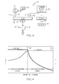
- Figure 3 shows a schematic drawing of a power system used to charge a battery according to an exemplary embodiment of the present invention
- Figure 4 shows a graph of charge characteristic achieved utilizing the system and method according to an exemplary embodiment of the present invention.
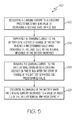
- Figure 5 shows a flow chart describing a method according to an exemplary embodiment of the present invention.
- embodiments of the present invention provide methods of determining the state of charge of a Li-lon battery based on the monitoring of a balance of currents into and out of the battery, the terminals voltage of the battery during charging and discharging, and the terminals voltage of the battery during open circuit, i.e., non connected.
- the results of the above three measurements and monitoring processes are complementary and when taken in conjunction may allow the determination of the state of charge of the battery.
- a current sensor and/or a plurality of current sensors may report the battery current to the computational device housing the algorithms which determine the SOC of the battery.
- the terminal voltage of the battery and temperature information of the battery cells/packs may also reported to the device.
- the computational device may be a microprocessor.
- embodiments of the present invention also provide methods of charging Li-lon batteries serving as energy storage components in a power system.
- the power system may be, for example, incorporated into a ground vehicle.
- the sources for charging the battery may be the main vehicle generator or an auxiliary generator supplying power directly to the DC bus or via conversion equipment.
- the battery In the process of charging a battery from a low state of charge, the battery may absorb a very high current due to its very low internal impedance. This current may reach unsafe values; therefore the current should be limited.
- the charging current should be stopped in order not to overcharge the battery.
- the charging method described below may take advantage of the control system resources in the vehicle as well as of the voltage regulation capabilities built into the generator control units (GCUs) or the conversion units. In this way, the battery may be charged directly while floating on the DC bus fed by either a generator or a converter. This method of charging may not require dedicated chargers. In addition to eliminating the need for dedicated chargers, by having the battery directly floating on the bus, the quality of the power on the bus may be improved.
- GCUs generator control units
- a battery 10 may be connected to a DC bus 12 via a contactor 14.
- a computational device 16 such as a microprocessor, may receive various inputs from the battery 10, such as ambient temperature, battery temperature, and battery voltage.
- a current sensor 18 may send a charge/discharge current measurement signal to the computational device 16.
- the contactor 14 may also send a signal to the computational device 16, the signal depicting the connect status of the battery 10 to the DC bus 12.
- a SOC 20 of the battery 10 may be determined based on information 22 supplied to the computational device 16.
- a graph 24 of the state of charge over the terminal voltage of a battery (e.g., battery 10). This curve may be known for the particular battery being used or may be determined experimentally for any particular battery by methods known in the art. The SOC of the battery may be useful in determining battery charging parameters, as discussed in greater detail below.
- FIG. 3 there is shown a schematic drawing of a power system 30 including a generator 32 which may be controlled by GCU 34 and connected to a DC bus 36 by a contactor 38.
- a generator 32 which may be controlled by GCU 34 and connected to a DC bus 36 by a contactor 38.
- an AC/DC or DC/DC converter 40 may be connected via contactor 42.
- the converter 40 may be powered by an external power source (not shown) or by a vehicle internal source 44 via contactor 46.
- the Li-ion battery 48 may be connected to the DC bus 36 via a contactor (not shown) or directly.
- the DC bus 36 may be powered by the DC generator 32 or by converter 40 or by both, generator 32 and converter 40.
- the generator output voltage may be controlled by the generator control unit 34 and the converter 40 output voltage may be internally controlled.
- the charge current magnitude may be measured by a current sensor 50 and reported to the GCU 34 and converter 40.
- a charging method may be based on the charging current of the battery 48 as measured via the current sensor 50.
- the value of this current may be sensed by the generator control unit 34 if the generator 32 is supplying the DC bus 36, or to the converter 40 that may supply the DC bus 36.
- the GCU 34 and the converter 40 controls may include a control loop (not shown) for the regulation of the current. For example, during commencing of the starting of charging the battery 48, the charging current may be regulated to a predetermined value. This action may be achieved via decreasing the voltage level on the DC bus 36; this action (current limit via voltage control) may be integrated as an independent control loop in the generator GCU or converter circuitry.
- the voltage level on the DC bus 36 may be permitted to be in an allowed range, typically between 22V to 30V for certain ground vehicles. Therefore, if a value of 23V is required to restrain the voltage to obtain a prescribed constant charging current, lowering the voltage level on the DC bus 36 to this level may still be high enough to continue to supply power to the other loads fed from the same DC bus 36. While charging the battery 48 under constant current, due to the fact that the internal impedance of the battery increases in the process, the voltage on the DC bus 36 should be increased. When reaching the nominal value (shown as dotted line 52 in Figure 4 ), the voltage may be controlled to the nominal constant value 54 as required by the DC bus 36 and also compatible with the continuation of the charging process.
- the charging current may decrease. In this way, a constant current - constant voltage charging algorithm may be created.
- the GCU 34 or the converter 40 controls may take action to decrease the output voltage so that the charging current is interrupted.
- safety monitoring related to temperature and balancing of the battery cells may be executed at the battery level.
- the results of the monitoring may be passed to the GCU 34 and the converter 40 so that higher level actions may be taken at this level (i.e., drop voltage, disconnect of battery from the bus, etc.) in order to preserve the battery and its safety of operation
- Figure 4 shows the charge characteristic achieved with the combined control of the generator 34 and/or converter 40 output voltage.
- its internal impedance may be minimal. Therefore, the tendency is that the charge current, without limitations, will rise to very high values. Therefore if the output voltage of the generator 32 is adjusted to a lower value via the GCU 34 or the output value of the converter 40 is adjusted to a lower value via its internal control circuitry, a lower charge current may be achieved.
- the constant current - constant voltage characteristic of Figure 2 can be achieved.
- a charging current may be regulated to a constant predetermined maximum value by decreasing a voltage level on a DC bus (e.g., DC bus 36).
- the charging current may be supplied to the battery until a state of charge of the battery reaches a predetermined value (e.g., nominal value 52) while increasing the voltage level as the internal impedance of the battery increases.
- the charging current to the battery may be reduced while maintaining a constant voltage on the DC bus after the state of charge of the battery surpasses the predetermined value.
- charging of the battery may be discontinued when the charging current decreases to a value of about 1% of the battery nominal amp-hour capacity (or about 1% of the battery's C1 value).
Landscapes
- Engineering & Computer Science (AREA)
- Power Engineering (AREA)
- Life Sciences & Earth Sciences (AREA)
- Sustainable Development (AREA)
- Sustainable Energy (AREA)
- Transportation (AREA)
- Mechanical Engineering (AREA)
- Secondary Cells (AREA)
- Charge And Discharge Circuits For Batteries Or The Like (AREA)
Abstract
Description
- The present application claims benefit of United States Provisional Application No.
61/060,950 filed June 12, 2008 - The present invention relates to a method and system for determining the state of charge and defining a charging algorithm for lithium ion (Li-ion) batteries and more particularly, to a method and system of determining and charging Li-ion batteries while the batteries remain floating on the direct current (DC) bus without the need for a dedicated charger.
- Lithium Ion batteries integrated in an electrical power system need to be charged in a short time and in a way that guarantees their safe and optimal charging. Present methods include charging batteries via dedicated chargers, internal or external to the batteries and the battery envelope or external to the battery.
- Li-lon batteries are an emerging technology in the area of energy storage. Due to their particular chemistry and build, this emerging technology imposes more stringent methods of charging and discharging to ensure that operation safety margins are maintained. In addition, it is necessary to accurately determine the state of charge (SOC) of a Li-lon battery in order to be aware of the reserves of stored energy in the system and to adapt the necessary measures as a result. When at a low SOC, the charging process must be re-started.
- With respect to the charging process, a Li-lon battery should not be charged beyond a certain limit. The charging current delivered to a Li-ion should be limited at the commencement of the start of charging and also when the battery approaches fully charge state. In addition, internal parameters of the battery, i.e., cell temperature, voltage, voltage balance between the different cells that constitute the battery, should be monitored and action taken if limits are exceeded.
- As can be seen, there is a need for a system and method for accurately determining the SOC of a battery and safely charging the battery in an integrated power system.
- In one aspect of the present invention an apparatus for monitoring and charging a battery in an integrated power system, the apparatus comprises a battery electrically connected to a DC bus; a DC generator electrically connected to the DC bus; and a converter electrically connected to the DC bus, wherein the battery is charged while floating on the DC bus, and wherein a dedicated battery charger is not required to charge the battery.
- In another aspect of the present invention, an apparatus for monitoring and charging a battery in an integrated power system comprises an external power source providing a first source of power; a converter connected to said first power source to convert the external power source into a direct current; a direct current bus connected to the converter to receive the first source of power; a direct current generator also connected to the direct current bus providing a second source of power; and a generator control unit connected to the direct current generator to control the second source of power; wherein a charging algorithm used to charge the battery is implemented in the generator control unit or said converter, or both.
- In a further aspect of the present invention, a method for charging a battery in an integrated power system comprises regulating a charging current to a constant predetermined maximum value by decreasing a voltage level on a DC bus; supplying the charging current to the battery until a state of charge of the battery reaches a predetermined value while increasing the voltage level as the internal impedance of the battery increases; reducing the charging current to the battery while maintaining a constant voltage on the DC bus after the state of charge of the battery surpasses the predetermined value; and discontinuing charging of the battery when the charging current decreases to a value of about 1 % of the battery nominal amp-hour capacity.
- These and other features, aspects and advantages of the present invention will become better understood with reference to the following drawings, description and claims.
-
Figure 1 shows a battery monitoring and SOC set up, used to determine the SOC of a battery according to an embodiment of the present invention; -
Figure 2 shows a graph of the charge characteristics of the SOC versus the terminal voltage; -
Figure 3 shows a schematic drawing of a power system used to charge a battery according to an exemplary embodiment of the present invention; -
Figure 4 shows a graph of charge characteristic achieved utilizing the system and method according to an exemplary embodiment of the present invention; and -
Figure 5 shows a flow chart describing a method according to an exemplary embodiment of the present invention. - The following detailed description is of the best currently contemplated modes of carrying out exemplary embodiments the invention. The description is not to be taken in a limiting sense, but is made merely for the purpose of illustrating the general principles of the invention, since the scope of the invention is best defined by the claims.
- Various inventive features are described below that can each be used independently of one another or in combination with other features. However, any single inventive feature may not address any of the problems discussed above or may only address one of the problems discussed above. Further, one or more of the problems discussed above may not be fully addressed by any of the features described below.
- Broadly, embodiments of the present invention provide methods of determining the state of charge of a Li-lon battery based on the monitoring of a balance of currents into and out of the battery, the terminals voltage of the battery during charging and discharging, and the terminals voltage of the battery during open circuit, i.e., non connected. The results of the above three measurements and monitoring processes are complementary and when taken in conjunction may allow the determination of the state of charge of the battery. For the determination of the SOC of the battery, a current sensor and/or a plurality of current sensors may report the battery current to the computational device housing the algorithms which determine the SOC of the battery. In addition, the terminal voltage of the battery and temperature information of the battery cells/packs may also reported to the device. The computational device may be a microprocessor.
- In addition, embodiments of the present invention also provide methods of charging Li-lon batteries serving as energy storage components in a power system. The power system may be, for example, incorporated into a ground vehicle. The sources for charging the battery may be the main vehicle generator or an auxiliary generator supplying power directly to the DC bus or via conversion equipment. In the process of charging a battery from a low state of charge, the battery may absorb a very high current due to its very low internal impedance. This current may reach unsafe values; therefore the current should be limited. In addition, while approaching the fully charged state, the charging current should be stopped in order not to overcharge the battery.
- The charging method described below, according to an exemplary embodiment of the present invention, may take advantage of the control system resources in the vehicle as well as of the voltage regulation capabilities built into the generator control units (GCUs) or the conversion units. In this way, the battery may be charged directly while floating on the DC bus fed by either a generator or a converter. This method of charging may not require dedicated chargers. In addition to eliminating the need for dedicated chargers, by having the battery directly floating on the bus, the quality of the power on the bus may be improved.
- Referring to
Figure 1 , there is shown a schematic drawing of a battery monitoring and state of charge determination set up according to an embodiment of the present invention. Abattery 10 may be connected to aDC bus 12 via acontactor 14. Acomputational device 16, such as a microprocessor, may receive various inputs from thebattery 10, such as ambient temperature, battery temperature, and battery voltage. Acurrent sensor 18 may send a charge/discharge current measurement signal to thecomputational device 16. Thecontactor 14 may also send a signal to thecomputational device 16, the signal depicting the connect status of thebattery 10 to theDC bus 12. ASOC 20 of thebattery 10 may be determined based oninformation 22 supplied to thecomputational device 16. - Referring to
Figure 2 , there is shown agraph 24 of the state of charge over the terminal voltage of a battery (e.g., battery 10). This curve may be known for the particular battery being used or may be determined experimentally for any particular battery by methods known in the art. The SOC of the battery may be useful in determining battery charging parameters, as discussed in greater detail below. - Referring now to
Figure 3 , there is shown a schematic drawing of apower system 30 including agenerator 32 which may be controlled by GCU 34 and connected to aDC bus 36 by a contactor 38. To thesame DC bus 36, an AC/DC or DC/DC converter 40 may be connected viacontactor 42. Theconverter 40 may be powered by an external power source (not shown) or by a vehicleinternal source 44 viacontactor 46. The Li-ion battery 48 may be connected to theDC bus 36 via a contactor (not shown) or directly. TheDC bus 36 may be powered by theDC generator 32 or byconverter 40 or by both,generator 32 andconverter 40. The generator output voltage may be controlled by the generator control unit 34 and theconverter 40 output voltage may be internally controlled. The charge current magnitude may be measured by acurrent sensor 50 and reported to the GCU 34 andconverter 40. - A charging method may be based on the charging current of the battery 48 as measured via the
current sensor 50. The value of this current may be sensed by the generator control unit 34 if thegenerator 32 is supplying theDC bus 36, or to theconverter 40 that may supply theDC bus 36. The GCU 34 and theconverter 40 controls may include a control loop (not shown) for the regulation of the current. For example, during commencing of the starting of charging the battery 48, the charging current may be regulated to a predetermined value. This action may be achieved via decreasing the voltage level on theDC bus 36; this action (current limit via voltage control) may be integrated as an independent control loop in the generator GCU or converter circuitry. - Referring now to
Figures 3 and 4 , the voltage level on theDC bus 36 may be permitted to be in an allowed range, typically between 22V to 30V for certain ground vehicles. Therefore, if a value of 23V is required to restrain the voltage to obtain a prescribed constant charging current, lowering the voltage level on theDC bus 36 to this level may still be high enough to continue to supply power to the other loads fed from thesame DC bus 36. While charging the battery 48 under constant current, due to the fact that the internal impedance of the battery increases in the process, the voltage on theDC bus 36 should be increased. When reaching the nominal value (shown as dottedline 52 inFigure 4 ), the voltage may be controlled to the nominalconstant value 54 as required by theDC bus 36 and also compatible with the continuation of the charging process. Due to the fact that the battery internal impedance continues to increase, the charging current may decrease. In this way, a constant current - constant voltage charging algorithm may be created. When the charging current decreases to a value of about 1% of the battery C1 value (the nominal amp-hour capacity of the battery), the GCU 34 or theconverter 40 controls may take action to decrease the output voltage so that the charging current is interrupted. - In addition to the above basic charging algorithm, safety monitoring related to temperature and balancing of the battery cells may be executed at the battery level. The results of the monitoring may be passed to the GCU 34 and the
converter 40 so that higher level actions may be taken at this level (i.e., drop voltage, disconnect of battery from the bus, etc.) in order to preserve the battery and its safety of operation -
Figure 4 shows the charge characteristic achieved with the combined control of the generator 34 and/orconverter 40 output voltage. When connecting an 'empty' battery 48, its internal impedance may be minimal. Therefore, the tendency is that the charge current, without limitations, will rise to very high values. Therefore if the output voltage of thegenerator 32 is adjusted to a lower value via the GCU 34 or the output value of theconverter 40 is adjusted to a lower value via its internal control circuitry, a lower charge current may be achieved. Via the design of the internal control loops (not shown) of the GCU 34 andconverter 40, the constant current - constant voltage characteristic ofFigure 2 can be achieved. - Referring to
Figure 5 , there is shown amethod 60 for charging a battery (e.g., battery 48). In astep 62, a charging current may be regulated to a constant predetermined maximum value by decreasing a voltage level on a DC bus (e.g., DC bus 36). In astep 64, the charging current may be supplied to the battery until a state of charge of the battery reaches a predetermined value (e.g., nominal value 52) while increasing the voltage level as the internal impedance of the battery increases. In astep 66, the charging current to the battery may be reduced while maintaining a constant voltage on the DC bus after the state of charge of the battery surpasses the predetermined value. In a step 68 charging of the battery may be discontinued when the charging current decreases to a value of about 1% of the battery nominal amp-hour capacity (or about 1% of the battery's C1 value). - It should be understood, of course, that the foregoing relates to exemplary embodiments of the invention and that modifications may be made without departing from the spirit and scope of the invention as set forth in the following claims.
Claims (10)
- An apparatus for monitoring and charging a battery (10) in an integrated power system (30), the apparatus comprising:a DC bus (36) electrically connected to the battery (10);a DC generator (32) electrically connected to the DC bus (36); anda converter (40) electrically connected to the DC bus (36),whereinthe battery (10) is charged while floating on the DC bus (36), anda dedicated battery charger is not required to charge the battery (10).
- The apparatus of claim 1, further comprising an external power source to supply power to the converter (40).
- The apparatus of claim 1 or 2, further comprising a generator control unit (34) to regulate the output voltage of the generator (32).
- The apparatus of any of claims 1-3, further comprising:a DC generator contactor (38) for electrically disconnecting the DC generator (32) from the DC bus (36); anda converter contactor (42) for electrically disconnecting the converter (40) from the DC bus (36).
- The apparatus of claim 3, further comprising a current sensor (50) positioned between the DC bus (36) and the battery (10), wherein the current sensor (50) sends a signal to the generator control unit (34), thereby regulating the charging current supplied to the battery (34).
- The apparatus of any of claims 1-5, further comprising a computational device (16) for monitoring the battery temperature and for balancing cells of the battery (10).
- The apparatus of claim 3, wherein either the generator control unit (34), the converter (40), or both, limit the current supplied to the battery (10) to a predetermined maximum by reducing the voltage of the DC bus (34).
- The apparatus of any of claims 1-7, wherein the battery (10) is charged to about 1% of the battery nominal amp-hour capacity before battery charging is discontinued.
- A method (60) for charging a battery in an integrated power system, the method comprising:regulating (62) a charging current to a constant predetermined maximum current value by decreasing a voltage level on a DC bus;supplying (64) the charging current to the battery until a state of charge of the battery reaches a predetermined SOC value while increasing the voltage level as the internal impedance of the battery increases;reducing (66) the charging current to the battery while maintaining a constant voltage on the DC bus after the state of charge of the battery surpasses the predetermined SOC value; anddiscontinuing (68) charging of the battery when the charging current decreases to a value of about 1% of the battery nominal amp-hour capacity.
- The method of claim 9, further comprising controlling the charging current supplied to the battery with a generator control unit.
Applications Claiming Priority (2)
| Application Number | Priority Date | Filing Date | Title |
|---|---|---|---|
| US6095008P | 2008-06-12 | 2008-06-12 | |
| US12/395,296 US8330413B2 (en) | 2008-06-12 | 2009-02-27 | Method and system for determining and charging Li-ion battery in an integrated power system |
Publications (3)
| Publication Number | Publication Date |
|---|---|
| EP2133975A2 true EP2133975A2 (en) | 2009-12-16 |
| EP2133975A3 EP2133975A3 (en) | 2013-10-02 |
| EP2133975B1 EP2133975B1 (en) | 2015-10-28 |
Family
ID=40867992
Family Applications (1)
| Application Number | Title | Priority Date | Filing Date |
|---|---|---|---|
| EP09162298.5A Not-in-force EP2133975B1 (en) | 2008-06-12 | 2009-06-09 | Method and system for determining and charging Li-ion battery in an integrated power system |
Country Status (2)
| Country | Link |
|---|---|
| US (1) | US8330413B2 (en) |
| EP (1) | EP2133975B1 (en) |
Cited By (3)
| Publication number | Priority date | Publication date | Assignee | Title |
|---|---|---|---|---|
| RU2467340C2 (en) * | 2010-03-29 | 2012-11-20 | Общество с ограниченной ответственностью "Унискан" | Method to identify residual resource of lithium-sulfinyl-chloride primary battery |
| WO2016131568A1 (en) * | 2015-02-18 | 2016-08-25 | Robert Bosch Gmbh | Device and method for charging a battery cell, as well as a battery module, battery, battery system, vehicle, computer program and computer program product |
| CN109061486A (en) * | 2018-06-29 | 2018-12-21 | 深圳市科列技术股份有限公司 | A kind of method and system of determining constant-current charge stop time point |
Families Citing this family (15)
| Publication number | Priority date | Publication date | Assignee | Title |
|---|---|---|---|---|
| US8970176B2 (en) * | 2010-11-15 | 2015-03-03 | Bloom Energy Corporation | DC micro-grid |
| US8947025B2 (en) | 2011-07-15 | 2015-02-03 | Mitsubishi Jidosha Kogyo Kabushiki Kaisha | Regeneration control device of electrically powered vehicle |
| JP5733073B2 (en) * | 2011-07-15 | 2015-06-10 | 三菱自動車工業株式会社 | Regenerative control device for electric vehicle |
| US9136725B2 (en) * | 2011-10-04 | 2015-09-15 | Samsung Electronics Co., Ltd. | Method and apparatus to charge battery of mobile device |
| US9489340B2 (en) * | 2013-03-08 | 2016-11-08 | The Boeing Company | Electrical power health monitoring system |
| US20140253085A1 (en) * | 2013-03-11 | 2014-09-11 | Chung Shan Institute Of Science And Technology, Armaments Bureau, M.N.D | Digital programmable control systems |
| JP6102764B2 (en) * | 2014-01-21 | 2017-03-29 | マツダ株式会社 | Air conditioner for vehicles |
| CN105993094B (en) * | 2014-06-18 | 2017-10-24 | 皇家飞利浦有限公司 | For the apparatus and method for the multiple batteries for controlling battery pack |
| US10081261B2 (en) * | 2014-10-01 | 2018-09-25 | Ford Global Technologies, Llc | High-voltage battery off-board chargers |
| US10644513B2 (en) * | 2016-06-08 | 2020-05-05 | Hamilton Sundstrand Corporation | High voltage power generating system |
| US11043880B2 (en) | 2016-11-10 | 2021-06-22 | Hamilton Sunstrand Corporation | Electric power generating system with a synchronous generator |
| US10498274B2 (en) | 2016-11-10 | 2019-12-03 | Hamilton Sundstrand Corporation | High voltage direct current system for a vehicle |
| US9985562B1 (en) | 2017-03-08 | 2018-05-29 | Hamilton Sundstrand Corporation | Electric power generating system with a synchronous generator and tunable filter |
| US10122306B2 (en) | 2017-03-08 | 2018-11-06 | Hamilton Sundstrand Corporation | Electric power generating system with a permanent magnet generator and combination of active and passive rectifiers |
| EP3398818B1 (en) * | 2017-05-04 | 2022-07-06 | Volvo Car Corporation | Voltage supply unit, battery balancing method |
Citations (3)
| Publication number | Priority date | Publication date | Assignee | Title |
|---|---|---|---|---|
| WO2002097909A1 (en) | 2001-05-25 | 2002-12-05 | Cellex Power Products, Inc. | Hybrid power supply control system and method |
| US20040041403A1 (en) | 2002-08-27 | 2004-03-04 | Fattic Gerald Thomas | Method for internally jump starting an internal combustion engine for a land-based vehicle |
| US7595597B2 (en) | 2006-01-18 | 2009-09-29 | General Electric Comapany | Vehicle propulsion system |
Family Cites Families (13)
| Publication number | Priority date | Publication date | Assignee | Title |
|---|---|---|---|---|
| US5710506A (en) * | 1995-02-07 | 1998-01-20 | Benchmarq Microelectronics, Inc. | Lead acid charger |
| KR100285949B1 (en) * | 1996-12-12 | 2001-04-16 | 윤종용 | Battery charging circuit |
| US6554088B2 (en) | 1998-09-14 | 2003-04-29 | Paice Corporation | Hybrid vehicles |
| JP2001065437A (en) * | 1999-08-25 | 2001-03-16 | Honda Motor Co Ltd | Hybrid vehicle control device |
| US6301893B1 (en) * | 2000-10-20 | 2001-10-16 | Orra Corporation | Method and apparatus for converting natural heat energy into another form of energy |
| HK1049580A2 (en) * | 2002-12-20 | 2004-01-30 | 吴崇安 | Life cycle extending batteries and battery charging means, methods and apparatus |
| GB0031057D0 (en) * | 2000-12-20 | 2001-01-31 | Lucas Industries Ltd | Power transfer system |
| DE10254821A1 (en) | 2002-11-25 | 2004-06-03 | Robert Bosch Gmbh | Voltage regulator circuit |
| US6727670B1 (en) | 2002-12-12 | 2004-04-27 | Ford Global Technologies, Llc | Battery current limiter for a high voltage battery pack in a hybrid electric vehicle powertrain |
| US7324902B2 (en) | 2003-02-18 | 2008-01-29 | General Motors Corporation | Method and apparatus for generalized recursive least-squares process for battery state of charge and state of health |
| JP4847060B2 (en) * | 2005-07-15 | 2011-12-28 | 日立オートモティブシステムズ株式会社 | AC motor drive device and control method thereof |
| US20070080664A1 (en) * | 2005-07-29 | 2007-04-12 | Ford Global Technologies, Llc | System and method for rebalancing a battery during vehicle operation |
| US8013577B2 (en) * | 2006-12-04 | 2011-09-06 | Panasonic Corporation | Charging system, charging apparatus and battery pack |
-
2009
- 2009-02-27 US US12/395,296 patent/US8330413B2/en not_active Expired - Fee Related
- 2009-06-09 EP EP09162298.5A patent/EP2133975B1/en not_active Not-in-force
Patent Citations (3)
| Publication number | Priority date | Publication date | Assignee | Title |
|---|---|---|---|---|
| WO2002097909A1 (en) | 2001-05-25 | 2002-12-05 | Cellex Power Products, Inc. | Hybrid power supply control system and method |
| US20040041403A1 (en) | 2002-08-27 | 2004-03-04 | Fattic Gerald Thomas | Method for internally jump starting an internal combustion engine for a land-based vehicle |
| US7595597B2 (en) | 2006-01-18 | 2009-09-29 | General Electric Comapany | Vehicle propulsion system |
Cited By (3)
| Publication number | Priority date | Publication date | Assignee | Title |
|---|---|---|---|---|
| RU2467340C2 (en) * | 2010-03-29 | 2012-11-20 | Общество с ограниченной ответственностью "Унискан" | Method to identify residual resource of lithium-sulfinyl-chloride primary battery |
| WO2016131568A1 (en) * | 2015-02-18 | 2016-08-25 | Robert Bosch Gmbh | Device and method for charging a battery cell, as well as a battery module, battery, battery system, vehicle, computer program and computer program product |
| CN109061486A (en) * | 2018-06-29 | 2018-12-21 | 深圳市科列技术股份有限公司 | A kind of method and system of determining constant-current charge stop time point |
Also Published As
| Publication number | Publication date |
|---|---|
| US20090309551A1 (en) | 2009-12-17 |
| EP2133975B1 (en) | 2015-10-28 |
| EP2133975A3 (en) | 2013-10-02 |
| US8330413B2 (en) | 2012-12-11 |
Similar Documents
| Publication | Publication Date | Title |
|---|---|---|
| US8330413B2 (en) | Method and system for determining and charging Li-ion battery in an integrated power system | |
| CN103192729B (en) | Elec. vehicle | |
| CN105703447B (en) | Direct Balance Charging Method for Rechargeable Batteries | |
| KR101971324B1 (en) | Battery system | |
| EP2367261A2 (en) | Direct-current power source apparatus | |
| EP2741395B1 (en) | Apparatus and method for charging a battery | |
| EP2393184A2 (en) | Portable auxiliary power-source device for a vehicle | |
| KR101312263B1 (en) | Vehicle and method for controlling the same | |
| WO2009107335A1 (en) | Recharging device and recharging method | |
| KR20100067664A (en) | Power supply system | |
| US20140159664A1 (en) | Method of manufacturing battery pack and battery pack | |
| JPWO2010113206A1 (en) | Charger | |
| CN102687366A (en) | energy supply device | |
| JP4248854B2 (en) | Battery management system and battery pack | |
| KR20150110328A (en) | Pre-charging and voltage supply system for a dc-ac inverter | |
| CN112721734B (en) | Control method and device for charging vehicle | |
| CN103733467B (en) | Method of supplying power to an electrical accessory in a motor vehicle including a battery connected to the accessory | |
| US8324864B2 (en) | Battery fast charging current control algorithm | |
| CN110838746B (en) | A kind of battery parallel circuit and battery parallel connector | |
| US20160118818A1 (en) | Lithium Battery System and Control Method Therefor | |
| EP3921916B1 (en) | Dual battery system | |
| CN113060048A (en) | Power battery pulse heating system and control method thereof | |
| JPH1155866A (en) | Battery charger | |
| JP2011182479A (en) | System and method for charging lithium ion battery pack | |
| US9446666B2 (en) | Method to supply an electric accessory of a motor vehicle comprising an electric battery to which said accessory is connected |
Legal Events
| Date | Code | Title | Description |
|---|---|---|---|
| PUAI | Public reference made under article 153(3) epc to a published international application that has entered the european phase |
Free format text: ORIGINAL CODE: 0009012 |
|
| 17P | Request for examination filed |
Effective date: 20090609 |
|
| AK | Designated contracting states |
Kind code of ref document: A2 Designated state(s): AT BE BG CH CY CZ DE DK EE ES FI FR GB GR HR HU IE IS IT LI LT LU LV MC MK MT NL NO PL PT RO SE SI SK TR |
|
| RIC1 | Information provided on ipc code assigned before grant |
Ipc: H02J 7/34 20060101ALI20130507BHEP Ipc: G01R 31/36 20060101ALI20130507BHEP Ipc: B60L 11/18 20060101ALI20130507BHEP Ipc: H02J 7/00 20060101AFI20130507BHEP |
|
| PUAL | Search report despatched |
Free format text: ORIGINAL CODE: 0009013 |
|
| AK | Designated contracting states |
Kind code of ref document: A3 Designated state(s): AT BE BG CH CY CZ DE DK EE ES FI FR GB GR HR HU IE IS IT LI LT LU LV MC MK MT NL NO PL PT RO SE SI SK TR |
|
| AX | Request for extension of the european patent |
Extension state: AL BA RS |
|
| RIC1 | Information provided on ipc code assigned before grant |
Ipc: G01R 31/36 20060101ALI20130829BHEP Ipc: H02J 7/00 20060101AFI20130829BHEP Ipc: B60L 11/18 20060101ALI20130829BHEP Ipc: H02J 7/34 20060101ALI20130829BHEP |
|
| 17Q | First examination report despatched |
Effective date: 20130913 |
|
| RIC1 | Information provided on ipc code assigned before grant |
Ipc: B60L 3/00 20060101ALI20150421BHEP Ipc: B60L 11/18 20060101ALI20150421BHEP Ipc: G01R 31/36 20060101ALI20150421BHEP Ipc: H02J 7/00 20060101AFI20150421BHEP Ipc: H02J 7/34 20060101ALI20150421BHEP |
|
| GRAP | Despatch of communication of intention to grant a patent |
Free format text: ORIGINAL CODE: EPIDOSNIGR1 |
|
| INTG | Intention to grant announced |
Effective date: 20150617 |
|
| GRAS | Grant fee paid |
Free format text: ORIGINAL CODE: EPIDOSNIGR3 |
|
| GRAA | (expected) grant |
Free format text: ORIGINAL CODE: 0009210 |
|
| AK | Designated contracting states |
Kind code of ref document: B1 Designated state(s): AT BE BG CH CY CZ DE DK EE ES FI FR GB GR HR HU IE IS IT LI LT LU LV MC MK MT NL NO PL PT RO SE SI SK TR |
|
| REG | Reference to a national code |
Ref country code: GB Ref legal event code: FG4D |
|
| REG | Reference to a national code |
Ref country code: CH Ref legal event code: EP |
|
| REG | Reference to a national code |
Ref country code: AT Ref legal event code: REF Ref document number: 758398 Country of ref document: AT Kind code of ref document: T Effective date: 20151115 |
|
| REG | Reference to a national code |
Ref country code: IE Ref legal event code: FG4D |
|
| REG | Reference to a national code |
Ref country code: DE Ref legal event code: R096 Ref document number: 602009034453 Country of ref document: DE |
|
| RAP2 | Party data changed (patent owner data changed or rights of a patent transferred) |
Owner name: HONEYWELL INTERNATIONAL INC. |
|
| REG | Reference to a national code |
Ref country code: LT Ref legal event code: MG4D |
|
| REG | Reference to a national code |
Ref country code: NL Ref legal event code: MP Effective date: 20151028 |
|
| REG | Reference to a national code |
Ref country code: AT Ref legal event code: MK05 Ref document number: 758398 Country of ref document: AT Kind code of ref document: T Effective date: 20151028 |
|
| PG25 | Lapsed in a contracting state [announced via postgrant information from national office to epo] |
Ref country code: ES Free format text: LAPSE BECAUSE OF FAILURE TO SUBMIT A TRANSLATION OF THE DESCRIPTION OR TO PAY THE FEE WITHIN THE PRESCRIBED TIME-LIMIT Effective date: 20151028 Ref country code: IT Free format text: LAPSE BECAUSE OF FAILURE TO SUBMIT A TRANSLATION OF THE DESCRIPTION OR TO PAY THE FEE WITHIN THE PRESCRIBED TIME-LIMIT Effective date: 20151028 Ref country code: HR Free format text: LAPSE BECAUSE OF FAILURE TO SUBMIT A TRANSLATION OF THE DESCRIPTION OR TO PAY THE FEE WITHIN THE PRESCRIBED TIME-LIMIT Effective date: 20151028 Ref country code: IS Free format text: LAPSE BECAUSE OF FAILURE TO SUBMIT A TRANSLATION OF THE DESCRIPTION OR TO PAY THE FEE WITHIN THE PRESCRIBED TIME-LIMIT Effective date: 20160228 Ref country code: LT Free format text: LAPSE BECAUSE OF FAILURE TO SUBMIT A TRANSLATION OF THE DESCRIPTION OR TO PAY THE FEE WITHIN THE PRESCRIBED TIME-LIMIT Effective date: 20151028 Ref country code: NO Free format text: LAPSE BECAUSE OF FAILURE TO SUBMIT A TRANSLATION OF THE DESCRIPTION OR TO PAY THE FEE WITHIN THE PRESCRIBED TIME-LIMIT Effective date: 20160128 Ref country code: NL Free format text: LAPSE BECAUSE OF FAILURE TO SUBMIT A TRANSLATION OF THE DESCRIPTION OR TO PAY THE FEE WITHIN THE PRESCRIBED TIME-LIMIT Effective date: 20151028 |
|
| PG25 | Lapsed in a contracting state [announced via postgrant information from national office to epo] |
Ref country code: FI Free format text: LAPSE BECAUSE OF FAILURE TO SUBMIT A TRANSLATION OF THE DESCRIPTION OR TO PAY THE FEE WITHIN THE PRESCRIBED TIME-LIMIT Effective date: 20151028 Ref country code: PT Free format text: LAPSE BECAUSE OF FAILURE TO SUBMIT A TRANSLATION OF THE DESCRIPTION OR TO PAY THE FEE WITHIN THE PRESCRIBED TIME-LIMIT Effective date: 20160229 Ref country code: SE Free format text: LAPSE BECAUSE OF FAILURE TO SUBMIT A TRANSLATION OF THE DESCRIPTION OR TO PAY THE FEE WITHIN THE PRESCRIBED TIME-LIMIT Effective date: 20151028 Ref country code: LV Free format text: LAPSE BECAUSE OF FAILURE TO SUBMIT A TRANSLATION OF THE DESCRIPTION OR TO PAY THE FEE WITHIN THE PRESCRIBED TIME-LIMIT Effective date: 20151028 Ref country code: GR Free format text: LAPSE BECAUSE OF FAILURE TO SUBMIT A TRANSLATION OF THE DESCRIPTION OR TO PAY THE FEE WITHIN THE PRESCRIBED TIME-LIMIT Effective date: 20160129 Ref country code: AT Free format text: LAPSE BECAUSE OF FAILURE TO SUBMIT A TRANSLATION OF THE DESCRIPTION OR TO PAY THE FEE WITHIN THE PRESCRIBED TIME-LIMIT Effective date: 20151028 Ref country code: PL Free format text: LAPSE BECAUSE OF FAILURE TO SUBMIT A TRANSLATION OF THE DESCRIPTION OR TO PAY THE FEE WITHIN THE PRESCRIBED TIME-LIMIT Effective date: 20151028 |
|
| REG | Reference to a national code |
Ref country code: FR Ref legal event code: PLFP Year of fee payment: 8 |
|
| PG25 | Lapsed in a contracting state [announced via postgrant information from national office to epo] |
Ref country code: CZ Free format text: LAPSE BECAUSE OF FAILURE TO SUBMIT A TRANSLATION OF THE DESCRIPTION OR TO PAY THE FEE WITHIN THE PRESCRIBED TIME-LIMIT Effective date: 20151028 |
|
| REG | Reference to a national code |
Ref country code: DE Ref legal event code: R097 Ref document number: 602009034453 Country of ref document: DE |
|
| PG25 | Lapsed in a contracting state [announced via postgrant information from national office to epo] |
Ref country code: RO Free format text: LAPSE BECAUSE OF FAILURE TO SUBMIT A TRANSLATION OF THE DESCRIPTION OR TO PAY THE FEE WITHIN THE PRESCRIBED TIME-LIMIT Effective date: 20151028 Ref country code: SK Free format text: LAPSE BECAUSE OF FAILURE TO SUBMIT A TRANSLATION OF THE DESCRIPTION OR TO PAY THE FEE WITHIN THE PRESCRIBED TIME-LIMIT Effective date: 20151028 Ref country code: DK Free format text: LAPSE BECAUSE OF FAILURE TO SUBMIT A TRANSLATION OF THE DESCRIPTION OR TO PAY THE FEE WITHIN THE PRESCRIBED TIME-LIMIT Effective date: 20151028 Ref country code: EE Free format text: LAPSE BECAUSE OF FAILURE TO SUBMIT A TRANSLATION OF THE DESCRIPTION OR TO PAY THE FEE WITHIN THE PRESCRIBED TIME-LIMIT Effective date: 20151028 |
|
| PLBE | No opposition filed within time limit |
Free format text: ORIGINAL CODE: 0009261 |
|
| STAA | Information on the status of an ep patent application or granted ep patent |
Free format text: STATUS: NO OPPOSITION FILED WITHIN TIME LIMIT |
|
| 26N | No opposition filed |
Effective date: 20160729 |
|
| PGFP | Annual fee paid to national office [announced via postgrant information from national office to epo] |
Ref country code: DE Payment date: 20160629 Year of fee payment: 8 |
|
| PG25 | Lapsed in a contracting state [announced via postgrant information from national office to epo] |
Ref country code: SI Free format text: LAPSE BECAUSE OF FAILURE TO SUBMIT A TRANSLATION OF THE DESCRIPTION OR TO PAY THE FEE WITHIN THE PRESCRIBED TIME-LIMIT Effective date: 20151028 |
|
| PG25 | Lapsed in a contracting state [announced via postgrant information from national office to epo] |
Ref country code: BE Free format text: LAPSE BECAUSE OF FAILURE TO SUBMIT A TRANSLATION OF THE DESCRIPTION OR TO PAY THE FEE WITHIN THE PRESCRIBED TIME-LIMIT Effective date: 20151028 |
|
| PG25 | Lapsed in a contracting state [announced via postgrant information from national office to epo] |
Ref country code: MC Free format text: LAPSE BECAUSE OF FAILURE TO SUBMIT A TRANSLATION OF THE DESCRIPTION OR TO PAY THE FEE WITHIN THE PRESCRIBED TIME-LIMIT Effective date: 20151028 |
|
| REG | Reference to a national code |
Ref country code: CH Ref legal event code: PL |
|
| REG | Reference to a national code |
Ref country code: IE Ref legal event code: MM4A |
|
| PG25 | Lapsed in a contracting state [announced via postgrant information from national office to epo] |
Ref country code: LI Free format text: LAPSE BECAUSE OF NON-PAYMENT OF DUE FEES Effective date: 20160630 Ref country code: CH Free format text: LAPSE BECAUSE OF NON-PAYMENT OF DUE FEES Effective date: 20160630 |
|
| REG | Reference to a national code |
Ref country code: FR Ref legal event code: PLFP Year of fee payment: 9 |
|
| PG25 | Lapsed in a contracting state [announced via postgrant information from national office to epo] |
Ref country code: IE Free format text: LAPSE BECAUSE OF NON-PAYMENT OF DUE FEES Effective date: 20160609 |
|
| REG | Reference to a national code |
Ref country code: DE Ref legal event code: R119 Ref document number: 602009034453 Country of ref document: DE |
|
| PG25 | Lapsed in a contracting state [announced via postgrant information from national office to epo] |
Ref country code: DE Free format text: LAPSE BECAUSE OF NON-PAYMENT OF DUE FEES Effective date: 20180103 |
|
| PG25 | Lapsed in a contracting state [announced via postgrant information from national office to epo] |
Ref country code: HU Free format text: LAPSE BECAUSE OF FAILURE TO SUBMIT A TRANSLATION OF THE DESCRIPTION OR TO PAY THE FEE WITHIN THE PRESCRIBED TIME-LIMIT; INVALID AB INITIO Effective date: 20090609 Ref country code: CY Free format text: LAPSE BECAUSE OF FAILURE TO SUBMIT A TRANSLATION OF THE DESCRIPTION OR TO PAY THE FEE WITHIN THE PRESCRIBED TIME-LIMIT Effective date: 20151028 |
|
| REG | Reference to a national code |
Ref country code: FR Ref legal event code: PLFP Year of fee payment: 10 |
|
| PG25 | Lapsed in a contracting state [announced via postgrant information from national office to epo] |
Ref country code: MK Free format text: LAPSE BECAUSE OF FAILURE TO SUBMIT A TRANSLATION OF THE DESCRIPTION OR TO PAY THE FEE WITHIN THE PRESCRIBED TIME-LIMIT Effective date: 20151028 Ref country code: LU Free format text: LAPSE BECAUSE OF NON-PAYMENT OF DUE FEES Effective date: 20160609 Ref country code: TR Free format text: LAPSE BECAUSE OF FAILURE TO SUBMIT A TRANSLATION OF THE DESCRIPTION OR TO PAY THE FEE WITHIN THE PRESCRIBED TIME-LIMIT Effective date: 20151028 Ref country code: MT Free format text: LAPSE BECAUSE OF NON-PAYMENT OF DUE FEES Effective date: 20160630 |
|
| PG25 | Lapsed in a contracting state [announced via postgrant information from national office to epo] |
Ref country code: BG Free format text: LAPSE BECAUSE OF FAILURE TO SUBMIT A TRANSLATION OF THE DESCRIPTION OR TO PAY THE FEE WITHIN THE PRESCRIBED TIME-LIMIT Effective date: 20151028 |
|
| PGFP | Annual fee paid to national office [announced via postgrant information from national office to epo] |
Ref country code: FR Payment date: 20210625 Year of fee payment: 13 |
|
| PGFP | Annual fee paid to national office [announced via postgrant information from national office to epo] |
Ref country code: GB Payment date: 20210625 Year of fee payment: 13 |
|
| GBPC | Gb: european patent ceased through non-payment of renewal fee |
Effective date: 20220609 |
|
| PG25 | Lapsed in a contracting state [announced via postgrant information from national office to epo] |
Ref country code: FR Free format text: LAPSE BECAUSE OF NON-PAYMENT OF DUE FEES Effective date: 20220630 |
|
| PG25 | Lapsed in a contracting state [announced via postgrant information from national office to epo] |
Ref country code: GB Free format text: LAPSE BECAUSE OF NON-PAYMENT OF DUE FEES Effective date: 20220609 |
|
| P01 | Opt-out of the competence of the unified patent court (upc) registered |
Effective date: 20230525 |