EP2133582A1 - Constant velocity universal joint - Google Patents
Constant velocity universal joint Download PDFInfo
- Publication number
- EP2133582A1 EP2133582A1 EP08711789A EP08711789A EP2133582A1 EP 2133582 A1 EP2133582 A1 EP 2133582A1 EP 08711789 A EP08711789 A EP 08711789A EP 08711789 A EP08711789 A EP 08711789A EP 2133582 A1 EP2133582 A1 EP 2133582A1
- Authority
- EP
- European Patent Office
- Prior art keywords
- joint member
- spherical surface
- constant velocity
- velocity universal
- cage
- Prior art date
- Legal status (The legal status is an assumption and is not a legal conclusion. Google has not performed a legal analysis and makes no representation as to the accuracy of the status listed.)
- Granted
Links
Images
Classifications
-
- F—MECHANICAL ENGINEERING; LIGHTING; HEATING; WEAPONS; BLASTING
- F16—ENGINEERING ELEMENTS AND UNITS; GENERAL MEASURES FOR PRODUCING AND MAINTAINING EFFECTIVE FUNCTIONING OF MACHINES OR INSTALLATIONS; THERMAL INSULATION IN GENERAL
- F16D—COUPLINGS FOR TRANSMITTING ROTATION; CLUTCHES; BRAKES
- F16D3/00—Yielding couplings, i.e. with means permitting movement between the connected parts during the drive
- F16D3/16—Universal joints in which flexibility is produced by means of pivots or sliding or rolling connecting parts
- F16D3/20—Universal joints in which flexibility is produced by means of pivots or sliding or rolling connecting parts one coupling part entering a sleeve of the other coupling part and connected thereto by sliding or rolling members
- F16D3/22—Universal joints in which flexibility is produced by means of pivots or sliding or rolling connecting parts one coupling part entering a sleeve of the other coupling part and connected thereto by sliding or rolling members the rolling members being balls, rollers, or the like, guided in grooves or sockets in both coupling parts
- F16D3/223—Universal joints in which flexibility is produced by means of pivots or sliding or rolling connecting parts one coupling part entering a sleeve of the other coupling part and connected thereto by sliding or rolling members the rolling members being balls, rollers, or the like, guided in grooves or sockets in both coupling parts the rolling members being guided in grooves in both coupling parts
- F16D3/224—Universal joints in which flexibility is produced by means of pivots or sliding or rolling connecting parts one coupling part entering a sleeve of the other coupling part and connected thereto by sliding or rolling members the rolling members being balls, rollers, or the like, guided in grooves or sockets in both coupling parts the rolling members being guided in grooves in both coupling parts the groove centre-lines in each coupling part lying on a sphere
-
- Y—GENERAL TAGGING OF NEW TECHNOLOGICAL DEVELOPMENTS; GENERAL TAGGING OF CROSS-SECTIONAL TECHNOLOGIES SPANNING OVER SEVERAL SECTIONS OF THE IPC; TECHNICAL SUBJECTS COVERED BY FORMER USPC CROSS-REFERENCE ART COLLECTIONS [XRACs] AND DIGESTS
- Y10—TECHNICAL SUBJECTS COVERED BY FORMER USPC
- Y10S—TECHNICAL SUBJECTS COVERED BY FORMER USPC CROSS-REFERENCE ART COLLECTIONS [XRACs] AND DIGESTS
- Y10S464/00—Rotary shafts, gudgeons, housings, and flexible couplings for rotary shafts
- Y10S464/904—Homokinetic coupling
- Y10S464/905—Torque transmitted via radially extending pin
Definitions
- the present invention relates to a constant velocity universal joint, and more specifically, to a fixed type constant velocity universal joint to be used in power transmission systems of automobiles and various kinds of industrial machines, which only allows an operating angle displacement between a shaft on the power-transmitting side and a shaft on the driven side.
- a fixed type constant velocity universal joint used for the connection between drive shafts or the like in automobiles includes: an outer joint member in which curved track grooves are axially formed on its inner surface with a spherical shape; an inner joint member in which curved track grooves are axially formed on its outer surface with a spherical shape; multiple torque transmission balls respectively arranged in ball tracks formed by cooperation of the track grooves of the inner joint member and the track grooves of the outer joint members corresponding thereto; and a retainer (cage) having pockets for respectively holding those torque transmission balls.
- Examples of the fixed type constant velocity universal joint in recent years include one having a retainer (cage) increased in strength and durability (Patent Document 1), and one prevented from operational failures liable to occur when a high operating angle is formed and large torque is born (Patent Document 2).
- Patent Document 1 even though the dimensional relation between the curvature radius of the corner radius portions and the diameter of the torque transmission balls are set, there is a risk that the cage suffers breakage at an early stage when a high operating angle is formed and large load is applied. That is, when the constant velocity universal joint forms a high operating angle and is rotated while bearing large torque, a spherical force is generated between the inner race and the cage and between the cage and the outer race. By the spherical force, the inner race comes into contact with the inner surface of the cage with a high contact force. When a high operating angle is formed, the edge portions on the back side end surface of the inner race are rotated in a direction of biting into the cage inner surface. Therefore, smooth rotation cannot be achieved so that excessive load is applied to the cage. With this, there is a risk that the cage suffers breakage at an early stage when a high operating angle is formed and large load is applied.
- the present invention provides a constant velocity universal joint capable of being smoothly rotated even when a high operating angle is formed and large torque is born and of reducing excessive load applied to the cage so as to strengthen the cage.
- a constant velocity universal joint comprises: an outer joint member having an inner spherical surface in which multiple track grooves are formed; an inner joint member having an outer spherical surface in which multiple track grooves paired with the track grooves of the outer joint member are formed; multiple balls interposed between the track grooves of the outer joint member and the track grooves of the inner joint member so as to transmit torque; and a cage interposed between the inner spherical surface of the outer joint member and the outer spherical surface of the inner joint member so as to retain the balls.
- a tapered relief portion retracted with respect to the outer spherical surface is formed with low curvature at a back end portion of the outer spherical surface of the inner joint member so as to be smoothly continuous with the outer spherical surface.
- the relief portion is formed at the back end portion of the outer spherical surface of the inner joint member. With this, it is possible to eliminate biting into the cage inner surface of the back end portion of the inner joint member.
- the relief portion is preferably provided within a range of 3 mm or less measured from a back end surface of the inner joint member. Further, the multiple balls may comprise five to eight balls.
- the constant velocity universal joint of the present invention it is possible to eliminate biting into the cage inner surface of the back end portion of the inner joint member. With this, it is possible to achieve smooth rotation so as to reduce excessive load applied to the cage, to thereby strengthen the cage.
- a range of the relief portion By setting a range of the relief portion to be 3 mm or less when measured from the back end surface of the inner joint member, it is possible to effectively secure the contact area between the inner joint member and the cage. With this, surface pressure between the inner joint member and the cage can be reduced so as to suppress generation of heat, whereby life of the constant velocity universal joint can be increased.
- the relief portion is excessively large, the contact area between the inner joint member and the cage are reduced. As a result, the surface pressure between the inner joint member and the cage becomes higher so that generation of heat is increased, which leads to a risk of a decrease in life of the constant velocity universal joint.
- five to eight torque transmission balls can be used.
- the constant velocity universal joint can be further compactified and reduced in weight while strength, load capacity, and durability thereof are secured.
- FIGS. 1 to 3 an embodiment of the present invention is described with reference to FIGS. 1 to 3 .
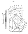
- FIG. 1 illustrates a constant velocity universal joint (Rzeppa type constant velocity universal joint: BJ).
- the constant velocity universal joint is constituted by an outer race 3 serving as an outer joint member having an inner spherical surface 1 in which curved track grooves 2 are formed in an axial direction, an inner race 6 serving as an inner joint member having an outer spherical surface 4 in which curved track grooves 5 are formed in the axial direction, multiple torque transmission balls 7 arranged in ball tracks formed by cooperation of the track grooves 2 of the outer race 3 and the track grooves 5 of the inner race 6 corresponding thereto, and a retainer (cage) 9 provided with pockets 8 for retaining the torque transmission balls 7.
- a retainer (cage) 9 provided with pockets 8 for retaining the torque transmission balls 7.
- the inner race 6 is subjected to spline fitting in which a shaft (not shown) is inserted into a center hole (inner hole) thereof, and the spline fitting enables torque transmission therebetween.
- a spline portion 12 is formed on an inner surface 11 of the inner joint member (inner race) 6.
- the outer race 3 is constituted by a mouth portion 3a in which the track grooves 2 are formed and a stem portion 3b protruding from a bottom wall of the mouth portion 3a.
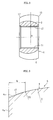
- a tapered relief portion 17 retracted with respect to the outer spherical surface 4 of curvature radius R.
- the outer spherical surface 4 and the tapered relief portion 17 are formed with curvature radius R1 smaller than the curvature radius R of the outer spherical surface 4 so as to be smoothly continuous with each other.
- the outer spherical surface 4 is retracted to a radially inner side with respect to the back end portion 4a (a range defined by an imaginary line illustrated in FIG. 3 ) in the case where the relief portion 17 is not provided.
- a range H of the relief portion 17 (range from back end surface 6a of inner race 6 to an intersection of tapered relief portion 17 and outer spherical surface 4) be set to be 3 mm or less.
- Curvature radius of an inner surface 9a of the cage 9 and the curvature radius R of the outer spherical surface 4 of the inner race 6 are set to be substantially equal to each other, and curvature radius of an outer surface 9b of the cage 9 and curvature radius of the inner spherical surface 1 of the outer race 3 are set to be substantially equal to each other.
- the relief portion 17 is provided at the back end portion of the outer spherical surface 4 of the inner race 6 serving as an inner joint member, whereby it is possible to eliminate biting of the back end portion of the inner race 6 into the cage inner surface 9a. With this, it is possible to achieve smooth rotation so as to reduce excessive load to the cage 9. As a result, the cage 9 can be strengthened.
- the range H of the relief portion 17 By setting the range H of the relief portion 17 to be 3 mm or less when measured from the back end surface of the inner race 6, it is possible to effectively secure the contact area between the inner race 6 and the cage 9. With this, surface pressure between the inner race 6 and the cage 9 can be reduced so as to suppress generation of heat, whereby life of the constant velocity universal joint can be increased.
- the relief portion 17 is excessively large, the contact area between the inner race 6 and the cage 9 are reduced. As a result, the surface pressure between the inner race 6 and the cage 9 becomes higher so that generation of heat is increased, which leads to a risk of a decrease in life of the constant velocity universal joint.
- the range H of the relief portion 17 be set to be 0.5 mm or more.
- the constant velocity universal joint in the constant velocity universal joint, five to eight torque transmission balls 7 can be used.
- the constant velocity universal joint by being provided with the eight torque transmission balls 7, the constant velocity universal joint can be further compactified and reduced in weight while strength, load capacity, and durability thereof are secured.
- the present invention is also applicable to a fixed type constant velocity universal joint (UJ) of undercut free type in which the track grooves on an opening side of the outer joint member have a straight shape parallel to the axial direction.
- UJ constant velocity universal joint
Landscapes
- Engineering & Computer Science (AREA)
- General Engineering & Computer Science (AREA)
- Mechanical Engineering (AREA)
- Rolling Contact Bearings (AREA)
- Pivots And Pivotal Connections (AREA)
- Power Steering Mechanism (AREA)
Abstract
Description
- The present invention relates to a constant velocity universal joint, and more specifically, to a fixed type constant velocity universal joint to be used in power transmission systems of automobiles and various kinds of industrial machines, which only allows an operating angle displacement between a shaft on the power-transmitting side and a shaft on the driven side.
- For example, a fixed type constant velocity universal joint (Rzeppa constant velocity universal joint: BJ) used for the connection between drive shafts or the like in automobiles includes: an outer joint member in which curved track grooves are axially formed on its inner surface with a spherical shape; an inner joint member in which curved track grooves are axially formed on its outer surface with a spherical shape; multiple torque transmission balls respectively arranged in ball tracks formed by cooperation of the track grooves of the inner joint member and the track grooves of the outer joint members corresponding thereto; and a retainer (cage) having pockets for respectively holding those torque transmission balls.
- Further, there may be cases where a wheel base is lengthened from the viewpoint of improving the safety of automobile in the event of a crash. In this case, however, in order to prevent a turning radius of the vehicle, there is a need to increase a steering angle for front wheels by providing the fixed type constant velocity universal joint with a higher operating angle. For filling the need for such a higher-angle, there is provided an undercut-free type fixed constant velocity universal joint (UJ) in which the track grooves on the opening side of the outer joint member have a straight shape parallel to the axial direction of the joint. In this kind of constant velocity universal joint, there is no under cut formed on either of the outer joint member or the inner joint member so that a higher operating angle can be attained.
- Examples of the fixed type constant velocity universal joint in recent years include one having a retainer (cage) increased in strength and durability (Patent Document 1), and one prevented from operational failures liable to occur when a high operating angle is formed and large torque is born (Patent Document 2).
- In the constant velocity universal joint disclosed in
Patent Document 1, a dimensional relation between curvature radius of corner radius portions and diameter of torque transmission balls are set in cage pockets. With this setting, surface areas of an inner surface and an outer surface of a retainer (cage) are increased. With this increase and an effect of a decrease in maximum main stress load in pole portions between pockets adjacent to each other in a circumferential direction, the cage can be increased in strength and durability. - Incidentally, in the fixed type constant velocity universal joint of those types, track grooves in the inner race are formed to be deeper at one end portions (inlet side) and shallower at the other end portions (back side). Therefore, there is a risk that, in the vicinity of the shallower end portion at which the torque transmission balls are positioned when a high operating angle is formed, contact ellipses of the torque transmission balls run onto shoulder portions of the track grooves so as to cause failures such as cracking or swelling of edge portions. Under the circumstance, in the fixed type constant velocity universal joint disclosed in
Patent Document 2, a relief portion is provided on an outer spherical surface on a side of the inner race (back side), on which the track grooves are shallower, while being retracted with respect to the outer spherical surface. With this, even when swelling and the like occur, the relief portion absorbs the swelling and the like so as to prevent operational failures from occurring. - [Patent Document 1]
JP 2002-13544 A - [Patent Document 2]
JP 11-190354 A - However, in
Patent Document 1, even though the dimensional relation between the curvature radius of the corner radius portions and the diameter of the torque transmission balls are set, there is a risk that the cage suffers breakage at an early stage when a high operating angle is formed and large load is applied. That is, when the constant velocity universal joint forms a high operating angle and is rotated while bearing large torque, a spherical force is generated between the inner race and the cage and between the cage and the outer race. By the spherical force, the inner race comes into contact with the inner surface of the cage with a high contact force. When a high operating angle is formed, the edge portions on the back side end surface of the inner race are rotated in a direction of biting into the cage inner surface. Therefore, smooth rotation cannot be achieved so that excessive load is applied to the cage. With this, there is a risk that the cage suffers breakage at an early stage when a high operating angle is formed and large load is applied. - Further, as described in
Patent Document 2, even when the relief portion is formed on the back side of the inner race, the edge portions are formed on the end surface of the back side of the inner race. Thus, in this case also, there is a risk that the edge portions bite into the cage inner surface when a high operating angle is formed. - In order to solve the above-mentioned problems, the present invention provides a constant velocity universal joint capable of being smoothly rotated even when a high operating angle is formed and large torque is born and of reducing excessive load applied to the cage so as to strengthen the cage.
- A constant velocity universal joint according to the present invention comprises: an outer joint member having an inner spherical surface in which multiple track grooves are formed; an inner joint member having an outer spherical surface in which multiple track grooves paired with the track grooves of the outer joint member are formed; multiple balls interposed between the track grooves of the outer joint member and the track grooves of the inner joint member so as to transmit torque; and a cage interposed between the inner spherical surface of the outer joint member and the outer spherical surface of the inner joint member so as to retain the balls. In the constant velocity universal joint, a tapered relief portion retracted with respect to the outer spherical surface is formed with low curvature at a back end portion of the outer spherical surface of the inner joint member so as to be smoothly continuous with the outer spherical surface.
- In the constant velocity universal joint of the present invention, the relief portion is formed at the back end portion of the outer spherical surface of the inner joint member. With this, it is possible to eliminate biting into the cage inner surface of the back end portion of the inner joint member.
- The relief portion is preferably provided within a range of 3 mm or less measured from a back end surface of the inner joint member. Further, the multiple balls may comprise five to eight balls.
- According to the constant velocity universal joint of the present invention, it is possible to eliminate biting into the cage inner surface of the back end portion of the inner joint member. With this, it is possible to achieve smooth rotation so as to reduce excessive load applied to the cage, to thereby strengthen the cage.
- By setting a range of the relief portion to be 3 mm or less when measured from the back end surface of the inner joint member, it is possible to effectively secure the contact area between the inner joint member and the cage. With this, surface pressure between the inner joint member and the cage can be reduced so as to suppress generation of heat, whereby life of the constant velocity universal joint can be increased. When the relief portion is excessively large, the contact area between the inner joint member and the cage are reduced. As a result, the surface pressure between the inner joint member and the cage becomes higher so that generation of heat is increased, which leads to a risk of a decrease in life of the constant velocity universal joint.
- Further, five to eight torque transmission balls can be used. In particular, by being provided with the eight torque transmission balls, the constant velocity universal joint can be further compactified and reduced in weight while strength, load capacity, and durability thereof are secured.
-
-
FIG. 1 is a sectional view of a constant velocity universal joint according to an embodiment of the present invention. -
FIG. 2 is a sectional view of an inner race of the constant velocity universal joint. -
FIG. 3 is a sectional view of a main portion of the inner race of the constant velocity universal joint. -
- 1
- inner spherical surface
- 2
- track groove
- 4
- outer spherical surface
- 5
- track groove
- 6
- inner race
- 7
- torque transmission ball
- 9
- retainer (cage)
- 15
- end portion
- 17
- relief portion
- In the following, an embodiment of the present invention is described with reference to
FIGS. 1 to 3 . -
FIG. 1 illustrates a constant velocity universal joint (Rzeppa type constant velocity universal joint: BJ). The constant velocity universal joint is constituted by anouter race 3 serving as an outer joint member having an innerspherical surface 1 in which curvedtrack grooves 2 are formed in an axial direction, aninner race 6 serving as an inner joint member having an outerspherical surface 4 in which curvedtrack grooves 5 are formed in the axial direction, multipletorque transmission balls 7 arranged in ball tracks formed by cooperation of thetrack grooves 2 of theouter race 3 and thetrack grooves 5 of theinner race 6 corresponding thereto, and a retainer (cage) 9 provided withpockets 8 for retaining thetorque transmission balls 7. - The
inner race 6 is subjected to spline fitting in which a shaft (not shown) is inserted into a center hole (inner hole) thereof, and the spline fitting enables torque transmission therebetween. Thus, aspline portion 12 is formed on aninner surface 11 of the inner joint member (inner race) 6. Further, theouter race 3 is constituted by amouth portion 3a in which thetrack grooves 2 are formed and astem portion 3b protruding from a bottom wall of themouth portion 3a. - As illustrated in
FIG. 2 , at aback end portion 4a of the outerspherical surface 4 of theinner race 6, there is formed atapered relief portion 17 retracted with respect to the outerspherical surface 4 of curvature radius R. The outerspherical surface 4 and the taperedrelief portion 17 are formed with curvature radius R1 smaller than the curvature radius R of the outerspherical surface 4 so as to be smoothly continuous with each other. Thus, the outerspherical surface 4 is retracted to a radially inner side with respect to theback end portion 4a (a range defined by an imaginary line illustrated inFIG. 3 ) in the case where therelief portion 17 is not provided. Further, it is preferable that a range H of the relief portion 17 (range fromback end surface 6a ofinner race 6 to an intersection of taperedrelief portion 17 and outer spherical surface 4) be set to be 3 mm or less. - Curvature radius of an
inner surface 9a of thecage 9 and the curvature radius R of the outerspherical surface 4 of theinner race 6 are set to be substantially equal to each other, and curvature radius of anouter surface 9b of thecage 9 and curvature radius of the innerspherical surface 1 of theouter race 3 are set to be substantially equal to each other. Thus, when an operating angle is formed, theouter surface 9b of thecage 9 slides on the innerspherical surface 1 of theouter race 3, and the outerspherical surface 4 of theinner race 6 slides on theinner surface 9a of thecage 9. - In the present invention, the
relief portion 17 is provided at the back end portion of the outerspherical surface 4 of theinner race 6 serving as an inner joint member, whereby it is possible to eliminate biting of the back end portion of theinner race 6 into the cageinner surface 9a. With this, it is possible to achieve smooth rotation so as to reduce excessive load to thecage 9. As a result, thecage 9 can be strengthened. - By setting the range H of the
relief portion 17 to be 3 mm or less when measured from the back end surface of theinner race 6, it is possible to effectively secure the contact area between theinner race 6 and thecage 9. With this, surface pressure between theinner race 6 and thecage 9 can be reduced so as to suppress generation of heat, whereby life of the constant velocity universal joint can be increased. When therelief portion 17 is excessively large, the contact area between theinner race 6 and thecage 9 are reduced. As a result, the surface pressure between theinner race 6 and thecage 9 becomes higher so that generation of heat is increased, which leads to a risk of a decrease in life of the constant velocity universal joint. Note that, when therelief portion 17 is excessively small, therelief portion 17 cannot exert the function thereas. Thus, it is preferable that the range H of therelief portion 17 be set to be 0.5 mm or more. - Incidentally, in the constant velocity universal joint, five to eight
torque transmission balls 7 can be used. In particular, by being provided with the eighttorque transmission balls 7, the constant velocity universal joint can be further compactified and reduced in weight while strength, load capacity, and durability thereof are secured. - The present invention is also applicable to a fixed type constant velocity universal joint (UJ) of undercut free type in which the track grooves on an opening side of the outer joint member have a straight shape parallel to the axial direction.
Claims (3)
- A constant velocity universal joint, comprising:an outer joint member having an inner spherical surface in which multiple track grooves are formed;an inner joint member having an outer spherical surface in which multiple track grooves paired with the track grooves of the outer joint member are formed;multiple balls interposed between the track grooves of the outer joint member and the track grooves of the inner joint member so as to transmit torque; anda cage interposed between the inner spherical surface of the outer joint member and the outer spherical surface of the inner joint member so as to retain the balls,wherein a tapered relief portion retracted with respect to the outer spherical surface is formed with low curvature at a back end portion of the outer spherical surface of the inner joint member so as to be smoothly continuous with the outer spherical surface.
- A constant velocity universal joint according to claim 1, wherein the relief portion is provided within a range of 3 mm or less measured from a back end surface of the inner joint member.
- A constant velocity universal joint according to claim 1 or 2, wherein the multiple balls comprise five to eight balls.
Applications Claiming Priority (2)
| Application Number | Priority Date | Filing Date | Title |
|---|---|---|---|
| JP2007073461A JP5143453B2 (en) | 2007-03-20 | 2007-03-20 | Constant velocity universal joint |
| PCT/JP2008/053015 WO2008114574A1 (en) | 2007-03-20 | 2008-02-22 | Constant velocity universal joint |
Publications (3)
| Publication Number | Publication Date |
|---|---|
| EP2133582A1 true EP2133582A1 (en) | 2009-12-16 |
| EP2133582A4 EP2133582A4 (en) | 2017-04-26 |
| EP2133582B1 EP2133582B1 (en) | 2018-09-26 |
Family
ID=39765684
Family Applications (1)
| Application Number | Title | Priority Date | Filing Date |
|---|---|---|---|
| EP08711789.1A Active EP2133582B1 (en) | 2007-03-20 | 2008-02-22 | Constant velocity universal joint |
Country Status (5)
| Country | Link |
|---|---|
| US (1) | US8182352B2 (en) |
| EP (1) | EP2133582B1 (en) |
| JP (1) | JP5143453B2 (en) |
| CN (1) | CN101688563A (en) |
| WO (1) | WO2008114574A1 (en) |
Cited By (1)
| Publication number | Priority date | Publication date | Assignee | Title |
|---|---|---|---|---|
| US8499457B2 (en) | 2008-11-06 | 2013-08-06 | Ntn Corporation | Fixed constant velocity universal joint, method of manufacturing fixed constant velocity universal joint, and bearing device adapted for use in driving wheel and using fixed constant velocity universal joint |
Families Citing this family (1)
| Publication number | Priority date | Publication date | Assignee | Title |
|---|---|---|---|---|
| WO2022176105A1 (en) * | 2021-02-18 | 2022-08-25 | 株式会社ジェイテクト | Constant velocity universal joint and manufacturing method of constant velocity universal joint |
Family Cites Families (12)
| Publication number | Priority date | Publication date | Assignee | Title |
|---|---|---|---|---|
| JPS6039897B2 (en) * | 1978-12-04 | 1985-09-07 | エヌ・テ−・エヌ東洋ベアリング株式会社 | Constant velocity joint |
| DE3233753A1 (en) * | 1982-09-11 | 1984-03-15 | Sobhy Labib Dipl.-Ing. 5210 Troisdorf Girguis | CV DRIVE JOINT |
| JPS60249728A (en) * | 1984-05-25 | 1985-12-10 | Nippon Seiko Kk | Equi-speed joint |
| JPH0799176B2 (en) * | 1989-07-17 | 1995-10-25 | エヌティエヌ株式会社 | Constant velocity universal joint |
| JP2750162B2 (en) * | 1989-07-28 | 1998-05-13 | エヌティエヌ株式会社 | Constant velocity joint |
| JP3570811B2 (en) * | 1996-02-14 | 2004-09-29 | Ntn株式会社 | Automobile power transmission device and its constant velocity universal joint |
| JPH11190354A (en) | 1997-12-25 | 1999-07-13 | Ntn Corp | Constant speed universal joint |
| JP2002013544A (en) | 2000-06-27 | 2002-01-18 | Ntn Corp | Constant velocity universal joint |
| WO2005033538A1 (en) * | 2003-10-01 | 2005-04-14 | Ntn Corporation | Fixed type constant velocity universal joint |
| JP4554181B2 (en) | 2003-10-01 | 2010-09-29 | Ntn株式会社 | Fixed type constant velocity universal joint |
| JP4712304B2 (en) * | 2004-02-06 | 2011-06-29 | Ntn株式会社 | Fixed constant velocity universal joint |
| JP4959177B2 (en) * | 2005-11-18 | 2012-06-20 | Ntn株式会社 | Fixed constant velocity universal joint |
-
2007
- 2007-03-20 JP JP2007073461A patent/JP5143453B2/en active Active
-
2008
- 2008-02-22 CN CN200880008546A patent/CN101688563A/en active Pending
- 2008-02-22 WO PCT/JP2008/053015 patent/WO2008114574A1/en not_active Ceased
- 2008-02-22 EP EP08711789.1A patent/EP2133582B1/en active Active
- 2008-02-22 US US12/529,743 patent/US8182352B2/en active Active
Cited By (1)
| Publication number | Priority date | Publication date | Assignee | Title |
|---|---|---|---|---|
| US8499457B2 (en) | 2008-11-06 | 2013-08-06 | Ntn Corporation | Fixed constant velocity universal joint, method of manufacturing fixed constant velocity universal joint, and bearing device adapted for use in driving wheel and using fixed constant velocity universal joint |
Also Published As
| Publication number | Publication date |
|---|---|
| EP2133582B1 (en) | 2018-09-26 |
| US20100113168A1 (en) | 2010-05-06 |
| JP2008232293A (en) | 2008-10-02 |
| EP2133582A4 (en) | 2017-04-26 |
| CN101688563A (en) | 2010-03-31 |
| WO2008114574A1 (en) | 2008-09-25 |
| US8182352B2 (en) | 2012-05-22 |
| JP5143453B2 (en) | 2013-02-13 |
Similar Documents
| Publication | Publication Date | Title |
|---|---|---|
| CN102209857B (en) | Fixed type constant velocity universal joint, manufacturing method thereof, and bearing unit for drive wheel using the fixed type constant velocity universal joint | |
| CN102066794B (en) | Fixed-type constant-velocity universal joint | |
| US20140038733A1 (en) | Fixed type constant velocity universal joint | |
| US8388456B2 (en) | Fixed-type, constant-velocity universal joint | |
| JP4041657B2 (en) | Constant velocity universal joint | |
| EP1705395B1 (en) | Fixed-type constant-velocity universal joint | |
| US8342971B2 (en) | Fixed type constant velocity universal joint | |
| US20120010005A1 (en) | Cross groove-type constant-velocity universal joint | |
| EP2133582B1 (en) | Constant velocity universal joint | |
| JP2011231792A (en) | Sliding constant velocity universal joint, and ironing process method of outer joint member thereof | |
| EP2202422B1 (en) | Constant velocity universal joint | |
| CN101493120A (en) | Constant velocity joint | |
| US7651400B2 (en) | Constant velocity universal joint and inner member thereof | |
| JP2008151182A (en) | Constant velocity universal joint | |
| EP2594820A1 (en) | Constant-velocity ball joint | |
| CN102405357B (en) | Tripod constant-velocity universal joint and method for producing the same | |
| CN101313159B (en) | Fixed constant velocity universal joint | |
| JP4901530B2 (en) | Constant velocity universal joint | |
| JP2000104749A (en) | Stationary constant-velocity joint | |
| JP2012021546A (en) | Fixed type constant velocity universal joint | |
| CN118257792A (en) | Power transmission shaft, drive shaft, and outer coupling member | |
| JP2007271040A (en) | Fixed type constant velocity universal joint |
Legal Events
| Date | Code | Title | Description |
|---|---|---|---|
| PUAI | Public reference made under article 153(3) epc to a published international application that has entered the european phase |
Free format text: ORIGINAL CODE: 0009012 |
|
| 17P | Request for examination filed |
Effective date: 20091005 |
|
| AK | Designated contracting states |
Kind code of ref document: A1 Designated state(s): AT BE BG CH CY CZ DE DK EE ES FI FR GB GR HR HU IE IS IT LI LT LU LV MC MT NL NO PL PT RO SE SI SK TR |
|
| DAX | Request for extension of the european patent (deleted) | ||
| RA4 | Supplementary search report drawn up and despatched (corrected) |
Effective date: 20170329 |
|
| RIC1 | Information provided on ipc code assigned before grant |
Ipc: F16D 3/224 20110101AFI20170323BHEP Ipc: F16D 3/223 20110101ALI20170323BHEP Ipc: F16D 3/20 20060101ALI20170323BHEP |
|
| GRAP | Despatch of communication of intention to grant a patent |
Free format text: ORIGINAL CODE: EPIDOSNIGR1 |
|
| STAA | Information on the status of an ep patent application or granted ep patent |
Free format text: STATUS: GRANT OF PATENT IS INTENDED |
|
| INTG | Intention to grant announced |
Effective date: 20180531 |
|
| GRAS | Grant fee paid |
Free format text: ORIGINAL CODE: EPIDOSNIGR3 |
|
| RIN1 | Information on inventor provided before grant (corrected) |
Inventor name: KOBAYASHI, MASAZUMI |
|
| GRAA | (expected) grant |
Free format text: ORIGINAL CODE: 0009210 |
|
| STAA | Information on the status of an ep patent application or granted ep patent |
Free format text: STATUS: THE PATENT HAS BEEN GRANTED |
|
| AK | Designated contracting states |
Kind code of ref document: B1 Designated state(s): AT BE BG CH CY CZ DE DK EE ES FI FR GB GR HR HU IE IS IT LI LT LU LV MC MT NL NO PL PT RO SE SI SK TR |
|
| REG | Reference to a national code |
Ref country code: GB Ref legal event code: FG4D |
|
| REG | Reference to a national code |
Ref country code: CH Ref legal event code: EP |
|
| REG | Reference to a national code |
Ref country code: AT Ref legal event code: REF Ref document number: 1046379 Country of ref document: AT Kind code of ref document: T Effective date: 20181015 |
|
| REG | Reference to a national code |
Ref country code: IE Ref legal event code: FG4D |
|
| REG | Reference to a national code |
Ref country code: DE Ref legal event code: R096 Ref document number: 602008057140 Country of ref document: DE |
|
| REG | Reference to a national code |
Ref country code: NL Ref legal event code: MP Effective date: 20180926 |
|
| PG25 | Lapsed in a contracting state [announced via postgrant information from national office to epo] |
Ref country code: FI Free format text: LAPSE BECAUSE OF FAILURE TO SUBMIT A TRANSLATION OF THE DESCRIPTION OR TO PAY THE FEE WITHIN THE PRESCRIBED TIME-LIMIT Effective date: 20180926 Ref country code: SE Free format text: LAPSE BECAUSE OF FAILURE TO SUBMIT A TRANSLATION OF THE DESCRIPTION OR TO PAY THE FEE WITHIN THE PRESCRIBED TIME-LIMIT Effective date: 20180926 Ref country code: GR Free format text: LAPSE BECAUSE OF FAILURE TO SUBMIT A TRANSLATION OF THE DESCRIPTION OR TO PAY THE FEE WITHIN THE PRESCRIBED TIME-LIMIT Effective date: 20181227 Ref country code: NO Free format text: LAPSE BECAUSE OF FAILURE TO SUBMIT A TRANSLATION OF THE DESCRIPTION OR TO PAY THE FEE WITHIN THE PRESCRIBED TIME-LIMIT Effective date: 20181226 Ref country code: LT Free format text: LAPSE BECAUSE OF FAILURE TO SUBMIT A TRANSLATION OF THE DESCRIPTION OR TO PAY THE FEE WITHIN THE PRESCRIBED TIME-LIMIT Effective date: 20180926 Ref country code: BG Free format text: LAPSE BECAUSE OF FAILURE TO SUBMIT A TRANSLATION OF THE DESCRIPTION OR TO PAY THE FEE WITHIN THE PRESCRIBED TIME-LIMIT Effective date: 20181226 |
|
| REG | Reference to a national code |
Ref country code: LT Ref legal event code: MG4D |
|
| PG25 | Lapsed in a contracting state [announced via postgrant information from national office to epo] |
Ref country code: LV Free format text: LAPSE BECAUSE OF FAILURE TO SUBMIT A TRANSLATION OF THE DESCRIPTION OR TO PAY THE FEE WITHIN THE PRESCRIBED TIME-LIMIT Effective date: 20180926 Ref country code: HR Free format text: LAPSE BECAUSE OF FAILURE TO SUBMIT A TRANSLATION OF THE DESCRIPTION OR TO PAY THE FEE WITHIN THE PRESCRIBED TIME-LIMIT Effective date: 20180926 |
|
| REG | Reference to a national code |
Ref country code: AT Ref legal event code: MK05 Ref document number: 1046379 Country of ref document: AT Kind code of ref document: T Effective date: 20180926 |
|
| PG25 | Lapsed in a contracting state [announced via postgrant information from national office to epo] |
Ref country code: IS Free format text: LAPSE BECAUSE OF FAILURE TO SUBMIT A TRANSLATION OF THE DESCRIPTION OR TO PAY THE FEE WITHIN THE PRESCRIBED TIME-LIMIT Effective date: 20190126 Ref country code: RO Free format text: LAPSE BECAUSE OF FAILURE TO SUBMIT A TRANSLATION OF THE DESCRIPTION OR TO PAY THE FEE WITHIN THE PRESCRIBED TIME-LIMIT Effective date: 20180926 Ref country code: NL Free format text: LAPSE BECAUSE OF FAILURE TO SUBMIT A TRANSLATION OF THE DESCRIPTION OR TO PAY THE FEE WITHIN THE PRESCRIBED TIME-LIMIT Effective date: 20180926 Ref country code: ES Free format text: LAPSE BECAUSE OF FAILURE TO SUBMIT A TRANSLATION OF THE DESCRIPTION OR TO PAY THE FEE WITHIN THE PRESCRIBED TIME-LIMIT Effective date: 20180926 Ref country code: CZ Free format text: LAPSE BECAUSE OF FAILURE TO SUBMIT A TRANSLATION OF THE DESCRIPTION OR TO PAY THE FEE WITHIN THE PRESCRIBED TIME-LIMIT Effective date: 20180926 Ref country code: PL Free format text: LAPSE BECAUSE OF FAILURE TO SUBMIT A TRANSLATION OF THE DESCRIPTION OR TO PAY THE FEE WITHIN THE PRESCRIBED TIME-LIMIT Effective date: 20180926 Ref country code: AT Free format text: LAPSE BECAUSE OF FAILURE TO SUBMIT A TRANSLATION OF THE DESCRIPTION OR TO PAY THE FEE WITHIN THE PRESCRIBED TIME-LIMIT Effective date: 20180926 Ref country code: EE Free format text: LAPSE BECAUSE OF FAILURE TO SUBMIT A TRANSLATION OF THE DESCRIPTION OR TO PAY THE FEE WITHIN THE PRESCRIBED TIME-LIMIT Effective date: 20180926 Ref country code: IT Free format text: LAPSE BECAUSE OF FAILURE TO SUBMIT A TRANSLATION OF THE DESCRIPTION OR TO PAY THE FEE WITHIN THE PRESCRIBED TIME-LIMIT Effective date: 20180926 |
|
| PG25 | Lapsed in a contracting state [announced via postgrant information from national office to epo] |
Ref country code: SK Free format text: LAPSE BECAUSE OF FAILURE TO SUBMIT A TRANSLATION OF THE DESCRIPTION OR TO PAY THE FEE WITHIN THE PRESCRIBED TIME-LIMIT Effective date: 20180926 Ref country code: PT Free format text: LAPSE BECAUSE OF FAILURE TO SUBMIT A TRANSLATION OF THE DESCRIPTION OR TO PAY THE FEE WITHIN THE PRESCRIBED TIME-LIMIT Effective date: 20190126 |
|
| REG | Reference to a national code |
Ref country code: DE Ref legal event code: R097 Ref document number: 602008057140 Country of ref document: DE |
|
| PG25 | Lapsed in a contracting state [announced via postgrant information from national office to epo] |
Ref country code: DK Free format text: LAPSE BECAUSE OF FAILURE TO SUBMIT A TRANSLATION OF THE DESCRIPTION OR TO PAY THE FEE WITHIN THE PRESCRIBED TIME-LIMIT Effective date: 20180926 |
|
| PLBE | No opposition filed within time limit |
Free format text: ORIGINAL CODE: 0009261 |
|
| STAA | Information on the status of an ep patent application or granted ep patent |
Free format text: STATUS: NO OPPOSITION FILED WITHIN TIME LIMIT |
|
| 26N | No opposition filed |
Effective date: 20190627 |
|
| REG | Reference to a national code |
Ref country code: CH Ref legal event code: PL |
|
| GBPC | Gb: european patent ceased through non-payment of renewal fee |
Effective date: 20190222 |
|
| PG25 | Lapsed in a contracting state [announced via postgrant information from national office to epo] |
Ref country code: SI Free format text: LAPSE BECAUSE OF FAILURE TO SUBMIT A TRANSLATION OF THE DESCRIPTION OR TO PAY THE FEE WITHIN THE PRESCRIBED TIME-LIMIT Effective date: 20180926 Ref country code: LU Free format text: LAPSE BECAUSE OF NON-PAYMENT OF DUE FEES Effective date: 20190222 Ref country code: MC Free format text: LAPSE BECAUSE OF FAILURE TO SUBMIT A TRANSLATION OF THE DESCRIPTION OR TO PAY THE FEE WITHIN THE PRESCRIBED TIME-LIMIT Effective date: 20180926 |
|
| REG | Reference to a national code |
Ref country code: BE Ref legal event code: MM Effective date: 20190228 |
|
| REG | Reference to a national code |
Ref country code: IE Ref legal event code: MM4A |
|
| PG25 | Lapsed in a contracting state [announced via postgrant information from national office to epo] |
Ref country code: LI Free format text: LAPSE BECAUSE OF NON-PAYMENT OF DUE FEES Effective date: 20190228 Ref country code: CH Free format text: LAPSE BECAUSE OF NON-PAYMENT OF DUE FEES Effective date: 20190228 |
|
| PG25 | Lapsed in a contracting state [announced via postgrant information from national office to epo] |
Ref country code: IE Free format text: LAPSE BECAUSE OF NON-PAYMENT OF DUE FEES Effective date: 20190222 Ref country code: GB Free format text: LAPSE BECAUSE OF NON-PAYMENT OF DUE FEES Effective date: 20190222 |
|
| PG25 | Lapsed in a contracting state [announced via postgrant information from national office to epo] |
Ref country code: BE Free format text: LAPSE BECAUSE OF NON-PAYMENT OF DUE FEES Effective date: 20190228 |
|
| PG25 | Lapsed in a contracting state [announced via postgrant information from national office to epo] |
Ref country code: TR Free format text: LAPSE BECAUSE OF FAILURE TO SUBMIT A TRANSLATION OF THE DESCRIPTION OR TO PAY THE FEE WITHIN THE PRESCRIBED TIME-LIMIT Effective date: 20180926 |
|
| PG25 | Lapsed in a contracting state [announced via postgrant information from national office to epo] |
Ref country code: MT Free format text: LAPSE BECAUSE OF NON-PAYMENT OF DUE FEES Effective date: 20190222 |
|
| PG25 | Lapsed in a contracting state [announced via postgrant information from national office to epo] |
Ref country code: CY Free format text: LAPSE BECAUSE OF FAILURE TO SUBMIT A TRANSLATION OF THE DESCRIPTION OR TO PAY THE FEE WITHIN THE PRESCRIBED TIME-LIMIT Effective date: 20180926 |
|
| PG25 | Lapsed in a contracting state [announced via postgrant information from national office to epo] |
Ref country code: HU Free format text: LAPSE BECAUSE OF FAILURE TO SUBMIT A TRANSLATION OF THE DESCRIPTION OR TO PAY THE FEE WITHIN THE PRESCRIBED TIME-LIMIT; INVALID AB INITIO Effective date: 20080222 |
|
| PGFP | Annual fee paid to national office [announced via postgrant information from national office to epo] |
Ref country code: FR Payment date: 20251231 Year of fee payment: 19 |
|
| PGFP | Annual fee paid to national office [announced via postgrant information from national office to epo] |
Ref country code: DE Payment date: 20251230 Year of fee payment: 19 |