EP2133134A1 - Apparatus and method for treating discharge gas - Google Patents
Apparatus and method for treating discharge gas Download PDFInfo
- Publication number
- EP2133134A1 EP2133134A1 EP07790937A EP07790937A EP2133134A1 EP 2133134 A1 EP2133134 A1 EP 2133134A1 EP 07790937 A EP07790937 A EP 07790937A EP 07790937 A EP07790937 A EP 07790937A EP 2133134 A1 EP2133134 A1 EP 2133134A1
- Authority
- EP
- European Patent Office
- Prior art keywords
- air pollution
- pollution control
- control apparatus
- ammonium
- chloride
- Prior art date
- Legal status (The legal status is an assumption and is not a legal conclusion. Google has not performed a legal analysis and makes no representation as to the accuracy of the status listed.)
- Granted
Links
Images



Classifications
-
- B—PERFORMING OPERATIONS; TRANSPORTING
- B01—PHYSICAL OR CHEMICAL PROCESSES OR APPARATUS IN GENERAL
- B01D—SEPARATION
- B01D53/00—Separation of gases or vapours; Recovering vapours of volatile solvents from gases; Chemical or biological purification of waste gases, e.g. engine exhaust gases, smoke, fumes, flue gases, aerosols
- B01D53/34—Chemical or biological purification of waste gases
- B01D53/46—Removing components of defined structure
- B01D53/64—Heavy metals or compounds thereof, e.g. mercury
-
- B—PERFORMING OPERATIONS; TRANSPORTING
- B01—PHYSICAL OR CHEMICAL PROCESSES OR APPARATUS IN GENERAL
- B01D—SEPARATION
- B01D53/00—Separation of gases or vapours; Recovering vapours of volatile solvents from gases; Chemical or biological purification of waste gases, e.g. engine exhaust gases, smoke, fumes, flue gases, aerosols
- B01D53/34—Chemical or biological purification of waste gases
- B01D53/74—General processes for purification of waste gases; Apparatus or devices specially adapted therefor
- B01D53/86—Catalytic processes
- B01D53/8621—Removing nitrogen compounds
- B01D53/8625—Nitrogen oxides
-
- B—PERFORMING OPERATIONS; TRANSPORTING
- B01—PHYSICAL OR CHEMICAL PROCESSES OR APPARATUS IN GENERAL
- B01D—SEPARATION
- B01D53/00—Separation of gases or vapours; Recovering vapours of volatile solvents from gases; Chemical or biological purification of waste gases, e.g. engine exhaust gases, smoke, fumes, flue gases, aerosols
- B01D53/34—Chemical or biological purification of waste gases
- B01D53/74—General processes for purification of waste gases; Apparatus or devices specially adapted therefor
- B01D53/86—Catalytic processes
- B01D53/8665—Removing heavy metals or compounds thereof, e.g. mercury
-
- F—MECHANICAL ENGINEERING; LIGHTING; HEATING; WEAPONS; BLASTING
- F23—COMBUSTION APPARATUS; COMBUSTION PROCESSES
- F23J—REMOVAL OR TREATMENT OF COMBUSTION PRODUCTS OR COMBUSTION RESIDUES; FLUES
- F23J15/00—Arrangements of devices for treating smoke or fumes
- F23J15/003—Arrangements of devices for treating smoke or fumes for supplying chemicals to fumes, e.g. using injection devices
-
- F—MECHANICAL ENGINEERING; LIGHTING; HEATING; WEAPONS; BLASTING
- F23—COMBUSTION APPARATUS; COMBUSTION PROCESSES
- F23J—REMOVAL OR TREATMENT OF COMBUSTION PRODUCTS OR COMBUSTION RESIDUES; FLUES
- F23J15/00—Arrangements of devices for treating smoke or fumes
- F23J15/02—Arrangements of devices for treating smoke or fumes of purifiers, e.g. for removing noxious material
-
- F—MECHANICAL ENGINEERING; LIGHTING; HEATING; WEAPONS; BLASTING
- F23—COMBUSTION APPARATUS; COMBUSTION PROCESSES
- F23L—SUPPLYING AIR OR NON-COMBUSTIBLE LIQUIDS OR GASES TO COMBUSTION APPARATUS IN GENERAL ; VALVES OR DAMPERS SPECIALLY ADAPTED FOR CONTROLLING AIR SUPPLY OR DRAUGHT IN COMBUSTION APPARATUS; INDUCING DRAUGHT IN COMBUSTION APPARATUS; TOPS FOR CHIMNEYS OR VENTILATING SHAFTS; TERMINALS FOR FLUES
- F23L15/00—Heating of air supplied for combustion
- F23L15/04—Arrangements of recuperators
-
- B—PERFORMING OPERATIONS; TRANSPORTING
- B01—PHYSICAL OR CHEMICAL PROCESSES OR APPARATUS IN GENERAL
- B01D—SEPARATION
- B01D2251/00—Reactants
- B01D2251/20—Reductants
- B01D2251/206—Ammonium compounds
-
- B—PERFORMING OPERATIONS; TRANSPORTING
- B01—PHYSICAL OR CHEMICAL PROCESSES OR APPARATUS IN GENERAL
- B01D—SEPARATION
- B01D2251/00—Reactants
- B01D2251/20—Reductants
- B01D2251/206—Ammonium compounds
- B01D2251/2062—Ammonia
-
- B—PERFORMING OPERATIONS; TRANSPORTING
- B01—PHYSICAL OR CHEMICAL PROCESSES OR APPARATUS IN GENERAL
- B01D—SEPARATION
- B01D2251/00—Reactants
- B01D2251/50—Inorganic acids
- B01D2251/502—Hydrochloric acid
-
- B—PERFORMING OPERATIONS; TRANSPORTING
- B01—PHYSICAL OR CHEMICAL PROCESSES OR APPARATUS IN GENERAL
- B01D—SEPARATION
- B01D2257/00—Components to be removed
- B01D2257/60—Heavy metals or heavy metal compounds
- B01D2257/602—Mercury or mercury compounds
-
- F—MECHANICAL ENGINEERING; LIGHTING; HEATING; WEAPONS; BLASTING
- F23—COMBUSTION APPARATUS; COMBUSTION PROCESSES
- F23J—REMOVAL OR TREATMENT OF COMBUSTION PRODUCTS OR COMBUSTION RESIDUES; FLUES
- F23J2215/00—Preventing emissions
- F23J2215/20—Sulfur; Compounds thereof
-
- F—MECHANICAL ENGINEERING; LIGHTING; HEATING; WEAPONS; BLASTING
- F23—COMBUSTION APPARATUS; COMBUSTION PROCESSES
- F23J—REMOVAL OR TREATMENT OF COMBUSTION PRODUCTS OR COMBUSTION RESIDUES; FLUES
- F23J2215/00—Preventing emissions
- F23J2215/60—Heavy metals; Compounds thereof
-
- F—MECHANICAL ENGINEERING; LIGHTING; HEATING; WEAPONS; BLASTING
- F23—COMBUSTION APPARATUS; COMBUSTION PROCESSES
- F23J—REMOVAL OR TREATMENT OF COMBUSTION PRODUCTS OR COMBUSTION RESIDUES; FLUES
- F23J2219/00—Treatment devices
- F23J2219/10—Catalytic reduction devices
-
- F—MECHANICAL ENGINEERING; LIGHTING; HEATING; WEAPONS; BLASTING
- F23—COMBUSTION APPARATUS; COMBUSTION PROCESSES
- F23J—REMOVAL OR TREATMENT OF COMBUSTION PRODUCTS OR COMBUSTION RESIDUES; FLUES
- F23J2219/00—Treatment devices
- F23J2219/60—Sorption with dry devices, e.g. beds
-
- Y—GENERAL TAGGING OF NEW TECHNOLOGICAL DEVELOPMENTS; GENERAL TAGGING OF CROSS-SECTIONAL TECHNOLOGIES SPANNING OVER SEVERAL SECTIONS OF THE IPC; TECHNICAL SUBJECTS COVERED BY FORMER USPC CROSS-REFERENCE ART COLLECTIONS [XRACs] AND DIGESTS
- Y02—TECHNOLOGIES OR APPLICATIONS FOR MITIGATION OR ADAPTATION AGAINST CLIMATE CHANGE
- Y02A—TECHNOLOGIES FOR ADAPTATION TO CLIMATE CHANGE
- Y02A50/00—TECHNOLOGIES FOR ADAPTATION TO CLIMATE CHANGE in human health protection, e.g. against extreme weather
- Y02A50/20—Air quality improvement or preservation, e.g. vehicle emission control or emission reduction by using catalytic converters
-
- Y—GENERAL TAGGING OF NEW TECHNOLOGICAL DEVELOPMENTS; GENERAL TAGGING OF CROSS-SECTIONAL TECHNOLOGIES SPANNING OVER SEVERAL SECTIONS OF THE IPC; TECHNICAL SUBJECTS COVERED BY FORMER USPC CROSS-REFERENCE ART COLLECTIONS [XRACs] AND DIGESTS
- Y02—TECHNOLOGIES OR APPLICATIONS FOR MITIGATION OR ADAPTATION AGAINST CLIMATE CHANGE
- Y02E—REDUCTION OF GREENHOUSE GAS [GHG] EMISSIONS, RELATED TO ENERGY GENERATION, TRANSMISSION OR DISTRIBUTION
- Y02E20/00—Combustion technologies with mitigation potential
- Y02E20/34—Indirect CO2mitigation, i.e. by acting on non CO2directly related matters of the process, e.g. pre-heating or heat recovery
Definitions
- the present invention relates to an air pollution control apparatus and an air pollution control method.
- Fig. 5 is a schematic diagram of an air pollution control apparatus of a coal combustion boiler.
- combustion gas 11 generates steam in a generating tube within a furnace 12 of a coal combustion boiler 10 (the generated steam is separated into gas and liquid by a steam drum 13, the steam is guided into a super heater 14 and becomes overheated steam, the steam is used for driving a steam turbine, and then condensed water is circulated into a water tube in the furnace 12 and is again evaporated).
- the steam is overheated by the super heater 14 to heat water to be supplied to the coal combustion boiler 10 in an economizer 15, and then the steam is discharged from an exit of the economizer 15 as flue gas 16.
- the flue gas 16 from the economizer 15 is supplied to a denitrator 17, heats air 19 by heat exchange in an air heater 18, is supplied to a dust collector 20, is further supplied to a desulfurizer 21, and then is discharged to atmosphere as purge gas 22.
- the denitrator 17 As the denitrator 17, one is proposed which sprays ammonium (NH 3 ) to the flue gas 16 from the coal combustion boiler 10 upstream of the denitrator (catalyst unit), thereby reducing and denitrating the flue gas 16.
- a system is proposed that sprays a chlorinating agent such as HCl upstream of the denitrator 17, oxidizes (chlorinates) the mercury on a catalyst, and reduces the mercury by a wet desulfurizer installed downstream (Patent Document 1).
- Patent Document 1 Japanese Patent Application Laid-open No. H10-230137
- an object of the present invention to provide an air pollution control apparatus and an air pollution control method capable of easy storage, in which the efficiency in removing nitrogen oxides and mercury is not deteriorated, as the measures for flue gas.
- the supplied powdery ammonium chloride is sublimated by combustion gas, and hydrogen chloride and ammonium are supplied into the flue.
- a particle diameter of the powdery ammonium chloride is 0.25 millimeter or less.
- any one of an HCl supply unit and an NH 3 supply unit, or both of them are provided downstream of the economizer.
- the ammonium chloride supply unit includes a crushing unit that crushes solid ammonium chloride.
- the air pollution control apparatus further includes a vaporizer that heats and vaporizes the ammonium chloride supplied from the ammonium-chloride supply unit.
- the air pollution control apparatus further includes a vaporizer that heats and vaporizes the ammonium-chloride supplied from the ammonium-chloride supply unit, and a particle diameter of the powdery ammonium chloride is 0.25 millimeter or less.
- an air pollution control method for reducing nitrogen oxides and oxidizing mercury in flue gas from a boiler by using an ammonia denitrating catalyst includes: supplying powdery ammonium chloride to a location near an entrance of an economizer provided in a flue of a boiler or to an economizer bypassing unit, or both of them; sublimating the ammonium chloride in an atmosphere at a temperature of combustion gas at a supply location; and supplying hydrogen chloride and ammonium into the flue.
- HCl and NH 3 are vaporized by the high-temperature (550 to 650°C) combustion gas by adding the powdery ammonium chloride (NH 4 Cl).
- NH 4 Cl powdery ammonium chloride
- FIG. 1 is a schematic diagram of the air pollution control apparatus according to the first embodiment.
- the boiler system shown in Fig. 5 and a boiler system of the present invention are the same, and Fig. 1 depicts only a portion from a boiler to a denitrator.
- Like members are denoted by like reference numerals, and explanations thereof will be omitted.
- an air pollution control apparatus 100A according to the first embodiment reduces nitrogen oxides and mercury in the flue gas 16 discharged from a boiler (not shown) by an ammonia denitrating catalyst.
- the air pollution control apparatus 100A includes an economizer bypassing unit 15a that diverts high-temperature combustion gas 11 to a downstream side while bypassing the economizer 15 provided in a gas flue 10a for the combustion gas 11 from the boiler, provided with an ammonium-chloride supply unit 101 that supplies powdery ammonium chloride (NH 4 Cl) to the economizer bypassing unit 15a.
- the air pollution control apparatus 100A sublimates the ammonium chloride in an atmosphere at a high temperature of the combustion gas 11, and supplies hydrogen chloride and ammonium into a flue 102.
- Reference numeral 103 denotes a mixer that mixes hydrogen chloride (HCl) and ammonium (NH 3 ) supplied into the flue gas 16.
- NH 4 Cl powder is sprayed to the economizer bypassing unit 15a, sublimated by high-temperature combustion gas 11a (550 to 650°C) that passes through the economizer bypassing unit 15a, and supplied as HCl and NH 3 to the flue 102 for the flue gas 16 with which the bypassing unit is in communication.
- the ammonium-chloride supply unit 101 that supplies the ammonium chloride (NH 4 Cl) into the economizer bypassing unit 15a includes a silo 101a that temporarily stores the powdery ammonium chloride therein, a feeder 101b that supplies the stored ammonium chloride to a crusher 101c by a predetermined amount, and the crusher 101c that crushes the supplied ammonium chloride into a predetermined particle diameter.
- the temperature is higher.
- the crusher 101c is connected to crush the powder into fine particles so that the particles can easily be sublimated.
- the supply amount can be adjusted by the feeder 101b, and controlled by an exit NOx monitor or Hg monitor.
- the predetermined particle diameter of the ammonium chloride relates to a gas flow rate of the combustion gas 11, it is necessary to determine the predetermined particle diameter according to the flow rate. For example, when a residence time of the combustion gas 11a that passes through the economizer bypassing unit 15a is five seconds or less, it is preferable that the particle diameter of the ammonium chloride is 0.25 millimeter or less, and more preferably 0.2 millimeter or less.
- NH 3 decomposed by the ammonium chloride is used for reducing and denitrating NOx by the denitrator 17, and HCl is used for oxidizing mercury, thereby reducing nitrogen oxides and mercury from the flue gas.
- the ammonium chloride can be charged into the boiler with a high temperature.
- NH 3 is decomposed when the temperature is equal to or higher than its spontaneous ignition temperature of 651°C, it is necessary that the temperature thereof be 650°C or lower.
- the powdery ammonium chloride can be supplied to a location close to an entrance of the economizer 15.
- a switching unit 104 is provided so that the powdery ammonium chloride can be appropriately supplied to any one of the location close to the entrance of the economizer 15 and the economizer bypassing unit 15a, or both thereof.
- the particle diameter of the ammonium chloride be 0.15 millimeter or less, and more preferably 0.1 millimeter or less.
- the concentrations of NH 3 and HCl in the flue 102 for the flue gas 16 are set such that a NH 3 /NOx molar ratio with respect to an NOx concentration of the flue gas 16 becomes 1 or less according to required denitration performance, and NH 3 and HCl can be sprayed such that the concentrations become several tens to several hundreds ppm, preferably several tens to 200 ppm.
- the amount of the combustion gas 11 that passes through the economizer bypassing unit 15a is usually about several percent of the entire combustion gas 11. Therefore, it is preferable that the concentrations of NH 3 and HCl in the economizer bypassing unit 15a is in a range of about 0.1 to several percent. This is because, when the concentrations are so high, the cost is increased and the cost efficiency is deteriorated. It is preferable that the Hg concentration of the flue gas be in a range of 0.1 to several tens ⁇ g/m 3 N, and is 1/1000 or less in the molar ratio with respect to the HCl concentration in the flue gas.
- HCl and NH 3 are vaporized by the high-temperature (550 to 650°C) combustion gas 11 that passes through the economizer bypassing unit 15a by adding the powdery ammonium chloride (NH 4 Cl) Therefore, the vaporizer, the spray grid, and the storage tank that stores therein liquid HCl and NH 3 can be omitted, unlike the conventional technique.
- the HCl and NH 3 vaporizer, the spray grid and the storage tank can be omitted.
- the powdery ammonium chloride (NH 4 Cl) is neutral salt and it is easy to handle the neutral salt, it is possible to largely reduce the costs required for legal permission and authorization for HCl and NH 3 which are both hazardous materials, as well as the plant cost concerning safety management measures.
- the combustion gas 11a that passes through the economizer bypassing unit 15a is used as a heat source for sublimation, another heat source is unnecessary. Because the temperature is higher (550°C) than the temperature of a denitrating catalyst (350 to 420°C) near upstream of the conventional denitrating catalyst apparatus, the sublimation rate is high, the required residence time can be shortened and thus, any additional sublimation equipment is not necessary.
- the sublimation rate can be further increased by crushing the ammonium chloride powder using the crusher 101c as needed, it is possible to prevent non-sublimated ammonium chloride from remaining or accumulating.
- FIG. 3 is a schematic diagram of the air pollution control apparatus according to the second embodiment.
- the same members as those of the air pollution control apparatus shown in Fig. 1 are denoted by the same reference numerals, and explanations thereof will be omitted.
- an air pollution control apparatus 100C according to the second embodiment includes an HCl supply unit 111 that supplies HCl and an NH 3 supply unit 112 that supplies NH 3 , to the flue 102 for the flue gas 16.
- a necessary amount of hydrochloric acid or ammonium is supplied into the flue 102 to respond to the balance. For example, when necessary HCl is greater than necessary NH 3 , HCl is sprayed from the HCl supply unit 111 and the ammonium chloride is sprayed.
- an air pollution control apparatus 100D includes a rotary dryer (or rotary kiln) 120 as an evaporation unit that heats and evaporates the ammonium chloride supplied by the feeder 101b, for example.
- the rotary dryer 120 is provided, the heating and evaporating operations for NH 4 Cl are facilitated, and it is possible to reliably sublimate and supply HCl and NH 3 into the flue.
- the sublimation step can be divided into two steps by using the rotary dryer 120 in this manner, and it is possible to more reliably vaporize the ammonium chloride, and to reliably prevent the powder from remaining.
- Tests were conducted using the air pollution control apparatus 100C shown in Fig. 3 .
- the amount of the combustion gas 11 from the boiler furnace is 2,400,000 Nm 3 /h
- the temperature of the combustion gas 11 at the entrance of the economizer is 600°C
- 2000 Nm 3 /h corresponding to 1% of the combustion gas 11 is diverted into the economizer bypassing unit 15a.
- an NOx concentration at the entrance of the denitrator (SCR) 17 is 167 ppm, and a mercury concentration (Hg 0 ) is 8 ⁇ g/m 3 N.
- a mercury concentration at the entrance of the denitrator (SCR) 17 is 150 ppm
- an HCl supply concentration at the entrance of the denitrator (SCR) 17 is 150 ppm
- the denitration ratio is 90%
- a mercury oxidation ratio is 97%.
- Test example 1 Test example 2
- Test example 3 Test example 4 Flue gas amount M 3 N/ h 2,400,000 2,400,000 2,400,000 Flue gas temperature at economizer entrance C° 600 600 600 Amount of gas bypassing economizer M 3 N/ h 24,000 24,000 24,000 NH 4 Cl supply amount Kg/h 875 875 875 420 NH 3 supply amount Kg/h 0 319 0 0 Urea supply amount Kg/h 0 0 530 0 HCl supply amount Kg/h 0 0 0 304 NH 3 concentration at entrance of denitrator Ppm 150 315 315 72 HCl concentration at entrance of denitrator Ppm 150 150 150 150 NOx concentration at entrance of denitrator Ppm 167 350 350 80 NH 3 /NOx ratio - 0.9 0.9 0.9 0.9 Temperature at entrance of denitrator C° 370 370 370 370 Hg 0 concentration at entrance of denitrator ⁇ g/
- the NOx concentration at the entrance of the denitrator (SCR) 17 is increased as high as 350 ppm.
- the mercury concentration (Hg 0 ) is the same and is 8 ⁇ g/m 3 N.
- the powdery ammonium chloride is supplied by 875 kg/h and ammonia is supplied into the flue 102 by 319 kg/h
- the NH 3 supply concentration at the entrance of the denitrator (SCR) 17 became 315 ppm
- the HCl supply concentration at the entrance of the denitrator (SCR) 17 became 150 ppm
- the denitration ratio is 90%
- the mercury oxidation ratio is 95%.
- because the nitrogen oxides concentration is high, the mercy oxidation ratio is slightly reduced.
- the NOx concentration at the entrance of the denitrator (SCR) 17 is increased as high as 350 ppm.
- the mercury concentration (Hg 0 ) is the same and is 8 ⁇ g/m 3 N.
- the powdery ammonium chloride is supplied by 875 kg/h, and urea is supplied into the flue gas flue 102 by 530 kg/h.
- the NH 3 supply concentration at the entrance of the denitrator (SCR) 17 became 315 ppm
- the HCl supply concentration at the entrance of the denitrator (SCR) 17 became 150 ppm
- the denitration ratio is 90%
- the mercury oxidation ratio is 95%.
- the urea is supplied instead of separately supplying the ammonia, the denitration ratio is not reduced.
- the concentration of nitrogen oxides was high, the mercury oxidation ratio was slightly reduced.
- the NOx concentration at the entrance of the denitrator (SCR) 17 is reduced as low as 80 ppm.
- the mercury concentration (Hg 0 ) is the same and is 8 ⁇ g/m 3 N.
- the powdery ammonium chloride is supplied by 420 kg/h and HCl is supplied by 304 kg/h.
- the NH 3 supply concentration at the entrance of the denitrator (SCR) 17 became 72 ppm
- the HCl supply concentration at the entrance of the denitrator (SCR) 17 became 150 ppm
- the denitration ratio is 90%
- the mercury oxidation ratio is 98%.
- because the nitrogen oxides concentration is low, the mercury oxidation ratio is enhanced.
Landscapes
- Engineering & Computer Science (AREA)
- Chemical & Material Sciences (AREA)
- Environmental & Geological Engineering (AREA)
- Chemical Kinetics & Catalysis (AREA)
- General Chemical & Material Sciences (AREA)
- Health & Medical Sciences (AREA)
- Biomedical Technology (AREA)
- Analytical Chemistry (AREA)
- General Engineering & Computer Science (AREA)
- Oil, Petroleum & Natural Gas (AREA)
- Mechanical Engineering (AREA)
- Combustion & Propulsion (AREA)
- Treating Waste Gases (AREA)
- Exhaust Gas Treatment By Means Of Catalyst (AREA)
- Chimneys And Flues (AREA)
Abstract
Description
- The present invention relates to an air pollution control apparatus and an air pollution control method.
-
Fig. 5 is a schematic diagram of an air pollution control apparatus of a coal combustion boiler. As shown inFig. 5 ,combustion gas 11 generates steam in a generating tube within afurnace 12 of a coal combustion boiler 10 (the generated steam is separated into gas and liquid by asteam drum 13, the steam is guided into asuper heater 14 and becomes overheated steam, the steam is used for driving a steam turbine, and then condensed water is circulated into a water tube in thefurnace 12 and is again evaporated). The steam is overheated by thesuper heater 14 to heat water to be supplied to thecoal combustion boiler 10 in aneconomizer 15, and then the steam is discharged from an exit of theeconomizer 15 asflue gas 16. Theflue gas 16 from theeconomizer 15 is supplied to adenitrator 17, heatsair 19 by heat exchange in anair heater 18, is supplied to adust collector 20, is further supplied to adesulfurizer 21, and then is discharged to atmosphere aspurge gas 22. - As the
denitrator 17, one is proposed which sprays ammonium (NH3) to theflue gas 16 from thecoal combustion boiler 10 upstream of the denitrator (catalyst unit), thereby reducing and denitrating theflue gas 16.
To reduce mercury included in flue gas, a system is proposed that sprays a chlorinating agent such as HCl upstream of thedenitrator 17, oxidizes (chlorinates) the mercury on a catalyst, and reduces the mercury by a wet desulfurizer installed downstream (Patent Document 1). - Patent Document 1: Japanese Patent Application Laid-open No.
H10-230137 - In a power plant where a boiler device is installed, it is necessary to strictly store ammonia and HC1 as hazardous materials, and further HCl has high corrosiveness. Therefore, there is a problem that high costs are needed to manage these materials and to take measures against corrosiveness.
To supply NH3 and HCl into a flue, a vaporizer and a spray grid are required for each of them to enhance the supply efficiency.
High-temperature heat source and steam are also required to evaporate HCl. - The advent of an air pollution control apparatus capable of easy storage, in which efficiency in removing nitrogen oxides and mercury is not deteriorated is desired as measures for flue gas.
- In view of the above problem, it is an object of the present invention to provide an air pollution control apparatus and an air pollution control method capable of easy storage, in which the efficiency in removing nitrogen oxides and mercury is not deteriorated, as the measures for flue gas.
- According to an aspect of the present invention, an air pollution control apparatus that reduces nitrogen oxides and oxidizes mercury in flue gas from a boiler by using an ammonia denitrating catalyst includes: an ammonium-chloride supply unit that supplies powdery ammonium chloride to a location near an entrance of an economizer provided in a flue of the boiler or to an economizer bypassing unit, or both of them. The supplied powdery ammonium chloride is sublimated by combustion gas, and hydrogen chloride and ammonium are supplied into the flue.
- Advantageously, in the air pollution control apparatus, a particle diameter of the powdery ammonium chloride is 0.25 millimeter or less.
- Advantageously, in the air pollution control apparatus, any one of an HCl supply unit and an NH3 supply unit, or both of them are provided downstream of the economizer.
- Advantageously, in the air pollution control apparatus, the ammonium chloride supply unit includes a crushing unit that crushes solid ammonium chloride.
- Advantageously, the air pollution control apparatus further includes a vaporizer that heats and vaporizes the ammonium chloride supplied from the ammonium-chloride supply unit.
- Advantageously, the air pollution control apparatus further includes a vaporizer that heats and vaporizes the ammonium-chloride supplied from the ammonium-chloride supply unit, and a particle diameter of the powdery ammonium chloride is 0.25 millimeter or less.
- According to another aspect of the present invention, an air pollution control method for reducing nitrogen oxides and oxidizing mercury in flue gas from a boiler by using an ammonia denitrating catalyst includes: supplying powdery ammonium chloride to a location near an entrance of an economizer provided in a flue of a boiler or to an economizer bypassing unit, or both of them; sublimating the ammonium chloride in an atmosphere at a temperature of combustion gas at a supply location; and supplying hydrogen chloride and ammonium into the flue.
- According to the present invention, in the economizer or its bypassing unit of a boiler device through which high-temperature combustion gas passes, HCl and NH3 are vaporized by the high-temperature (550 to 650°C) combustion gas by adding the powdery ammonium chloride (NH4Cl). With this configuration, it is possible to omit the vaporizer, the steam grid, and the storage tank in which liquid HCl and NH3 are stored, which are used in the conventional technique.
-
- [
Fig. 1] Fig. 1 is a schematic diagram of an air pollution control apparatus according to a first embodiment of the present invention. - [
Fig. 2] Fig. 2 is a schematic diagram of another air pollution control apparatus according to the first embodiment. - [
Fig. 3] Fig. 3 is a schematic diagram of an air pollution control apparatus according to a second embodiment of the present invention. - [
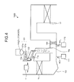
Fig. 4] Fig. 4 is a schematic diagram of an air pollution control apparatus according to a third embodiment of the present invention. - [
Fig. 5] Fig. 5 is a schematic diagram of an air pollution control apparatus of a coal combustion boiler. -
- 10
- coal combustion boiler
- 11,11a
- combustion gas
- 12
- furnace
- 13
- steam drum
- 14
- super heater
- 15
- economizer
- 15a
- economizer bypassing unit
- 16
- flue gas
- 17
- denitrator
- The present invention is explained below in detail with reference to the accompanying drawings. The present invention is not limited thereto. In addition, constituent elements in the following embodiments include those that can be easily assumed by those skilled in the art or that are substantially equivalent.
- An air pollution control apparatus according to a first embodiment of the present invention will be explained with reference to the drawings.
Fig. 1 is a schematic diagram of the air pollution control apparatus according to the first embodiment. InFig. 1 , the boiler system shown inFig. 5 and a boiler system of the present invention are the same, andFig. 1 depicts only a portion from a boiler to a denitrator. Like members are denoted by like reference numerals, and explanations thereof will be omitted.
As shown inFig. 1 , an airpollution control apparatus 100A according to the first embodiment reduces nitrogen oxides and mercury in theflue gas 16 discharged from a boiler (not shown) by an ammonia denitrating catalyst. The airpollution control apparatus 100A includes aneconomizer bypassing unit 15a that diverts high-temperature combustion gas 11 to a downstream side while bypassing theeconomizer 15 provided in agas flue 10a for thecombustion gas 11 from the boiler, provided with an ammonium-chloride supply unit 101 that supplies powdery ammonium chloride (NH4Cl) to theeconomizer bypassing unit 15a. The airpollution control apparatus 100A sublimates the ammonium chloride in an atmosphere at a high temperature of thecombustion gas 11, and supplies hydrogen chloride and ammonium into aflue 102.
Reference numeral 103 denotes a mixer that mixes hydrogen chloride (HCl) and ammonium (NH3) supplied into theflue gas 16. - With this configuration, NH4Cl powder is sprayed to the
economizer bypassing unit 15a, sublimated by high-temperature combustion gas 11a (550 to 650°C) that passes through theeconomizer bypassing unit 15a, and supplied as HCl and NH3 to theflue 102 for theflue gas 16 with which the bypassing unit is in communication. - In the boiler device, concentration of nitrogen oxides is varied. In such a case, urea ((H2N)2C=O) can be sprayed together with ammonium chloride to increase the supply of ammonia.
- In the first embodiment, the ammonium-
chloride supply unit 101 that supplies the ammonium chloride (NH4Cl) into theeconomizer bypassing unit 15a includes asilo 101a that temporarily stores the powdery ammonium chloride therein, afeeder 101b that supplies the stored ammonium chloride to acrusher 101c by a predetermined amount, and thecrusher 101c that crushes the supplied ammonium chloride into a predetermined particle diameter. - Because the sublimation of NH4Cl is an endothermic reaction, it is preferable that the temperature is higher. Thus, in the first embodiment, at the same time the NH4Cl powder is supplied from the
silo 101a by thefeeder 101b, thecrusher 101c is connected to crush the powder into fine particles so that the particles can easily be sublimated. The supply amount can be adjusted by thefeeder 101b, and controlled by an exit NOx monitor or Hg monitor. When the powdery ammonium chloride has the predetermined particle diameter or less, it is unnecessary to install thecrusher 101c. - Because the predetermined particle diameter of the ammonium chloride relates to a gas flow rate of the
combustion gas 11, it is necessary to determine the predetermined particle diameter according to the flow rate. For example, when a residence time of thecombustion gas 11a that passes through theeconomizer bypassing unit 15a is five seconds or less, it is preferable that the particle diameter of the ammonium chloride is 0.25 millimeter or less, and more preferably 0.2 millimeter or less. - NH3 decomposed by the ammonium chloride is used for reducing and denitrating NOx by the
denitrator 17, and HCl is used for oxidizing mercury, thereby reducing nitrogen oxides and mercury from the flue gas. The ammonium chloride can be charged into the boiler with a high temperature. However, because there is a possibility that NH3 is decomposed when the temperature is equal to or higher than its spontaneous ignition temperature of 651°C, it is necessary that the temperature thereof be 650°C or lower. - As shown with an air
pollution control apparatus 100B inFig. 2 , the powdery ammonium chloride can be supplied to a location close to an entrance of theeconomizer 15.
Aswitching unit 104 is provided so that the powdery ammonium chloride can be appropriately supplied to any one of the location close to the entrance of theeconomizer 15 and theeconomizer bypassing unit 15a, or both thereof.
For example, when the residence time of thecombustion gas 11 passing through theeconomizer 15 is two seconds or less, it is preferable that the particle diameter of the ammonium chloride be 0.15 millimeter or less, and more preferably 0.1 millimeter or less. - The concentrations of NH3 and HCl in the
flue 102 for theflue gas 16 are set such that a NH3/NOx molar ratio with respect to an NOx concentration of theflue gas 16 becomes 1 or less according to required denitration performance, and NH3 and HCl can be sprayed such that the concentrations become several tens to several hundreds ppm, preferably several tens to 200 ppm. - The amount of the
combustion gas 11 that passes through theeconomizer bypassing unit 15a is usually about several percent of theentire combustion gas 11. Therefore, it is preferable that the concentrations of NH3 and HCl in theeconomizer bypassing unit 15a is in a range of about 0.1 to several percent. This is because, when the concentrations are so high, the cost is increased and the cost efficiency is deteriorated. It is preferable that the Hg concentration of the flue gas be in a range of 0.1 to several tens µg/m3N, and is 1/1000 or less in the molar ratio with respect to the HCl concentration in the flue gas. - In the
economizer bypassing unit 15a of the boiler device through which the high-temperature combustion gas 11 upstream of thedenitrator 17 having the ammonia denitrating catalyst passes, HCl and NH3 are vaporized by the high-temperature (550 to 650°C)combustion gas 11 that passes through theeconomizer bypassing unit 15a by adding the powdery ammonium chloride (NH4Cl) Therefore, the vaporizer, the spray grid, and the storage tank that stores therein liquid HCl and NH3 can be omitted, unlike the conventional technique. - As described above, according to the present invention, the HCl and NH3 vaporizer, the spray grid and the storage tank can be omitted. In addition, because the powdery ammonium chloride (NH4Cl) is neutral salt and it is easy to handle the neutral salt, it is possible to largely reduce the costs required for legal permission and authorization for HCl and NH3 which are both hazardous materials, as well as the plant cost concerning safety management measures.
- Because the
combustion gas 11a that passes through theeconomizer bypassing unit 15a is used as a heat source for sublimation, another heat source is unnecessary. Because the temperature is higher (550°C) than the temperature of a denitrating catalyst (350 to 420°C) near upstream of the conventional denitrating catalyst apparatus, the sublimation rate is high, the required residence time can be shortened and thus, any additional sublimation equipment is not necessary. - Because the sublimation rate can be further increased by crushing the ammonium chloride powder using the
crusher 101c as needed, it is possible to prevent non-sublimated ammonium chloride from remaining or accumulating. - It is less expensive to supply the ammonium chloride alone as compared with the agent costs of HCl and NH3, which are separately supplied in the conventional technique, and the operation cost for a long term can be reduced.
- An air pollution control apparatus according to a second embodiment of the present invention will be explained with reference to the drawings.
Fig. 3 is a schematic diagram of the air pollution control apparatus according to the second embodiment. The same members as those of the air pollution control apparatus shown inFig. 1 are denoted by the same reference numerals, and explanations thereof will be omitted.
As shown inFig. 3 , an airpollution control apparatus 100C according to the second embodiment includes anHCl supply unit 111 that supplies HCl and an NH3 supply unit 112 that supplies NH3, to theflue 102 for theflue gas 16. - When the balance of the concentrations of nitrogen oxides and mercury in the flue gas discharged from a combustion device such as a boiler is different from a normal balance, a necessary amount of hydrochloric acid or ammonium is supplied into the
flue 102 to respond to the balance.
For example, when necessary HCl is greater than necessary NH3, HCl is sprayed from theHCl supply unit 111 and the ammonium chloride is sprayed. - On the other hand, when the necessary NH3 is smaller than the necessary HCl, NH3 is sprayed from the NH3 supply unit 112 and the ammonium chloride is sprayed.
At this time, urea ((H2N)2C=0) can be sprayed instead of ammonia. - With this configuration, because ammonia and hydrogen chloride are separately supplied in the second embodiment, even if the concentration of nitrogen oxides or mercury in the
flue gas 16 is varied, an appropriate operation can be taken. Third Embodiment - An air pollution control apparatus according to a third embodiment of the present invention will be explained with reference to the drawings.
Fig. 4 is a schematic diagram of the air pollution control apparatus according to the third embodiment. The same members as those of the air pollution control apparatus shown inFigs. 1 and3 are denoted by the same reference numerals, and explanations thereof will be omitted.
As shown inFig. 4 , an airpollution control apparatus 100D according to the third embodiment includes a rotary dryer (or rotary kiln) 120 as an evaporation unit that heats and evaporates the ammonium chloride supplied by thefeeder 101b, for example. - Because the
rotary dryer 120 is provided, the heating and evaporating operations for NH4Cl are facilitated, and it is possible to reliably sublimate and supply HCl and NH3 into the flue.
The sublimation step can be divided into two steps by using therotary dryer 120 in this manner, and it is possible to more reliably vaporize the ammonium chloride, and to reliably prevent the powder from remaining. - Tests were conducted using the air
pollution control apparatus 100C shown inFig. 3 .
The amount of thecombustion gas 11 from the boiler furnace is 2,400,000 Nm3/h, the temperature of thecombustion gas 11 at the entrance of the economizer is 600°C, and 2000 Nm3/h corresponding to 1% of thecombustion gas 11 is diverted into theeconomizer bypassing unit 15a. - In a test example 1, an NOx concentration at the entrance of the denitrator (SCR) 17 is 167 ppm, and a mercury concentration (Hg0) is 8 µg/m3N.
By supplying the powdery ammonium chloride by 875 kg/h, an NH3 supply concentration at the entrance of the denitrator (SCR) 17 is 150 ppm, an HCl supply concentration at the entrance of the denitrator (SCR) 17 is 150 ppm, the denitration ratio is 90%, and a mercury oxidation ratio is 97%. - These results are shown in Table 1.
[Table 1] Test example 1 Test example 2 Test example 3 Test example 4 Flue gas amount M3N/ h 2,400,000 2,400,000 2,400,000 2,400,000 Flue gas temperature at economizer entrance C° 600 600 600 600 Amount of gas bypassing economizer M3N/ h 24,000 24,000 24,000 24,000 NH4Cl supply amount Kg/h 875 875 875 420 NH3 supply amount Kg/h 0 319 0 0 Urea supply amount Kg/h 0 0 530 0 HCl supply amount Kg/h 0 0 0 304 NH3 concentration at entrance of denitrator Ppm 150 315 315 72 HCl concentration at entrance of denitrator Ppm 150 150 150 150 NOx concentration at entrance of denitrator Ppm 167 350 350 80 NH3/NOx ratio - 0.9 0.9 0.9 0.9 Temperature at entrance of denitrator C° 370 370 370 370 Hg0 concentration at entrance of denitrator µg/ m3N 8 8 8 8 Hg2+ concentration at entrance of denitrator µg/ m3N 2 2 2 2 Hg0 concentration at exit of denitrator µg/ m3N 0.24 0.4 0.4 0.16 Hg2+ concentration at exit of denitrator µg/ m3N 9.76 9.6 9.6 9.84 Hg0 oxidation ratio % 97 95 95 98 Denitration ratio % 90 90 90 90 - In a test example 2, the NOx concentration at the entrance of the denitrator (SCR) 17 is increased as high as 350 ppm. The mercury concentration (Hg0) is the same and is 8 µg/m3N.
When the powdery ammonium chloride is supplied by 875 kg/h and ammonia is supplied into theflue 102 by 319 kg/h, the NH3 supply concentration at the entrance of the denitrator (SCR) 17 became 315 ppm, the HCl supply concentration at the entrance of the denitrator (SCR) 17 became 150 ppm, the denitration ratio is 90%, and the mercury oxidation ratio is 95%.
In the test example 2, because the nitrogen oxides concentration is high, the mercy oxidation ratio is slightly reduced. - In a test example 3, the NOx concentration at the entrance of the denitrator (SCR) 17 is increased as high as 350 ppm. The mercury concentration (Hg0) is the same and is 8 µg/m3N.
The powdery ammonium chloride is supplied by 875 kg/h, and urea is supplied into theflue gas flue 102 by 530 kg/h. With this configuration, the NH3 supply concentration at the entrance of the denitrator (SCR) 17 became 315 ppm, the HCl supply concentration at the entrance of the denitrator (SCR) 17 became 150 ppm, the denitration ratio is 90%, and the mercury oxidation ratio is 95%.
Even if the urea is supplied instead of separately supplying the ammonia, the denitration ratio is not reduced. In the test example 3 also, because the concentration of nitrogen oxides is high, the mercury oxidation ratio was slightly reduced. - In a test example 4, the NOx concentration at the entrance of the denitrator (SCR) 17 is reduced as low as 80 ppm. The mercury concentration (Hg0) is the same and is 8 µg/m3N.
The powdery ammonium chloride is supplied by 420 kg/h and HCl is supplied by 304 kg/h. With this configuration, the NH3 supply concentration at the entrance of the denitrator (SCR) 17 became 72 ppm, the HCl supply concentration at the entrance of the denitrator (SCR) 17 became 150 ppm, the denitration ratio is 90%, and the mercury oxidation ratio is 98%.
In the test example 4, because the nitrogen oxides concentration is low, the mercury oxidation ratio is enhanced. - By adding the powdery ammonium chloride (NH4Cl) according to the present invention as described above, HCl and NH3 are evaporated by high-temperature (550 to 650°C) combustion gas passing through the economizer or the economizer bypassing unit. With this configuration, omission of constituent elements in air pollution control apparatus can be achieved.
Claims (7)
- An air pollution control apparatus that reduces nitrogen oxides and oxidizes mercury in flue gas from a boiler by using an ammonia denitrating catalyst, the air pollution control apparatus comprising:an ammonium-chloride supply unit that supplies powdery ammonium chloride to a location near an entrance of an economizer provided in a flue of the boiler or to an economizer bypassing unit, or both of them, whereinthe supplied powdery ammonium chloride is sublimated by combustion gas, and hydrogen chloride and ammonium are supplied into the flue.
- The air pollution control apparatus according to claim 1, wherein a particle diameter of the powdery ammonium chloride is 0.25 millimeter or less.
- The air pollution control apparatus according to claim 1, wherein any one of an HCl supply unit and an NH3 supply unit, or both of them are provided downstream of the economizer.
- The air pollution control apparatus according to claim 1, wherein the ammonium-chloride supply unit includes a crushing unit that crushes solid ammonium chloride.
- The air pollution control apparatus according to claim 1, further comprising a vaporizer that heats and vaporizes the ammonium chloride supplied from the ammonium-chloride supply unit.
- The air pollution control apparatus according to claim 1, further comprising a vaporizer that heats and vaporizes the ammonium chloride supplied from the ammonium-chloride supply unit, wherein
a particle diameter of the powdery ammonium chloride is 0.25 millimeter or less. - An air pollution control method for reducing nitrogen oxides and oxidizing mercury in flue gas from a boiler by using an ammonia denitrating catalyst, the air pollution control method comprising:supplying powdery ammonium chloride to a location near an entrance of an economizer provided in a flue of a boiler device or to an economizer bypassing unit, or both of them;sublimating the ammonium chloride in an atmosphere at a temperature of combustion gas at a supply location; andsupplying hydrogen chloride and ammonium into the flue.
Priority Applications (1)
| Application Number | Priority Date | Filing Date | Title |
|---|---|---|---|
| PL07790937T PL2133134T3 (en) | 2007-03-09 | 2007-07-18 | Apparatus and method for treating discharge gas |
Applications Claiming Priority (2)
| Application Number | Priority Date | Filing Date | Title |
|---|---|---|---|
| JP2007060729A JP4719171B2 (en) | 2007-03-09 | 2007-03-09 | Exhaust gas treatment apparatus and method |
| PCT/JP2007/064183 WO2008111240A1 (en) | 2007-03-09 | 2007-07-18 | Apparatus and method for treating discharge gas |
Publications (3)
| Publication Number | Publication Date |
|---|---|
| EP2133134A1 true EP2133134A1 (en) | 2009-12-16 |
| EP2133134A4 EP2133134A4 (en) | 2011-06-08 |
| EP2133134B1 EP2133134B1 (en) | 2014-07-09 |
Family
ID=39759186
Family Applications (1)
| Application Number | Title | Priority Date | Filing Date |
|---|---|---|---|
| EP07790937.2A Active EP2133134B1 (en) | 2007-03-09 | 2007-07-18 | Apparatus and method for treating discharge gas |
Country Status (9)
| Country | Link |
|---|---|
| US (1) | US7887768B2 (en) |
| EP (1) | EP2133134B1 (en) |
| JP (1) | JP4719171B2 (en) |
| CN (1) | CN101622056B (en) |
| CA (1) | CA2674330C (en) |
| DK (1) | DK2133134T3 (en) |
| ES (1) | ES2500440T3 (en) |
| PL (1) | PL2133134T3 (en) |
| WO (1) | WO2008111240A1 (en) |
Families Citing this family (47)
| Publication number | Priority date | Publication date | Assignee | Title |
|---|---|---|---|---|
| JP5118474B2 (en) * | 2007-12-26 | 2013-01-16 | 三菱重工業株式会社 | Exhaust gas treatment equipment |
| JP5517460B2 (en) * | 2009-01-19 | 2014-06-11 | バブコック日立株式会社 | Denitration equipment |
| JP5456038B2 (en) * | 2009-06-17 | 2014-03-26 | 三菱重工業株式会社 | Mercury removal system and mercury removal method for mercury-containing high-temperature exhaust gas |
| WO2010146670A1 (en) | 2009-06-17 | 2010-12-23 | 三菱重工業株式会社 | System for removing mercury and method of removing mercury from mercury-containing high-temperature discharge gas |
| WO2010146672A1 (en) * | 2009-06-17 | 2010-12-23 | 三菱重工業株式会社 | System for removing mercury and method of removing mercury from mercury-containing high-temperature discharge gas |
| US8071036B2 (en) | 2009-07-06 | 2011-12-06 | Mitsubishi Heavy Industries, Ltd. | Mercury reduction system |
| US7901645B2 (en) | 2009-07-06 | 2011-03-08 | Mitsubishi Heavy Industries, Ltd. | Mercury reduction system and mercury reduction method of flue gas containing mercury |
| US7906090B2 (en) | 2009-07-06 | 2011-03-15 | Mitsubishi Heavy Industries, Ltd. | Mercury reduction system and mercury reduction method of flue gas containing mercury |
| JP5558042B2 (en) | 2009-08-05 | 2014-07-23 | 三菱重工業株式会社 | Exhaust gas treatment device and mercury removal method of exhaust gas |
| JP5523807B2 (en) | 2009-08-05 | 2014-06-18 | 三菱重工業株式会社 | Exhaust gas treatment equipment |
| JP2011031212A (en) * | 2009-08-05 | 2011-02-17 | Mitsubishi Heavy Ind Ltd | System and method for removing mercury in exhaust gas |
| JP5626220B2 (en) | 2009-11-16 | 2014-11-19 | 株式会社Ihi | Mercury removal apparatus and mercury removal method |
| JP5693061B2 (en) * | 2010-06-30 | 2015-04-01 | 三菱重工業株式会社 | Exhaust gas treatment equipment |
| US9388978B1 (en) | 2012-12-21 | 2016-07-12 | Mitsubishi Hitachi Power Systems Americas, Inc. | Methods and systems for controlling gas temperatures |
| CN103170236B (en) * | 2013-03-01 | 2015-04-22 | 广东电网公司电力科学研究院 | Intelligent demercuration addition agent adding system for coal-fired power plant |
| CN103423757B (en) * | 2013-07-31 | 2016-12-28 | 华北电力大学(保定) | A device and method for removing mercury from flue gas by using polyvinyl chloride and boiler fly ash |
| USD764597S1 (en) * | 2015-06-12 | 2016-08-23 | Microsoft Corporation | Thumbstick attachment for a controller |
| USD767038S1 (en) | 2015-06-12 | 2016-09-20 | Microsoft Corporation | Controller with removable thumbstick attachment |
| USD767684S1 (en) | 2015-06-12 | 2016-09-27 | Microsoft Corporation | Controller with a removable directional pad |
| USD773561S1 (en) | 2015-06-12 | 2016-12-06 | Microsoft Corporation | Controller with removable thumbstick attachment |
| USD772988S1 (en) | 2015-06-12 | 2016-11-29 | Microsoft Corporation | Controller |
| USD766376S1 (en) | 2015-06-12 | 2016-09-13 | Microsoft Corporation | Controller with removable directional pad |
| USD774143S1 (en) * | 2015-06-12 | 2016-12-13 | Microsoft Corporation | Thumbstick attachment for a controller |
| USD772987S1 (en) | 2015-06-12 | 2016-11-29 | Microsoft Corporation | Controller |
| USD763967S1 (en) * | 2015-06-12 | 2016-08-16 | Microsoft Corporation | Thumbstick attachment for a controller |
| USD774596S1 (en) | 2015-06-15 | 2016-12-20 | Microsoft Corporation | Controller |
| USD784335S1 (en) | 2015-10-29 | 2017-04-18 | Microsoft Corporation | Controller with removeable paddles |
| USD784989S1 (en) | 2015-10-29 | 2017-04-25 | Microsoft Corporation | Controller |
| USD794026S1 (en) | 2015-10-29 | 2017-08-08 | Microsoft Corporation | Set of paddles for a controller |
| USD784988S1 (en) | 2015-10-29 | 2017-04-25 | Microsoft Corporation | Controller with removeable thumbstick attachment |
| USD794024S1 (en) | 2015-10-29 | 2017-08-08 | Microsoft Corporation | Directional pad for a controller |
| USD784986S1 (en) | 2015-10-29 | 2017-04-25 | Microsoft Corporation | Thumbstick for a controller |
| USD785624S1 (en) | 2015-10-29 | 2017-05-02 | Microsoft Corporation | Battery compartment for a controller |
| USD794717S1 (en) | 2016-05-13 | 2017-08-15 | Microsoft Corporation | Controller |
| USD799599S1 (en) | 2016-05-13 | 2017-10-10 | Microsoft Corporation | Controller |
| USD794129S1 (en) | 2016-05-13 | 2017-08-08 | Microsoft Corporation | Controller |
| USD795350S1 (en) | 2016-06-09 | 2017-08-22 | Microsoft Corporation | Controller |
| USD795351S1 (en) | 2016-06-09 | 2017-08-22 | Microsoft Corporation | Controller |
| USD795960S1 (en) | 2016-07-14 | 2017-08-29 | Microsoft Corporation | Controller |
| USD816170S1 (en) | 2017-04-06 | 2018-04-24 | Microsoft Corporation | Controller |
| USD825005S1 (en) | 2017-04-06 | 2018-08-07 | Microsoft Corporation | Controller |
| USD816773S1 (en) | 2017-04-06 | 2018-05-01 | Microsoft Corporation | Controller |
| USD872183S1 (en) | 2018-06-08 | 2020-01-07 | Microsoft Corporation | Controller |
| CN109603456B (en) * | 2019-01-25 | 2021-08-03 | 米凯利科技(北京)有限公司 | Dry flue gas demercuration system using halide crystals |
| CN110227345B (en) * | 2019-06-27 | 2023-12-29 | 国网吉林省电力有限公司电力科学研究院 | A wide-load denitration system and control method suitable for subcritical thermal power units |
| KR102201771B1 (en) * | 2019-12-26 | 2021-01-13 | 대구대학교 산학협력단 | Ammonium chloride Injection Device for Elemental Mercury Oxidation in SCR Reactor and Injection Method using the same |
| CN112844001B (en) * | 2021-02-02 | 2024-11-15 | 浙江菲达环保科技股份有限公司 | A solid powder dispersion device for dry desulfurization |
Family Cites Families (10)
| Publication number | Priority date | Publication date | Assignee | Title |
|---|---|---|---|---|
| JPS5658522A (en) * | 1979-10-18 | 1981-05-21 | Tokyo Electric Power Co Inc:The | Denitrification method of exhaust gas |
| JPS61185320A (en) * | 1985-02-14 | 1986-08-19 | Mitsubishi Heavy Ind Ltd | Purification of exhaust gas |
| JPH02241520A (en) * | 1989-03-16 | 1990-09-26 | Babcock Hitachi Kk | Waste gas denitration apparatus |
| JP3935547B2 (en) | 1997-02-19 | 2007-06-27 | 三菱重工業株式会社 | Exhaust gas treatment method and exhaust gas treatment apparatus |
| US6960329B2 (en) * | 2002-03-12 | 2005-11-01 | Foster Wheeler Energy Corporation | Method and apparatus for removing mercury species from hot flue gas |
| JP4395315B2 (en) * | 2003-04-11 | 2010-01-06 | 三菱重工業株式会社 | Method and system for removing mercury from exhaust gas |
| US7708964B2 (en) * | 2004-12-02 | 2010-05-04 | Battelle Energy Alliance, Llc | Oil shale derived pollutant control materials and methods and apparatuses for producing and utilizing the same |
| JP4838579B2 (en) * | 2005-12-21 | 2011-12-14 | 三菱重工業株式会社 | Mercury removal system and mercury removal method |
| US20070160517A1 (en) * | 2005-12-22 | 2007-07-12 | Foster Wheeler Energy Corporation | Catalyst, a method of using a catalyst, and an arrangement including a catalyst, for controlling NO and/or CO emissions from a combustion system without using external reagent |
| JP4388542B2 (en) * | 2006-12-07 | 2009-12-24 | 三菱重工業株式会社 | Mercury removal method and mercury removal system |
-
2007
- 2007-03-09 JP JP2007060729A patent/JP4719171B2/en active Active
- 2007-07-18 DK DK07790937.2T patent/DK2133134T3/en active
- 2007-07-18 ES ES07790937.2T patent/ES2500440T3/en active Active
- 2007-07-18 WO PCT/JP2007/064183 patent/WO2008111240A1/en not_active Ceased
- 2007-07-18 CN CN2007800520216A patent/CN101622056B/en active Active
- 2007-07-18 EP EP07790937.2A patent/EP2133134B1/en active Active
- 2007-07-18 CA CA2674330A patent/CA2674330C/en not_active Expired - Fee Related
- 2007-07-18 US US12/522,044 patent/US7887768B2/en active Active
- 2007-07-18 PL PL07790937T patent/PL2133134T3/en unknown
Also Published As
| Publication number | Publication date |
|---|---|
| JP2008221087A (en) | 2008-09-25 |
| JP4719171B2 (en) | 2011-07-06 |
| EP2133134A4 (en) | 2011-06-08 |
| CN101622056B (en) | 2013-01-16 |
| CA2674330C (en) | 2011-05-10 |
| WO2008111240A1 (en) | 2008-09-18 |
| US7887768B2 (en) | 2011-02-15 |
| CN101622056A (en) | 2010-01-06 |
| EP2133134B1 (en) | 2014-07-09 |
| PL2133134T3 (en) | 2014-12-31 |
| ES2500440T3 (en) | 2014-09-30 |
| US20100074818A1 (en) | 2010-03-25 |
| DK2133134T3 (en) | 2014-10-13 |
| CA2674330A1 (en) | 2008-09-18 |
Similar Documents
| Publication | Publication Date | Title |
|---|---|---|
| EP2133134B1 (en) | Apparatus and method for treating discharge gas | |
| EP2223734B1 (en) | Exhaust gas treating apparatus and method | |
| US7906090B2 (en) | Mercury reduction system and mercury reduction method of flue gas containing mercury | |
| EP2444143B1 (en) | System for removing mercury and method of removing mercury from mercury-containing high-temperature discharge gas | |
| JP4838579B2 (en) | Mercury removal system and mercury removal method | |
| US7976800B1 (en) | Integrated exhaust gas cooling system and method | |
| US6146605A (en) | Combined SCR/SNCR process | |
| US7901645B2 (en) | Mercury reduction system and mercury reduction method of flue gas containing mercury | |
| KR20170124106A (en) | Apparatus and method for evaporating waste water and reducing acid gas emissions | |
| CA2764121C (en) | Mercury reduction system and mercury reduction method of flue gas containing mercury | |
| JP2012213744A (en) | Apparatus and method for treating exhaust gas and coal upgrading process facility | |
| KR100437875B1 (en) | NOx reduction system by selective catalytic reduction available for urea as reducing agent | |
| US20110002827A1 (en) | Mercury reduction system and mercury reduction method of flue gas containing mercury | |
| US6060030A (en) | Detached plume abatement method | |
| WO2010146672A1 (en) | System for removing mercury and method of removing mercury from mercury-containing high-temperature discharge gas | |
| JP2000000434A (en) | Denitration apparatus and denitration method | |
| KR20250103018A (en) | Apparatus for ammonia production having multiple-tube structure | |
| Chmielewski | Electron beam gaseous pollutants treatment | |
| KR20260048974A (en) | Oxygen-enriched combustion method and system using flue gas | |
| JPH02258018A (en) | Denitrification of combustion gas | |
| JPH09173780A (en) | Portable organic halogen compound decomposition equipment |
Legal Events
| Date | Code | Title | Description |
|---|---|---|---|
| PUAI | Public reference made under article 153(3) epc to a published international application that has entered the european phase |
Free format text: ORIGINAL CODE: 0009012 |
|
| 17P | Request for examination filed |
Effective date: 20090811 |
|
| AK | Designated contracting states |
Kind code of ref document: A1 Designated state(s): AT BE BG CH CY CZ DE DK EE ES FI FR GB GR HU IE IS IT LI LT LU LV MC MT NL PL PT RO SE SI SK TR |
|
| RIN1 | Information on inventor provided before grant (corrected) |
Inventor name: KIYOSAWA, MASASHI Inventor name: OBAYASHI, YOSHIAKI Inventor name: NOCHI, KATSUMI Inventor name: HONJO, SHINTARO |
|
| DAX | Request for extension of the european patent (deleted) | ||
| A4 | Supplementary search report drawn up and despatched |
Effective date: 20110510 |
|
| RIC1 | Information provided on ipc code assigned before grant |
Ipc: B01D 53/64 20060101ALI20110503BHEP Ipc: B01D 53/86 20060101AFI20081002BHEP Ipc: F23J 15/00 20060101ALI20110503BHEP |
|
| 17Q | First examination report despatched |
Effective date: 20130502 |
|
| RIC1 | Information provided on ipc code assigned before grant |
Ipc: F23L 15/04 20060101ALI20131111BHEP Ipc: F23J 15/02 20060101ALI20131111BHEP Ipc: B01D 53/64 20060101ALI20131111BHEP Ipc: F23J 15/00 20060101ALI20131111BHEP Ipc: B01D 53/86 20060101AFI20131111BHEP |
|
| GRAP | Despatch of communication of intention to grant a patent |
Free format text: ORIGINAL CODE: EPIDOSNIGR1 |
|
| INTG | Intention to grant announced |
Effective date: 20140108 |
|
| GRAS | Grant fee paid |
Free format text: ORIGINAL CODE: EPIDOSNIGR3 |
|
| GRAA | (expected) grant |
Free format text: ORIGINAL CODE: 0009210 |
|
| AK | Designated contracting states |
Kind code of ref document: B1 Designated state(s): AT BE BG CH CY CZ DE DK EE ES FI FR GB GR HU IE IS IT LI LT LU LV MC MT NL PL PT RO SE SI SK TR |
|
| REG | Reference to a national code |
Ref country code: GB Ref legal event code: FG4D |
|
| REG | Reference to a national code |
Ref country code: AT Ref legal event code: REF Ref document number: 676353 Country of ref document: AT Kind code of ref document: T Effective date: 20140715 Ref country code: CH Ref legal event code: EP |
|
| REG | Reference to a national code |
Ref country code: IE Ref legal event code: FG4D |
|
| REG | Reference to a national code |
Ref country code: DE Ref legal event code: R096 Ref document number: 602007037568 Country of ref document: DE Effective date: 20140821 |
|
| REG | Reference to a national code |
Ref country code: ES Ref legal event code: FG2A Ref document number: 2500440 Country of ref document: ES Kind code of ref document: T3 Effective date: 20140930 |
|
| REG | Reference to a national code |
Ref country code: DK Ref legal event code: T3 Effective date: 20141007 |
|
| REG | Reference to a national code |
Ref country code: NL Ref legal event code: VDEP Effective date: 20140709 |
|
| REG | Reference to a national code |
Ref country code: LT Ref legal event code: MG4D |
|
| REG | Reference to a national code |
Ref country code: PL Ref legal event code: T3 |
|
| PG25 | Lapsed in a contracting state [announced via postgrant information from national office to epo] |
Ref country code: FI Free format text: LAPSE BECAUSE OF FAILURE TO SUBMIT A TRANSLATION OF THE DESCRIPTION OR TO PAY THE FEE WITHIN THE PRESCRIBED TIME-LIMIT Effective date: 20140709 Ref country code: BG Free format text: LAPSE BECAUSE OF FAILURE TO SUBMIT A TRANSLATION OF THE DESCRIPTION OR TO PAY THE FEE WITHIN THE PRESCRIBED TIME-LIMIT Effective date: 20141009 Ref country code: PT Free format text: LAPSE BECAUSE OF FAILURE TO SUBMIT A TRANSLATION OF THE DESCRIPTION OR TO PAY THE FEE WITHIN THE PRESCRIBED TIME-LIMIT Effective date: 20141110 Ref country code: LT Free format text: LAPSE BECAUSE OF FAILURE TO SUBMIT A TRANSLATION OF THE DESCRIPTION OR TO PAY THE FEE WITHIN THE PRESCRIBED TIME-LIMIT Effective date: 20140709 Ref country code: SE Free format text: LAPSE BECAUSE OF FAILURE TO SUBMIT A TRANSLATION OF THE DESCRIPTION OR TO PAY THE FEE WITHIN THE PRESCRIBED TIME-LIMIT Effective date: 20140709 Ref country code: GR Free format text: LAPSE BECAUSE OF FAILURE TO SUBMIT A TRANSLATION OF THE DESCRIPTION OR TO PAY THE FEE WITHIN THE PRESCRIBED TIME-LIMIT Effective date: 20141010 |
|
| PG25 | Lapsed in a contracting state [announced via postgrant information from national office to epo] |
Ref country code: NL Free format text: LAPSE BECAUSE OF FAILURE TO SUBMIT A TRANSLATION OF THE DESCRIPTION OR TO PAY THE FEE WITHIN THE PRESCRIBED TIME-LIMIT Effective date: 20140709 Ref country code: LV Free format text: LAPSE BECAUSE OF FAILURE TO SUBMIT A TRANSLATION OF THE DESCRIPTION OR TO PAY THE FEE WITHIN THE PRESCRIBED TIME-LIMIT Effective date: 20140709 Ref country code: CY Free format text: LAPSE BECAUSE OF FAILURE TO SUBMIT A TRANSLATION OF THE DESCRIPTION OR TO PAY THE FEE WITHIN THE PRESCRIBED TIME-LIMIT Effective date: 20140709 Ref country code: IS Free format text: LAPSE BECAUSE OF FAILURE TO SUBMIT A TRANSLATION OF THE DESCRIPTION OR TO PAY THE FEE WITHIN THE PRESCRIBED TIME-LIMIT Effective date: 20141109 |
|
| REG | Reference to a national code |
Ref country code: CH Ref legal event code: PL |
|
| REG | Reference to a national code |
Ref country code: DE Ref legal event code: R097 Ref document number: 602007037568 Country of ref document: DE |
|
| REG | Reference to a national code |
Ref country code: IE Ref legal event code: MM4A |
|
| PG25 | Lapsed in a contracting state [announced via postgrant information from national office to epo] |
Ref country code: EE Free format text: LAPSE BECAUSE OF FAILURE TO SUBMIT A TRANSLATION OF THE DESCRIPTION OR TO PAY THE FEE WITHIN THE PRESCRIBED TIME-LIMIT Effective date: 20140709 Ref country code: MC Free format text: LAPSE BECAUSE OF FAILURE TO SUBMIT A TRANSLATION OF THE DESCRIPTION OR TO PAY THE FEE WITHIN THE PRESCRIBED TIME-LIMIT Effective date: 20140709 Ref country code: CH Free format text: LAPSE BECAUSE OF NON-PAYMENT OF DUE FEES Effective date: 20140731 Ref country code: SK Free format text: LAPSE BECAUSE OF FAILURE TO SUBMIT A TRANSLATION OF THE DESCRIPTION OR TO PAY THE FEE WITHIN THE PRESCRIBED TIME-LIMIT Effective date: 20140709 Ref country code: RO Free format text: LAPSE BECAUSE OF FAILURE TO SUBMIT A TRANSLATION OF THE DESCRIPTION OR TO PAY THE FEE WITHIN THE PRESCRIBED TIME-LIMIT Effective date: 20140709 Ref country code: CZ Free format text: LAPSE BECAUSE OF FAILURE TO SUBMIT A TRANSLATION OF THE DESCRIPTION OR TO PAY THE FEE WITHIN THE PRESCRIBED TIME-LIMIT Effective date: 20140709 Ref country code: LI Free format text: LAPSE BECAUSE OF NON-PAYMENT OF DUE FEES Effective date: 20140731 |
|
| PLBE | No opposition filed within time limit |
Free format text: ORIGINAL CODE: 0009261 |
|
| STAA | Information on the status of an ep patent application or granted ep patent |
Free format text: STATUS: NO OPPOSITION FILED WITHIN TIME LIMIT |
|
| REG | Reference to a national code |
Ref country code: FR Ref legal event code: ST Effective date: 20150511 |
|
| 26N | No opposition filed |
Effective date: 20150410 |
|
| GBPC | Gb: european patent ceased through non-payment of renewal fee |
Effective date: 20141009 |
|
| PG25 | Lapsed in a contracting state [announced via postgrant information from national office to epo] |
Ref country code: GB Free format text: LAPSE BECAUSE OF NON-PAYMENT OF DUE FEES Effective date: 20141009 |
|
| PG25 | Lapsed in a contracting state [announced via postgrant information from national office to epo] |
Ref country code: IE Free format text: LAPSE BECAUSE OF NON-PAYMENT OF DUE FEES Effective date: 20140718 Ref country code: FR Free format text: LAPSE BECAUSE OF NON-PAYMENT OF DUE FEES Effective date: 20140909 |
|
| PG25 | Lapsed in a contracting state [announced via postgrant information from national office to epo] |
Ref country code: SI Free format text: LAPSE BECAUSE OF FAILURE TO SUBMIT A TRANSLATION OF THE DESCRIPTION OR TO PAY THE FEE WITHIN THE PRESCRIBED TIME-LIMIT Effective date: 20140709 |
|
| PG25 | Lapsed in a contracting state [announced via postgrant information from national office to epo] |
Ref country code: MT Free format text: LAPSE BECAUSE OF FAILURE TO SUBMIT A TRANSLATION OF THE DESCRIPTION OR TO PAY THE FEE WITHIN THE PRESCRIBED TIME-LIMIT Effective date: 20140709 |
|
| PG25 | Lapsed in a contracting state [announced via postgrant information from national office to epo] |
Ref country code: BE Free format text: LAPSE BECAUSE OF FAILURE TO SUBMIT A TRANSLATION OF THE DESCRIPTION OR TO PAY THE FEE WITHIN THE PRESCRIBED TIME-LIMIT Effective date: 20140709 Ref country code: TR Free format text: LAPSE BECAUSE OF FAILURE TO SUBMIT A TRANSLATION OF THE DESCRIPTION OR TO PAY THE FEE WITHIN THE PRESCRIBED TIME-LIMIT Effective date: 20140709 Ref country code: HU Free format text: LAPSE BECAUSE OF FAILURE TO SUBMIT A TRANSLATION OF THE DESCRIPTION OR TO PAY THE FEE WITHIN THE PRESCRIBED TIME-LIMIT; INVALID AB INITIO Effective date: 20070718 Ref country code: LU Free format text: LAPSE BECAUSE OF NON-PAYMENT OF DUE FEES Effective date: 20140718 |
|
| PGFP | Annual fee paid to national office [announced via postgrant information from national office to epo] |
Ref country code: ES Payment date: 20200803 Year of fee payment: 14 Ref country code: DK Payment date: 20200710 Year of fee payment: 14 Ref country code: DE Payment date: 20200707 Year of fee payment: 14 |
|
| PGFP | Annual fee paid to national office [announced via postgrant information from national office to epo] |
Ref country code: IT Payment date: 20200610 Year of fee payment: 14 |
|
| REG | Reference to a national code |
Ref country code: DE Ref legal event code: R119 Ref document number: 602007037568 Country of ref document: DE |
|
| REG | Reference to a national code |
Ref country code: DK Ref legal event code: EBP Effective date: 20210731 |
|
| PG25 | Lapsed in a contracting state [announced via postgrant information from national office to epo] |
Ref country code: DE Free format text: LAPSE BECAUSE OF NON-PAYMENT OF DUE FEES Effective date: 20220201 |
|
| PG25 | Lapsed in a contracting state [announced via postgrant information from national office to epo] |
Ref country code: IT Free format text: LAPSE BECAUSE OF NON-PAYMENT OF DUE FEES Effective date: 20210718 Ref country code: DK Free format text: LAPSE BECAUSE OF NON-PAYMENT OF DUE FEES Effective date: 20210731 |
|
| REG | Reference to a national code |
Ref country code: ES Ref legal event code: FD2A Effective date: 20220906 |
|
| PG25 | Lapsed in a contracting state [announced via postgrant information from national office to epo] |
Ref country code: ES Free format text: LAPSE BECAUSE OF NON-PAYMENT OF DUE FEES Effective date: 20210719 |
|
| PGFP | Annual fee paid to national office [announced via postgrant information from national office to epo] |
Ref country code: PL Payment date: 20250527 Year of fee payment: 19 |
|
| PGFP | Annual fee paid to national office [announced via postgrant information from national office to epo] |
Ref country code: AT Payment date: 20250625 Year of fee payment: 19 |