EP2132472B1 - Systeme und verfahren für feldinitiierte flüssigkeitsregulierungstests - Google Patents
Systeme und verfahren für feldinitiierte flüssigkeitsregulierungstests Download PDFInfo
- Publication number
- EP2132472B1 EP2132472B1 EP20080732841 EP08732841A EP2132472B1 EP 2132472 B1 EP2132472 B1 EP 2132472B1 EP 20080732841 EP20080732841 EP 20080732841 EP 08732841 A EP08732841 A EP 08732841A EP 2132472 B1 EP2132472 B1 EP 2132472B1
- Authority
- EP
- European Patent Office
- Prior art keywords
- control signal
- fluid regulator
- signal
- field test
- fluid
- Prior art date
- Legal status (The legal status is an assumption and is not a legal conclusion. Google has not performed a legal analysis and makes no representation as to the accuracy of the status listed.)
- Not-in-force
Links
- 239000012530 fluid Substances 0.000 title claims abstract description 385
- 238000012360 testing method Methods 0.000 title claims abstract description 341
- 238000000034 method Methods 0.000 title claims abstract description 61
- 230000033228 biological regulation Effects 0.000 title claims description 20
- 230000008569 process Effects 0.000 title abstract description 47
- 239000003999 initiator Substances 0.000 claims abstract description 158
- 230000004913 activation Effects 0.000 claims abstract description 30
- 230000004075 alteration Effects 0.000 claims abstract description 10
- 239000003607 modifier Substances 0.000 claims description 50
- 238000004891 communication Methods 0.000 claims description 19
- 230000000977 initiatory effect Effects 0.000 claims description 16
- 238000012544 monitoring process Methods 0.000 claims description 16
- 230000036541 health Effects 0.000 claims description 15
- 230000036961 partial effect Effects 0.000 claims description 15
- 230000004044 response Effects 0.000 claims description 15
- 238000005286 illumination Methods 0.000 claims description 14
- 230000000007 visual effect Effects 0.000 claims description 5
- 238000001514 detection method Methods 0.000 claims description 3
- 230000003213 activating effect Effects 0.000 claims description 2
- 230000001105 regulatory effect Effects 0.000 abstract description 81
- 238000010586 diagram Methods 0.000 description 4
- 239000007789 gas Substances 0.000 description 4
- 238000009434 installation Methods 0.000 description 4
- VNWKTOKETHGBQD-UHFFFAOYSA-N methane Chemical compound C VNWKTOKETHGBQD-UHFFFAOYSA-N 0.000 description 4
- 230000009471 action Effects 0.000 description 3
- 238000004458 analytical method Methods 0.000 description 3
- 239000003990 capacitor Substances 0.000 description 3
- 230000007423 decrease Effects 0.000 description 3
- 230000003247 decreasing effect Effects 0.000 description 3
- 238000004519 manufacturing process Methods 0.000 description 3
- 230000004048 modification Effects 0.000 description 3
- 238000012986 modification Methods 0.000 description 3
- 230000015556 catabolic process Effects 0.000 description 2
- 230000008878 coupling Effects 0.000 description 2
- 238000010168 coupling process Methods 0.000 description 2
- 238000005859 coupling reaction Methods 0.000 description 2
- 238000006731 degradation reaction Methods 0.000 description 2
- 230000002401 inhibitory effect Effects 0.000 description 2
- 238000012423 maintenance Methods 0.000 description 2
- 239000003345 natural gas Substances 0.000 description 2
- 230000001960 triggered effect Effects 0.000 description 2
- 238000013022 venting Methods 0.000 description 2
- 238000001134 F-test Methods 0.000 description 1
- 241000699670 Mus sp. Species 0.000 description 1
- 230000005856 abnormality Effects 0.000 description 1
- 238000007792 addition Methods 0.000 description 1
- 230000003321 amplification Effects 0.000 description 1
- 230000008901 benefit Effects 0.000 description 1
- 230000008859 change Effects 0.000 description 1
- 238000006243 chemical reaction Methods 0.000 description 1
- 238000012217 deletion Methods 0.000 description 1
- 230000037430 deletion Effects 0.000 description 1
- 230000000881 depressing effect Effects 0.000 description 1
- 230000000994 depressogenic effect Effects 0.000 description 1
- 238000004880 explosion Methods 0.000 description 1
- 230000005669 field effect Effects 0.000 description 1
- 230000008014 freezing Effects 0.000 description 1
- 238000007710 freezing Methods 0.000 description 1
- -1 gasses Substances 0.000 description 1
- 230000005764 inhibitory process Effects 0.000 description 1
- 230000003993 interaction Effects 0.000 description 1
- 230000000670 limiting effect Effects 0.000 description 1
- 239000007788 liquid Substances 0.000 description 1
- 239000004973 liquid crystal related substance Substances 0.000 description 1
- 230000007257 malfunction Effects 0.000 description 1
- 239000000463 material Substances 0.000 description 1
- 230000007246 mechanism Effects 0.000 description 1
- 229910044991 metal oxide Inorganic materials 0.000 description 1
- 150000004706 metal oxides Chemical class 0.000 description 1
- 238000003199 nucleic acid amplification method Methods 0.000 description 1
- 230000003287 optical effect Effects 0.000 description 1
- 230000010355 oscillation Effects 0.000 description 1
- 238000012856 packing Methods 0.000 description 1
- 230000004043 responsiveness Effects 0.000 description 1
- 238000009420 retrofitting Methods 0.000 description 1
- 239000004065 semiconductor Substances 0.000 description 1
- 230000001953 sensory effect Effects 0.000 description 1
- 239000000126 substance Substances 0.000 description 1
- 238000006467 substitution reaction Methods 0.000 description 1
- 230000001131 transforming effect Effects 0.000 description 1
- 230000007704 transition Effects 0.000 description 1
- 238000011144 upstream manufacturing Methods 0.000 description 1
Images


Classifications
-
- F—MECHANICAL ENGINEERING; LIGHTING; HEATING; WEAPONS; BLASTING
- F16—ENGINEERING ELEMENTS AND UNITS; GENERAL MEASURES FOR PRODUCING AND MAINTAINING EFFECTIVE FUNCTIONING OF MACHINES OR INSTALLATIONS; THERMAL INSULATION IN GENERAL
- F16K—VALVES; TAPS; COCKS; ACTUATING-FLOATS; DEVICES FOR VENTING OR AERATING
- F16K7/00—Diaphragm valves or cut-off apparatus, e.g. with a member deformed, but not moved bodily, to close the passage ; Pinch valves
- F16K7/12—Diaphragm valves or cut-off apparatus, e.g. with a member deformed, but not moved bodily, to close the passage ; Pinch valves with flat, dished, or bowl-shaped diaphragm
- F16K7/14—Diaphragm valves or cut-off apparatus, e.g. with a member deformed, but not moved bodily, to close the passage ; Pinch valves with flat, dished, or bowl-shaped diaphragm arranged to be deformed against a flat seat
-
- G—PHYSICS
- G05—CONTROLLING; REGULATING
- G05D—SYSTEMS FOR CONTROLLING OR REGULATING NON-ELECTRIC VARIABLES
- G05D7/00—Control of flow
- G05D7/06—Control of flow characterised by the use of electric means
- G05D7/0617—Control of flow characterised by the use of electric means specially adapted for fluid materials
- G05D7/0629—Control of flow characterised by the use of electric means specially adapted for fluid materials characterised by the type of regulator means
-
- Y—GENERAL TAGGING OF NEW TECHNOLOGICAL DEVELOPMENTS; GENERAL TAGGING OF CROSS-SECTIONAL TECHNOLOGIES SPANNING OVER SEVERAL SECTIONS OF THE IPC; TECHNICAL SUBJECTS COVERED BY FORMER USPC CROSS-REFERENCE ART COLLECTIONS [XRACs] AND DIGESTS
- Y10—TECHNICAL SUBJECTS COVERED BY FORMER USPC
- Y10T—TECHNICAL SUBJECTS COVERED BY FORMER US CLASSIFICATION
- Y10T137/00—Fluid handling
- Y10T137/0318—Processes
- Y10T137/0396—Involving pressure control
-
- Y—GENERAL TAGGING OF NEW TECHNOLOGICAL DEVELOPMENTS; GENERAL TAGGING OF CROSS-SECTIONAL TECHNOLOGIES SPANNING OVER SEVERAL SECTIONS OF THE IPC; TECHNICAL SUBJECTS COVERED BY FORMER USPC CROSS-REFERENCE ART COLLECTIONS [XRACs] AND DIGESTS
- Y10—TECHNICAL SUBJECTS COVERED BY FORMER USPC
- Y10T—TECHNICAL SUBJECTS COVERED BY FORMER US CLASSIFICATION
- Y10T137/00—Fluid handling
- Y10T137/7722—Line condition change responsive valves
- Y10T137/7758—Pilot or servo controlled
- Y10T137/7761—Electrically actuated valve
Definitions
- This invention relates to regulating fluid flow, and more particularly to initiating testing of fluid regulation in the field.
- Control valves are used to regulate fluid flow in a wide variety of commercial and industrial systems.
- Stroke tests may be performed by programming a controller of an automated positioner to stroke the valve and monitor the movement. This capability may be built into an automated positioner or retrofitted (e.g., by software update).
- the control signal for initiating a stroke test may come from a central control facility or a user input device of the automated positioner, which may be mechanically installed in the automated positioner as a retrofit installation.
- WO 02082193 relates to emergency shutdown test system adapted to communicate with a diagnostic device having an emergency shutdown device controller.
- the emergency shutdown device controller includes a processor, a memory coupled to the processor, and an input coupled to the processor and adapted to receive a test activation signal.
- the processor during the partial stroke test, the processor generates a ramp signal which is mathematically added to the valve setpoint to cause movement of the valve plug to a target, and back again to the valve's normal position.
- the partial stroke procedure allows changes in the control signal to control the emergency shutdown valve while the emergency shutdown test is in progress as well as allowing the emergency shutdown valve to be stroked from its normal position, to any other position, and back to the normal position for purposes of stroke testing.
- US 2005109395 relates to a shut down unit for use with an electro-pneumatic controller wherein an electronic switch receives a first signal from a control unit of the electro-pneumatic controller and conveys the first signal to an electro-pneumatic transducer of the electro-pneumatic controller. Additionally, the electronic switch is further configured to receive a second signal associated with a control signal input and to cause the electronic switch to prevent the conveyance of the first signal to the electro-pneumatic transducer.
- operators may utilize the fluid regulatory testing system to initiate, in the field, a fluid regulator testing sequence (e.g., partial or full stroke test) to determine a fluid regulator health.
- a fluid regulator testing sequence e.g., partial or full stroke test
- operators may utilize the fluid regulatory testing system to initiate a shut-down procedure (e.g., emergency or non-emergency) where a fluid regulator position is adjusted to a safe mode position (e.g., opened or closed depending on the application).
- a system for fluid regulation includes the features of claim 1.
- a control signal may be a current signal.
- a field test initiator may, when activation of a user-input device is detected, alter the control signal delivered to the fluid regulator control system by between approximately 2 mA and approximately 4 mA.
- the field test initiator may include at least one user-input device that, when activated, activates a portion of a control signal modifier of the field test initiator.
- the control signal modifier may alter the control signal by a predetermined amount or to a predetermined signal.
- the predetermined signal may correspond to a signal for positioning the fluid regulator in a safe mode position.
- the fluid regulator control system may include a controller that may initiate a partial stroke test, when the control signal has been altered (e.g., by or to a predetermined amount).
- Initiating a fluid regulator testing sequence may include detecting whether the control signal has been altered; and initiating a partial stroke test of a fluid regulator, if the control signal has been altered. Initiating a fluid regulator testing sequence may also include altering a position of a fluid regulator coupled to the fluid regulator control system, monitoring components of the fluid regulator control system, and determining a health of the fluid regulator control system based on the monitoring. In some implementations, activation of a user-input device may be detected and a portion of a control signal modifier of the field test initiator may be activated, upon activation of the user-input device.
- the control signal received by the fluid regulator control system may be a predetermined signal, corresponding to a signal for positioning a fluid regulator in a safe mode position.
- a fluid regulator testing sequence may be terminated in response to the received predetermined signal and the fluid regulator may be positioned in a safe mode position.
- a status signal may be sent from the fluid regulator control system to the field test initiator that is related to the fluid regulator testing sequence.
- An illumination of one or more indicators on the field test initiator may be altered based on the status signal. Illumination of an indicator may be related to fluid regulator testing sequence.
- a process for fluid regulation includes the features of claim 10.
- the first operational criteria may include whether the control signal is in a predetermined range.
- the second operational criteria may include whether the control signal has been adjusted by a predetermined amount and/or whether the control signal is within a predetermined range for at least a predetermined period of time.
- the controller of the fluid regulator control system may determine if the control signal satisfies the first operational criteria or the second operational criteria.
- a control signal modifier of the field test initiator may detect if the control signal satisfies the first operational criteria and alter the control signal if, activation of a user-input device is detected and the control signal satisfies the first operational criteria.
- a determination may be made whether the conveyed control signal comprises a predetermined signal corresponding to a signal for positioning a fluid regulator in a safe mode position.
- Initiating a fluid regulator testing sequence may include monitoring components of the fluid regulator control system and determining the health of the fluid regulator control system based on the monitoring.
- a fluid regulator testing sequence may be interrupted if the control signal is a predetermined signal that corresponds to a signal for positioning a fluid regulator in a safe mode position.
- a system for fluid regulation includes the features of claim 15.
- the control signal modifier may alter the control signal by a predetermined amount or to a predetermined signal that corresponds to a signal for positioning a fluid regulator in a safe mode position.
- the control signal modifier may be a passive device and/or include passive electronic components, such as shunts.
- a control signal may be altered via the shunts when the control signal satisfies specified operational criteria.
- the control signal modifier may determine a value of the received control signal and convey the received control signal without significant alteration.
- the control signal may be a current signal and the control signal modifier may alter the control signal by between approximately 2mA and approximately 4 mA when at least one of the user-input devices is activated.
- the field test initiator may include indicators that provide a visual signal related to the fluid regulator testing sequence.
- Various implementations may have one or more features.
- One feature of a fluid regulatory testing system with a communication circuit field test initiator may be the ease of use, which may increase the likelihood of testing and, hence, increase safety. For example, since user-input devices of the field test initiator may be used to initiate testing while the operator is in the field, an operator may initiate testing while observing the fluid regulator rather than having to return to a central control facility, where the operator may forget to initiate the test. Allowing field-initiated fluid regulator testing sequence also allows an operator to observe the fluid regulator during the testing sequence, as opposed to currently used systems that require an operator to initiate testing sequences in the central control facility.
- a communication circuit field test initiator includes ease of installation since the field test initiator may be coupled between a central command facility and the fluid regulator control system via the communication circuit.
- use of a communication circuit field test initiator may facilitate retrofitting currently used fluid regulator control systems, since the field test initiator may be coupled external to the fluid regulator control system via the communication circuit.
- Another feature of the communication circuit field test initiator may include the ability to modify the control signal without an additional power supply. For example, if the field test initiator is a passive device, the field test initiator may not require a separate power supply.
- a testing sequence and/or an emergency shut down may be initiated in the field via the fluid regulatory testing system.
- a fluid regulatory testing system may include a field test initiator and a fluid regulatory control system operable on a fluid regulatory. The field test initiator in communication with the fluid regulatory control system may allow field initiated testing of the fluid regulator.
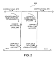
- FIG. 1 illustrates a block diagram of an example fluid regulatory testing system 100.
- the fluid regulatory testing system 100 includes a field test initiator 110 coupled to a fluid regulator control system 120 (e.g., valve positioning system, such as a system including a controller and a converter) that operates and/or controls a fluid regulator 130 (e.g., a valve, such as a ball valve, a globe valve, or any other type of fluid affecting device).
- a central control facility 140 may generate control signal 150 for fluid regulator control system 120.
- Central control facility 140 e.g., a control office remotely located from the fluid regulator
- control signal 150 is conveyed to field test initiator 110 from the central control facility 140.
- Field test initiator 110 receives control signal 150 and may alter the control signal prior to conveying the control signal to the fluid regulator control system 120.
- field test initiator 110 may include three user-input devices 111, such as field push-pull buttons, keypads, or rotary switches.
- User-input device 111 may be activated in the field by, for example, an operator depressing a button or turning a knob. Activation of user-input device 111 may activate a portion of the control signal modifier 112 of the field test initiator 110.
- Control signal modifier 112 may modify control signal 150 when a user-input device 111 is activated. For example, activation of one of the user-input devices 111 may direct control signal 150 to control signal modifier 112, where the control signal is altered by a predetermined amount (e.g., between approximately 2 mA and 4 mA or between approximately 3 mA and approximately 5 mA). As another example, activation of another user-input device 111 may activate a portion of control signal modifier 112 where the control signal is altered to a predetermined amount (e.g., 0 mA or 4 mA). In, for example, a current loop (e.g., 4-20 mA), the control signal modifier 112 may reduce the current of the control signal.
- a predetermined amount e.g., between approximately 2 mA and 4 mA or between approximately 3 mA and approximately 5 mA.
- activation of another user-input device 111 may activate a portion of control signal modifier 112 where the control signal is altered to
- the control signal 150 (e.g., altered control signal or unaltered control signal) may be conveyed to the fluid regulator control system 120.
- Fluid regulator control system 120 may determine whether to initiate a fluid regulator testing sequence (e.g., a stroke test) based on the conveyed control signal 150 and generates a fluid regulator control signal 150 based on the conveyed control signal 150. For example, if the control signal 150 has been altered, fluid regulator control system may generate a fluid regulator control signal to initiate a fluid regulator testing sequence or to adjust a position of a fluid regulator 130 to a safe mode position, as appropriate. As another example, if the control signal 150 has not been altered by field test initiator 110, the fluid regulator control signal may continue operations based on the control signal.
- a fluid regulator testing sequence e.g., a stroke test
- Initiating testing in the field may allow operators visually inspecting the fluid regulator control system and/or the fluid regulator and initiate testing without returning to a central control center. Additionally, allowing emergency shut-down in the field may allow operators in the field who observe abnormalities in operation, dangerous conditions, or the like to initiate shut-down (e.g., venting of fluids, restricting fluid flow, etc.) more quickly. Thus, safety may be increased since, for example, decreasing the amount of time in which a process is out of control during an emergency shut down decreases costs due to the production of undesirable products and/or reduces damage caused by out of control processes.
- control signal modifier may include combinations of electrical components, such as resistors, capacitors, diodes, shunts, etc.
- a control signal modifier may include one or more shunts.
- the control signal may be altered by the shunt when it meets operational criteria (e.g., above or below a predetermined range).
- control signal modifier 112 may be a passive device (e.g., a device that has zero or an insignificant amplification or power gain within the device). Utilizing a passive control signal modifier in the field test initiator may allow the control signal modifier to be operable without an additional power source (e.g., the field test initiator may operate on the power from the control signal).
- Additional power source e.g., the field test initiator may operate on the power from the control signal.
- FIG. 2 illustrates an electrical schematic of an example field test initiator 200 for use in a communication circuit (e.g ., a two-wire loop).
- the field test initiator 200 alters a control signal 210 by regulating current flow.
- Field test initiator 200 includes user-input devices 220, 240 to initiate a test and initiate an energy shut down, for example.
- field test initiator 200 may include a first user-input device 220 in electrical communication with a first diode 230 (e.g., 1N5283 diode). Activation of first user-input device 220 may cause a predetermined amount of control signal 210 to be bled to the ground line.
- a first diode 230 e.g., 1N5283 diode
- control signal is conveyed from field test initiator 200 as an altered control signal 215 that has a value less than control signal 210.
- Field test initiator 200 also includes a second user-input device 240 in electrical communication with a second diode 250. Activation of second user-input device 240 may also cause a predetermined amount of control signal 210 to be bled to the ground line.
- control signal 215 is also conveyed from field test initiator as an altered control signal that has a lower value than control signal 210.
- first diode 230 may be an approximately 4 mA current regulating diode and second diode 250 may be an approximately 16 mA current regulating diode.
- a 20 mA control signal may be transmitted from the central control facility to the field test initiator 200 to hold a fluid regulator in an open position, for example.
- the control signal 210 is allowed to pass through the field test initiator without substantially inhibition.
- the control signal 215 leaving the field test initiator 200 may not be substantially altered (e.g., control signal 215 has substantially the same value as the control signal 210 entering the field test initiator and/or control signal 215 has a value within approximately 100 ⁇ A of the control signal entering the field test initiator).
- first diode 230 When first user-input device 220 is activated, the first diode 230 allows approximately 4 mA of control signal 210 to pass to the ground line, and thus the value of the current of the altered control signal 215 may be approximately 16 mA.
- the 16 mA current signal may indicate to a fluid regulator control system that a fluid regulator testing sequence (e.g., partial stroke test, full stroke test, etc.) should be performed.
- second user-input device 250 When second user-input device 250 is activated, the second diode 240 allows approximately 16 mA of control signal 210 to pass to the ground line, and thus the resulting altered control signal 215 may have a current of approximately 4 mA.
- the 4 mA current signal may indicate to a fluid regulator control system that the fluid regulator should be positioned in a safe mode position (e.g., to allow gasses to vent or to inhibit fluid flow).
- the field test initiator may include an additional switch and an additional diode that alters the control signal to a predetermined value that may indicate to the fluid regulator control system that a full stroke test or other fluid regulator testing sequence should be performed.
- a passive control signal modifier is described, an electrically active control signal modifier may be designed, and, for example, electrical components that increase the value of the control signal to or by a predetermined amount may be used.
- the illustrated user-input device is depicted as including an electrical switch that acts with the control signal modifier, the electrical switch may be a portion of the control signal modifier and the electrical switch may detect activation of the user-input device and activate accordingly.
- FIG. 3 illustrates an electrical schematic of another example field test initiator 300.
- the field test initiator 300 may alter a control signal 310 based on the value of the control signal received.
- field test initiator 300 includes a first switch 320, a second switch 330, and a combination of resistors, diodes, capacitors, and op-amps (operational amplifiers).
- First switch 320 and second switch 330 may be coupled to user-input devices, such that when a user-input device is activated, the first and/or second switch is closed. Activation of first switch 320 or second switch 330 affects the control signal 310 in field test initiator 300.
- a portion of the control signal 310 enters a diode 340 (e.g., zener gap diode) that allows a fixed voltage signal to pass through.
- the fixed voltage signal passes through resistors and into the negative leg of the op-amp 350.
- the other portion of the control signal 310 passes through resistors prior to entering the positive leg of the op-amp 350.
- the signals in the positive and negative legs are compared. If the signal in the negative leg has a greater voltage than the signal in the positive leg, then current from the positive leg is drained (e.g., down to the negative leg, see path 360, by sinking current to the ground, etc.) until the voltages are approximately equal.
- the circuit may be designed so that the voltages in the positive and negative legs are approximately equal, the control signal 315 conveyed from the field test initiator 300 is approximately the same as the received control signal 310.
- the field test initiator alters the control signal. As illustrated, a portion of the control signal passes through another resistor prior to entering the negative leg of the op-amp.
- the field test initiator may be designed such that, when a 20 mA control signal is received and the first switch is activated, the resulting voltage of the signal in the negative-leg is greater than the voltage of the signal in the positive leg.
- the op-amp 350 then bleeds current from the positive leg to the ground until the voltage difference between the positive and negative legs is insignificant.
- the feedback leg from the op-amp passes though a capacitor and additional resistor to reduce noise (e.g., inhibit oscillation with the incoming current from the process controller).
- the field test initiator alters the control signal.
- a portion of the control signal 310 passes through an additional resistor prior to entering the negative leg of the op-amp 350.
- the additional resistor that the control signal passes through when the second switch 350 is activated may be different from the additional resistor that the control signal passes through when the first switch 330 is activated. Using different resistors may result in different voltages at the negative leg of the op-amp, and thus, different altered control signals leaving the field test initiator.
- the voltage at the negative leg of op-amp 350 is compared to the voltage of the signal in the positive leg; and, if the voltage of signal in the negative leg is higher than the voltage of the signal in the positive leg, current from the signal in the positive leg is bled to the ground line until the voltages are approximately the same. Thus, the current for the control signal 315 conveyed from the field test initiator is less than the current for the control signal 310 received by the field test initiator.
- the field test initiator may be designed such that the resulting voltage entering the negative leg of the op-amp is greater than the voltage of the signal in the positive leg, and the op-amp 350 may bleed current from the signal in the positive leg until the voltage difference is insignificant.
- the resulting altered control may be 16 mA.
- the field test initiator may alter the control signal when a switch is activated by an amount related to the received control signal and/or a predetermined amount of control signal may be sent to the fluid regulator control system when a user-input device is activated.
- the field test initiator may not alter the control signal if it does not satisfy operational criteria (e.g., if the value of the control signal is less than a specified value). For example, if a control signal of 16 mA enters the field test initiator, as described above, the field test initiator may be designed such that the resulting voltage entering the negative leg of the op-amp is approximately the same as or greater than the voltage of the signal in the positive leg, and the control signal 315 conveyed from the field test initiator will be approximately the same as the received control signal 310.
- a field test initiator may not alter signals below a specified value to inhibit the fluid regulator control system from interpreting the altered signal as a signal to position a fluid regulator in a safe mode position rather than a signal to initiate a fluid regulator testing sequence, for example. Additionally, a field test initiator may not alter signals that do not meet operational criteria (e.g., below a specified value) to inhibit the fluid regulator control system from initiating a fluid regulator testing sequence while the fluid regulator is in a safe mode position and/or while testing (e.g., initiated by the central control facility) is in progress.
- operational criteria e.g., below a specified value
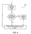
- FIG. 4 illustrates an example process 400 for fluid regulation field testing.
- Process 400 begins with receiving a control signal (operation 410).
- a control signal for a fluid regulator control system may be transmitted by a central control facility and received by the field test initiator.
- the control signal may be, for example, a current signal (e.g., 4 to 20 mA control loop), a voltage signal, and/or a frequency signal.
- the switches are described as a portion of the control signal modifier, the switches may be a portion of the user-input devices.
- Whether one or more user-input devices have been activated may be detected (operation 420).
- a user-input device may be coupled to an electrical switch or may include an electrical switch that activates a portion of the control signal modifier when activated.
- control signals may be conveyed to the fluid regulator control system (operation 430).
- the unaltered or insignificantly altered control signal may be conveyed by the field test initiator to a valve positioning system.
- control signal is altered (operation 440).
- the control signal may be altered by a portion of the field test initiator (e.g., a control signal modifier).
- the control signal may be altered by a predetermined amount (e.g., approximately 1 mA to approximately 5 mA, approximately 2 mA to approximately 4 mA, etc.) or may be altered to a predetermined amount (e.g., approximately 16 mA, approximately 4 mA, approximately 0 mA).
- the control signal may be altered by or to a predetermined amount for at least a predetermined period of time (e.g, approximately 2 seconds, approximately 3 seconds, etc.).
- a control signal may be altered for at least a predetermined period of time to distinguish the altered signal from fluctuations or other interruption in the control signal and/or to facilitate identification of the altered control signal by the controller. For example, a portion of the control signal may be diverted to the ground line when activation of a user-input device is detected.
- the control signal (e.g., altered or insignificantly altered control signal) is then conveyed to the fluid regulator control system (operation 430).
- control system After the control system is conveyed to the fluid regulator control system (operation 430), another control signal received may be processed (operation 410). For example, since control signals may be received by the field test initiator continuous or periodically (e.g., once every second, once every three seconds, etc.), the field test initiator may convey the received control signals to the fluid regulatory control system until activation of a user-input device has been detected.
- Process 400 may be implemented by system 100 or similar systems.
- various operations may be added, deleted, modified, or reordered in process 400.
- a value of a control signal may be determined.
- the alteration to the control signal, when a user-input device is activated may be based on the user-input device activated and/or the value of the control signal received.
- the control signal may not be altered when the control signal is below a predetermined value.
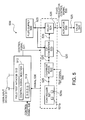
- FIG. 5 illustrates an example fluid regulatory testing system 500.
- Fluid regulatory testing system 500 includes a field test initiator 510 and a valve positioning system 520.
- a control signal 530 may be received by field test initiator 510 and conveyed to valve positioning system 520.
- the valve positioning system may generate a fluid regulatory control signal 535 to control a position of a valve 540.
- Field test initiator 510 includes user-input devices 511 that, when activated, activate a portion of a control signal modifier 512. Activation of a portion of control signal modifier may alter the control signal (e.g., reduce the voltage, reduce the current, increase the voltage, etc.). The alteration of the control signal 530 may indicate that a fluid regulator testing sequence should be performed or that a fluid regulator (e.g., valve 540) should be positioned in a safe mode position.
- a fluid regulator e.g., valve 540
- the control signal modifier 512 may alter control signal 530 via one or more electrical components.
- the control signal modifier may be a passive or an active electrical device.
- the control signal modifier may alter the received control signal 530 to indicate to valve positioning system 520 that a fluid regulatory testing sequence (e.g., partial stroke test) should be initiated and/or that a fluid regulator control signal should be generated to position a valve in a safe mode position.
- a fluid regulatory testing sequence e.g., partial stroke test
- the field test initiator 510 may also include indicators 513 (e.g., lights, LEDs, LCD screen, etc).
- the indicators 513 may provide information related to a fluid regulatory testing sequence.
- indicators 513 may indicate which fluid regulatory testing sequence is implemented by the valve positioning system (e.g., partial or full stroke test), if a user-input device was activated, whether the valve positioning system has initiated testing, whether the testing is in progress or complete, and/or the results of the fluid regulatory testing sequence (e.g., indication of valve health-poor, fair, good; where problems are identified in a valve positioning system, etc.).
- Field test initiator may receive signals 536 related to a fluid regulatory testing sequence via a wire coupling the field test initiator to the valve positioning system.
- the indicators 513 may be coupled to a power source (e.g., internal battery) that supplies power to the indicators.
- the field test initiator 510 may be coupled to the valve positioning system via a two-wire loop.
- a first two-wire loop coupler e.g., on the field test initiator
- a second two-wire loop coupler may receive the ground signal from the valve positioning system.
- Valve positioning system may receive control signal 531 from field test initiator 510 and send a fluid regulatory control signal 535 to an actuator 550, which adjusts a position of the valve 540 based on the fluid regulatory control signal 535.
- the valve positioning system 520 may include components such as a controller 521, an electric to pressure converter (E/P converter) 523, and a relay 524.
- Signal 535 may be transformed and modified by various components (e.g., E/P converter, relay, etc.) of the valve positioning system 520 and delivered to actuator 550 (e.g ., a piston subject to differential pressure) which operates on the valve 540.
- the controller 521 may include a programmable logic device 521a, such as a microprocessor, a microcontroller, a field programmable gate array (FPGA), a non-programmable logic device, such as an application specific integrated circuit (ASIC), or any other device for manipulating information in a logical manner. Additionally, controller 521 may include a memory 521b to store data and/or instructions. Memory 521b of controller 521 may include volatile or nonvolatile memory such as, RAM, ROM, optical memory, magnetic memory, flash memory, electrically-erasable, programmable ROM (EEPROM), phase-change RAM (PRAM), ferroelectric RAM (FeRAM), or any other appropriate device for storing information.
- EEPROM electrically-erasable, programmable ROM
- PRAM phase-change RAM
- FeRAM ferroelectric RAM
- Controller 521 may be operable in, for example, a current or voltage range (e.g., approximately 4 to approximately 20 mA, approximately 1 to approximately 24 volts, approximately 12 to approximately 24 volts, etc.).
- Controller 521 may receive control signal 531 and generate a signal to the E/P converter 523 based the received control signal. Controller 521 may determine whether to initiate a fluid regulatory testing sequence based on control signal 531. For example, controller 521 may determine whether the control signal 531 indicates that an operation is to be performed (e.g., initiate fluid regulatory testing sequence or generate fluid regulator control signals to position a fluid regulator in a safe mode position). The controller 521 may compare the received control signal to previous control signals to determined if the control signal has been adjusted. Controller 521 may detect (e.g., via electronic circuitry) whether the control signal has been adjusted. If the control signal has been adjusted, the controller may initiate a response. For example, the controller may initiate a fluid regulatory testing sequence or generating a fluid regulatory control signal that indicates that a position of a valve should be a safe mode position.
- Controller 521 may also detect a level of a control signal and initiate a response based on the control signal. For example, in a 4-20 mA current loop, the controller may initiate a fluid regulatory testing sequence when a control signal is a first predetermined amount, open a valve when a control signal is a second predetermined amount, and close a valve when the control signal is a third predetermined amount. Predetermined ranges (e.g., ⁇ 1 mA) may be used rather than predetermined amounts to indicate which action a controller should take.
- controller 521 may determine if received control signal 531 satisfies one or more operational criteria. For example, if the control signal satisfies a first operational criteria (e.g., below a specified value), the controller may generate a fluid regulatory control signal that indicates a valve should be adjusted to a safe mode position. If the control valve satisfies another operational criteria (e.g., in a specified range of values), a testing sequence may be initiated by the controller.
- a first operational criteria e.g., below a specified value
- the controller may generate a fluid regulatory control signal that indicates a valve should be adjusted to a safe mode position.
- another operational criteria e.g., in a specified range of values
- E/P converter 523 of valve positioning system 520 converts an electrical signal from controller 521 to a pressure signal of fluid or gas (e.g., air, natural gas, or other appropriate compressible gasses). Although an E/P converter is described, other appropriate converters capable of converting signals received from the controller may be used.
- Relay 524 may then amplify signals received (e.g., by pressure, volume, and/or flow rate) and convey the fluid regulatory control signal 535 to the actuator 550.
- Relay 524 may include, but is not limited to, a spring-diaphragm actuator, a spool valve, or a pneumatic amplifier.
- a fluid supply 560 e.g ., air or natural gas
- Valve positioning system may also include sensors 525 coupled to components and/or to connections between components.
- Sensors 525 may be any device capable of measuring a signal (e.g., electrical, mechanical, or fluid) or position produced and/or received by the valve positioning system.
- a sensor may measure parameters such as, but not limited to, pressure, flow rate, electrical current, electrical voltage, and/or a valve position.
- Sensors 525 may transmit data from monitored components to controller 521. Data from sensors 525 may be used to determine a health of a valve and/or identify problems with one or more components of the valve.
- Various analyses such as comparing input/output curves, F-test, Fourier transforms, etc., may be performed on the data from the sensors.
- trending analysis may be performed on the data from monitoring components.
- a problem with component(s) may be diagnosed based on the data. For example, data may be analyzed to determine if friction has increased in the valve or a leak exists in a connection between components of the fluid regulatory testing system.
- problems such as plugging in electrical to pressure output converters, deposits on electrical to pressure output converter flexures or nozzles, failure of controller electronics, performance shift of controller electronics, failure or leak in a relay (e.g., failure or leak in a diaphragm of a relay), gas leaks in tubing connections (e.g., to an actuator, a relay, or an electrical to pressure output converter), broken actuator springs, increased packing friction, low pressure gas stream delivery from gas supply, and/or temperature outside a predetermined range (e.g., high temperatures may cause failure in a few days)) may be diagnosed.
- a relay e.g., failure or leak in a diaphragm of a relay
- gas leaks in tubing connections e.g., to an actuator, a relay, or an electrical to pressure output converter
- broken actuator springs e.g., increased packing friction, low pressure gas stream delivery from gas supply, and/or temperature outside a predetermined range (e.g., high temperatures may cause failure in a few days
- valve positioning system 520 also includes an override device 522 (e.g., a safety override circuit or device).
- Override device 522 may provide safety control features to a fluid regulatory testing system. For example, if unsafe conditions exist in or affect the fluid regulatory testing system 500, override device 522 may modify or interrupt a signal provided to or by fluid regulatory testing system 520 to provide a signal that causes the fluid regulatory testing system to go to a "safe mode" (e.g ., vent fluids to atmosphere, close valves, or any action appropriate for a specific system).
- a safety mode e.g ., vent fluids to atmosphere, close valves, or any action appropriate for a specific system.
- the override device may interrupt the signal to the E/P converter 523 and cause the fluid regulatory testing system to go to a safe state (e.g ., closing a feed line to the process).
- a safe state e.g ., closing a feed line to the process.
- the override device may modify the signal to cause the fluid regulatory testing system to close a valve upstream of the leak.
- Override device 522 may be implemented using digital components, analog components, or a combination thereof. Override device 522 may be any collection of electronic components that can interrupt or modify the communication of a signal to E/P converter 523 without disrupting the ability of the signal to power controller 521 and/or sensors 525. Override device 522 may be located apart from controller 521, such as on a separate printed circuit board, or it may be integrated with the controller.
- a trip signal 537 and/or control signal 531 may control operation of override device 522.
- Trip signal 537 may be regulated by an external control mechanism, which may base determinations on data received from various parts of a regulation process and/or facility.
- Override device 522 may, for example, be triggered in response to receiving trip signal 537 (e.g ., for testing purposes or to cause a fluid regulatory testing system to go to a safe state), detecting a change in the state of control signal 531 (such as rapid changes in the control signal), detecting an interruption in the trip signal or the control signal, receiving notice of an unsafe condition, or any of numerous other events which require operating fluid regulatory testing system in a safe state.
- the modification performed on the signal transmitted from controller 521 to E/P converter 523 may be any suitable modification to cause the E/P converter to perform an action associated with the "safe mode" (e.g ., transitioning to a default state, such as closed, or freezing the current state).
- the "safe mode" e.g ., transitioning to a default state, such as closed, or freezing the current state.
- some E/P converters 523 vent to the atmosphere (e.g ., a valve is opened that releases fluids in the fluid regulatory testing system to the atmosphere) when the control signal is interrupted.
- the override device 522 When the override device 522 is triggered based on control signal 531 (e.g., when control signal 531 rapidly changes or fluctuates), the override device modifies the signal transmitted from controller 521 to E/P converter 523 such that the E/P converter generates a signal in response that corresponds to positioning the fluid regulator (e.g., valve 540) in a safe mode.
- the override device may modify the signal transmitted from the controller 521 to the E/P converter 523 so that a position of valve 540 is moved from closed to the safe mode position of "open" by actuator 550 in response to the fluid regulator control signal 535.
- Override device 522 which may be viewed as a safety override circuit in one aspect, may have a variety of configurations.
- override device 522 may receive control signal 531 before it is provided to controller 521.
- override device 522 may evaluate control signal 531 and determine whether to modify the signal to E/P converter 523 while still allowing controller 521 to extract power and communications from the control signal.
- Modifying the signal to the E/P converter 523 may include boosting, attenuating, transforming, interrupting, converting, or otherwise manipulating the signal to produce a particular response from E/P converter. If the command signal does not indicate that a condition is occurring, the control signal output by override device 522 may be essentially the same as one that enters.
- override device 522 may, for example, include a transistor coupled to the control signal line and controlled by a comparator.
- the transistor may be any suitable current- or voltage-controlled electronic component that restricts or allows current flow in response to a signal at a control terminal (discussed here as a comparator).
- the transistor may be p-type or n-type field effect transistor (FET), such as metal oxide semiconductor FET (MOSFET) that is controlled by a voltage applied to a gate terminal of the MOSFET.
- FET metal oxide semiconductor FET
- the comparator may be any circuitry for comparing a reference input signal to a threshold input signal (e.g., an op-amp) and producing an output to control the transistor in response to the comparison.
- override device 522 may receive an input current generated from the control signal.
- a resistor may be coupled to the negative line of the signal and placed in parallel with a diode to develop a voltage proportional to the signal's input current.
- a resistor may also be coupled to the positive line of the signal to produce a characteristic voltage drop representative of the signal's input current.
- a voltage regulator may work with the second resistor to form a constant reference voltage against which the voltage across the first resistor is compared.
- the comparator performs the comparison of the characteristic voltage representative of the input current to the reference voltage. If the characteristic voltage falls out of range (e.g., below the reference voltage), because the input current is too low or because the voltage regulator has shunted the input current to ground because it was too high, the comparator turns off its respective transistor, thus interrupting current flow to the E/P converter.
- the circuitry can be redundantly duplicated to provide added security.
- override device 522 may, for example, include a transistor in the positive path of the control signal.
- the transistor may be any suitable current- or voltage-controlled electronic component that restricts or allows current flow in response to a signal at a control terminal (discussed here as a voltage regulator).
- the voltage signal used to control the transistor is the trip signal, stepped down by a voltage regulator to a voltage level appropriate for the transistor.
- a 24-V trip signal could be stepped down for 5 V if the transistor was a 5-V MOSFET.
- the override device may also have a resistor coupled between the positive path of the signal and the gate line of the transistor to prevent current from the stepped-down trip signal from significantly altering the signal.
- the resistor may be selected to have a relatively high resistance value, such as 1 M ⁇ , to minimize current flow.
- the transistor In operation, the transistor allows current flow as long as the stepped-down voltage from the trip signal is maintained.
- trip signal 537 is interrupted, the current flow through the transistor is interrupted, thus interrupting the signal to the E/P converter.
- the E/P converter transitions to a safe state, such as venting to the atmosphere.
- the override device provides an effective operation for stopping the signal in response to the trip signal 537.
- the override device 522 may include two duplicate override circuits for increased reliability.
- the features of monitoring the control signal and monitoring trip signal 537 may be provided in one override device 522 (e.g., on the same circuit board). In application, however, it may be that only one of the safety features is used. Furthermore, although mention has been made of the override device having redundancy through duplicate circuits, it may be advantageous to provide redundancy through non-duplicate circuits, which may reduce the chance of both circuits being affected by the same condition. In certain implementations, however, redundancy is not required.
- control signals may be delivered to controller 521 over a wire loop (e.g., a wire pair). Utilizing one wire loop may simplify operations and/or reduce interference.
- Controller 521 which is powered by control signal 531, generates an appropriate signal to send to E/P converter 523 based at least partially on the control signal.
- the signal is then provided to override device 522, which conveys the signal to E/P converter 523.
- E/P converter 523 converts the electric signal to a pressure signal (e.g., fluid regulatory control signal 535) for delivery to relay 525, which may modify or maintain the pressure signal.
- the pressure signal is then transmitted to actuator 550, which adjusts the position of valve 540 based on the pressure signal.
- control signal 531 is sent to override device 522 of valve positioning system 520.
- Override device 522 determines whether the signal to E/P converter 523 should be modified or interrupted (e.g., due to conditions that require the fluid regulatory testing system to go to a safe state). If override device 522 determines that the signal does not need to be modified or interrupted, the signal is conveyed to E/P converter 523.
- override device 522 determines that the signal should be interrupted, the signal to E/P converter 523 is terminated while power is maintained to controller 521 (e.g., by allowing control signal 531 to pass to controller 521). Termination of the signal to the E/P converter allows the fluid regulatory testing system to go to a safe mode position (e.g ., close valve 540). Since power is maintained to controller 521, and/or sensors 525, if required, components of the fluid regulatory testing system may be monitored.
- a safe mode position e.g ., close valve 540
- Override device 522 may modify or interrupt the signal to the E/P converter 523 for a variety of reasons, such as the detection of an unsafe condition in or affecting the fluid regulatory testing system. For example, if values measured by sensors 525 exceed a safe range, controller 521 may transmit a message to override device 522 indicating the unsafe conditions. As another example, if an unsafe condition is detected (e.g ., out of range signals, position, temperature, reference voltage, and/or pressure values; memory faults; degradation of E/P converter; and/or degradation of relay responsiveness during one or more checks), override device 522 may interrupt the control signals output by the controller.
- an unsafe condition e.g ., out of range signals, position, temperature, reference voltage, and/or pressure values; memory faults; degradation of E/P converter; and/or degradation of relay responsiveness during one or more checks
- override device 522 may interrupt the control signals output by the controller.
- Controller 521 may include a HART modem to receive messages, such as commands, communicated in the control signal 531 or other signals between components of the fluid regulatory testing system.
- the HART modem allows sensors, transducers, controllers, and other devices to communicate in a network over a signal range, such as a 4-20 mA current loop connection.
- the HART modem may modulate the signal (e.g ., create a 1200 baud FSK signal) in the loop that enables communication with the controller 521.
- the HART modem may transmit commands to controller 521, which may store the commands in memory such as RAM, EEPROM, or flash memory.
- the field test initiator and the valve positioning system may be at least partially disposed in separate or the same housing.
- the housing(s) may at least partially enclose the field test initiator and/or at least one of the components of the valve positioning system.
- Using a field test initiator in a separate housing than the valve positioning system may allow operators to access the field test initiator without opening the housing of the valve positioning system and/or may allow operators to install the field test initiator on existing valve positioning systems without opening the housing to the valve positioning system.
- the housing(s) may be weather resistant, explosion resistant and/or proof, and/or meet government and/or industry standards. Positioning the field test initiator, controller, override device, and/or other components in housing(s) may facilitate installation of the fluid regulatory testing system and/or prevent damage to components and/or controllers.
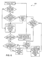
- FIG. 6 illustrates an example of a process 600 for fluid regulation.
- Process 600 may be an example of an operation performed by the system of FIG. 5 .
- Process 600 begins by receiving a control signal (operation 610).
- a control signal may be transmitted to and received by a field test initiator.
- the control signal may be, for example, a current or a voltage signal.
- the determination may be made by the field test initiator via electrical components or via, for example, a microprocessor or PLD.
- the field test initiator may include a comparator, such as an op-amp.
- the op-amp as previously described, may not alter the control signal if it does not satisfy operational criteria (e.g., within a predetermined range).
- operational criteria may indicate, for a 4-20 mA control loop, that when control signal between approximately 2 mA and 5 mA is received, the control signal should not be altered. Inhibiting alteration of a control signal below a predetermined amount or in a predetermined range may inhibit testing while a fluid regulator is in a safe mode position. As another example, operational criteria may indicate, for a 4-20 mA control loop, that when a control signal between approximately 14 mA and approximately 18 mA is received, the control signal should not be altered.
- Inhibiting alteration of a control signal in a predetermined range may inhibit the field test initiator from altering the control signal to initiate testing when the central control facility has already initiated testing and/or may inhibit unintentional alteration of the control signal into signal associated with a safe mode position, when testing is requested.
- control signal may be altered (operation 640).
- a control signal modifier may alter the control signal by a predetermined amount (e.g., 2-4 mA) or alter the control signal to a predetermined amount (e.g., 16 mA, 4 mA, etc.).
- the control signal may be altered based on which electrical path the user-input device activates in the control signal modifier.
- an electrical path in the control signal modifier that alters the control signal to a signal associated with positioning the fluid regulator in a safe mode (e.g., 0 mA, 4 mA, 20 mA) may be activated.
- an electrical path in the control signal modifier may be activated to reduce the control signal to predetermined amount (e.g., 8 mA, 14 mA, 16 mA, 18 mA, etc.) that indicates to the controller of the fluid regulator control system that a fluid regulator testing sequence should be initiated.
- the control signal may then be conveyed to the fluid regulator control system (operation 650).
- the control signal may be conveyed to a controller and/or an override device of the fluid regulator control system.
- the fluid regulator control system may include electrical components to detect whether the control signal has been altered and/or a controller of the fluid regulator control system may detect whether the control signal has been altered. If the control signal has not been altered, a position of the fluid regulator may be adjusted (e.g., to a safe mode position) based on the control signal, if required (operation 670).
- control signal may be compared to operational criteria (e.g., whether the control signal is above or below a predetermined amount) to determine whether to initiate testing.
- operational criteria e.g., whether the control signal is above or below a predetermined amount
- control signal may be compared to operational criteria (e.g., whether the control signal is above or below a predetermined amount) to determine whether to initiate testing.
- operational criteria e.g., whether the control signal is above or below a predetermined amount
- Determining whether to initiate a fluid regulator testing sequence may be based on the position of the fluid regulator. For example, if the fluid regulator is in a safe mode position, testing may be inhibited. Testing may be inhibited while a fluid regulator is in a safe mode in order maintain the safe mode operation of the fluid regulatory testing system. As another example, if the fluid regulator is in a closed position, testing may be inhibited. Testing may be inhibited while a fluid regulator is closed to inhibit fowling of the process and/or to maintain current operations.
- a fluid regulator testing sequence may be initiated (operation 685).
- a fluid regulator testing sequence may include adjusting the position of a fluid regulator (e.g., by generating fluid regulator control signals sent to an actuator), monitoring components of the fluid regulator control system and/or the fluid regulator, and/or determining fluid regulator health and/or health of components of the fluid regulatory testing system. Sensors in the fluid regulator control system and the fluid regulator may provide data while monitoring the fluid regulatory testing system.
- a signal related to the fluid regulator testing sequence may be sent to the field test initiator (operation 690), and the illumination of the indicators on the field test indicator may be altered based on the received signal related to testing (operation 695). For example, LEDs on the field test initiator may be turned on or off or a color of a light may be changed based on the received signals. The illumination of the indicators may provide information about the fluid regulator testing sequence.
- signals e.g., related to the progress and/or results of testing
- Process 600 may be implemented by system 500 or similar systems.
- various operations may be added, deleted, modified, or reordered in process 600.
- whether the control signal satisfies operational criteria may not be determined (e.g., by the field test initiator and/or the fluid regulator control system), and the control signal may be altered when at least one of the user-input devices is activated.
- the field test initiator may alter a control signal when at least one of the user-input devices is activated and the fluid regulator control system may determine whether the altered control signal satisfies operational criteria prior to initiating testing.
- a determination whether the control signal has been altered may not be made and a determination of whether to initiate a fluid regulator testing sequence may be based on the control signal received.
- an indicator may be auditory and a sound may increase, commence, or end.
- a visual indicator may display a new or altered image rather than an illumination of the indicator changing.
- control signal may be continuously received
- the process may be interrupted by a later received control signal. For example, if an emergency shut down signal is received, testing may be terminated.
- a fluid regulator testing sequence may be interrupted when the control signal fails to satisfy operational criteria (e.g., when the value of the control signal is outside the range that indicates a testing sequence should be performed, the testing sequence may be interrupted).
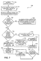
- FIG. 7 illustrates another example of a process 700 for fluid regulation.
- Process 700 begins with receiving a control signal (operation 705).
- the control signal may be altered if a user-input device has been activated (operation 710).
- the control signal may be received by the field test initiator and altered by a control signal modifier of the field test initiator, if a user-input device is activated.
- the control signal may be conveyed to the valve positioning system (operation 715).
- the control signal may be transmitted to the valve positioning system via a wire of a two-wire loop.
- First operational criteria may include whether the control signal is greater than a predetermined value. If the control signal does not satisfy the first operational criteria, a fluid regulatory control signal may be generated to adjust a valve position to a safe mode position (operation 725). For example, a safe mode position may vent gasses or inhibit fluid flow, based on the application in which the valve is used.
- the valve and/or components of the valve positioning system may be monitored and/or a health of the valve may be determined. The illumination of indicators on the field test initiator may be altered based on the determined health of the valve.
- a valve may be maintained in a safe mode position until a control signal indicating that a position of a valve should be adjusted is received.
- the second operational criteria may include a predetermined range of values (e.g., 15-17 mA).
- scond operational criteria may include whether the control signal is within a predetermined range for at least a predetermined period of time and/or whether the control signal has been altered for at least a predetermined period of time.
- control signal does not satisfy the second operational criteria, the previous operations may continue without substantial interruption (operation 735).
- One feature of the field test initiator may be to inhibit initiating a fluid regulatory testing sequence when a control signal is lower than a predetermined amount, so that testing is not initiated when a valve should be in a safe mode.
- second operational criteria may include that if a fluid regulatory testing sequence has been initiated, a new fluid regulatory testing sequence may not be initiated while the previous testing is in progress.
- a fluid regulatory testing sequence may be initiated (operation 740). For example, if a control signal is in a predetermined range (e.g., between approximately 15 and approximately 17 mA) and lasts for a predetermined time period (e.g., between approximately 2 and approximately 5 seconds), then a second operational criteria may be satisfied. Operational criteria may include a length of time a predetermined control signal is maintained to prevent minute fluctuations or interruptions from triggering testing or adjusting a valve position to a safe mode position.
- a fluid regulatory testing sequence may include any testing of a valve to facilitate determination of a valve health and/or identification of problems in a valve and/or valve positioning system.
- a fluid regulatory control signal may be generated to alter a position of a valve (operation 745). For example, a valve position may be adjusted by a predetermined amount (e.g., from 100% to 80% open, etc.).
- Components of the valve positioning system and/or the valve may be monitored (operation 750). For example, sensors in the valve positioning system may transmit data to the controller. Valve positioning system and/or valve health may be determined (operation 755).
- a controller may analyze the data received from sensors and determine a valve health and/or identify problems in the valve or valve positioning system.
- Signals may be transmitted to the field test initiator related to the testing (operation 760) and the illumination of the indicators may be altered based on the received signals (operation 765). For example, an orange LED on the field test initiator may be illuminated when the fluid regulatory testing sequences is initiated. A green LED may indicate that the valve health is good. Illumination of none of the LEDs on the field test initiator may indicate that none of the user-input devices have been activated, and illumination of all the LEDs may indicate an emergency shut down was initiated by the field test initiator. Although LED indicators are described, any appropriate auditory or visual indicator may be used. Use of indicators may provide feedback to operators in the field of the progress and/or results of fluid regulatory testing sequences.
- Process 700 may be implemented by system 500 or similar systems.
- various operations may be added, deleted, modified, or reordered in process 700.
- the control signal may be evaluated by more than two or less than two operational criteria.
- signals related to testing may not be transmitted to the field test initiator. Signals related to testing may be transmitted to the central control facility.
- system and processes for fluid regulation may include a latch mode to maintain an operation of the system.
- a fluid regulator control system in a latch mode may inhibit generation of fluid regulator control signals based on received control signals and/or inhibit alteration of a position of a fluid regulator.
- Safety of operations may be increased by latching a fluid regulator control system.
- a position e.g., predetermined position, safe mode position, open, closed, partially open, etc.
- unlatching the fluid regulator control system may require operators to be in the proximity of the fluid regulator control system and/or the fluid regulator to determine whether it is safe to restart the process and therefore, initialize the fluid regulating device (e.g., fluid regulator control system is not longer in a latch mode).
- Latching a fluid regulator in a safe mode may inhibit accidental interruption of a safe mode and/or interruption of a safe mode due to control signal interruptions and/or fluctuations.
- latching a fluid regulator in a safe mode may inhibit an operator in a central control facility from resuming operations of a valve without observing the valve from the field and/or while other operators are observing the valve in the safe mode.
- maintaining a position, such as open or closed, such as by commencing a latch mode for a valve positioning system may increase worker safety during shut down and/or maintenance operations.
- FIG. 8 illustrates an example of a system 800 for fluid regulation.
- System 800 includes a field test initiator 810 coupled to a fluid regulator control system 820 (e.g., a valve positioning system).
- Control signals 830 may be conveyed from a central control facility 840 to the fluid regulatory control system 820 via a communication circuit (e.g., a two-wire loop, a four-wire loop, etc.) that includes field test initiator 810.
- a communication circuit e.g., a two-wire loop, a four-wire loop, etc.
- Fluid regulator control system 820 may include a controller 821 and a E/P converter 822.
- Control signals 840 received by the fluid regulator control system may be conveyed to the controller 821 (e.g., directly from the field test initiator 810 or central control facility 840 and/or indirectly from an override device).
- Controller 821 may generate fluid regulator control signals based on the received control signals 840.
- controller 821 sends signals generated based on control signal 840 to E/P converter 822.
- E/P converter 822 may convert the electrical signal received from the controller to a pneumatic signal.
- the pneumatic signal from the E/P converter may be sent (e.g., directly or indirectly though one or more relays) to actuator 860, which operates on a fluid regulator 870 (e.g., safety valves, relief valve, ball valves, etc.).
- a fluid regulator 870 e.g., safety valves, relief valve, ball valves, etc.
- Fluid regulator control system 820 may have a latch mode.
- a latch mode may be associated with and/or maintain a position (e.g., predetermined position, previous position, and/or safe mode position) of a fluid regulator. While the fluid regulator control system is in a latch mode, generation of fluid regulator control signals may be inhibited and/or a fluid regulator position may be maintained. For example, controller 821 may not transmit signals to E/P converter 822. As another example, controller 821 may generate fluid regulator control signals as previously generated rather than adjusting the fluid regulator control signals based on the received control signals during latch mode.
- a latch mode may be commenced by controller 821.
- a signal (e.g., electric) may indicate to controller 821 that a latch mode should be commenced. For example, when a control signal is received that indicates a fluid regulator control signal should be generated to position a fluid regulator in a safe mode position and/or when a fluid regulator position is detected as a safe mode position, controller 821 may commence a latch mode.
- a latch mode may be commenced when a trip signal is received by field regulator control system 820.
- a trip signal may be received by controller 821, and the controller may commence a latch mode in response.
- the trip signal may be transmitted to field regulator control system 820, for example, via a communication circuit loop of the control signal 830, 840 and/or the wire loop on which the unlatch signal 880 is conveyed.
- a trip signal may be received by a HART modem of controller 821.
- Controller 821 may include a software switch that inhibits generation of fluid regulator control signals until an unlatch signal 880 is detected.
- Unlatch signals 880 may include interrupts (e.g., voltage interrupts) and/or a short circuit.
- the latch mode is removed (e.g., the field regulator control system is no longer in a latch mode).
- Unlatch signal 880 may be generated by a user-input device 811 (e.g., field button, switch, etc.) of the field test initiator 810. For example, activation of a user-input device 811 1 coupled to fluid regulator control system 820 may cause an unlatch signal 880 to be conveyed to the controller 820. Unlatch signal 880 may be conveyed to controller 821 via a different wire loop than the wire loop in which the control signal 830, 840 is conveyed. For example, a 4-20 mA control signal 840 may be conveyed via a two-wire loop to the fluid regulator control system 820 while the unlatch signal 880 may be conveyed to controller 821 of the fluid regulatory system via a separate two-wire loop.
- a user-input device 811 e.g., field button, switch, etc.
- Unlatch signal 880 may be conveyed to controller 821 via a different wire loop than the wire loop in which the control signal 830, 840 is conveye
- a controller may receive the 4-20 mA control signal via a first wire loop.
- the controller receives control signal and applies a voltage differential at terminations of a second wire loop (e.g., on a printed circuit board of the controller).
- Unlatch signal 880 is conveyed on the second wire loop, which may be short circuited (e.g., by activation of a user-input device), to generate unlatch signal 880.
- Field test initiator 810 may be similar to the previously described field test initiators in system 100, 500 and/or field test initiators 200, 300. Field test initiator 810 may perform one or more of the processes previously described, such as processes 400, 600, 700. As illustrated, field test initiator 810 may include one or more other user-input devices 811. Activation of one of the other user-input devices may alter the control signal (e.g., by or to a predetermined amount), for example, by activating a portion of a control signal modifier 812. For example, activation of one of the other user-input devices 811 may alter a control signal to indicate to controller 821 that a fluid regulator testing sequence (e.g., partial or full stroke test) should be performed.
- a fluid regulator testing sequence e.g., partial or full stroke test
- activation of one of the other user-input devices 811 may indicate to controller 821 that a fluid regulator 870 should be positioned in a predetermined position, such as a safe mode position (e.g., by generating fluid regulator control signals to position the fluid regulator in the predetermined position; by terminating the generation of fluid regulator control signals, where a fluid regulator is positioned in a predetermined position when no fluid regulator control signals are generated; etc.).
- a fluid regulator 870 positioned in a predetermined position, such as a safe mode position (e.g., by generating fluid regulator control signals to position the fluid regulator in the predetermined position; by terminating the generation of fluid regulator control signals, where a fluid regulator is positioned in a predetermined position when no fluid regulator control signals are generated; etc.).
- field test initiator 810 is illustrated as in a communication circuit, the field test initiator may be separately coupled to fluid regulator control system 820.
- the field test initiator 810 may not be in the communication circuit between central control facility 840 and a valve positioning system.
- the field test initiator 810 may, for example, be coupled to a valve positioning system via a separate wire loop (e.g., a one wire loop, a two wire loop, a four wire loop, etc) from the wire loop to and from central control facility 840.
- field test initiator 810 may not include a user-input device that when activated, alters a control signal to indicate to a fluid regulator control system that a fluid regulator testing sequence should be commenced.
- user-input device 811 is illustrated as disposed on field test initiator 810, the user-input device may not be coupled to the field test initiator.
- user-input device 811 may be coupled to fluid regulator control system 820 (e.g., disposed on a housing of a valve positioning system and/or coupled to controller 821).
- FIG. 9 illustrates a process 900 for fluid regulation by systems, such as systems 100, 500, 800 illustrated in FIG. 8 .
- Process 900 begins with receiving a control signal (operation 910).
- a control signal may be received from a field test initiator and/or a central control facility The control signal may have been altered by the field test initiator, such as when user-input devices are activated.
- a control signal may include a trip signal received by the fluid regulator control system. The trip signal may be transmitted (e.g., via control signal wire loop or unlatch signal wire loop) to a controller.
- a control signal that has been altered e.g., by the central control facility and/or field test initiator
- a control signal with a predetermined value e.g., 0 mA, 4 mA, or 20 mA
- a fluid regulator control signal may be generated to adjust a position of a fluid regulator to a safe mode position (operation 930). For example, no signal may be generated when a termination of a fluid regulator control signal adjusts a fluid regulator to a safe mode position. As another example, a predetermined control signal may be generated. If the fluid regulator is in a safe mode position, then the safe mode position may be maintained.
- the fluid regulator control system may commence a latch mode (operation 940).
- a controller of a fluid regulator control system may restrict operations in a latch mode (e.g., generation of fluid regulator control signals and/or initiating of fluid regulator testing sequences may be restricted or disallowed; fluid regulator control signals may be generated based on a previous fluid regulator position, a predetermined position, and/or a safe mode position, rather than received control signals; etc.).
- Generation of fluid regulator control signals based on the received control signals may be inhibited (operation 950).
- alteration of the fluid regulator position e.g., a safe mode or predetermined position
- fluid regulator control signals may not be transmitted to a override device and/or an E/P converter.
- the controller of the fluid regulator control system may continue to inhibit generation of fluid regulator control signals based on received control signals, as new control signals are received (operation 910), until an unlatch signal is detected.
- the latch mode may be determined by the controller.
- an unlatch signal may be conveyed when a user-input device is activated.
- the unlatch signal may include short circuiting a wire loop coupled to the controller and/or an interrupt (e.g., voltage interrupt). If the unlatch signal has not been detected, generation of fluid regulator control signals based on the control signals may be inhibited (operation 950).
- a fluid regulator control signal based on the received control signal may be generated (operation 980).
- the controller may generate fluid regulator control signals based on the control signals to alter a fluid regulator position once the unlatch signal has been detected and/or when the fluid regulator control system is not in a latch mode.
- Process 900 may be implemented by system 100, 800, or similar systems.
- various operations may be added, deleted, modified, or reordered in process 900.
- a fluid regulator position may be maintained (e.g., at a previous position or safe mode position) in latch mode.
- a latch mode may correspond to a predetermined position (e.g., open, closed, or partially open).
- a determination of whether a received control signal indicates a fluid regulator should be in the predetermined position may be made; and while the fluid regulator control system is in a latch mode, the predetermined position may be maintained.
- a user-input device may be activated to alter a control signal to be received by the fluid regulator control system and the altered signal may indicate that a fluid regulator control signal should be generated that is associated with positioning a fluid regulator in a safe mode position.
- the controller may generate the fluid regulator control signal associated with positioning a fluid regulator in a safe mode position, in response, commence a latch mode, and maintain the latch mode until an unlatch signal is detected.
- a fluid regulatory testing system or valve may be used in safety-implemented systems (e.g., relief valves, rupture disks, and other systems with high reliability standards).
- the use of fluid regulator control systems (e.g., emergency shut down valves) in safety-implemented systems that are capable of diagnosing problems and/or failures prior to the problem or failure occurring may meet and facilitate compliance with regulations of safety implemented systems (e.g., government, industry, and/or business safety standards). Since emergency shutdown valves are not used in day-to-day operations, testing (e.g., partial stroke testing) is performed periodically (e.g., once a month) to ensure operation and/or reduce the risk of failure of the system.
- valves may stick after prolonged periods of inactivity.
- a fluid regulator testing sequence such as a full stroke test or partial stroke test, may be performed on the fluid regulator to ensure operation and/or reduce the risk of failure.
- the fluid regulator and/or components of a fluid regulatory testing system may be monitored during the fluid regulator testing sequence.
- using a predetermined signal that corresponds to a signal to position a fluid regulator in a safe mode e.g., open or closed depending on the application in which the fluid regulator is used
- some power to be provided to the controller e.g., 4 mA rather than 0 mA in a 4-20 mA control signal loop
- Monitoring the components while testing may provide an indication of the operation and/or the health of the fluid regulatory testing system (e.g., fluid regulator, actuator, and/or fluid regulator control system) during the full open/close operation of a fluid regulator.
- monitoring components while closing the fluid regulator may facilitate identification of problems or potential problems with components (e.g., excess friction in valve stem, debris in the actuator, leaks in couplings or lines, etc.). Identification of problems and potential problems may decrease down-time of operations and improve safety.
- the field test initiator described here may have a display device (e.g ., indicators, LCD (liquid crystal display) panel, etc.) for displaying information to the user and, a keyboard by which the user can provide input to the field test initiator.
- the user may provide input to the field test initiator using other types of user-input devices, such as touch screens, mice, pointing devices, a stylus, keypads, buttons, switches, etc and/or input from the user may be received in any form, including acoustic, speech, or tactile input.
- Other kinds of devices can be used to interact with a user as well.
- feedback provided to the user by an output device may be any form of sensory feedback (e.g ., visual feedback, auditory feedback, and/or tactile feedback).
Claims (17)
- System zur Flüssigkeitsregulierung, das System umfassend:einen Feldtestinitiator (110; 200; 300; 510; 810), angepasst zum:Empfangen eines Steuersignals (150; 210; 310; 530; 830) für ein Flüssigkeitsregulatorsteuersystem (120; 520; 820);Leiten des Steuersignals (150; 215; 315; 531; 840) zum Flüssigkeitsregulatorsteuersystem (120; 520; 820); undVerändern des Steuersignals (150; 215; 315; 531; 840), das zu dem Flüssigkeitsregulatorsteuersystem (120; 520; 820) geleitet wird, beim Erfassen von Aktivierung mindestens eines Benutzer-Eingabegerätes (111; 220; 240; 511; 811) des Feldtestinitiators (110; 200; 300; 510; 810); und wobeidas Flüssigkeitsregulatorsteuersystem (120; 520; 820) an den Feldtestinitiator (110; 200; 300; 510; 810) gekoppelt ist, wobei das Flüssigkeitsregulatorsteuersystem angepasst ist zum:Empfangen des Steuersignals (150; 215, 315; 531; 840) von dem Feldtestinitiator (110; 200; 300; 510; 810);Generieren von Flüssigkeitsregulatorsteuersignalen (535), basierend auf dem empfangenen Steuersignal (150; 215; 315; 531; 840); undBestimmen, ob eine Flüssigkeitsregulatortestsequenz, basierend auf dem Steuersignal (150; 215; 315; 531; 840) initiiert werden soll.
- System nach Anspruch 1, wobei das Steuersignal (150; 210; 310; 530; 830) ein Stromsignal umfasst, optional wobei der Feldtestinitiator (110; 200; 300; 510; 810) angepasst ist, das Steuersignal (150; 215; 315; 531; 840), das zum Flüssigkeitsregulatorsteuersystem zugeführt wird, um zwischen ungefähr 2 mA und ungefähr 4 mA zu verändern, beim Erfassen der Aktivierung mindestens eines der Benutzer-Eingabegeräte (111; 220; 240; 511; 811) des Feldtestinitiators.
- System nach Anspruch 1, wobei der Feldtestinitiator (110; 200; 300; 510; 810) mindestens ein Benutzer-Eingabegerät (111; 220; 240; 511; 811) umfasst, das angepasst ist, sodass Aktivierung des mindestens einen Benutzer-Eingabegerätes einen Teil eines Steuersignalmodifikators (112; 512; 812) aktiviert, und wobei der Steuersignalmodifikator (112; 512; 812) angepasst ist zum:Verändern des Steuersignals (150; 215; 315; 531; 840) um einen vorbestimmten Betrag; oderVerändern des Steuersignals (150; 215; 315; 531; 840) auf ein vorbestimmtes Signal, wobei das vorbestimmte Signal mit einem Signal zur Positionierung eines Flüssigkeitsregulators (130; 870) in einer sicheren Betriebsposition übereinstimmt.
- System nach Anspruch 1, wobei das Flüssigkeitsregulatorsteuersystem (120; 520; 820) einen Controller beinhaltet, angepasst, um einen Teilhubtest zu initiieren, wenn das Steuersignal verändert worden ist.
- Verfahren zur Flüssigkeitsregulierung, das Verfahren umfassend:Empfangen (410; 610; 705) eines Steuersignals für ein Flüssigkeitsregulatorsteuersystem an einem Feldtestinitiator;Leiten (430; 650; 715) des Steuersignals vom Feldtestinitiator zum Flüssigkeitsregulatorsteuersystem;Verändern (440; 640; 710) des Steuersignals durch den Feldtestinitiator beim Erfassen (420; 620) von Aktivierung mindestens eines Benutzer-Eingabegerätes des Feldtestinitiators;Empfangen des Steuersignals vom Feldtestinitiator am Flüssigkeitsregulatorsteuersystem, wobei das Flüssigkeitsregulatorsteuersystem angepasst ist, um Flüssigkeitsregulatorsteuersignale zu generieren, basierend auf dem Steuersignal; undam Flüssigkeitsregulatorsteuersystem, Bestimmen (680; 720; 730), ob eine Flüssigkeitsregulatortestsequenz (685; 740), basierend auf dem Steuersignal, initiiert werden soll.
- Verfahren nach Anspruch 5, wobei Initiieren der Flüssigkeitsregulatortestsequenz (685) umfasst:Erfassen (660), ob das Steuersignal verändert worden ist; undInitiieren (685) eines Teilhubtests eines Flüssigkeitsregulators, wenn das Steuersignal verändert worden ist; oder wobei Initiieren der Flüssigkeitsregulatortestsequenz (740) umfasst:Verändern (745) einer Position eines Flüssigkeitsregulators, gekoppelt an das Flüssigkeitsregulatorsteuersystem;Überwachen (750) einer oder mehrerer der Komponenten des Flüssigkeitsregulatorsteuersystems; undBestimmen (755) eines Gesundheitszustands des Flüssigkeitsregulatorsteuersystems, basierend auf dem Überwachen.
- Verfahren nach Anspruch 5, weiter umfassend:Erfassen (420; 620) von Aktivierung mindestens eines der Benutzer-Eingabegeräte des Feldtestinitiators; undAktivieren eines Teils eines Steuersignalmodifikators des Feldtestinitiators beim Erfassen von Aktivierung des mindestens einen Benutzer-Eingabegerätes.
- Verfahren nach Anspruch 7, wobei das Steuersignal, empfangen an dem Flüssigkeitsregulatorsteuersystem, weiter umfasst ein vorbestimmtes Signal, wobei das vorbestimmte Signal mit einem Signal zur Positionierung eines Flüssigkeitsregulators in einer sicheren Betriebsposition übereinstimmt; und weiter umfassend:Beenden der Flüssigkeitsregulatortestsequenz der einen oder mehreren Komponenten in Reaktion auf Empfangen des vorbestimmten Signals; undPositionieren des Flüssigkeitsregulators in der sicheren Betriebsposition.
- Verfahren nach Anspruch 7, weiter umfassend:Senden (690) eines Zustandssignals vom Flüssigkeitsregulatorsteuersystem an den Feldtestinitiator betreffend die Flüssigkeitsregulatortestsequenz; undVerändern (695) einer Beleuchtung von einem oder mehreren Indikatoren des Feldtestinitiators, basierend auf dem Zustandssignal, wobei die Beleuchtung von einem oder mehreren der Indikatoren die Flüssigkeitsregulatortestsequenz betrifft.
- Verfahren zur Flüssigkeitsregulierung, das Verfahren umfassend:Empfangen (410; 610; 705) eines Steuersignals für ein Flüssigkeitsregulatorsteuersystem an einem Feldtestinitiator;Leiten (430; 650; 715) des Steuersignals vom Feldtestinitiator zum Flüssigkeitsregulatorsteuersystem;Verändern (440; 640; 710) des Steuersignals am Feldtestinitiator beim Erfassen von Aktivierung mindestens eines Benutzer-Eingabegerätes des Feldtestinitiators;am Flüssigkeitsregulatorsteuersystem, Bestimmen (630; 720, 730), ob das Steuersignal einem ersten Betriebskriterium oder einem zweiten Betriebskriterium genügt;Generieren (670, 685; 725) eines Flüssigkeitsregulatorsteuersignals, um eine Position eines Flüssigkeitsregulators auf einen sicheren Betrieb einzustellen, wenn das geleitete Steuersignal dem ersten Betriebskriterium genügt; undam Flüssigkeitsregulatorsteuersystem, Bestimmen (680; 730), ob eine Flüssigkeitsregulatortestsequenz initiiert werden soll, basierend darauf, ob das geleitete Steuersignal dem zweiten Betriebskriterium genügt.
- Verfahren nach Anspruch 10, wobei das erste Betriebskriterium beinhaltet, ob das Steuersignal innerhalb eines vorbestimmten Bereiches ist, oder wobei das zweite Betriebskriterium beinhaltet, ob das Steuersignal um einen vorbestimmten Betrag eingestellt wurde; oder wobei das zweite Betriebskriterium beinhaltet, ob das Steuersignal innerhalb eines vorbestimmten Bereiches für mindestens eine vorbestimmte Zeitspanne ist.
- Verfahren nach Anspruch 10, wobei Bestimmen (630; 720, 730), ob das Steuersignal dem ersten Betriebskriterium oder dem zweiten Betriebskriterium genügt, durch den Controller durchgeführt wird; oder wobei Bestimmen (630; 720, 730), ob das Steuersignal dem ersten Betriebskriterium genügt, durch einen Steuersignalmodifikator des Feldtestinitiators durchgeführt wird; und weiter umfassend Verändern des Steuersignals durch den Steuersignalmodifikator, wenn Aktivierung des Benutzer-Eingabegerätes erfasst ist und das Steuersignal dem ersten Betriebskriterium genügt.
- Verfahren nach Anspruch 10, weiter umfassend:Bestimmen, ob das geleitete Steuersignal ein vorbestimmtes Signal umfasst, wobei das vorbestimmte Signal mit einem Signal zur Positionierung eines Flüssigkeitsregulators in einer sicheren Betriebsposition übereinstimmt; oderUnterbrechen einer Flüssigkeitsregulatortestsequenz, wenn das Steuersignal ein vorbestimmtes Signal umfasst, wobei das vorbestimmte Signal mit einem Signal zur Positionierung eines Flüssigkeitsregulators in einer sicheren Betriebsposition übereinstimmt.
- Verfahren nach Anspruch 10, wobei Initiieren (685; 740) einer Flüssigkeitsregulatortestsequenz umfasst:Überwachen einer oder mehrerer Komponenten des Flüssigkeitsregulatorsteuersystems; undBestimmen eines Gesundheitszustands des Flüssigkeitsregulatorsteuersystems, basierend auf dem Überwachen.
- System zur Flüssigkeitsregulierung, das System umfassend:einen Feldtestinitiator (110; 200; 300; 510; 810), angepasst, um eine Flüssigkeitsregulatortestsequenz zu initiieren, der Feldtestinitiator umfassend:einen ersten Drahtschleifenkoppler, konfiguriert, um ein Steuersignal (150; 210; 310; 530; 830) für ein Flüssigkeitsregulatorsteuersystem (120; 520; 820) zu empfangen;einen Steuersignalmodifikator (112; 512; 812), angepasst, um das Steuersignal zu verändern, um einem Flüssigkeitsregulatorsteuersystem (120; 520; 820), in Verbindung mit dem Feldtestinitiator, anzuzeigen, dass eine Flüssigkeitsregulatortestsequenz an dem Flüssigkeitsregulatorsteuersystem durchgeführt werden soll; undeinen oder mehrere Benutzer-Eingabe- (111; 220; 240; 511; 811) Geräte, angepasst, um einen Teil des Steuersignalmodifikators bei Aktivieren von mindestens einem der Benutzer-Eingabegeräte zu aktivieren;wobei der Feldtestinitiator (110; 200; 300; 510; 810) weiter angepasst ist,um das veränderte Steuersignal zum Flüssigkeitsregulatorsteuersystem zu senden.
- System nach Anspruch 15, wobei der Steuersignalmodifikator (112; 512; 812) angepasst ist, um das Steuersignal um einen vorbestimmten Betrag zu verändern; oder wobei der Steuersignalmodifikator (112; 512; 812) ein passives elektronisches Gerät umfasst; oder
wobei der Steuersignalmodifikator (112; 512; 812) ein oder mehrere Shunts beinhaltet, und wobei der Steuersignalmodifikator angepasst ist, um das Steuersignal durch einen oder mehrere der Shunts zu verändern, wenn das Steuersignal einem spezifizierten Betriebskriterium genügt; oder wobei der Steuersignalmodifikator (112; 512; 812) konfiguriert ist zum:Bestimmen eines Wertes des empfangenen Steuersignals; undLeiten des empfangenen Steuersignals ohne wesentliche Veränderung, wenn der Wert des Steuersignals weniger ist, als ein spezifizierter Wert; oderwobei das Steuersignal (150; 210; 310; 530; 830) ein Stromsignal umfasst, und wobei der Steuersignalmodifikator (112; 512; 812) angepasst ist, um das Steuersignal um zwischen ungefähr 2 mA und ungefähr 4 mA zu verändern, wenn mindestens eines der Benutzer-Eingabegeräte aktiviert ist;oder wobei der Steuersignalmodifikator (112; 512; 812) weiter konfiguriert ist, um das Steuersignal auf ein vorbestimmtes Signal zu verändern, wobei das vorbestimmte Signal mit einem Signal zur Positionierung eines Flüssigkeitsregulators in einer sicheren Betriebsposition übereinstimmt. - System nach Anspruch 15, wobei der Feldtestinitiator (110; 200; 300; 510; 810) weiter umfasst einen oder mehrere Indikatoren, und wobei einer oder mehrere der Indikatoren ein visuelles Signal betreffend die Flüssigkeitsregulatortestsequenz bereitstellen.
Applications Claiming Priority (2)
| Application Number | Priority Date | Filing Date | Title |
|---|---|---|---|
| US11/694,565 US8573241B2 (en) | 2007-03-30 | 2007-03-30 | Systems and processes for field-initiated fluid regulation testing |
| PCT/US2008/058243 WO2008121645A2 (en) | 2007-03-30 | 2008-03-26 | Systems and processes for field-initiated fluid regulation testing |
Publications (2)
| Publication Number | Publication Date |
|---|---|
| EP2132472A2 EP2132472A2 (de) | 2009-12-16 |
| EP2132472B1 true EP2132472B1 (de) | 2010-06-23 |
Family
ID=39513723
Family Applications (1)
| Application Number | Title | Priority Date | Filing Date |
|---|---|---|---|
| EP20080732841 Not-in-force EP2132472B1 (de) | 2007-03-30 | 2008-03-26 | Systeme und verfahren für feldinitiierte flüssigkeitsregulierungstests |
Country Status (8)
| Country | Link |
|---|---|
| US (1) | US8573241B2 (de) |
| EP (1) | EP2132472B1 (de) |
| JP (1) | JP5134681B2 (de) |
| CN (1) | CN101675284B (de) |
| AT (1) | ATE472072T1 (de) |
| CA (1) | CA2682501C (de) |
| DE (1) | DE602008001612D1 (de) |
| WO (1) | WO2008121645A2 (de) |
Cited By (1)
| Publication number | Priority date | Publication date | Assignee | Title |
|---|---|---|---|---|
| EP2154381A3 (de) * | 2008-08-11 | 2013-01-09 | Samson AG | Verfahren zum Überprüfen der Funktionsweise eines prozesstechnischen Feldgeräts und prozesstechnisches Feldgerät |
Families Citing this family (13)
| Publication number | Priority date | Publication date | Assignee | Title |
|---|---|---|---|---|
| WO2011028420A1 (en) * | 2009-09-03 | 2011-03-10 | Fisher Controls International Llc | Emergency test control panel device, system and method |
| US8996328B2 (en) * | 2009-12-29 | 2015-03-31 | Fisher Controls International Llc | Methods, apparatus and articles of manufacture to test safety instrumented system solenoids |
| US9080683B2 (en) * | 2011-02-17 | 2015-07-14 | Fisher Controls International Llc | Method and apparatus for partial stroke testing of an emergency shutdown valve |
| US9285803B2 (en) * | 2012-02-29 | 2016-03-15 | Fisher Controls International Llc | Scheduling function in a wireless control device |
| CN104917708B (zh) * | 2014-03-13 | 2018-07-06 | 通用电气公司 | 叠加信号采样装置及采样方法 |
| US9978016B2 (en) * | 2015-12-22 | 2018-05-22 | King Fahd University Of Petroleum And Minerals | Pneumatic valve system, method for controlling an actuator in a pneumatic valve system, and non-transitory computer readable medium |
| DE102016119548A1 (de) * | 2016-10-13 | 2018-04-19 | Endress+Hauser SE+Co. KG | Verfahren zur Datenübertragung zwischen einem Feldgerät der Automatisierungstechnik und einer Kommunikationsbox |
| US10437201B1 (en) | 2018-04-30 | 2019-10-08 | Honeywell International Inc. | Compensated actuator system |
| JP7028064B2 (ja) * | 2018-05-30 | 2022-03-02 | 横河電機株式会社 | 機器保全装置、機器保全方法、機器保全プログラム及び記録媒体 |
| US10746313B2 (en) * | 2018-10-19 | 2020-08-18 | Flowserve Management Company | Near field RF powered electronic valve actuator |
| CN109488784B (zh) * | 2018-12-29 | 2023-10-24 | 苏州道森阀门有限公司 | 一种球阀模拟试制装置 |
| JP7417404B2 (ja) * | 2019-11-13 | 2024-01-18 | アズビル株式会社 | Hartモデムおよび診断システム |
| US11635349B1 (en) | 2021-11-30 | 2023-04-25 | Honda Motor Co., Ltd. | Valve testing apparatus |
Family Cites Families (29)
| Publication number | Priority date | Publication date | Assignee | Title |
|---|---|---|---|---|
| US5267277A (en) * | 1989-11-02 | 1993-11-30 | Combustion Engineering, Inc. | Indicator system for advanced nuclear plant control complex |
| GB9105341D0 (en) | 1991-03-13 | 1991-04-24 | Watson Smith Ltd | I/p converters |
| US5329956A (en) * | 1993-05-28 | 1994-07-19 | Combustion Engineering, Inc. | Pneumatic operated valve stroke timing |
| US5469737A (en) * | 1993-12-20 | 1995-11-28 | Westinghouse Electric Corporation | Method and apparatus for measuring the axial load and position of a valve stem |
| US5594175A (en) * | 1994-05-06 | 1997-01-14 | Massachusetts Institute Of Technology | Apparatus and method for non-invasive diagnosis and control of motor operated valve condition |
| JPH08211902A (ja) * | 1995-02-08 | 1996-08-20 | Mitsubishi Heavy Ind Ltd | 制御システム |
| US5992229A (en) * | 1996-02-05 | 1999-11-30 | Neles-Jamesbury Oy | Method and equipment for determining the performance of control valve |
| US5892690A (en) * | 1997-03-10 | 1999-04-06 | Purechoice, Inc. | Environment monitoring system |
| US6272401B1 (en) * | 1997-07-23 | 2001-08-07 | Dresser Industries, Inc. | Valve positioner system |
| US5960813A (en) | 1997-07-25 | 1999-10-05 | Sturman; Oded E. | Solar powered programmable valve and methods of operation thereof |
| US6192321B1 (en) * | 1997-09-29 | 2001-02-20 | Fisher Controls International, Inc. | Method of and apparatus for deterministically obtaining measurements |
| FI116587B (fi) * | 1997-10-17 | 2005-12-30 | Metso Automation Oy | Menetelmä ja laitteisto turvalaitteen toimintakunnon todentamiseksi |
| US7150286B2 (en) * | 1997-10-30 | 2006-12-19 | Rpm Industries, Inc. | Methods and systems for performing, monitoring and analyzing multiple machine fluid processes |
| US6505145B1 (en) * | 1999-02-22 | 2003-01-07 | Northeast Equipment Inc. | Apparatus and method for monitoring and maintaining plant equipment |
| US6186167B1 (en) | 1999-03-04 | 2001-02-13 | Fisher Controls International Inc. | Emergency shutdown test system |
| US6112638A (en) * | 1999-04-30 | 2000-09-05 | The Foxboro Company | Electropneumatic positioner having binary input arrangement providing access to electrical output functions thereof |
| GB2372087A (en) | 2001-02-07 | 2002-08-14 | Drallim Ltd | Testing an emergency valve |
| US6435022B1 (en) | 2001-02-09 | 2002-08-20 | Tareq Nasser Albuaijan | Partial stroke testing system |
| US7621293B2 (en) * | 2001-04-05 | 2009-11-24 | Fisher Controls International Llc | Versatile emergency shutdown device controller implementing a pneumatic test for a system instrument device |
| CN1264076C (zh) | 2001-04-05 | 2006-07-12 | 费希尔控制国际公司 | 带远方开关启动的控制设备测试系统 |
| US6631882B2 (en) | 2001-08-09 | 2003-10-14 | Robert Mack | Method and apparatus to test a shutdown device while process continues to operate |
| US6820856B2 (en) * | 2003-02-01 | 2004-11-23 | Sturman Bg, Llc | Manually-opened and latchable with only residual magnetism, two-way two-position fluid control valve assembly and methods of operation |
| WO2004088190A1 (en) * | 2003-04-01 | 2004-10-14 | Monatec Pty Ltd | Valve monitoring method and arrangement |
| US20050109395A1 (en) * | 2003-11-25 | 2005-05-26 | Seberger Steven G. | Shut down apparatus and method for use with electro-pneumatic controllers |
| JP2005275570A (ja) * | 2004-03-23 | 2005-10-06 | Toshiba Corp | プラント監視制御システム |
| US7464721B2 (en) * | 2004-06-14 | 2008-12-16 | Rosemount Inc. | Process equipment validation |
| DE102005004477B4 (de) * | 2005-01-31 | 2013-02-07 | Samson Ag | Verfahren zur Überprüfung einer Funktionsfähigkeit eines Stellgliedes, insbesondere für ein Sicherheitsventil |
| US7504961B2 (en) | 2005-03-31 | 2009-03-17 | Saudi Arabian Oil Company | Emergency isolation valve controller with integral fault indicator |
| US7556238B2 (en) | 2005-07-20 | 2009-07-07 | Fisher Controls International Llc | Emergency shutdown system |
-
2007
- 2007-03-30 US US11/694,565 patent/US8573241B2/en active Active
-
2008
- 2008-03-26 JP JP2010501184A patent/JP5134681B2/ja not_active Expired - Fee Related
- 2008-03-26 CA CA2682501A patent/CA2682501C/en not_active Expired - Fee Related
- 2008-03-26 WO PCT/US2008/058243 patent/WO2008121645A2/en active Application Filing
- 2008-03-26 AT AT08732841T patent/ATE472072T1/de not_active IP Right Cessation
- 2008-03-26 EP EP20080732841 patent/EP2132472B1/de not_active Not-in-force
- 2008-03-26 DE DE200860001612 patent/DE602008001612D1/de active Active
- 2008-03-26 CN CN2008800144212A patent/CN101675284B/zh not_active Expired - Fee Related
Cited By (1)
| Publication number | Priority date | Publication date | Assignee | Title |
|---|---|---|---|---|
| EP2154381A3 (de) * | 2008-08-11 | 2013-01-09 | Samson AG | Verfahren zum Überprüfen der Funktionsweise eines prozesstechnischen Feldgeräts und prozesstechnisches Feldgerät |
Also Published As
| Publication number | Publication date |
|---|---|
| CN101675284B (zh) | 2013-04-24 |
| WO2008121645A3 (en) | 2009-07-09 |
| US8573241B2 (en) | 2013-11-05 |
| JP2010526988A (ja) | 2010-08-05 |
| EP2132472A2 (de) | 2009-12-16 |
| CA2682501C (en) | 2015-09-29 |
| ATE472072T1 (de) | 2010-07-15 |
| US20080236679A1 (en) | 2008-10-02 |
| DE602008001612D1 (de) | 2010-08-05 |
| CA2682501A1 (en) | 2008-10-09 |
| CN101675284A (zh) | 2010-03-17 |
| WO2008121645A2 (en) | 2008-10-09 |
| JP5134681B2 (ja) | 2013-01-30 |
Similar Documents
| Publication | Publication Date | Title |
|---|---|---|
| EP2132472B1 (de) | Systeme und verfahren für feldinitiierte flüssigkeitsregulierungstests | |
| US7539560B2 (en) | Control valve and positioner diagnostics | |
| EP2118544B1 (de) | Flüssigkeitsregelungssystem und verfahren | |
| CN101755243B (zh) | 用于开/关阀门的调节装置 | |
| CA2637713C (en) | Versatile emergency shutdown device controller | |
| US8768631B2 (en) | Diagnostic method for detecting control valve component failure | |
| US7661439B2 (en) | Safety override circuit for pneumatic positioner and method of use thereof | |
| US4174729A (en) | Pressure sensing safety device | |
| RU2751050C2 (ru) | Способ и устройства оценки испытания электромагнитного клапана с помощью механизма позиционирования | |
| CN108603614B (zh) | 检测和信令系统 | |
| US20160084405A1 (en) | Online full stroke testing overpressurization safety relief valve |
Legal Events
| Date | Code | Title | Description |
|---|---|---|---|
| PUAI | Public reference made under article 153(3) epc to a published international application that has entered the european phase |
Free format text: ORIGINAL CODE: 0009012 |
|
| 17P | Request for examination filed |
Effective date: 20091001 |
|
| AK | Designated contracting states |
Kind code of ref document: A2 Designated state(s): AT BE BG CH CY CZ DE DK EE ES FI FR GB GR HR HU IE IS IT LI LT LU LV MC MT NL NO PL PT RO SE SI SK TR |
|
| GRAP | Despatch of communication of intention to grant a patent |
Free format text: ORIGINAL CODE: EPIDOSNIGR1 |
|
| GRAS | Grant fee paid |
Free format text: ORIGINAL CODE: EPIDOSNIGR3 |
|
| GRAA | (expected) grant |
Free format text: ORIGINAL CODE: 0009210 |
|
| AK | Designated contracting states |
Kind code of ref document: B1 Designated state(s): AT BE BG CH CY CZ DE DK EE ES FI FR GB GR HR HU IE IS IT LI LT LU LV MC MT NL NO PL PT RO SE SI SK TR |
|
| REG | Reference to a national code |
Ref country code: CH Ref legal event code: EP |
|
| REG | Reference to a national code |
Ref country code: IE Ref legal event code: FG4D |
|
| REF | Corresponds to: |
Ref document number: 602008001612 Country of ref document: DE Date of ref document: 20100805 Kind code of ref document: P |
|
| REG | Reference to a national code |
Ref country code: NL Ref legal event code: VDEP Effective date: 20100623 |
|
| PG25 | Lapsed in a contracting state [announced via postgrant information from national office to epo] |
Ref country code: LT Free format text: LAPSE BECAUSE OF FAILURE TO SUBMIT A TRANSLATION OF THE DESCRIPTION OR TO PAY THE FEE WITHIN THE PRESCRIBED TIME-LIMIT Effective date: 20100623 Ref country code: NO Free format text: LAPSE BECAUSE OF FAILURE TO SUBMIT A TRANSLATION OF THE DESCRIPTION OR TO PAY THE FEE WITHIN THE PRESCRIBED TIME-LIMIT Effective date: 20100923 Ref country code: SE Free format text: LAPSE BECAUSE OF FAILURE TO SUBMIT A TRANSLATION OF THE DESCRIPTION OR TO PAY THE FEE WITHIN THE PRESCRIBED TIME-LIMIT Effective date: 20100623 |
|
| LTIE | Lt: invalidation of european patent or patent extension |
Effective date: 20100623 |
|
| PG25 | Lapsed in a contracting state [announced via postgrant information from national office to epo] |
Ref country code: AT Free format text: LAPSE BECAUSE OF FAILURE TO SUBMIT A TRANSLATION OF THE DESCRIPTION OR TO PAY THE FEE WITHIN THE PRESCRIBED TIME-LIMIT Effective date: 20100623 Ref country code: HR Free format text: LAPSE BECAUSE OF FAILURE TO SUBMIT A TRANSLATION OF THE DESCRIPTION OR TO PAY THE FEE WITHIN THE PRESCRIBED TIME-LIMIT Effective date: 20100623 Ref country code: FI Free format text: LAPSE BECAUSE OF FAILURE TO SUBMIT A TRANSLATION OF THE DESCRIPTION OR TO PAY THE FEE WITHIN THE PRESCRIBED TIME-LIMIT Effective date: 20100623 Ref country code: LV Free format text: LAPSE BECAUSE OF FAILURE TO SUBMIT A TRANSLATION OF THE DESCRIPTION OR TO PAY THE FEE WITHIN THE PRESCRIBED TIME-LIMIT Effective date: 20100623 Ref country code: SI Free format text: LAPSE BECAUSE OF FAILURE TO SUBMIT A TRANSLATION OF THE DESCRIPTION OR TO PAY THE FEE WITHIN THE PRESCRIBED TIME-LIMIT Effective date: 20100623 |
|
| PG25 | Lapsed in a contracting state [announced via postgrant information from national office to epo] |
Ref country code: PL Free format text: LAPSE BECAUSE OF FAILURE TO SUBMIT A TRANSLATION OF THE DESCRIPTION OR TO PAY THE FEE WITHIN THE PRESCRIBED TIME-LIMIT Effective date: 20100623 |
|
| PG25 | Lapsed in a contracting state [announced via postgrant information from national office to epo] |
Ref country code: EE Free format text: LAPSE BECAUSE OF FAILURE TO SUBMIT A TRANSLATION OF THE DESCRIPTION OR TO PAY THE FEE WITHIN THE PRESCRIBED TIME-LIMIT Effective date: 20100623 Ref country code: NL Free format text: LAPSE BECAUSE OF FAILURE TO SUBMIT A TRANSLATION OF THE DESCRIPTION OR TO PAY THE FEE WITHIN THE PRESCRIBED TIME-LIMIT Effective date: 20100623 |
|
| PG25 | Lapsed in a contracting state [announced via postgrant information from national office to epo] |
Ref country code: IS Free format text: LAPSE BECAUSE OF FAILURE TO SUBMIT A TRANSLATION OF THE DESCRIPTION OR TO PAY THE FEE WITHIN THE PRESCRIBED TIME-LIMIT Effective date: 20101023 Ref country code: RO Free format text: LAPSE BECAUSE OF FAILURE TO SUBMIT A TRANSLATION OF THE DESCRIPTION OR TO PAY THE FEE WITHIN THE PRESCRIBED TIME-LIMIT Effective date: 20100623 Ref country code: CZ Free format text: LAPSE BECAUSE OF FAILURE TO SUBMIT A TRANSLATION OF THE DESCRIPTION OR TO PAY THE FEE WITHIN THE PRESCRIBED TIME-LIMIT Effective date: 20100623 Ref country code: CY Free format text: LAPSE BECAUSE OF FAILURE TO SUBMIT A TRANSLATION OF THE DESCRIPTION OR TO PAY THE FEE WITHIN THE PRESCRIBED TIME-LIMIT Effective date: 20100623 Ref country code: BE Free format text: LAPSE BECAUSE OF FAILURE TO SUBMIT A TRANSLATION OF THE DESCRIPTION OR TO PAY THE FEE WITHIN THE PRESCRIBED TIME-LIMIT Effective date: 20100623 Ref country code: SK Free format text: LAPSE BECAUSE OF FAILURE TO SUBMIT A TRANSLATION OF THE DESCRIPTION OR TO PAY THE FEE WITHIN THE PRESCRIBED TIME-LIMIT Effective date: 20100623 |
|
| PG25 | Lapsed in a contracting state [announced via postgrant information from national office to epo] |
Ref country code: DK Free format text: LAPSE BECAUSE OF FAILURE TO SUBMIT A TRANSLATION OF THE DESCRIPTION OR TO PAY THE FEE WITHIN THE PRESCRIBED TIME-LIMIT Effective date: 20100623 |
|
| PLBE | No opposition filed within time limit |
Free format text: ORIGINAL CODE: 0009261 |
|
| STAA | Information on the status of an ep patent application or granted ep patent |
Free format text: STATUS: NO OPPOSITION FILED WITHIN TIME LIMIT |
|
| PG25 | Lapsed in a contracting state [announced via postgrant information from national office to epo] |
Ref country code: GR Free format text: LAPSE BECAUSE OF FAILURE TO SUBMIT A TRANSLATION OF THE DESCRIPTION OR TO PAY THE FEE WITHIN THE PRESCRIBED TIME-LIMIT Effective date: 20100924 |
|
| 26N | No opposition filed |
Effective date: 20110324 |
|
| REG | Reference to a national code |
Ref country code: DE Ref legal event code: R097 Ref document number: 602008001612 Country of ref document: DE Effective date: 20110323 |
|
| PG25 | Lapsed in a contracting state [announced via postgrant information from national office to epo] |
Ref country code: MC Free format text: LAPSE BECAUSE OF NON-PAYMENT OF DUE FEES Effective date: 20110331 |
|
| PG25 | Lapsed in a contracting state [announced via postgrant information from national office to epo] |
Ref country code: MT Free format text: LAPSE BECAUSE OF FAILURE TO SUBMIT A TRANSLATION OF THE DESCRIPTION OR TO PAY THE FEE WITHIN THE PRESCRIBED TIME-LIMIT Effective date: 20100623 |
|
| REG | Reference to a national code |
Ref country code: DE Ref legal event code: R082 Ref document number: 602008001612 Country of ref document: DE Representative=s name: RUEGER, BARTHELT & ABEL, DE Ref country code: DE Ref legal event code: R082 Ref document number: 602008001612 Country of ref document: DE Representative=s name: RUEGER, BARTHELT & ABEL PATENTANWAELTE, DE |
|
| PG25 | Lapsed in a contracting state [announced via postgrant information from national office to epo] |
Ref country code: LU Free format text: LAPSE BECAUSE OF NON-PAYMENT OF DUE FEES Effective date: 20110326 |
|
| PG25 | Lapsed in a contracting state [announced via postgrant information from national office to epo] |
Ref country code: PT Free format text: LAPSE BECAUSE OF NON-PAYMENT OF DUE FEES Effective date: 20100623 |
|
| PG25 | Lapsed in a contracting state [announced via postgrant information from national office to epo] |
Ref country code: BG Free format text: LAPSE BECAUSE OF FAILURE TO SUBMIT A TRANSLATION OF THE DESCRIPTION OR TO PAY THE FEE WITHIN THE PRESCRIBED TIME-LIMIT Effective date: 20100923 Ref country code: TR Free format text: LAPSE BECAUSE OF FAILURE TO SUBMIT A TRANSLATION OF THE DESCRIPTION OR TO PAY THE FEE WITHIN THE PRESCRIBED TIME-LIMIT Effective date: 20100623 |
|
| PG25 | Lapsed in a contracting state [announced via postgrant information from national office to epo] |
Ref country code: ES Free format text: LAPSE BECAUSE OF FAILURE TO SUBMIT A TRANSLATION OF THE DESCRIPTION OR TO PAY THE FEE WITHIN THE PRESCRIBED TIME-LIMIT Effective date: 20101004 Ref country code: HU Free format text: LAPSE BECAUSE OF FAILURE TO SUBMIT A TRANSLATION OF THE DESCRIPTION OR TO PAY THE FEE WITHIN THE PRESCRIBED TIME-LIMIT Effective date: 20100623 |
|
| REG | Reference to a national code |
Ref country code: FR Ref legal event code: PLFP Year of fee payment: 8 |
|
| PGFP | Annual fee paid to national office [announced via postgrant information from national office to epo] |
Ref country code: CH Payment date: 20150327 Year of fee payment: 8 Ref country code: IT Payment date: 20150323 Year of fee payment: 8 Ref country code: IE Payment date: 20150327 Year of fee payment: 8 Ref country code: DE Payment date: 20150327 Year of fee payment: 8 |
|
| PGFP | Annual fee paid to national office [announced via postgrant information from national office to epo] |
Ref country code: FR Payment date: 20150317 Year of fee payment: 8 Ref country code: GB Payment date: 20150327 Year of fee payment: 8 |
|
| REG | Reference to a national code |
Ref country code: DE Ref legal event code: R119 Ref document number: 602008001612 Country of ref document: DE |
|
| REG | Reference to a national code |
Ref country code: CH Ref legal event code: PL |
|
| GBPC | Gb: european patent ceased through non-payment of renewal fee |
Effective date: 20160326 |
|
| REG | Reference to a national code |
Ref country code: IE Ref legal event code: MM4A |
|
| REG | Reference to a national code |
Ref country code: FR Ref legal event code: ST Effective date: 20161130 |
|
| PG25 | Lapsed in a contracting state [announced via postgrant information from national office to epo] |
Ref country code: FR Free format text: LAPSE BECAUSE OF NON-PAYMENT OF DUE FEES Effective date: 20160331 Ref country code: GB Free format text: LAPSE BECAUSE OF NON-PAYMENT OF DUE FEES Effective date: 20160326 Ref country code: IE Free format text: LAPSE BECAUSE OF NON-PAYMENT OF DUE FEES Effective date: 20160326 Ref country code: DE Free format text: LAPSE BECAUSE OF NON-PAYMENT OF DUE FEES Effective date: 20161001 Ref country code: CH Free format text: LAPSE BECAUSE OF NON-PAYMENT OF DUE FEES Effective date: 20160331 Ref country code: LI Free format text: LAPSE BECAUSE OF NON-PAYMENT OF DUE FEES Effective date: 20160331 |
|
| PG25 | Lapsed in a contracting state [announced via postgrant information from national office to epo] |
Ref country code: IT Free format text: LAPSE BECAUSE OF NON-PAYMENT OF DUE FEES Effective date: 20160326 |