EP2131625A1 - N.a. - Google Patents
N.a. Download PDFInfo
- Publication number
- EP2131625A1 EP2131625A1 EP08290258A EP08290258A EP2131625A1 EP 2131625 A1 EP2131625 A1 EP 2131625A1 EP 08290258 A EP08290258 A EP 08290258A EP 08290258 A EP08290258 A EP 08290258A EP 2131625 A1 EP2131625 A1 EP 2131625A1
- Authority
- EP
- European Patent Office
- Prior art keywords
- wall
- component
- heating plate
- heating
- thermocouple
- Prior art date
- Legal status (The legal status is an assumption and is not a legal conclusion. Google has not performed a legal analysis and makes no representation as to the accuracy of the status listed.)
- Granted
Links
- 238000010438 heat treatment Methods 0.000 claims abstract description 100
- 238000010411 cooking Methods 0.000 claims abstract description 22
- 229910001220 stainless steel Inorganic materials 0.000 claims abstract description 12
- 239000010935 stainless steel Substances 0.000 claims abstract description 12
- 239000000919 ceramic Substances 0.000 claims abstract description 4
- 239000002184 metal Substances 0.000 claims description 11
- OKTJSMMVPCPJKN-UHFFFAOYSA-N Carbon Chemical class [C] OKTJSMMVPCPJKN-UHFFFAOYSA-N 0.000 claims description 6
- 239000011888 foil Substances 0.000 claims description 6
- 229910002804 graphite Inorganic materials 0.000 claims description 6
- 239000010439 graphite Substances 0.000 claims description 6
- 230000001105 regulatory effect Effects 0.000 claims description 3
- 239000011810 insulating material Substances 0.000 claims 1
- 239000000463 material Substances 0.000 abstract 1
- 238000005452 bending Methods 0.000 description 4
- 239000004020 conductor Substances 0.000 description 3
- 238000009792 diffusion process Methods 0.000 description 3
- 239000007788 liquid Substances 0.000 description 3
- 239000012774 insulation material Substances 0.000 description 2
- 241000657513 Senna surattensis Species 0.000 description 1
- 238000010276 construction Methods 0.000 description 1
- 238000009413 insulation Methods 0.000 description 1
- 238000005259 measurement Methods 0.000 description 1
- 239000008267 milk Substances 0.000 description 1
- 235000013336 milk Nutrition 0.000 description 1
- 210000004080 milk Anatomy 0.000 description 1
- 229920001296 polysiloxane Polymers 0.000 description 1
- 239000004810 polytetrafluoroethylene Substances 0.000 description 1
- 229920001343 polytetrafluoroethylene Polymers 0.000 description 1
- 230000005855 radiation Effects 0.000 description 1
- 230000000284 resting effect Effects 0.000 description 1
Images


Classifications
-
- H—ELECTRICITY
- H05—ELECTRIC TECHNIQUES NOT OTHERWISE PROVIDED FOR
- H05B—ELECTRIC HEATING; ELECTRIC LIGHT SOURCES NOT OTHERWISE PROVIDED FOR; CIRCUIT ARRANGEMENTS FOR ELECTRIC LIGHT SOURCES, IN GENERAL
- H05B3/00—Ohmic-resistance heating
- H05B3/68—Heating arrangements specially adapted for cooking plates or analogous hot-plates
-
- H—ELECTRICITY
- H05—ELECTRIC TECHNIQUES NOT OTHERWISE PROVIDED FOR
- H05B—ELECTRIC HEATING; ELECTRIC LIGHT SOURCES NOT OTHERWISE PROVIDED FOR; CIRCUIT ARRANGEMENTS FOR ELECTRIC LIGHT SOURCES, IN GENERAL
- H05B1/00—Details of electric heating devices
- H05B1/02—Automatic switching arrangements specially adapted to apparatus ; Control of heating devices
- H05B1/0227—Applications
- H05B1/0252—Domestic applications
- H05B1/0258—For cooking
- H05B1/0261—For cooking of food
- H05B1/0266—Cooktops
-
- H—ELECTRICITY
- H05—ELECTRIC TECHNIQUES NOT OTHERWISE PROVIDED FOR
- H05B—ELECTRIC HEATING; ELECTRIC LIGHT SOURCES NOT OTHERWISE PROVIDED FOR; CIRCUIT ARRANGEMENTS FOR ELECTRIC LIGHT SOURCES, IN GENERAL
- H05B2213/00—Aspects relating both to resistive heating and to induction heating, covered by H05B3/00 and H05B6/00
- H05B2213/04—Heating plates with overheat protection means
Definitions
- the present invention relates to a thermocouple, a heating plate with such a thermocouple and a cooking appliance with such a heating plate.
- Thermocouples each as part of a control or regulating circuit of a heating device for heating a container wall are well known in the art.
- the EP 1 722 661 B1 a device for heating liquids, in particular milk in a container connected to a heating element which, over time, provides variable power output as a function of the temperature reaching the liquid, the heating element being adapted to close the bottom of the container Heat and reduce the supply current over time with increasing temperature of the liquid.
- a thermal diffusion element is provided between the heating element and the container to distribute the heat generated by the heating element.
- a thermocouple described in the form of a thermal sensor which is connected to the heating element to separate it when a certain temperature is reached. For this purpose, the thermal sensor is in contact with the container through an opening in the thermal diffusion element.
- heating plates are well known in the art, in which case in particular the WO 2005/032214 A2 to indicate.
- a heating plate which is releasably attached to a cooking appliance, preferably the bottom of a crucible, fastened disclosed.
- a heating plate for a cooking appliance in particular for direct or indirect heating of at least one item to be cooked, described, the at least one carrier layer, at least one at least partially directly or indirectly adjacent to the carrier layer Schuelementtik, at least one electrical contact or conductor element and at least one resilient Locking element which is connected or connectable to the electrical contact or conductor element comprises, wherein the electrical contact or conductor element via the spring force of the resilient locking element at least temporarily in contact with at least one heating resistor and / or at least one contact point of the heating element layer can be brought.
- Cooking appliances are also known in the prior art in various embodiments.
- cooking bars such as those sold in particular under the trade name VarioCookingCenter®, with a heating plate for heating a crucible bottom are known in the prior art.
- Object of the present invention is to provide a thermocouple, with which the surface temperature of a wall of a cooking chamber, in particular a crucible bottom, can be detected with high accuracy.
- thermocouple with at least one sensor for detecting a surface temperature of a heatable at least one heater wall, in particular a cooking chamber, by contacting the wall with a contact surface and a holding member which is releasably connectable to the wall with the interposition of a spring device is to press the contact surface of the sensor on the wall, and at least partially made of a thermal insulation material to reduce temperature influences from outside the contact surface on the sensor.
- the contact surface of the sensor is substantially circular, and / or the contact surface of the sensor is provided by a metal plate, in particular stainless steel plate, and / or the contact surface of the sensor can be passed through the center of a plate-shaped heating element of the heater.
- the holding member is formed of a ceramic, in particular Stealan, and / or at least two, in particular releasably, interconnectable components.
- the first component comprises a bearing surface for the sensor, in particular the metal plate, and / or is formed like a stamp, and / or at least partially inserted into the second component.
- the invention additionally proposes that the first component comprises a first, substantially cylindrical region with a first cross section and a second, essentially cylindrical region with a second cross section, which is smaller than the first cross section, wherein the first region the bearing surface and at least a recess, preferably in the form of a slot extending along the first area over the entire first area, for at least one cable of the sensor.
- Embodiments of the invention can also be characterized in that the metal plate of the sensor can be contacted with two cables, wherein preferably the cables are welded on the side facing away from the contact surface of the metal plate and / or in the slot, in particular in two diametrically opposed slots, the extend at least partially into the second region of the first component, are guided by the bearing surface of the first component and at least partially between the first and second components.
- the second component of the holding member having two open ends and an inner diameter which is larger than the second cross section of the second region of the first component and smaller than the first cross section of the first region of the first component, sleeve-like, in particular is formed in the form of a hollow cylinder, and the first component is insertable with its second region in the second component, so that at one end of the second component, the first region of the first component is arranged and from the second end of the second component, the cable of the sensor led out.
- the second component of the holding member provides a stop for engaging the spring device, in particular in the form of a collar, wherein preferably the hollow cylinder of the second component is formed with a radially outwardly extending circumferential enlargement in the region of the stop.
- the spring device can be attached to the wall, in particular releasably, by means of a fastening device, wherein the fastening device preferably also serves for fastening the heating element of the heating device to the wall and / or provides a screw connection.
- the invention also provides a heating plate for at least partially heating the wall, in particular a cooking chamber of a cooking appliance, with a first fastening device for fastening at least one heating element to the wall and with a second fastening device for fastening at least one thermocouple according to the invention on the wall.
- an embodiment may be characterized by a carrier layer which can be applied to the wall, in particular in the form of a graphite foil, on which the heating element rests on the side opposite the wall, at least in sections, directly or indirectly, and which homogenizes the heat input from the heating element the wall serves, and / or an insulating layer arranged at least in regions on the heating element on its side opposite the wall, which preferably leaves a recess free at least for a contacting device of the heating element.
- a carrier layer which can be applied to the wall, in particular in the form of a graphite foil, on which the heating element rests on the side opposite the wall, at least in sections, directly or indirectly, and which homogenizes the heat input from the heating element the wall serves, and / or an insulating layer arranged at least in regions on the heating element on its side opposite the wall, which preferably leaves a recess free at least for a contacting device of the heating element.
- thermocouple for passing at least a portion of the thermocouple and / or at least a second recess for passing at least a portion of the first fastening device.
- the first fastening device provides at least a part of the second fastening device, and / or the second fastening device comprises the spring device.
- the first fastening device comprises at least two screws, preferably in each case in cooperation with a nut, and / or at least two bolts, over which, in particular each with the interposition of at least one washer, the heating element, preferably the carrier layer, the Heating element and the insulating layer, against the wall is pressed.
- the spring means for pressing the contact surface of the sensor of the thermocouple against the wall via the screws and / or bolts can be attached.
- the heating plate has a substantially rectangular circumference, wherein preferably the rectangle of the heating plate is divisible into four equal rectangular sections, in each of these sections a screw or bolt of the first fastening device is arranged and the spring means between two arranged on a diagonal of the rectangle of the heating plate screws or bolts, connected to the latter, is arranged to hold the thermocouple in the center of the rectangle of the heating plate.
- Embodiments of the invention may also be characterized in that the spring device comprises at least one spring clip or leaf spring having at its first end a first first region for engaging the first fastening device and at its second end a second first region for engaging the first fastening device wherein in each case in the first and second first region in each case a first hole for passing a screw or a bolt is provided and / or the first and second first region each represents a flat pressing region.
- thermocouple in a second region of the spring clamp or leaf spring which is preferably arranged substantially centrally between the first and second first region, is connectable to the spring clamp or leaf spring, preferably by attachment in a second hole.
- the second hole has a double hole with a first section, which has an inner diameter which corresponds at least to the outer diameter of the collar of the second component of the retaining member, and a second section, which has an inner diameter which is smaller than that Outer diameter of the collar and at least as large as the outer diameter of the hollow cylinder of the second component is included.
- Special embodiments of the invention may be further characterized in that the second region of the spring clip or leaf spring adjacent to the second portion of the second hole is a flat pressure region, wherein the spring clip or leaf spring preferably between two adjacent planar Andschreib Schemeen substantially V-shaped, in particular away from the heating element.
- the invention also provides a cooking appliance with a cooking chamber, in particular in the form of a crucible, comprising at least one wall, in particular a crucible bottom, with at least one heating plate according to the invention, and with a control or regulating device for adjusting the heating power of the heating plate, with the Heating plate, in particular via the contacting device and with a thermocouple according to the invention, in particular its cable, is connectable.
- the invention is based on the surprising finding that a contact surface of a sensor of a thermocouple with a wall whose surface temperature is to be measured, in particular completely by contacting a defined contact force, can be contacted, and lateral temperature influences on the sensor, in particular by thermal radiation of a wall heating element, as well as thermal bridges, as between the sensor and a thermocouple on the wall holding fastener, can be substantially avoided by arranging the sensor on a holding member having a poor thermal conductivity, ie from a thermal insulation material, so that the surface temperature of the wall can be measured with high accuracy.
- the thermoelement according to the invention thus has a defined contact surface for contacting said wall.
- the holding member of the thermocouple also presses the sensor under spring tension on the wall in the manner of a punch.
- the holding member is formed in two parts, with a partially insertable into a sleeve stamp, which carries the sensor in the form of a metal plate on his stamp head.
- Two cables may be welded to the metal plate, on the side opposite the contact surface of the metal plate.
- the cables can also be separated from each other to avoid multiple measurement points are first performed in slots of the stamp head and then between the stem of the punch and the sleeve. So the cables can also hold the sleeve on the stamp.
- a spring clamp or leaf spring can be used, preferably via a fastening device of the Heating element is attachable to the wall.
- the latter preferably has a double hole, a first, larger portion of the double hole serving to insert the thermocouple and a second smaller portion to clamp the thermocouple by engaging a collar of the sleeve.
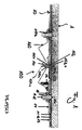
- FIG. 1 can be removed, has a cooking appliance according to the invention, which may be a garden pot, as he for example under the trade name VarioCookingCenter® is available, a crucible bottom 1, on which a heating plate 10 according to the invention is mounted with a thermocouple 100 according to the invention on.
- a cooking appliance according to the invention which may be a garden pot, as he for example under the trade name VarioCookingCenter® is available, a crucible bottom 1, on which a heating plate 10 according to the invention is mounted with a thermocouple 100 according to the invention on.
- the heating plate 10 in turn comprises a graphite foil 11 as a carrier layer and heat diffusion layer on the crucible bottom 1, a heating element 12 on the side remote from the crucible bottom 1 side of the graphite foil 11 and an insulating layer 13 on the side facing away from the graphite foil 11 of the heating element 12.
- the insulating layer 13 has two recesses 13a for two contact elements 18, see FIG. 2 in which current can be applied to the heating element 12 via the contact elements 18 via a current source (not shown) as a function of output data of a control device (not shown) connected to the thermocouple 100.
- the contact elements 18 are each attached via a screw connection to the crucible bottom 1, wherein each screw has a screw 21, a nut 20 and washers 19a to 19c.
- the contact elements 18 are arranged on two opposite sides of the heating plate 10, which in turn has a substantially rectangular periphery, on a center line of the rectangle of the heating plate 10th
- the heating plate 10 is in turn attached via a fastening device to the crucible bottom 1, which is a screw connection with four screws 15, in each case in operative connection with a nut 17 and two washers 14, 16.
- the rectangle of the heating plate 10 is divided into four rectangular sections, in each of which a screw 15 extends centrally, so as to achieve a uniform pressure of the heating plate 10 on the crucible bottom 1.
- at least one of the washers is formed enlarged, namely, the washer 14 is provided with a circular circumference extending over a majority of the respective rectangular portion of the rectangle of the heating plate 10, as shown in FIG FIG. 2 shown.
- thermocouple 100 is located centrally within the heating plate 10, equidistant from each of the four screws 15, as well as best in FIG FIG. 2 you can see.
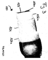
- the thermocouple 100 consists of a sleeve 101, a punch 102, a stainless steel plate 103 and cables 104a, 104b, see Figures 3 and 4 , More precisely, the stainless steel plate 103, which is essentially circular in plan view and represents the actual sensor, is arranged on a resting surface of a head 102a1 of the punch 102.
- the stainless steel plate 103 has on its side opposite the support surface of the head 102a1 side a contact surface for contacting the crucible bottom 1, as in FIG. 1 is shown on.
- two cables 104a are further welded on the side facing the support surface, which, isolated with PTFE, in regions 102b of the punch 102 are partially guided.
- the cables 104b are further insulated and protected by a sheath of silicone and extend between a stem 102a2 of the punch 102 and the sleeve 101 to finally exit the sleeve 101, see FIG. 3 .
- the cables 104a, 104b thus also serve to hold the sleeve 101 on the punch 102, namely in the region of the stem 102a2, which has a significantly smaller cross-section than the head 102a1 of the punch 102.
- the stamp 102 together with stainless steel plate 103 and cables 104a is in FIG. 3 to see introduced into the sleeve 101. Accordingly, the head 102a1 of the punch 102 rests on an end of the sleeve 101.
- the sleeve 101 is formed substantially hollow cylindrical, thus has a hollow cylinder 101b, with an inner diameter which is smaller than the outer diameter of the head 102a1 of the punch 102, but large enough for the harboring of the stem 102a2 of the punch 102 together with cable 104a.
- the sleeve 101 has an area with an enlarged diameter, which is referred to below collar 101 a.
- thermocouple 100 is fixed via a spring clip 110 relative to the crucible bottom 1, as in FIG. 1 shown.
- the heating plate 10 has for this purpose in addition to recesses 10a for the screws 15 a recess 10b for the thermocouple 100, so that the stainless steel plate 103 can contact the crucible bottom 1 with a defined contact surface.
- the spring clip 110 presses against the collar 101a of the sleeve 101 and thus ensures a defined contact pressure, while the design of the sleeve 101 and the ceramic stamp 102 ensures that lateral temperature influences on the thermocouple 100 by the heating plate 10 are negligible , In addition, the sleeve 101 and the punch 102, due to their poor heat conduction, ensure that substantially no thermal bridges can roll over the spring clip 110 to the stainless steel plate 103.
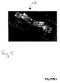
- the spring clip 110 is in FIG. 5 presented in detail and then includes seven subareas. Of these seven subregions, three are substantially planar and constitute pressure regions 111a, 111b1, 111b2, which are connected via bending edges 112a1 to 112b22 with prestressed, further subregions, two of which are substantially V-shaped in FIG. 5 extend upwards. At its two ends, the spring clip 110 thus has a respective pressure region 111b1, 111b2 with a hole 110b for fixing between washers 14 and 17 of the fastening device with nuts 15 tightened on the corresponding screws 15, see FIG.
- a partial region extending away from the heating plate 10 adjoins these first pressing regions 111b1, 111b2 via a bending edge 112b11, 112b12, to which, after another bending edge 112b21, 111b22, another subregion adjoins, which is inclined again to the heating plate 10 ,
- the two subregions inclined to the heating plate adjoin via bend edges 112a2 and 112a1 to a second, flat pressure region 112a.
- Double hole 110 a arranged in which the thermocouple 100 in FIG. 1 is shown fixed.
- thermocouple 100 For fixing the thermocouple 100 in the hole portion 110a2, the thermocouple 100, with its stainless steel plate 103 at first, is to be inserted into a first portion 110a1 of the second hole 110a until the collar 101a has passed through the first hole portion 110a1 of the spring clip 110. Then, the thermocouple 100 can be shifted into the second hole portion 110a2, so that the spring clip 110 rests on the collar 101a in the second pressing portion 111b, see FIG FIG. 1 , The spring clip 110 may be preassembled with either the thermocouple 100 and then secured between the washers 14 and 17.
- the spring clip 110 may be preassembled between the washers 14 and 17, but not clamped tightly, so that then the thermocouple 100 is connectable to the spring clip 110, and then by tightening the nuts 16 on the respective screws 15, the spring clip 110 firmly can be clamped.
- the inventive thermocouple 100 has a low mass of the individual components and is easy to assemble to measure with high accuracy, the surface temperature of the crucible bottom 1, so that on the crucible bottom 1, on the heating plate 10 side facing away, arranged, not shown Gargut, such as scrambled eggs or the like, on the crucible bottom 1 is uniformly heated.
Abstract
Description
Die vorliegende Erfindung betrifft ein Thermoelement, eine Heizplatte mit solch einem Thermoelement und ein Gargerät mit solch einer Heizplatte.The present invention relates to a thermocouple, a heating plate with such a thermocouple and a cooking appliance with such a heating plate.
Thermoelemente jeweils als Bestandteil eines Steuer- oder Regelkreises einer Heizeinrichtung zum Aufheizen einer Behälterwand sind im Stand der Technik gut bekannt. So offenbart beispielsweise die
Auch sind Heizplatten an sich im Stand der Technik gut bekannt, wobei hier insbesondere auf die
Gargeräte sind ebenfalls im Stand der Technik in unterschiedlichsten Ausführungsformen bekannt. So sind insbesondere Gartiegel, wie sie insbesondere unter dem Handelsnamen VarioCookingCenter® vertrieben werden, mit einer Heizplatte zum Aufheizen eines Tiegelbodens im Stand der Technik bekannt.Cooking appliances are also known in the prior art in various embodiments. Thus, in particular, cooking bars, such as those sold in particular under the trade name VarioCookingCenter®, with a heating plate for heating a crucible bottom are known in the prior art.
Aufgabe der vorliegenden Erfindung ist es, ein Thermoelement zu liefern, mit dem die Oberflächentemperatur einer Wand eines Garraums, insbesondere eines Tiegelbodens, mit hoher Genauigkeit erfassbar ist.Object of the present invention is to provide a thermocouple, with which the surface temperature of a wall of a cooking chamber, in particular a crucible bottom, can be detected with high accuracy.
Diese Aufgabe wird erfindungsgemäß gelöst durch ein Thermoelement mit zumindest einem Sensor zur Erfassung einer Oberflächentemperatur einer über zumindest eine Heizeinrichtung aufwärmbaren Wand, insbesondere eines Garraums, durch Kontaktieren der Wand mit einer Berührungsfläche und mit einem Halteglied, das lösbar mit der Wand unter Zwischenordnung einer Federeinrichtung verbindbar ist, um die Berührungsfläche des Sensors auf die Wand zu drücken, und zumindest teilweise aus einem thermischen Isolationsmaterial hergestellt ist, um Temperatureinflüsse von außerhalb der Berührungsfläche auf den Sensor zu reduzieren.This object is achieved by a thermocouple with at least one sensor for detecting a surface temperature of a heatable at least one heater wall, in particular a cooking chamber, by contacting the wall with a contact surface and a holding member which is releasably connectable to the wall with the interposition of a spring device is to press the contact surface of the sensor on the wall, and at least partially made of a thermal insulation material to reduce temperature influences from outside the contact surface on the sensor.
Dabei ist bevorzugt, dass die Berührungsfläche des Sensors im wesentlichen kreisförmig ist, und/oder die Berührungsfläche des Sensors durch ein Metallplättchen, insbesondere Edelstahlplättchen, bereitgestellt ist, und/oder die Berührungsfläche des Sensors durch das Zentrum eines plattenförmigen Heizelements der Heizeinrichtung hindurchführbar ist.It is preferred that the contact surface of the sensor is substantially circular, and / or the contact surface of the sensor is provided by a metal plate, in particular stainless steel plate, and / or the contact surface of the sensor can be passed through the center of a plate-shaped heating element of the heater.
Ferner wird vorgeschlagen, dass das Halteglied aus einer Keramik, insbesondere Stealan, und/oder zumindest zwei, insbesondere lösbar, miteinander verbindbaren Komponenten ausgebildet ist.It is also proposed that the holding member is formed of a ceramic, in particular Stealan, and / or at least two, in particular releasably, interconnectable components.
Dabei kann wiederum vorgesehen sein, dass die erste Komponente eine Auflagefläche für den Sensor, insbesondere das Metallplättchen, umfasst, und/oder stempelartig ausgebildet ist, und/oder zumindest teilweise in die zweite Komponente einführbar ist.It can again be provided that the first component comprises a bearing surface for the sensor, in particular the metal plate, and / or is formed like a stamp, and / or at least partially inserted into the second component.
Mit der Erfindung wird dabei zudem vorgeschlagen, dass die erste Komponente einen ersten, im wesentlichen zylinderförmigen Bereich mit einem ersten Querschnitt und einen zweiten, im wesentlichen zylinderförmigen Bereich mit einem zweiten Querschnitt, der geringer als der erste Querschnitt ist, umfasst, wobei der erste Bereich die Auflagefläche und zumindest eine Ausnehmung, vorzugsweise in Form eines sich längs des ersten Bereichs über den kompletten ersten Bereich erstreckenden Schlitzes, für zumindest ein Kabel des Sensors aufweist.The invention additionally proposes that the first component comprises a first, substantially cylindrical region with a first cross section and a second, essentially cylindrical region with a second cross section, which is smaller than the first cross section, wherein the first region the bearing surface and at least a recess, preferably in the form of a slot extending along the first area over the entire first area, for at least one cable of the sensor.
Ausführungsformen der Erfindung können dabei auch dadurch gekennzeichnet sein, dass das Metallplättchen des Sensors mit zwei Kabeln kontaktierbar ist, wobei vorzugsweise die Kabel auf der der Berührungsfläche abgewandten Seite des Metallplättchens aufgeschweißt sind und/oder in dem Schlitz, insbesondere in zwei diametral gegenüberliegenden Schlitzen, die sich zumindest teilweise in den zweiten Bereich der ersten Komponente verlängern, von der Auflagefläche der ersten Komponente und zumindest teilweise zwischen der ersten und zweiten Komponente geführt sind.Embodiments of the invention can also be characterized in that the metal plate of the sensor can be contacted with two cables, wherein preferably the cables are welded on the side facing away from the contact surface of the metal plate and / or in the slot, in particular in two diametrically opposed slots, the extend at least partially into the second region of the first component, are guided by the bearing surface of the first component and at least partially between the first and second components.
Mit der Erfindung wird ferner vorgeschlagen, dass die zweite Komponente des Halteglieds mit zwei offenen Enden und einem Innendurchmesser, der größer als der zweite Querschnitt des zweiten Bereichs der ersten Komponente und kleiner als der erste Querschnitt des ersten Bereichs der ersten Komponente ist, hülsenartig, insbesondere in Form eines Hohlzylinders ausgeformt ist, und die erste Komponente mit ihrem zweiten Bereich in die zweite Komponente einführbar ist, so dass an einem Ende der zweiten Komponente der erste Bereich der ersten Komponente angeordnet ist und aus dem zweiten Ende der zweiten Komponente die Kabel des Sensors hinausgeführt sind.With the invention it is further proposed that the second component of the holding member having two open ends and an inner diameter which is larger than the second cross section of the second region of the first component and smaller than the first cross section of the first region of the first component, sleeve-like, in particular is formed in the form of a hollow cylinder, and the first component is insertable with its second region in the second component, so that at one end of the second component, the first region of the first component is arranged and from the second end of the second component, the cable of the sensor led out.
Zudem kann vorgesehen sein, dass die zweite Komponente des Haltegliedes einen Anschlag zum Angreifen der Federeinrichtung bereitstellt, insbesondere in Form eines Kragens, wobei vorzugsweise der Hohlzylinder der zweiten Komponente mit einer sich radial nach außen erstreckenden Umfangsvergrößerung im Bereich des Anschlags ausgebildet ist.In addition, it can be provided that the second component of the holding member provides a stop for engaging the spring device, in particular in the form of a collar, wherein preferably the hollow cylinder of the second component is formed with a radially outwardly extending circumferential enlargement in the region of the stop.
Erfindungsgemäß wird auch vorgeschlagen, dass die Federeinrichtung über eine Befestigungseinrichtung an die Wand, insbesondere lösbar, anbringbar ist, wobei die Befestigungseinrichtung vorzugsweise auch der Befestigung des Heizelements der Heizeinrichtung an der Wand dient und/oder eine Schraubverbindung bereitstellt.According to the invention, it is also proposed that the spring device can be attached to the wall, in particular releasably, by means of a fastening device, wherein the fastening device preferably also serves for fastening the heating element of the heating device to the wall and / or provides a screw connection.
Die Erfindung liefert auch eine Heizplatte zum zumindest bereichsweisen Aufheizen der Wand, insbesondere eines Garraums eines Gargeräts, mit einer ersten Befestigungseinrichtung zum Befestigen zumindest eines Heizelements an der Wand und mit einer zweiten Befestigungseinrichtung zum Befestigen zumindest eines erfindungsgemäßen Thermoelements an der Wand.The invention also provides a heating plate for at least partially heating the wall, in particular a cooking chamber of a cooking appliance, with a first fastening device for fastening at least one heating element to the wall and with a second fastening device for fastening at least one thermocouple according to the invention on the wall.
Dabei kann eine Ausführungsform gekennzeichnet sein durch eine auf die Wand aufbringbare Trägerschicht, insbesondere in Form einer Graphitfolie, auf der, auf der der Wand gegenüberliegenden Seite, zumindest abschnittsweise, unmittelbar oder mittelbar, das Heizelement aufliegt und die der Vergleichmäßigung des Wärmeeintrags von dem Heizelement in die Wand dient, und/oder eine zumindest bereichsweise auf dem Heizelement auf seiner der Wand gegenüberliegenden Seite angeordnete Isolationsschicht, die vorzugsweise zumindest für eine Kontaktiereinrichtung des Heizelements eine Aussparung frei lässt.In this case, an embodiment may be characterized by a carrier layer which can be applied to the wall, in particular in the form of a graphite foil, on which the heating element rests on the side opposite the wall, at least in sections, directly or indirectly, and which homogenizes the heat input from the heating element the wall serves, and / or an insulating layer arranged at least in regions on the heating element on its side opposite the wall, which preferably leaves a recess free at least for a contacting device of the heating element.
Ferner werden mit der Erfindung Ausführungsformen vorgeschlagen, die gekennzeichnet sind durch zumindest eine erste Aussparung zum Hindurchführen zumindest eines Teils des Thermoelements und/oder zumindest eine zweite Aussparung zum Hindurchführen zumindest eines Teils der ersten Befestigungseinrichtung.Furthermore, embodiments are proposed with the invention, which are characterized by at least a first recess for passing at least a portion of the thermocouple and / or at least a second recess for passing at least a portion of the first fastening device.
Des weiteren kann vorgesehen sein, dass die erste Befestigungseinrichtung zumindest einen Teil der zweiten Befestigungseinrichtung bereitstellt, und/oder die zweite Befestigungseinrichtung die Federeinrichtung umfasst.Furthermore, it can be provided that the first fastening device provides at least a part of the second fastening device, and / or the second fastening device comprises the spring device.
Dabei kann auch vorgesehen sein, dass die erste Befestigungseinrichtung zumindest zwei Schrauben, vorzugsweise jeweils in Kooperation mit einer Mutter, und/oder zumindest zwei Bolzen umfasst, über die, insbesondere jeweils unter Zwischenlegung von zumindest einer Unterlegscheibe, das Heizelement, vorzugsweise die Trägerschicht, das Heizelement und die Isolationsschicht, gegen die Wand andrückbar ist.It can also be provided that the first fastening device comprises at least two screws, preferably in each case in cooperation with a nut, and / or at least two bolts, over which, in particular each with the interposition of at least one washer, the heating element, preferably the carrier layer, the Heating element and the insulating layer, against the wall is pressed.
Dabei wird vorgeschlagen, dass die Federeinrichtung zum Drücken der Berührungsfläche des Sensors des Thermoelements gegen die Wand über die Schrauben und/oder Bolzen anbringbar ist.It is proposed that the spring means for pressing the contact surface of the sensor of the thermocouple against the wall via the screws and / or bolts can be attached.
Erfindungsgemäß kann dabei zudem vorgesehen sein, dass die Heizplatte einen im wesentlichen rechteckigen Umfang aufweist, wobei vorzugsweise das Rechteck der Heizplatte in vier gleichgroße rechteckige Abschnitte aufteilbar ist, in jedem dieser Abschnitte eine Schraube oder ein Bolzen der ersten Befestigungseinrichtung angeordnet ist und die Federeinrichtung zwischen zwei auf einer Diagonalen des Rechtecks der Heizplatte angeordneten Schrauben oder Bolzen, mit letzteren verbunden, angeordnet ist, um das Thermoelement im Zentrum des Rechtecks der Heizplatte zu halten.According to the invention it can also be provided that the heating plate has a substantially rectangular circumference, wherein preferably the rectangle of the heating plate is divisible into four equal rectangular sections, in each of these sections a screw or bolt of the first fastening device is arranged and the spring means between two arranged on a diagonal of the rectangle of the heating plate screws or bolts, connected to the latter, is arranged to hold the thermocouple in the center of the rectangle of the heating plate.
Ausführungsformen der Erfindung können auch dadurch gekennzeichnet, dass die Federeinrichtung zumindest eine Federklemme oder Blattfeder umfasst, die an ihrem ersten Ende einen ersten ersten Bereich zum Angreifen der ersten Befestigungseinrichtung und an ihrem zweiten Ende einen zweiten ersten Bereich zum Angreifen der ersten Befestigungseinrichtung aufweist, wobei vorzugsweise im ersten und zweiten ersten Bereich jeweils ein erstes Loch zum Hindurchführen einer Schraube oder eines Bolzens bereitgestellt ist und/oder der erste und zweite erste Bereich jeweils einen ebenen Andrückbereich darstellt.Embodiments of the invention may also be characterized in that the spring device comprises at least one spring clip or leaf spring having at its first end a first first region for engaging the first fastening device and at its second end a second first region for engaging the first fastening device wherein in each case in the first and second first region in each case a first hole for passing a screw or a bolt is provided and / or the first and second first region each represents a flat pressing region.
Ferner kann vorgesehen sein, dass das Thermoelement in einem zweiten Bereich der Federklemme oder Blattfeder, der vorzugsweise im wesentlichen mittig zwischen dem ersten und zweiten ersten Bereich angeordnet ist, mit der Federklemme oder Blattfeder verbindbar ist, vorzugsweise durch Befestigung in einem zweiten Loch.Furthermore, it can be provided that the thermocouple in a second region of the spring clamp or leaf spring, which is preferably arranged substantially centrally between the first and second first region, is connectable to the spring clamp or leaf spring, preferably by attachment in a second hole.
Erfindungsgemäß kann dabei wiederum vorgesehen sein, dass das zweite Loch ein Doppelloch mit einem ersten Abschnitt, der einen Innendurchmesser aufweist, der zumindest dem Außendurchmesser des Kragens der zweiten Komponente des Halteglieds entspricht, und einem zweiten Abschnitt, der einen Innendurchmesser aufweist, der kleiner als der Außendurchmesser des Kragens und zumindest so groß wie der Außendurchmesser des Hohlzylinders der zweiten Komponente ist, umfasst.According to the invention, it can again be provided that the second hole has a double hole with a first section, which has an inner diameter which corresponds at least to the outer diameter of the collar of the second component of the retaining member, and a second section, which has an inner diameter which is smaller than that Outer diameter of the collar and at least as large as the outer diameter of the hollow cylinder of the second component is included.
Spezielle Ausführungsformen der Erfindung können dabei ferner dadurch gekennzeichnet sein, dass der zweite Bereich der Federklemme oder Blattfeder benachbart zum zweiten Abschnitt des zweiten Lochs einen ebenen Andrückbereich darstellt, wobei die Federklemme oder Blattfeder sich vorzugsweise zwischen zwei benachbarten ebenen Andrückbereichen im wesentlichen V-förmig, insbesondere von dem Heizelement weg, erstreckt.Special embodiments of the invention may be further characterized in that the second region of the spring clip or leaf spring adjacent to the second portion of the second hole is a flat pressure region, wherein the spring clip or leaf spring preferably between two adjacent planar Andrückbereichen substantially V-shaped, in particular away from the heating element.
Schließlich liefert die Erfindung auch ein Gargerät mit einem Garraum, insbesondere in Form eines Tiegels, der zumindest eine Wand, insbesondere einen Tiegelboden, mit zumindest einer erfindungsgemäßen Heizplatte umfasst, und mit einer Steuer- oder Regeleinrichtung zum Einstellen der Heizleistung der Heizplatte, die mit der Heizplatte, insbesondere über deren Kontaktiereinrichtung und mit einem erfindungsgemäßen Thermoelement, insbesondere dessen Kabel, verbindbar ist.Finally, the invention also provides a cooking appliance with a cooking chamber, in particular in the form of a crucible, comprising at least one wall, in particular a crucible bottom, with at least one heating plate according to the invention, and with a control or regulating device for adjusting the heating power of the heating plate, with the Heating plate, in particular via the contacting device and with a thermocouple according to the invention, in particular its cable, is connectable.
Der Erfindung liegt die überraschende Erkenntnis zugrunde, dass eine Berührungsfläche eines Sensors eines Thermoelements mit einer Wand, deren Oberflächentemperatur zu messen ist, insbesondere durch Anlegen einer definierten Anpresskraft komplett, kontaktierbar ist, und seitliche Temperatureinflüsse auf den Sensor, insbesondere durch Wärmestrahlung von einem die Wand aufheizenden Heizelement, ebenso wie Wärmebrücken, wie zwischen dem Sensor und einer das Thermoelement an der Wand haltenden Befestigungseinrichtung, durch Anordnen des Sensors an einem Halteglied mit einer schlechten Wärmeleitfähigkeit, also aus einem thermischen Isolationsmaterial im wesentlichen vermieden werden können, so dass die Oberflächentemperatur der Wand mit hoher Genauigkeit gemessen werden kann. Das erfindungsgemäße Thermoelement weist also eine definierte Berührungsfläche zum Kontaktieren besagter Wand auf. Das Halteglied des Thermoelements drückt zudem nach Art eines Stempels den Sensor unter Federvorspannung auf die Wand.The invention is based on the surprising finding that a contact surface of a sensor of a thermocouple with a wall whose surface temperature is to be measured, in particular completely by contacting a defined contact force, can be contacted, and lateral temperature influences on the sensor, in particular by thermal radiation of a wall heating element, as well as thermal bridges, as between the sensor and a thermocouple on the wall holding fastener, can be substantially avoided by arranging the sensor on a holding member having a poor thermal conductivity, ie from a thermal insulation material, so that the surface temperature of the wall can be measured with high accuracy. The thermoelement according to the invention thus has a defined contact surface for contacting said wall. The holding member of the thermocouple also presses the sensor under spring tension on the wall in the manner of a punch.
Vorzugsweise ist das Halteglied zweiteilig ausgeformt, und zwar mit einem in eine Hülse bereichsweise einschiebbaren Stempel, der den Sensor in Form eines Metallplättchens auf seinem Stempelkopf trägt. An das Metallplättchen können zwei Kabel angeschweißt sein, und zwar auf der der Berührungsfläche des Metallplättchens gegenüberliegenden Seite. Die Kabel können ferner voneinander getrennt zur Vermeidung mehrerer Messpunkte zuerst in Schlitzen des Stempelkopfs und dann zwischen dem Stiel des Stempels und der Hülse geführt werden. So können die Kabel auch die Hülse auf dem Stempel halten.Preferably, the holding member is formed in two parts, with a partially insertable into a sleeve stamp, which carries the sensor in the form of a metal plate on his stamp head. Two cables may be welded to the metal plate, on the side opposite the contact surface of the metal plate. The cables can also be separated from each other to avoid multiple measurement points are first performed in slots of the stamp head and then between the stem of the punch and the sleeve. So the cables can also hold the sleeve on the stamp.
Zum Drücken des Sensors unter Federvorspannung an die Wand kann eine Federklemme oder Blattfeder zum Einsatz kommen, die vorzugsweise über eine Befestigungseinrichtung des Heizelements auf der Wand anbringbar ist. Zur Befestigung des Thermoelements an der Federklemme oder Blattfeder weist letztere vorzugsweise ein Doppelloch auf, wobei ein erster, größerer Abschnitt des Doppellochs dem Einführen des Thermoelements und ein zweiter kleinerer Abschnitt dem Festklemmen des Thermoelements durch Angreifen an einen Kragen der Hülse dient.To press the sensor under spring tension on the wall, a spring clamp or leaf spring can be used, preferably via a fastening device of the Heating element is attachable to the wall. For attachment of the thermocouple to the spring clip or leaf spring, the latter preferably has a double hole, a first, larger portion of the double hole serving to insert the thermocouple and a second smaller portion to clamp the thermocouple by engaging a collar of the sleeve.
Weitere Merkmale und Vorteile der Erfindung ergeben sich aus der nachfolgenden Beschreibung, in der ein Ausführungsbeispiel der Erfindung beispielhaft anhand von schematischen Zeichnungen im Einzelnen erläutert ist. Dabei zeigt:
- Figur 1
- eine Teilschnittansicht durch ein erfindungsgemäßes Gargerät im Bereich eines Tiegelbodens mit einer erfindungsgemäßen Heizplatte und einem erfindungsgemäßen Thermoelement;
Figur 2- eine perspektivische Ansicht des Tiegelbodens samt Heizplatte und Thermoelement von
Figur 1 ; - Figur 3
- eine Seitenansicht des erfindungsgemäßen Thermoelements der
Figuren 1 und2 ; - Figur 4
- eine Seitenansicht einer Komponente des Thermoelements von
Figur 3 ; und - Figur 5
- eine perspektivische Ansicht einer Federklemme zur Fixierung des Thermoelements gemäß den
Figuren 1 bis 4 .
- FIG. 1
- a partial sectional view through an inventive cooking appliance in the region of a crucible bottom with a heating plate according to the invention and a thermocouple according to the invention;
- FIG. 2
- a perspective view of the crucible bottom, including heating plate and thermocouple of
FIG. 1 ; - FIG. 3
- a side view of the thermocouple of the invention
FIGS. 1 and2 ; - FIG. 4
- a side view of a component of the thermocouple of
FIG. 3 ; and - FIG. 5
- a perspective view of a spring clip for fixing the thermocouple according to the
FIGS. 1 to 4 ,
Wie
Die Heizplatte 10 umfasst ihrerseits eine Graphitfolie 11 als Trägerschicht sowie Wärmediffusionsschicht auf dem Tiegelboden 1, ein Heizelement 12 auf der von dem Tiegelboden 1 abgewandten Seite der Graphitfolie 11 und eine Isolationsschicht 13 auf der der Graphitfolie 11 abgewandten Seite des Heizelements 12. Die Isolationsschicht 13 weist zwei Aussparungen 13a für zwei Kontaktelemente 18 auf, siehe
Die Heizplatte 10 ist ihrerseits über eine Befestigungseinrichtung an dem Tiegelboden 1 angebracht, die eine Schraubverbindung mit vier Schrauben 15, jeweils in Wirkverbindung mit einer Mutter 17 und zwei Unterlegscheiben 14, 16, darstellt. Das Rechteck der Heizplatte 10 ist in vier rechteckige Abschnitte unterteilt, in denen jeweils eine Schraube 15 mittig verläuft, um so einen gleichmäßigen Andruck der Heizplatte 10 an dem Tiegelboden 1 zu erreichen. Zur weiteren Vergleichmäßigung des Andruckes der Heizplatte 10 an dem Tiegelboden 1 ist zumindest eine der Unterlegscheiben vergrößert ausgeformt, und zwar ist die Unterlegscheibe 14 mit einem kreisförmigen Umfang bereitgestellt, der sich über einen Großteil des jeweiligen rechteckigen Abschnitts des Rechtecks der Heizplatte 10 erstreckt, wie in
Das Thermoelement 100 ist mittig innerhalb der Heizplatte 10 angeordnet, und zwar mit gleichem Abstand zu jeder der vier Schrauben 15, wie auch am besten in
Das Thermoelement 100 besteht aus einer Hülse 101, einem Stempel 102, einem Edelstahlplättchen 103 und Kabeln 104a, 104b, siehe
Der Stempel 102 samt Edelstahlplättchen 103 und Kabeln 104a ist in
Das Thermoelement 100 ist über eine Federklemme 110 relativ zum Tiegelboden 1 fixierbar, wie in
Die Federklemme 110 ist in
Doppellochs 110a angeordnet, in dem das Thermoelement 100 in
Zur Fixierung des Thermoelements 100 in dem Lochabschnitt 110a2 ist das Thermoelement 100, mit seinem Edelstahlplättchen 103 zuerst, in einen ersten Abschnitt 110a1 des zweiten Loches 110a einzuführen, und zwar bis der Kragen 101a den ersten Lochabschnitt 110a1 der Federklemme 110 passiert hat. Sodann kann das Thermoelement 100 in den zweiten Lochabschnitt 110a2 verschoben werden, so dass die Federklemme 110 im zweiten Andrückbereich 111b auf dem Kragen 101a aufliegt, siehe
Das erfindungsgemäße Thermoelement 100 weist eine geringe Masse der einzelnen Komponenten auf und ist einfach montierbar, um mit hoher Genauigkeit die Oberflächentemperatur des Tiegelbodens 1 zu messen, so dass ein sich auf dem Tiegelboden 1, und zwar auf der der Heizplatte 10 abgewandten Seite, angeordnetes, nicht gezeigtes Gargut, wie Rührei oder dergleichen, über den Tiegelboden 1 gleichmäßig erhitzbar ist.The
Die in der vorstehenden Beschreibung, den Ansprüchen sowie den Zeichnungen offenbarten Merkmale können sowohl einzeln als auch in jeder beliebigen Kombination für die Verwirklichung der Erfindung in ihren verschiedenen Ausführungsformen wesentlich sein.The features disclosed in the foregoing description, the claims and the drawings may be essential both individually and in any combination for the realization of the invention in its various embodiments.
- 11
- Tiegelbodencrucible bottom
- 1010
- Heizplatteheating plate
- 10a, 10b10a, 10b
- Aussparungrecess
- 1111
- Graphitfoliegraphite foil
- 1212
- Heizelementheating element
- 1313
- Isolationsschichtinsulation layer
- 13a13a
- Aussparungrecess
- 1414
- Unterlegscheibewasher
- 1515
- Schraubescrew
- 1616
- Muttermother
- 1717
- Unterlegscheibewasher
- 1818
- Kontaktelementcontact element
- 19a, 19b, 19c19a, 19b, 19c
- Unterlegscheibewasher
- 2020
- Muttermother
- 2121
- Schraubescrew
- 100100
- Thermoelementthermocouple
- 101101
- Hülseshell
- 101a101
- Kragencollar
- 101b101b
- Hohlzylinderhollow cylinder
- 102102
- Stempelstamp
- 102a1102a1
- Kopfhead
- 102a2102a2
- Stielstalk
- 102b102b
- Schlitzslot
- 103103
- Edelstahlplättchenstainless steel plate
- 104a - 104c104a-104c
- Kabelelectric wire
- 110110
- Federklemmespring clip
- 110a, 110b1, 110b2110a, 110b1, 110b2
- Lochhole
- 110a1, 110a2110a1, 110a2
- Lochabschnitthole section
- 111 al - 111b22111 al-111b22
- Andrückbereichpressing area
- 112a1 - 112b22112a1 - 112b22
- Biegekantebending edge
Claims (21)
mit zumindest einem Sensor (103) zur Erfassung einer Oberflächentemperatur einer über zumindest eine Heizeinrichtung (10) aufwärmbaren Wand (1), insbesondere eines Garraums, durch Kontaktieren der Wand (1) mit einer Berührungsfläche und
mit einem Halteglied (101, 102), das lösbar mit der Wand (1) unter Zwischenordnung einer Federeinrichtung (110) verbindbar ist, um die Berührungsfläche des Sensors (103) auf die Wand (1) zu drücken, und zumindest teilweise aus einem thermischen Isolationsmaterial hergestellt ist, um Temperatureinflüsse von außerhalb der Berührungsfläche auf den Sensor (103) zu reduzieren.Thermocouple (100)
with at least one sensor (103) for detecting a surface temperature of a wall (1) which can be heated via at least one heating device (10), in particular a cooking chamber, by contacting the wall (1) with a contact surface and
with a holding member (101, 102) detachably connectable to the wall (1) with interposition of a spring means (110) for pressing the contact surface of the sensor (103) against the wall (1) and at least partially from a thermal Insulating material is made to reduce temperature influences from outside the contact surface on the sensor (103).
die Berührungsfläche des Sensors (103) im wesentlichen kreisförmig ist,
und/oder
die Berührungsfläche des Sensors durch ein Metallplättchen, insbesondere Edelstahlplättchen (103), bereitgestellt ist, und/oder
die Berührungsfläche des Sensors (103) durch das Zentrum eines plattenförmigen Heizelements (12) der Heizeinrichtung (10) hindurchführbar ist.Thermocouple according to claim 1, characterized in that
the contact surface of the sensor (103) is substantially circular,
and or
the contact surface of the sensor is provided by a metal plate, in particular stainless steel plate (103), and / or
the contact surface of the sensor (103) can be passed through the center of a plate-shaped heating element (12) of the heating device (10).
das Halteglied aus einer Keramik, insbesondere Stealan, und/oder zumindest zwei, insbesondere lösbar, miteinander verbindbaren Komponenten (101, 202) ausgebildet ist.Thermocouple according to claim 1 or 2, characterized in that
the holding member of a ceramic, in particular Stealan, and / or at least two, in particular releasably, interconnectable components (101, 202) is formed.
die erste Komponente (102) eine Auflagefläche für den Sensor (103), insbesondere das Metallplättchen, umfasst, und/oder stempelartig ausgebildet ist, und/oder zumindest teilweise in die zweite Komponente (103) einführbar ist.Thermocouple according to claim 3, characterized in that
the first component (102) comprises a bearing surface for the sensor (103), in particular the metal plate, and / or is formed like a stamp, and / or at least partially insertable into the second component (103).
die erste Komponente (102) einen ersten, im wesentlichen zylinderförmigen Bereich (102a1) mit einem ersten Querschnitt und einen zweiten, im wesentlichen zylinderförmigen Bereich (102a2) mit einem zweiten Querschnitt, der geringer als der erste Querschnitt ist, umfasst, wobei der erste Bereich (102a1) die Auflagefläche und zumindest eine Ausnehmung, vorzugsweise in Form eines sich längs des ersten Bereichs (102a1) über den kompletten ersten Bereich erstreckenden Schlitzes (102b), für zumindest ein Kabel (104a) des Sensors (103) aufweist.Thermocouple according to claim 4, characterized in that
the first component (102) comprises a first substantially cylindrical portion (102a1) having a first cross section and a second substantially cylindrical portion (102a2) having a second cross section which is smaller than the first cross section, the first portion (102a1) has the support surface and at least one recess, preferably in the form of a slot (102b) extending over the entire first region along the first region (102a1), for at least one cable (104a) of the sensor (103).
das Metallplättchen des Sensors (103) mit zwei Kabeln (104a) kontaktierbar ist, wobei vorzugsweise die Kabel (104a) auf der der Berührungsfläche abgewandten Seite des Metallplättchens aufgeschweißt sind und/oder in dem Schlitz (102b), insbesondere in zwei diametral gegenüberliegenden Schlitzen, die sich zumindest teilweise in den zweiten Bereich (102a2) der ersten Komponente (102) verlängern, von der Auflagefläche der ersten Komponente (102) und zunächst teilweise zwischen der ersten und zweiten Komponente (102, 101) geführt sind.Thermocouple according to claim 5, characterized in that
the metal plate of the sensor (103) can be contacted with two cables (104a), wherein preferably the cables (104a) are welded on the side of the metal plate facing away from the contact surface and / or in the slot (102b), in particular in two diametrically opposite slots, which at least partially extend into the second region (102a2) of the first component (102), are guided by the bearing surface of the first component (102) and initially partially between the first and second component (102, 101).
die zweite Komponente (101) des Halteglieds mit zwei offenen Enden und einem Innendurchmesser, der größer als der zweite Querschnitt des zweiten Bereichs (102a2) der ersten Komponente (102) und kleiner als der erste Querschnitt des ersten Bereichs (102a1) der ersten Komponente (102) ist, hülsenartig, insbesondere in Form eines Hohlzylinders (101b) ausgeformt ist, und die erste Komponente (102) mit ihrem zweiten Bereich (102a2) in die zweite Komponente (101) einführbar ist, so dass an einem Ende der zweiten Komponente (101) der erste Bereich (102a1) der ersten Komponente (102) angeordnet ist und aus dem zweiten Ende der zweiten Komponente (101) die Kabel (104b) des Sensors (103) hinausgeführt sind.Thermocouple according to claim 5 or 6, characterized in that
the second component (101) of the retaining member having two open ends and an inner diameter larger than the second cross section of the second region (102a2) the first component (102) and smaller than the first cross section of the first region (102a1) of the first component (102), sleeve-like, in particular in the form of a hollow cylinder (101b) is formed, and the first component (102) with its second region (102a2) in the second component (101) is insertable, so that at one end of the second component (101) of the first region (102a1) of the first component (102) is arranged and from the second end of the second component (101) Cable (104b) of the sensor (103) are led out.
die zweite Komponente (101) des Haltegliedes einen Anschlag zum Angreifen der Federeinrichtung (110) bereitstellt, insbesondere in Form eines Kragens (101a), wobei vorzugsweise der Hohlzylinder (101b) der zweiten Komponente (101) mit einer sich radial nach außen erstreckenden Umfangsvergrößerung im Bereich des Anschlags ausgebildet ist.Thermocouple according to one of claims 3 to 7, characterized in that
the second component (101) of the holding member provides a stop for engaging the spring means (110), in particular in the form of a collar (101a), preferably the hollow cylinder (101b) of the second component (101) having a radially outwardly extending circumferential enlargement Area of the stop is formed.
die Federeinrichtung (110) über eine Befestigungseinrichtung (14 - 17) an die Wand (1), insbesondere lösbar, anbringbar ist, wobei die Befestigungseinrichtung vorzugsweise auch der Befestigung des Heizelements (12) der Heizeinrichtung (10) an der Wand (1) dient und/oder eine Schraubverbindung bereitstellt.Thermocouple according to one of the preceding claims, characterized in that
the spring device (110) can be attached to the wall (1), in particular releasably, by a fastening device (14-17), wherein the fastening device preferably also serves to fasten the heating element (12) of the heating device (10) to the wall (1) and / or provides a screw connection.
mit einer ersten Befestigungseinrichtung (14 - 17) zum Befestigen zumindest eines Heizelements (12) an der Wand (1) und
mit einer zweiten Befestigungseinrichtung (14 - 17, 110) zum Befestigen zumindest eines Thermoelements (100) nach einem der vorangehenden Ansprüche an der Wand (1).Heating plate (10) for at least partially heating a wall (1), in particular a cooking chamber of a cooking appliance,
with a first fastening device (14-17) for fastening at least one heating element (12) to the wall (1) and
with a second fastening device (14-17, 110) for fastening at least one thermoelement (100) according to one of the preceding claims to the wall (1).
eine auf die Wand (1) aufbringbare Trägerschicht, insbesondere in Form einer Graphitfolie (11), auf der, auf der der Wand (1) gegenüberliegenden Seite, zumindest abschnittsweise, unmittelbar oder mittelbar, das Heizelement (12) aufliegt und die der Vergleichmäßigung des Wärmeeintrags von dem Heizelement (12) in die Wand (1) dient, und/oder
eine zumindest bereichsweise auf dem Heizelement (12) auf seiner der Wand (1) gegenüberliegenden Seite angeordnete Isolationsschicht (13), die vorzugsweise zumindest für eine Kontaktiereinrichtung (18) des Heizelements (12) eine Aussparung (13a) frei lässt.Heating plate according to claim 10, characterized by
a carrier layer, which can be applied to the wall (1), in particular in the form of a graphite foil (11), on which, on the wall (1) opposite side, at least in sections, directly or indirectly, the heating element (12) rests and the equalization of Heat input from the heating element (12) in the wall (1) is used, and / or
an insulating layer (13) arranged at least in regions on the heating element (12) on its side opposite to the wall (1), which preferably leaves free a recess (13a) at least for a contacting device (18) of the heating element (12).
zumindest eine erste Aussparung (10b) zum Hindurchführen zumindest eines Teils des Thermoelements (100) und/oder
zumindest eine zweite Aussparung (10a) zum Hindurchführen zumindest eines Teils der ersten Befestigungseinrichtung (14 - 17).Heating plate according to claim 10 or 11, characterized by
at least one first recess (10b) for passing at least a part of the thermocouple (100) and / or
at least one second recess (10a) for passing at least a part of the first fastening means (14-17).
die erste Befestigungseinrichtung (14 - 17) zumindest einen Teil der zweiten Befestigungseinrichtung (14 - 17, 110) bereitstellt, und/oder die zweite Befestigungseinrichtung (14 - 17, 110) die Federeinrichtung (110) umfasst.Heating plate according to one of claims 10 to 12, characterized in that
the first fastening device (14-17) provides at least part of the second fastening device (14-17, 110), and / or the second fastening device (14-17, 110) comprises the spring device (110).
die erste Befestigungseinrichtung zumindest zwei Schrauben (15), vorzugsweise jeweils in Kooperation mit einer Mutter (17), und/oder zumindest zwei Bolzen umfasst, über die, insbesondere jeweils unter Zwischenlegung von zumindest einer Unterlegscheibe (14, 16), das Heizelement (12), vorzugsweise die Trägerschicht (11), das Heizelement (12) und die Isolationsschicht (13), gegen die Wand (1) andrückbar ist.Heating plate according to claim 13, characterized in that
the first fastening device comprises at least two screws (15), preferably each in cooperation with a nut (17), and / or at least two bolts, via which, in particular in each case with the interposition of at least one washer (14, 16), the heating element (12 ), preferably the carrier layer (11), the heating element (12) and the insulating layer (13), against the wall (1) is pressed.
die Federeinrichtung (110) zum Drücken der Berührungsfläche des Sensors (103) des Thermoelements (100) gegen die Wand (1) über die Schrauben (15) und/oder Bolzen anbringbar ist.Heating plate according to claim 14, characterized in that
the spring means (110) for pressing the contact surface of the sensor (103) of the thermocouple (100) against the wall (1) via the screws (15) and / or bolts is attachable.
die Heizplatte (10) einen im wesentlichen rechteckigen Umfang aufweist, wobei vorzugsweise das Rechteck der Heizplatte (10) in vier gleichgroße rechteckige Abschnitte aufteilbar ist, in jedem dieser Abschnitte eine Schraube (15) oder ein Bolzen der ersten Befestigungseinrichtung (14 - 17) angeordnet ist und die Federeinrichtung (110) zwischen zwei auf einer Diagonalen des Rechtecks der Heizplatte (10) angeordneten Schrauben (15) oder Bolzen, mit letzteren verbunden, angeordnet ist, um das Thermoelement (100) im Zentrum des Rechtecks der Heizplatte (10) zu halten.Heating plate according to one of claims 10 to 15, characterized in that
the heating plate (10) has a substantially rectangular circumference, wherein preferably the rectangle of the heating plate (10) can be divided into four equally sized rectangular sections, in each of these sections a screw (15) or a bolt of the first fastening device (14-17) and the spring means (110) is disposed between two screws (15) or bolts disposed on a diagonal of the rectangle of the heating plate (10), connected to the latter, around the thermocouple (100) in the center of the rectangle of the heating plate (10) hold.
die Federeinrichtung zumindest eine Federklemme oder Blattfeder (110) umfasst, die an ihrem ersten Ende einen ersten ersten Bereich (111b1) zum Angreifen der ersten Befestigungseinrichtung (14 - 17) und an ihrem zweiten Ende einen zweiten ersten Bereich (111b2) zum Angreifen der ersten Befestigungseinrichtung (14 - 17) aufweist, wobei vorzugsweise im ersten und zweiten ersten Bereich (111b1, 111b2) jeweils ein erstes Loch (110b1, 110b2) zum Hindurchführen einer Schraube (15) oder eines Bolzens bereitgestellt ist und/oder der erste und zweite erste Bereich 111b1), 111b2) jeweils einen ebenen Andrückbereich darstellt.Heating plate according to one of claims 10 to 16, characterized in that
the spring means comprises at least one spring clip or leaf spring (110) having at its first end a first first region (111b1) for engaging the first attachment means (14-17) and at its second end a second first region (111b2) for engaging the first one Fastening device (14-17), wherein preferably in the first and second first region (111b1, 111b2) respectively a first hole (110b1, 110b2) for passing a screw (15) or a bolt is provided and / or the first and second first portion 111b1), 111b2) one each level pressing area represents.
das Thermoelement (100) in einem zweiten Bereich (111a) der Federklemme oder Blattfeder (110), der vorzugsweise im wesentlichen mittig zwischen dem ersten und zweiten ersten Bereich (111b1, 111b2) angeordnet ist, mit der Federklemme oder Blattfeder (110) verbindbar ist, vorzugsweise durch Befestigung in einem zweiten Loch (110a).Heating plate according to claim 17, characterized in that
the thermocouple (100) is connectable to the spring clip or leaf spring (110) in a second region (111a) of the spring clip or leaf spring (110), which is preferably located substantially centrally between the first and second first regions (111b1, 111b2) , preferably by attachment in a second hole (110a).
das zweite Loch (110a) ein Doppelloch mit einem ersten Abschnitt (110a1), der einen Innendurchmesser aufweist, der zumindest dem Außendurchmesser des Kragens (101a) der zweiten Komponente (101) des Halteglieds entspricht, und einem zweiten Abschnitt (110a2), der einen Innendurchmesser aufweist, der kleiner als der Außendurchmesser des Kragens (101a) und zumindest so groß wie der Außendurchmesser des Hohlzylinders (101b) der zweiten Komponente (101) ist, umfasst.Heating plate according to claim 18, characterized in that
the second hole (110a) has a double hole having a first portion (110a1) having an inner diameter at least equal to the outer diameter of the collar (101a) of the second component (101) of the support member, and a second portion (110a2) having a first portion Inner diameter which is smaller than the outer diameter of the collar (101 a) and at least as large as the outer diameter of the hollow cylinder (101 b) of the second component (101) comprises.
der zweite Bereich (111a) der Federklemme oder Blattfeder (110) benachbart zum zweiten Abschnitt (110a2) des zweiten Lochs (110a) einen ebenen Andrückbereich darstellt, wobei die Federklemme oder Blattfeder (110) sich vorzugsweise zwischen zwei benachbarten ebenen Andrückbereichen (111a - 111b2) im wesentlichen V-förmig, insbesondere von dem Heizelement (12) weg, erstreckt.Heating plate according to claim 19, characterized in that
the second portion (111a) of the spring clip or leaf spring (110) adjacent the second portion (110a2) of the second hole (110a) constitutes a flat pressing portion, the spring clip or leaf spring (110) preferably being sandwiched between two adjacent planar pressing portions (111a-111b2) ) substantially V-shaped, in particular away from the heating element (12).
mit einem Garraum, insbesondere in Form eines Tiegels, der zumindest eine Wand, insbesondere einen Tiegelboden (1), mit zumindest einer Heizplatte (10) nach einem der Ansprüche 10 bis 20 umfasst, und
mit einer Steuer- oder Regeleinrichtung zum Einstellen der Heizleistung der Heizplatte (10), die mit der Heizplatte (10), insbesondere über deren Kontaktiereinrichtung (18), und mit zumindest einem erfindungsgemäßen Thermoelement (100) nach einem der Ansprüche 1 bis 9, insbesondere über dessen Kabel (104b), verbindbar ist.Cooking appliance
with a cooking chamber, in particular in the form of a crucible, which comprises at least one wall, in particular a crucible bottom (1), with at least one heating plate (10) according to one of claims 10 to 20, and
with a control or regulating device for adjusting the heating power of the heating plate (10), with the heating plate (10), in particular via the contacting device (18), and with at least one thermoelement (100) according to any one of claims 1 to 9, in particular via the cable (104b), is connectable.
Priority Applications (1)
| Application Number | Priority Date | Filing Date | Title |
|---|---|---|---|
| EP20080290258 EP2131625B1 (en) | 2008-03-19 | 2008-03-19 | Cooking device with a cooking plate with a thermocouple element |
Applications Claiming Priority (1)
| Application Number | Priority Date | Filing Date | Title |
|---|---|---|---|
| EP20080290258 EP2131625B1 (en) | 2008-03-19 | 2008-03-19 | Cooking device with a cooking plate with a thermocouple element |
Publications (2)
| Publication Number | Publication Date |
|---|---|
| EP2131625A1 true EP2131625A1 (en) | 2009-12-09 |
| EP2131625B1 EP2131625B1 (en) | 2012-11-21 |
Family
ID=39591592
Family Applications (1)
| Application Number | Title | Priority Date | Filing Date |
|---|---|---|---|
| EP20080290258 Active EP2131625B1 (en) | 2008-03-19 | 2008-03-19 | Cooking device with a cooking plate with a thermocouple element |
Country Status (1)
| Country | Link |
|---|---|
| EP (1) | EP2131625B1 (en) |
Cited By (2)
| Publication number | Priority date | Publication date | Assignee | Title |
|---|---|---|---|---|
| EP2631545A1 (en) * | 2012-02-22 | 2013-08-28 | Electrolux Home Products Corporation N.V. | A heating plate including at least one temperature sensor element |
| ES2713382A1 (en) * | 2017-11-20 | 2019-05-21 | Bsh Electrodomesticos Espana Sa | COOKING FIELD WITH PROTECTION AGAINST OVERHEATING (Machine-translation by Google Translate, not legally binding) |
Families Citing this family (1)
| Publication number | Priority date | Publication date | Assignee | Title |
|---|---|---|---|---|
| US10429079B2 (en) | 2017-02-21 | 2019-10-01 | Zoppas Industries De Mexico S.A., De C.V. | Electric stovetop heater unit with integrated temperature control |
Citations (9)
| Publication number | Priority date | Publication date | Assignee | Title |
|---|---|---|---|---|
| US2727974A (en) * | 1953-04-09 | 1955-12-20 | Gen Electric | Electric heating apparatus |
| DE1141395B (en) * | 1961-03-14 | 1962-12-20 | Siemens Elektrogeraete Gmbh | Temperature sensor with temperature-dependent resistance |
| FR1514948A (en) * | 1965-05-21 | 1968-03-01 | Siemens Elektrogeraete Gmbh | Electric stove top |
| FR2350760A1 (en) * | 1976-05-06 | 1977-12-02 | Fischer Karl | ELECTRIC HEATING PLATE WITH TEMPERATURE LIMITER |
| US4241289A (en) * | 1979-03-02 | 1980-12-23 | General Electric Company | Heat sensing apparatus for an electric range automatic surface unit control |
| EP0021107A1 (en) * | 1979-06-13 | 1981-01-07 | E.G.O. Elektro-Geräte Blanc u. Fischer | Radiant heating element for a cooking unit equipped with temperature sensor |
| WO2005032214A2 (en) | 2003-09-16 | 2005-04-07 | Rational Ag | Heating element for cooking appliances |
| WO2006082383A1 (en) * | 2005-02-05 | 2006-08-10 | Ceramaspeed Limited | Electrical heating arrangement |
| EP1722661B1 (en) | 2004-03-12 | 2008-01-02 | Bialetti Industrie S.P.A. | A device for heating liquids, in particular milk |
-
2008
- 2008-03-19 EP EP20080290258 patent/EP2131625B1/en active Active
Patent Citations (9)
| Publication number | Priority date | Publication date | Assignee | Title |
|---|---|---|---|---|
| US2727974A (en) * | 1953-04-09 | 1955-12-20 | Gen Electric | Electric heating apparatus |
| DE1141395B (en) * | 1961-03-14 | 1962-12-20 | Siemens Elektrogeraete Gmbh | Temperature sensor with temperature-dependent resistance |
| FR1514948A (en) * | 1965-05-21 | 1968-03-01 | Siemens Elektrogeraete Gmbh | Electric stove top |
| FR2350760A1 (en) * | 1976-05-06 | 1977-12-02 | Fischer Karl | ELECTRIC HEATING PLATE WITH TEMPERATURE LIMITER |
| US4241289A (en) * | 1979-03-02 | 1980-12-23 | General Electric Company | Heat sensing apparatus for an electric range automatic surface unit control |
| EP0021107A1 (en) * | 1979-06-13 | 1981-01-07 | E.G.O. Elektro-Geräte Blanc u. Fischer | Radiant heating element for a cooking unit equipped with temperature sensor |
| WO2005032214A2 (en) | 2003-09-16 | 2005-04-07 | Rational Ag | Heating element for cooking appliances |
| EP1722661B1 (en) | 2004-03-12 | 2008-01-02 | Bialetti Industrie S.P.A. | A device for heating liquids, in particular milk |
| WO2006082383A1 (en) * | 2005-02-05 | 2006-08-10 | Ceramaspeed Limited | Electrical heating arrangement |
Cited By (3)
| Publication number | Priority date | Publication date | Assignee | Title |
|---|---|---|---|---|
| EP2631545A1 (en) * | 2012-02-22 | 2013-08-28 | Electrolux Home Products Corporation N.V. | A heating plate including at least one temperature sensor element |
| ES2713382A1 (en) * | 2017-11-20 | 2019-05-21 | Bsh Electrodomesticos Espana Sa | COOKING FIELD WITH PROTECTION AGAINST OVERHEATING (Machine-translation by Google Translate, not legally binding) |
| US11098905B2 (en) | 2017-11-20 | 2021-08-24 | BSH Hausgeräte GmbH | Hob with overheat control device |
Also Published As
| Publication number | Publication date |
|---|---|
| EP2131625B1 (en) | 2012-11-21 |
Similar Documents
| Publication | Publication Date | Title |
|---|---|---|
| EP1152639B1 (en) | Electrical heating unit, particularly for liquid supports | |
| EP3117112B1 (en) | Fastening system for assembling appliances, in particular electrical appliances | |
| EP0789503B1 (en) | Radiant heater | |
| EP2268101B1 (en) | Crucible base, cooking device and method for operating such a cooking device | |
| DE2744864B2 (en) | Device for fastening a probe in an opening of a container | |
| WO2001062048A1 (en) | Cooking surface comprising a temperature sensor | |
| EP0977223A2 (en) | Electrical switch | |
| EP0757210A1 (en) | Radiating cooker element | |
| WO2008148776A2 (en) | Device for determining and/or monitoring a measured value | |
| DE102020104410A1 (en) | Contact device, contact system and method for assembling such a contact system | |
| WO2018108195A1 (en) | Thermoelectric device | |
| EP2131625A1 (en) | N.a. | |
| DE2951072C2 (en) | Transition from a coaxial component to a microwave circuit arranged on a substrate | |
| DE10006954A1 (en) | Ceramic cooking hob has temperature sensor supported by fixing element extending from point on outside of heating element in contact with underside of hob surface on inside of heating element | |
| EP1865753A1 (en) | Heating element for a cooking device and cooking device equipped with one | |
| DE19514487A1 (en) | Radiator for a nozzle holder | |
| DE10155644B4 (en) | Device as a receiving cage for eyelets arranged on cable ends of a cable harness lugs | |
| EP3895291B1 (en) | Stator and electric machine | |
| EP0258590B1 (en) | Feed-through piece for connecting cables of an electric cooking plate | |
| DE4241242A1 (en) | Electrical condition sensor | |
| WO2017045769A1 (en) | Arrangement for connecting the lines of an electric cable, and electric device having such an arrangement | |
| EP0993014B1 (en) | Mounting of a switching device housing | |
| CH465963A (en) | Electrical temperature sensor for a gasoline injection device | |
| DE102010061553B4 (en) | Fastening element for a vibration damper with an annular absorber mass | |
| WO1996004536A1 (en) | Temperature sensor |
Legal Events
| Date | Code | Title | Description |
|---|---|---|---|
| PUAI | Public reference made under article 153(3) epc to a published international application that has entered the european phase |
Free format text: ORIGINAL CODE: 0009012 |
|
| AK | Designated contracting states |
Kind code of ref document: A1 Designated state(s): AT BE BG CH CY CZ DE DK EE ES FI FR GB GR HR HU IE IS IT LI LT LU LV MC MT NL NO PL PT RO SE SI SK TR |
|
| AX | Request for extension of the european patent |
Extension state: AL BA MK RS |
|
| 17P | Request for examination filed |
Effective date: 20100201 |
|
| AKX | Designation fees paid |
Designated state(s): DE FR IT |
|
| RAP1 | Party data changed (applicant data changed or rights of an application transferred) |
Owner name: FRIMA T SAS Owner name: RATIONAL AG |
|
| GRAP | Despatch of communication of intention to grant a patent |
Free format text: ORIGINAL CODE: EPIDOSNIGR1 |
|
| RIN1 | Information on inventor provided before grant (corrected) |
Inventor name: WASSMUS, REINHARD Inventor name: MINK, DIANA Inventor name: THOMEZEK, WOLFGANG Inventor name: DARENBERG, JOCHEN Inventor name: DOBSLAFF, WALDEMAR |
|
| GRAS | Grant fee paid |
Free format text: ORIGINAL CODE: EPIDOSNIGR3 |
|
| GRAP | Despatch of communication of intention to grant a patent |
Free format text: ORIGINAL CODE: EPIDOSNIGR1 |
|
| GRAA | (expected) grant |
Free format text: ORIGINAL CODE: 0009210 |
|
| AK | Designated contracting states |
Kind code of ref document: B1 Designated state(s): DE FR IT |
|
| REG | Reference to a national code |
Ref country code: DE Ref legal event code: R096 Ref document number: 502008008691 Country of ref document: DE Effective date: 20130117 |
|
| PG25 | Lapsed in a contracting state [announced via postgrant information from national office to epo] |
Ref country code: IT Free format text: LAPSE BECAUSE OF FAILURE TO SUBMIT A TRANSLATION OF THE DESCRIPTION OR TO PAY THE FEE WITHIN THE PRESCRIBED TIME-LIMIT Effective date: 20121121 |
|
| PLBE | No opposition filed within time limit |
Free format text: ORIGINAL CODE: 0009261 |
|
| STAA | Information on the status of an ep patent application or granted ep patent |
Free format text: STATUS: NO OPPOSITION FILED WITHIN TIME LIMIT |
|
| 26N | No opposition filed |
Effective date: 20130822 |
|
| REG | Reference to a national code |
Ref country code: DE Ref legal event code: R097 Ref document number: 502008008691 Country of ref document: DE Effective date: 20130822 |
|
| REG | Reference to a national code |
Ref country code: FR Ref legal event code: PLFP Year of fee payment: 9 |
|
| REG | Reference to a national code |
Ref country code: DE Ref legal event code: R082 Ref document number: 502008008691 Country of ref document: DE Representative=s name: JONES DAY RECHTSANWAELTE PATENTANWAELTE, DE Ref country code: DE Ref legal event code: R081 Ref document number: 502008008691 Country of ref document: DE Owner name: FRIMA INTERNATIONAL AG, CH Free format text: FORMER OWNERS: FRIMA - T SAS, WITTENHEIM, FR; RATIONAL AG, 86899 LANDSBERG, DE Ref country code: DE Ref legal event code: R081 Ref document number: 502008008691 Country of ref document: DE Owner name: RATIONAL AG, DE Free format text: FORMER OWNERS: FRIMA - T SAS, WITTENHEIM, FR; RATIONAL AG, 86899 LANDSBERG, DE |
|
| REG | Reference to a national code |
Ref country code: FR Ref legal event code: TQ Owner name: FRIMA INTERNATIONAL AG, CH Effective date: 20161108 Ref country code: FR Ref legal event code: TQ Owner name: RATIONAL AG, DE Effective date: 20161108 |
|
| REG | Reference to a national code |
Ref country code: FR Ref legal event code: PLFP Year of fee payment: 10 |
|
| REG | Reference to a national code |
Ref country code: FR Ref legal event code: PLFP Year of fee payment: 11 |
|
| PGFP | Annual fee paid to national office [announced via postgrant information from national office to epo] |
Ref country code: FR Payment date: 20230320 Year of fee payment: 16 |
|
| P01 | Opt-out of the competence of the unified patent court (upc) registered |
Effective date: 20230619 |
|
| PGFP | Annual fee paid to national office [announced via postgrant information from national office to epo] |
Ref country code: DE Payment date: 20240321 Year of fee payment: 17 |