EP2130956A1 - Apron cradle for spinning frames - Google Patents
Apron cradle for spinning frames Download PDFInfo
- Publication number
- EP2130956A1 EP2130956A1 EP09161642A EP09161642A EP2130956A1 EP 2130956 A1 EP2130956 A1 EP 2130956A1 EP 09161642 A EP09161642 A EP 09161642A EP 09161642 A EP09161642 A EP 09161642A EP 2130956 A1 EP2130956 A1 EP 2130956A1
- Authority
- EP
- European Patent Office
- Prior art keywords
- apron
- adjustors
- tensor
- aprons
- shaft
- Prior art date
- Legal status (The legal status is an assumption and is not a legal conclusion. Google has not performed a legal analysis and makes no representation as to the accuracy of the status listed.)
- Withdrawn
Links
- 238000009987 spinning Methods 0.000 title claims abstract description 20
- 239000000835 fiber Substances 0.000 description 6
- 238000000034 method Methods 0.000 description 4
- 238000003825 pressing Methods 0.000 description 3
- 238000005452 bending Methods 0.000 description 2
- 239000003086 colorant Substances 0.000 description 2
- 238000012423 maintenance Methods 0.000 description 2
- 239000011347 resin Substances 0.000 description 2
- 229920005989 resin Polymers 0.000 description 2
- 238000010586 diagram Methods 0.000 description 1
- 238000004519 manufacturing process Methods 0.000 description 1
- 239000002184 metal Substances 0.000 description 1
- 230000002093 peripheral effect Effects 0.000 description 1
Images

Classifications
-
- D—TEXTILES; PAPER
- D01—NATURAL OR MAN-MADE THREADS OR FIBRES; SPINNING
- D01H—SPINNING OR TWISTING
- D01H5/00—Drafting machines or arrangements ; Threading of roving into drafting machine
- D01H5/18—Drafting machines or arrangements without fallers or like pinned bars
- D01H5/70—Constructional features of drafting elements
- D01H5/86—Aprons; Apron supports; Apron tensioning arrangements
- D01H5/88—Cradles; Tensors
-
- D—TEXTILES; PAPER
- D01—NATURAL OR MAN-MADE THREADS OR FIBRES; SPINNING
- D01H—SPINNING OR TWISTING
- D01H5/00—Drafting machines or arrangements ; Threading of roving into drafting machine
- D01H5/18—Drafting machines or arrangements without fallers or like pinned bars
- D01H5/26—Drafting machines or arrangements without fallers or like pinned bars in which fibres are controlled by one or more endless aprons
-
- D—TEXTILES; PAPER
- D01—NATURAL OR MAN-MADE THREADS OR FIBRES; SPINNING
- D01H—SPINNING OR TWISTING
- D01H5/00—Drafting machines or arrangements ; Threading of roving into drafting machine
- D01H5/18—Drafting machines or arrangements without fallers or like pinned bars
- D01H5/70—Constructional features of drafting elements
- D01H5/86—Aprons; Apron supports; Apron tensioning arrangements
Definitions
- the present invention relates to an apron cradle for spinning frames, and more particularly, to an apron cradle used in a double-spindle type apron draft device attached to a weighting arm.
- a typical ring fine spinning frame includes an apron draft device arranged between a front roller and a back roller. Roving are held and drafted between a top apron and a bottom apron. Once assembled, the bottom apron is always held at the same predetermined position. However, the top apron is often arranged at a position spaced from the bottom apron when changing the spinning conditions or during maintenance. Furthermore, to facilitate maintenance, a draft device often employs a structure in which two top rollers, each including a top apron, is supported by a weighting arm in correspondence with two spindles. The top rollers may each be arranged at a draft position, in which the top rollers come into contact with the corresponding bottom rollers, and a standby position, in which the top rollers are spaced from the bottom rollers.
- the open amount between the distal ends of the top and bottom aprons must be adjusted in accordance with the yarn number count or fiber type.
- the interval between the apron cradle and tensor bar (hereafter referred to as tensor interval) must be adjusted.
- tensor interval To adjust the tensor interval at the left and right sides, a distance clip is attached to the distal portion of an apron cradle. The distance clip is attached to the apron cradle in a state in which the pressure applied by the weighting arm is cancelled.
- the distance clip is formed to correspond with one tensor interval.
- plural types of distance clips for different spinning conditions must always be prepared and stored. This causes difficulties in the management of the distance clips and increases manufacturing costs.
- Japanese Laid-Open Patent Publication No. 11-302930 proposes a distance clip that is applicable to a plurality of tensor intervals. When attaching the distance clip to the distal portion of an apron cradle, the positional relationship of the front and rear sides of the distance clip is varied so that the distance clip is applicable to two tensor intervals.
- Japanese Laid-Open Patent Publication No. 3-113025 describes a method for adjusting apron nip pressure in a draft device.
- an apron pressing member 52 is arranged on the distal portion of an apron tensioner 51.
- Left and right adjustment screws 53 are inserted through the apron pressing member 52 and extended to the surface of a tensor bar 54.
- the adjustment screws 53 vary the pressure produced between the apron pressing member 52 and the tensor bar 54.
- the pressure applied by the weighting arm does not have to be cancelled when adjusting the tensor interval.
- the problem with the distance clip does not occur.
- the adjustment screws 53 adjust the tensor interval in a continuous and stepless manner.
- the tensor interval does not necessarily have to be varied whenever the spinning conditions are changed.
- the same tensor interval may be used for yarns of which diameters are within a certain range.
- one aspect of the present invention provides an apron cradle for a spinning frame used in a double-spindle type apron draft device attached to a weighting arm.
- the apron cradle includes a support shaft, a main cradle body, two top aprons, two bottom aprons, a tensor bar, a shaft, and two adjustors.
- the support shaft is supported by the weighting arm.
- the main cradle body is supported by the support shaft.
- the two top aprons are supported by the main cradle body.
- the two bottom aprons are respectively correspond to the two top aprons.
- the tensor bar supports the two bottom aprons and is arranged facing toward the main cradle body.
- the shaft is arranged near a distal end of the main cradle body.
- the two adjustors are supported by the shaft at an eccentric position and arranged laterally outward from the weighting arm.
- Each of the adjustors includes a plurality of contact surfaces, each contactable with the tensor bar so that a tensor interval defined between the apron cradle and the tensor bar is adjustable in order to vary a gap in plural steps between a distal portion of the top aprons and a distal portion of the bottom aprons.
- a roller stand 11 supports a front bottom roller 12.
- a tensor bar 13 and a middle bottom roller 14 are arranged at the rear of the front bottom roller 12.
- Bottom aprons 15 run between the tensor bar 13 and the middle bottom roller 14.
- a weighting arm 16 is arranged above the bottom rollers 12 and 14.
- the weighting arm 16 has a distal end that supports front top rollers 17.
- a support arm 18 is fixed to the weighting arm 16 at the rear of the front top rollers 17.
- the support arm 18 has a distal end that supports the axially middle part of a support shaft 19 in a rotatable manner.
- Middle top rollers 20 are supported at the two ends of the support shaft 19 so as to be integrally rotatable with each other.
- the support shaft 19 supports an apron cradle 21.
- a top apron 22 runs between each of the middle top rollers 20 and the apron cradle 21.
- the apron cradle 21 includes a T-shaped main cradle body 23.
- the main cradle body 23 includes an arcuate portion 23a and a plate spring 23b.
- the arcuate portion 23a is formed near the basal end of the main cradle body 23 and is in contact with the peripheral surface of the support shaft 19.
- the plate spring 23b ( Figs. 1 and 3A ) is fixed to the central part of the main cradle body 23 and is in contact with the support arm 18 so as to urge the top apron 22 toward the bottom aprons 15 with the main cradle body 23.
- the main cradle body 23 has a distal end.
- Left and right apron guides 24 are fixed to the main cradle body 23 near the distal end.
- the top aprons 22 run between the middle top rollers 20 and the apron guides 24.
- the apron guides 24 each include stoppers 24a, which are spaced apart by a distance that is substantially the same as the width of the corresponding top apron 22 to restrict lateral movement of the top apron 22.
- the left and right aprons 22 are supported at symmetrical positions with respect to the weighting arm 16.
- a support 25 is arranged at the middle of the distal end of the main cradle body 23.
- the support 25 supports a shaft 26 in a rotatable manner.
- the shaft 26 has two ends projecting from the support 25 and located between the left and right top aprons 22.
- An adjustor 27 is fixed to each of the two ends of the shaft 26 to adjust the tensor interval.
- the adjustors 27 are rotated integrally with the shaft 26.
- the adjustors 27 are formed from metal, resin, or fiber reinforced resin.
- the adjustors 27 are each shaped to be generally octagonal when viewed from the side.
- One of the eight side surfaces of each adjustor 27 includes a groove 28.
- the adjustor 27 has four other side surfaces respectively defining contact surfaces 27a, 27b, 27c, and 27d, which come into contact with the tensor bar 13 and adjust the tensor interval.
- the adjustors 27 are supported by the shaft 26 laterally outward from the weighting arm 16 and between the left and right top aprons 22, which are supported by the main cradle body 23.
- the adjustors 27 are each fixed to the shaft 26 at an eccentric position so that the gap between the tensor bar 13 and the main cradle body 23, or the tensor interval, differs depending on which one of the contact surfaces 27a, 27b, 27c, and 27d is in contact with the tensor bar 13. That is, the adjustors 27 are each supported by the shaft 26 so that the distance from the center of the shaft 26 differs between the contact surfaces 27a, 27b, 27c, and 27d. Accordingly, the adjustors 27 come into contact with the tensor bar 13 so that the tensor interval is adjustable in plural steps.
- the adjustors 27 are each formed so that the tensor interval is largest when the tensor bar 13 is in contact with the contact surface 27a, second largest when in contact with the contact surface 27b, third largest when in contact with the contact surface 27c, and fourth largest when in contact with the contact surface 27d.
- the corners of the adjustors 27 are chamfered.
- the same tensor interval may be used if the diameters of the spinning yarns are within a constant range. Thus, the tensor interval does not have to be adjustable in a stepless manner.
- the adjustors 27 each include a colored portion to indicate which one of the contact surfaces 27a, 27b, 27c, and 27d is in contact with the tensor bar 13.
- the apron draft device In a state in which the pressure applied by the weighting arm 16 is cancelled, the apron cradle 21 holds the top aprons 22 in a state spaced apart from the bottom aprons 15.
- the weighting arm 16 When the weighting arm 16 is arranged at a pressure application position (spinning position) at which it presses each top roller toward the bottom rollers, the top aprons 22 comes into contact with the bottom aprons 15.
- the fiber bundles conveyed by the bottom aprons 15 and the top aprons 22 are held between the middle bottom roller 14 and the middle top rollers 20. In this state, the fiber bundles are stretched due to the difference of the rotation speed of the two front rollers 12 and 17 from the rotation speed of the aprons 15 and 22.
- the open amount between the distal ends of the bottom aprons 15 and the top aprons 22 must be adjusted in accordance with the yarn number count or fiber type. Thus, the tensor interval is adjusted to a suitable value that is in correspondence with the spinning conditions.
- the adjustors 27 are rotated so that the one of the contact surfaces 27a to 27d corresponding to the required tensor interval comes into contact with the tensor bar 13.
- the adjustors 27 are rotated by inserting an operation tool 30, such as the distal end of a slotted screwdriver, into the groove 28.
- an operation tool 30 such as the distal end of a slotted screwdriver
- the left and right adjustors 27 are rotated integrally with the shaft 26.
- the operation tool 30 is pivoted in the counterclockwise direction as viewed in Fig.
- the operation tool 30 is pivoted in the clockwise direction as viewed in Fig. 4 .
- the adjustors 27 are rotated until the contact surfaces that obtain the tensor interval suitable for the spinning conditions come into contact with the tensor bar 13.
- the operator checks whether the colored surface corresponding to the required tensor interval can be seen at the predetermined position. This enables the operator to obtain the required tensor interval.
- the adjustors 27 are rotated until the required colored surface can be seen at the predetermined position in each spindle, the adjustments are completed.
- the preferred embodiment has the advantages described below.
- the left and right adjustors 27 do not have to be integrally rotatable with the shaft 26 and may be supported by the shaft 26 to be independently rotatable.
- the support 25 of the main cradle body 23 does not have to rotatably support the shaft 26, which extends through the support 25.
- the shaft 26 does not have to be a single shaft commonly shared by the left and right adjustors 27. More specifically, separate coaxial shafts may be used in lieu of the shaft 26. This increases freedom for the configuration of the tensor interval adjustment compared to when the left and right adjustors 27 are integrally rotatable.
- the adjustors 27 are not limited to a structure that enables adjustment of the tensor interval in four steps and is only required to enable adjustment of the tensor interval in plural steps. That is, the adjustors 27 may be formed to enable adjustment of the tensor interval in three steps or less or five steps or more. It is however preferable that the adjustors 27 be adjustable in three or more steps.
- the adjustors 27 do not need to have an octagonal shape when viewed from the side.
- the adjustors 27 may have any number of surfaces that come into contact with the tensor bar 13 to enable adjustment of the tensor interval in plural steps.
- the adjustors 27 may each be a polygon having seven sides or less or a polygon having nine sides or more.
- the adjustors 27 do not have to be polygonal.
- the surfaces of the adjustors 27 other than the contact surfaces 27a to 27d may be curved.
- the operation portion used to rotate each adjustor 27 does not have to be the groove 28.
- a hole may be formed to receive one end of an operation member (operation tool 30) that rotates the adjustor 27.
- a projection may be formed in lieu of the groove 28. In this case, an operation member capable of holding the projection or an operation member having a recess engageable with the projection is used to rotate the adjustor 27.
- the operation portion of the polygonal adjustor 27 does not have to be formed on just one surface other than the contact surfaces 27a to 27d and may be formed on a plurality of surfaces. In this case, in comparison to when forming the operation portion on only one surface, the adjustor 27 is easier to rotate. Further, the operation portions do not all have to be formed by the grooves 28, holes, or projections. For example, as shown in Fig. 5B , a groove 28 may be formed on a surface other than the contact surfaces 27a to 27d, and a hole 31 may be formed in the contact surface 27b. Furthermore, an operation portion may be formed in the side surface of each of the adjustors 27.
- the operation tool 30 may include a plurality of engagement portions that are simultaneously engageable with the grooves 28, holes, or projections.
- an operation tool 30 including a plurality of engagement portions, which are arranged in a comb-like manner and spaced apart in accordance with the distance between the adjustors 27, may be used to simultaneously adjust the tensor interval with a plurality of the adjustors 27. In this case, the number of adjustment step can be reduced.
- each adjustor 27 may be eliminated.
- the stoppers 24a may be arranged on the upper surface of the main cradle body 23.
- the apron cradle of the preferred embodiment is not limited to the draft device of a fine spinning frame and may be applied to the draft device of a roving frame or a tying frame.
- An attachment which is detachably attached to the main cradle body 23, may be used to hold the support shaft 26 on the main cradle body 23.
- a support shaft (19) is supported by the weighting arm (16).
- a main cradle body (23) is supported by the support shaft (19) and supports top aprons (22). Bottom aprons (15) respectively correspond to the top aprons (22).
- a tensor bar (13) supports the bottom aprons (15) and is arranged facing toward the main cradle body (23).
- a shaft (26) arranged near a distal end of the main cradle body (23) supports adjustors (27, 27) laterally outward from the weighting arm (16).
- Each adjustor (27, 27) includes contact surfaces (27a, 27b, 27c, 27d) contactable with the tensor bar (13) so that a tensor interval between the apron cradle and tensor bar (13) is adjustable to vary a gap between distal portions of the top and bottom aprons.
Landscapes
- Engineering & Computer Science (AREA)
- Mechanical Engineering (AREA)
- Textile Engineering (AREA)
- Spinning Or Twisting Of Yarns (AREA)
Abstract
An apron cradle for a spinning frame of a double-spindle type apron draft device attached to a weighting arm (16). A support shaft (19) is supported by the weighting arm (16). A main cradle body (23) is supported by the support shaft (19) and supports top aprons (22). Bottom aprons (15) respectively correspond to the top aprons (22). A tensor bar (13) supports the bottom aprons (15) and is arranged facing toward the main cradle body (23). A shaft (26) arranged near a distal end of the main cradle body (23) supports adjustors (27, 27) laterally outward from the weighting arm (16). Each adjustor (27, 27) includes contact surfaces (27a, 27b, 27c, 27d) contactable with the tensor bar (13) so that a tensor interval between the apron cradle and tensor bar (13) is adjustable to vary a gap between distal portions of the top and bottom aprons.
Description
- The present invention relates to an apron cradle for spinning frames, and more particularly, to an apron cradle used in a double-spindle type apron draft device attached to a weighting arm.
- A typical ring fine spinning frame includes an apron draft device arranged between a front roller and a back roller. Roving are held and drafted between a top apron and a bottom apron. Once assembled, the bottom apron is always held at the same predetermined position. However, the top apron is often arranged at a position spaced from the bottom apron when changing the spinning conditions or during maintenance. Furthermore, to facilitate maintenance, a draft device often employs a structure in which two top rollers, each including a top apron, is supported by a weighting arm in correspondence with two spindles. The top rollers may each be arranged at a draft position, in which the top rollers come into contact with the corresponding bottom rollers, and a standby position, in which the top rollers are spaced from the bottom rollers.
- In such a draft device, the open amount between the distal ends of the top and bottom aprons must be adjusted in accordance with the yarn number count or fiber type. Thus, the interval between the apron cradle and tensor bar (hereafter referred to as tensor interval) must be adjusted. To adjust the tensor interval at the left and right sides, a distance clip is attached to the distal portion of an apron cradle. The distance clip is attached to the apron cradle in a state in which the pressure applied by the weighting arm is cancelled.
- The distance clip is formed to correspond with one tensor interval. Thus, plural types of distance clips for different spinning conditions must always be prepared and stored. This causes difficulties in the management of the distance clips and increases manufacturing costs. To solve this problem, Japanese Laid-Open Patent Publication No.
11-302930 - Japanese Laid-Open Patent Publication No.
3-113025 Figs. 6A and 6B , anapron pressing member 52 is arranged on the distal portion of anapron tensioner 51. Left andright adjustment screws 53 are inserted through theapron pressing member 52 and extended to the surface of atensor bar 54. Theadjustment screws 53 vary the pressure produced between theapron pressing member 52 and thetensor bar 54. - In the structure of Japanese Laid-Open Patent Publication No.
11-302930 - In the method described in Japanese Laid-Open Patent Publication No.
3-113025 3-113025 adjustment screws 53 adjust the tensor interval in a continuous and stepless manner. Thus, it is difficult to uniformly adjust the left and right tensor intervals. Further, there is a tendency for the tensor intervals to differ between spindles. The tensor interval does not necessarily have to be varied whenever the spinning conditions are changed. For example, the same tensor interval may be used for yarns of which diameters are within a certain range. Thus, even if a spinning yarn has a different diameter, there may be no need for the tensor interval to be adjustable in a stepless manner. - It is an object of the present invention to provide an apron cradle for a spinning frame that easily and uniformly adjusts left and right tensor intervals in an apron draft device without cancelling the pressure applied by a weighting arm.
- To achieve the above object, one aspect of the present invention provides an apron cradle for a spinning frame used in a double-spindle type apron draft device attached to a weighting arm. The apron cradle includes a support shaft, a main cradle body, two top aprons, two bottom aprons, a tensor bar, a shaft, and two adjustors. The support shaft is supported by the weighting arm. The main cradle body is supported by the support shaft. The two top aprons are supported by the main cradle body. The two bottom aprons are respectively correspond to the two top aprons. The tensor bar supports the two bottom aprons and is arranged facing toward the main cradle body. The shaft is arranged near a distal end of the main cradle body. The two adjustors are supported by the shaft at an eccentric position and arranged laterally outward from the weighting arm. Each of the adjustors includes a plurality of contact surfaces, each contactable with the tensor bar so that a tensor interval defined between the apron cradle and the tensor bar is adjustable in order to vary a gap in plural steps between a distal portion of the top aprons and a distal portion of the bottom aprons.
- Other aspects and advantages of the present invention will become apparent from the following description, taken in conjunction with the accompanying drawings, illustrating by way of example the principles of the invention.
- The invention, together with objects and advantages thereof, may best be understood by reference to the following description of the presently preferred embodiments together with the accompanying drawings in which:
-
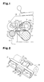
Fig. 1 is a side view showing a preferred embodiment of a draft device according to the present invention; -
Fig. 2 is a schematic perspective view of an apron cradle shown inFig. 1 ; -
Fig. 3A is a schematic diagram of the apron cradle shown inFig. 1 taken from a diagonally upward position; -
Fig. 3B is a schematic cross-sectional view showing the relationship between an adjustor and a tensor bar; -
Fig. 4 is a schematic cross-sectional view showing the relationship between the adjustor and an operation tool; -
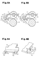
Figs. 5A and 5B are schematic cross-sectional views showing adjustors in further embodiments: -
Fig. 6A is a schematic perspective view showing the prior art; and -
Fig. 6B is a schematic partial perspective view showing the prior art. - A preferred embodiment of a double-spindle type apron draft device for a fine spinning frame according to the present invention will now be discussed with reference to
Figs. 1 to 4 . - Referring to
Fig. 1 , aroller stand 11 supports afront bottom roller 12. Atensor bar 13 and amiddle bottom roller 14 are arranged at the rear of thefront bottom roller 12.Bottom aprons 15 run between thetensor bar 13 and themiddle bottom roller 14. - A
weighting arm 16 is arranged above thebottom rollers weighting arm 16 has a distal end that supports fronttop rollers 17. Asupport arm 18 is fixed to theweighting arm 16 at the rear of the fronttop rollers 17. Thesupport arm 18 has a distal end that supports the axially middle part of asupport shaft 19 in a rotatable manner. Middletop rollers 20 are supported at the two ends of thesupport shaft 19 so as to be integrally rotatable with each other. Thesupport shaft 19 supports anapron cradle 21. Atop apron 22 runs between each of the middletop rollers 20 and theapron cradle 21. - As shown in
Figs. 2 and3A , theapron cradle 21 includes a T-shapedmain cradle body 23. Referring toFigs. 1 and 2 , themain cradle body 23 includes anarcuate portion 23a and aplate spring 23b. Thearcuate portion 23a is formed near the basal end of themain cradle body 23 and is in contact with the peripheral surface of thesupport shaft 19. Theplate spring 23b (Figs. 1 and3A ) is fixed to the central part of themain cradle body 23 and is in contact with thesupport arm 18 so as to urge thetop apron 22 toward thebottom aprons 15 with themain cradle body 23. Themain cradle body 23 has a distal end. Left and right apron guides 24 are fixed to themain cradle body 23 near the distal end. Thetop aprons 22 run between the middletop rollers 20 and the apron guides 24. The apron guides 24 each includestoppers 24a, which are spaced apart by a distance that is substantially the same as the width of the correspondingtop apron 22 to restrict lateral movement of thetop apron 22. The left andright aprons 22 are supported at symmetrical positions with respect to theweighting arm 16. - A
support 25 is arranged at the middle of the distal end of themain cradle body 23. Thesupport 25 supports ashaft 26 in a rotatable manner. Theshaft 26 has two ends projecting from thesupport 25 and located between the left and righttop aprons 22. Anadjustor 27 is fixed to each of the two ends of theshaft 26 to adjust the tensor interval. Theadjustors 27 are rotated integrally with theshaft 26. Although not particularly limited, theadjustors 27 are formed from metal, resin, or fiber reinforced resin. - As shown in
Fig. 3B , theadjustors 27 are each shaped to be generally octagonal when viewed from the side. One of the eight side surfaces of eachadjustor 27 includes agroove 28. Theadjustor 27 has four other side surfaces respectively definingcontact surfaces tensor bar 13 and adjust the tensor interval. Theadjustors 27 are supported by theshaft 26 laterally outward from theweighting arm 16 and between the left and righttop aprons 22, which are supported by themain cradle body 23. Theadjustors 27 are each fixed to theshaft 26 at an eccentric position so that the gap between thetensor bar 13 and themain cradle body 23, or the tensor interval, differs depending on which one of the contact surfaces 27a, 27b, 27c, and 27d is in contact with thetensor bar 13. That is, theadjustors 27 are each supported by theshaft 26 so that the distance from the center of theshaft 26 differs between the contact surfaces 27a, 27b, 27c, and 27d. Accordingly, theadjustors 27 come into contact with thetensor bar 13 so that the tensor interval is adjustable in plural steps. - In the preferred embodiment, the
adjustors 27 are each formed so that the tensor interval is largest when thetensor bar 13 is in contact with thecontact surface 27a, second largest when in contact with thecontact surface 27b, third largest when in contact with thecontact surface 27c, and fourth largest when in contact with thecontact surface 27d. To facilitate rotation, the corners of theadjustors 27 are chamfered. Further, even if spinning yarns have different diameters, the same tensor interval may be used if the diameters of the spinning yarns are within a constant range. Thus, the tensor interval does not have to be adjustable in a stepless manner. - The
adjustors 27 each include a colored portion to indicate which one of the contact surfaces 27a, 27b, 27c, and 27d is in contact with thetensor bar 13. Four of the adjustor side surfaces that would be located at a predetermined position, which an operator may easily view, when the contact surfaces 27a, 27b, 27c, and 27d are in contact with thetensor bar 13 are colored with different colors to define the colored portion. - The operation of the apron draft device will now be discussed. In a state in which the pressure applied by the
weighting arm 16 is cancelled, theapron cradle 21 holds thetop aprons 22 in a state spaced apart from thebottom aprons 15. When theweighting arm 16 is arranged at a pressure application position (spinning position) at which it presses each top roller toward the bottom rollers, thetop aprons 22 comes into contact with thebottom aprons 15. - Rotation of the
middle bottom roller 14 rotates thebottom aprons 15. Friction between thetop aprons 22 and thebottom aprons 15 rotate thetop aprons 22 synchronously with thebottom aprons 15. This conveys fiber bundles (not shown) on thebottom aprons 15. The moving portion of eachtop apron 22 located at the upper side is guided by thestoppers 24a of thecorresponding apron guide 24. Thus, thetop apron 22 rotates at a predetermined position in a state in which lateral movement is restricted. - The fiber bundles conveyed by the
bottom aprons 15 and thetop aprons 22 are held between themiddle bottom roller 14 and the middletop rollers 20. In this state, the fiber bundles are stretched due to the difference of the rotation speed of the twofront rollers aprons bottom aprons 15 and thetop aprons 22 must be adjusted in accordance with the yarn number count or fiber type. Thus, the tensor interval is adjusted to a suitable value that is in correspondence with the spinning conditions. - To adjust the tensor interval, the
adjustors 27 are rotated so that the one of the contact surfaces 27a to 27d corresponding to the required tensor interval comes into contact with thetensor bar 13. As shown inFig. 4 , theadjustors 27 are rotated by inserting anoperation tool 30, such as the distal end of a slotted screwdriver, into thegroove 28. When moving theoperation tool 30 in a state in which its distal end is inserted into thegroove 28, the left andright adjustors 27 are rotated integrally with theshaft 26. For example, to rotate theadjustors 27 from the state ofFig. 4 until the contact surfaces 27a come into contact with thetensor bar 13, theoperation tool 30 is pivoted in the counterclockwise direction as viewed inFig. 4 . To rotate theadjustors 27 until the contact surfaces 27c or 27d come into contact with thetensor bar 13, theoperation tool 30 is pivoted in the clockwise direction as viewed inFig. 4 . Theadjustors 27 are rotated until the contact surfaces that obtain the tensor interval suitable for the spinning conditions come into contact with thetensor bar 13. When rotating theadjustors 27, the operator checks whether the colored surface corresponding to the required tensor interval can be seen at the predetermined position. This enables the operator to obtain the required tensor interval. When theadjustors 27 are rotated until the required colored surface can be seen at the predetermined position in each spindle, the adjustments are completed. - The preferred embodiment has the advantages described below.
- (1) The
apron cradle 21 includes themain cradle body 23 supported by thesupport shaft 19, which is supported by theweighting arm 16. Theshaft 26 located near the distal end of themain cradle body 23 supports the left andright adjustors 27. Theadjustors 27 come into contact with thetensor bar 13 laterally outward from theweighting arm 16 and enable the gap between the distal portions of thetop aprons 22 and the distal portions of thebottom aprons 15 to be adjusted in plural steps. The tensor interval is adjusted by rotating the left andright adjustors 27 without cancelling the pressure applied by theweighting arm 16. Accordingly, the tensor interval of the apron draft device at the left and right sides is easily and uniformly adjusted without cancelling the pressure applied by theweighting arm 16. - (2) The left and
right adjustors 27 are fixed to theshaft 26 in an integrally rotatable manner. Accordingly, rotation of one of theadjustors 27 simultaneously rotates theother adjustor 27 together with theshaft 26. This reduces the tasks for adjusting the tensor interval by one half compared to when the twoadjustors 27 are independently rotatable. - (3) The left and
right adjustors 27 are arranged between the left and righttop aprons 22, which are supported by themain cradle body 23. Accordingly, in comparison with when the left andright adjustors 27 are arranged outward from the top aprons, the bending moment acting on themain cradle body 23 is reduced. That is, the bending moment acting on themain cradle body 23 is prevented from increasing. - (4) Each
adjustor 27 includes thegroove 28, which functions as an operation portion. In a a state in which the end of the operation tool 30 (e.g., screwdriver) is engaged with thegroove 28, theadjustor 27 may easily be rotated by applying force to theoperation tool 30. - (5) Each
adjustor 27 includes the colored portion, which indicates which one of the contact surfaces 27a, 27b, 27c, and 27d is in contact with thetensor bar 13. Four of the adjustor side surfaces that would be located at a predetermined position, which an operator may easily view, when the contact surfaces 27a, 27b, 27c, and 27d are in contact with thetensor bar 13 are colored with different colors to define the colored portion. When adjusting the tensor interval, theadjustors 27 are rotated until the surface having the color corresponding to the required tensor interval is arranged at the predetermined position, which can easily be seen by the operator. This allows all of theadjustors 27 to be arranged in a state corresponding to the required tensor interval. - It should be apparent to those skilled in the art that the present invention may be embodied in many other specific forms without departing from the spirit or scope of the invention. Particularly, it should be understood that the present invention may be embodied in the following forms.
- The left and
right adjustors 27 do not have to be integrally rotatable with theshaft 26 and may be supported by theshaft 26 to be independently rotatable. In this case, thesupport 25 of themain cradle body 23 does not have to rotatably support theshaft 26, which extends through thesupport 25. Further, theshaft 26 does not have to be a single shaft commonly shared by the left andright adjustors 27. More specifically, separate coaxial shafts may be used in lieu of theshaft 26. This increases freedom for the configuration of the tensor interval adjustment compared to when the left andright adjustors 27 are integrally rotatable. - The
adjustors 27 are not limited to a structure that enables adjustment of the tensor interval in four steps and is only required to enable adjustment of the tensor interval in plural steps. That is, theadjustors 27 may be formed to enable adjustment of the tensor interval in three steps or less or five steps or more. It is however preferable that theadjustors 27 be adjustable in three or more steps. - The
adjustors 27 do not need to have an octagonal shape when viewed from the side. Theadjustors 27 may have any number of surfaces that come into contact with thetensor bar 13 to enable adjustment of the tensor interval in plural steps. For example, theadjustors 27 may each be a polygon having seven sides or less or a polygon having nine sides or more. Further, theadjustors 27 do not have to be polygonal. For example, as shown inFig. 5A , the surfaces of theadjustors 27 other than the contact surfaces 27a to 27d may be curved. - The operation portion used to rotate each
adjustor 27 does not have to be thegroove 28. For example, a hole may be formed to receive one end of an operation member (operation tool 30) that rotates theadjustor 27. Further, a projection may be formed in lieu of thegroove 28. In this case, an operation member capable of holding the projection or an operation member having a recess engageable with the projection is used to rotate theadjustor 27. - The operation portion of the
polygonal adjustor 27 does not have to be formed on just one surface other than the contact surfaces 27a to 27d and may be formed on a plurality of surfaces. In this case, in comparison to when forming the operation portion on only one surface, theadjustor 27 is easier to rotate. Further, the operation portions do not all have to be formed by thegrooves 28, holes, or projections. For example, as shown inFig. 5B , agroove 28 may be formed on a surface other than the contact surfaces 27a to 27d, and ahole 31 may be formed in thecontact surface 27b. Furthermore, an operation portion may be formed in the side surface of each of theadjustors 27. - The
operation tool 30 may include a plurality of engagement portions that are simultaneously engageable with thegrooves 28, holes, or projections. For example, anoperation tool 30 including a plurality of engagement portions, which are arranged in a comb-like manner and spaced apart in accordance with the distance between theadjustors 27, may be used to simultaneously adjust the tensor interval with a plurality of theadjustors 27. In this case, the number of adjustment step can be reduced. - The colored portion of each adjustor 27 may be eliminated.
- Instead of fixing the apron guides 24 to the
main cradle body 23, thestoppers 24a may be arranged on the upper surface of themain cradle body 23. - The apron cradle of the preferred embodiment is not limited to the draft device of a fine spinning frame and may be applied to the draft device of a roving frame or a tying frame.
- An attachment, which is detachably attached to the
main cradle body 23, may be used to hold thesupport shaft 26 on themain cradle body 23. - The present examples and embodiments are to be considered as illustrative and not restrictive, and the invention is not to be limited to the details given herein, but may be modified within the scope and equivalence of the appended claims.
- An apron cradle for a spinning frame of a double-spindle type apron draft device attached to a weighting arm (16). A support shaft (19) is supported by the weighting arm (16). A main cradle body (23) is supported by the support shaft (19) and supports top aprons (22). Bottom aprons (15) respectively correspond to the top aprons (22). A tensor bar (13) supports the bottom aprons (15) and is arranged facing toward the main cradle body (23). A shaft (26) arranged near a distal end of the main cradle body (23) supports adjustors (27, 27) laterally outward from the weighting arm (16). Each adjustor (27, 27) includes contact surfaces (27a, 27b, 27c, 27d) contactable with the tensor bar (13) so that a tensor interval between the apron cradle and tensor bar (13) is adjustable to vary a gap between distal portions of the top and bottom aprons.
Claims (7)
- An apron cradle for a spinning frame used in a double-spindle type apron draft device attached to a weighting arm (16), the apron cradle comprising:a support shaft (19) supported by the weighting arm (16);a main cradle body (23) supported by the support shaft (19);two top aprons (22) supported by the main cradle body (23);two bottom aprons (15) respectively corresponding to the two top aprons (22); anda tensor bar (13) which supports the two bottom aprons (15) and which is arranged facing toward the main cradle body (23), being characterized by:a shaft (26) arranged near a distal end of the main cradle body (23); andtwo adjustors (27, 27) supported by the shaft (26) at an eccentric position and arranged laterally outward from the weighting arm (16), each of the adjustors (27, 27) including a plurality of contact surfaces (27a, 27b, 27c, 27d), each contactable with the tensor bar (13) so that a tensor interval defined between the apron cradle and the tensor bar (13) is adjustable in order to vary a gap in plural steps between a distal portion of the top aprons (22) and a distal portion of the bottom aprons (15).
- The apron cradle according to claim 1, being characterized in that each of the adjustors (27, 27) is supported by the shaft (26) so that the distance from the center of the shaft (26) differs between the plurality of contact surfaces (27a, 27b, 27c, 27d).
- The apron cradle according to claim 1 or 2, being characterized in that the two adjustors (27, 27) are fixed to the shaft (26) so as to be integrally rotatable with each other.
- The apron cradle according to claim 1 or 2, being characterized in that the two adjustors (27, 27) are supported by the shaft so as to be rotatable independently from each other.
- The apron cradle according to any one of claims 1 to 4, being characterized in that the two adjustors (27, 27) are arranged between the two top aprons supported by the main cradle body (23).
- The apron cradle according to any one of claims 1 to 5, being characterized in that the adjustors (27, 27) each include a colored portion to indicate which one of the plurality of contact surfaces (27a, 27b, 27c, 27d) is in contact with the tensor bar.
- The apron cradle according to any one of claims 1 to 6, being characterized in that the adjustors (27, 27) each include an operation portion (28, 31) used to rotate the adjustor (27).
Applications Claiming Priority (1)
| Application Number | Priority Date | Filing Date | Title |
|---|---|---|---|
| JP2008145912A JP2009293143A (en) | 2008-06-03 | 2008-06-03 | Apron cradle of loom |
Publications (1)
| Publication Number | Publication Date |
|---|---|
| EP2130956A1 true EP2130956A1 (en) | 2009-12-09 |
Family
ID=41100732
Family Applications (1)
| Application Number | Title | Priority Date | Filing Date |
|---|---|---|---|
| EP09161642A Withdrawn EP2130956A1 (en) | 2008-06-03 | 2009-06-02 | Apron cradle for spinning frames |
Country Status (3)
| Country | Link |
|---|---|
| EP (1) | EP2130956A1 (en) |
| JP (1) | JP2009293143A (en) |
| CN (1) | CN101597822A (en) |
Cited By (3)
| Publication number | Priority date | Publication date | Assignee | Title |
|---|---|---|---|---|
| CN101876110A (en) * | 2010-07-30 | 2010-11-03 | 宁波民丰实业有限公司 | Full carbon fiber top pin with plug-in tail structure and manufacturing method thereof |
| CN107326483A (en) * | 2017-08-14 | 2017-11-07 | 张家港市广大纺机有限公司 | A kind of novel spinning reel cage |
| CN107354542A (en) * | 2017-08-14 | 2017-11-17 | 张家港市广大纺机有限公司 | A kind of reel cage of fast positioning pressue device |
Families Citing this family (1)
| Publication number | Priority date | Publication date | Assignee | Title |
|---|---|---|---|---|
| EP3461938B1 (en) * | 2017-09-29 | 2021-09-29 | Pinter Caipo, S.A.U. | Cradle assembly for a drafting device of a spinning machine |
Citations (6)
| Publication number | Priority date | Publication date | Assignee | Title |
|---|---|---|---|---|
| JPH03113025A (en) | 1989-09-28 | 1991-05-14 | Murata Mach Ltd | Method for controlling apron nip pressure of draft device |
| EP0450361A1 (en) * | 1990-04-06 | 1991-10-09 | Maschinenfabrik Rieter Ag | Drafting arrangement with at least one drafting apron |
| DE19916375A1 (en) * | 1998-04-20 | 1999-10-21 | Toyoda Automatic Loom Works | Spacer clip for the belt cage of a drawing unit with continuous belts |
| DE10234599A1 (en) * | 2001-07-31 | 2003-02-13 | Rieter Ag Maschf | Twin-belt sliver drawing unit, for a ring spinner/flyer, has an eccentric disk mechanism to set the gap between the upper and lower belts, operated by a mobile positioning unit |
| DE10321893A1 (en) * | 2003-05-07 | 2004-12-02 | Spindelfabrik Süssen Schurr, Stahlecker & Grill GmbH | Upper belt cage for spinning assembly has a main shell with an interchangeable belt reverse-guide attached to the shell |
| EP2034060A1 (en) * | 2007-09-10 | 2009-03-11 | Maschinenfabrik Rieter Ag | Textile machine with a drafting unit |
-
2008
- 2008-06-03 JP JP2008145912A patent/JP2009293143A/en active Pending
-
2009
- 2009-06-02 EP EP09161642A patent/EP2130956A1/en not_active Withdrawn
- 2009-06-03 CN CNA2009101460552A patent/CN101597822A/en active Pending
Patent Citations (7)
| Publication number | Priority date | Publication date | Assignee | Title |
|---|---|---|---|---|
| JPH03113025A (en) | 1989-09-28 | 1991-05-14 | Murata Mach Ltd | Method for controlling apron nip pressure of draft device |
| EP0450361A1 (en) * | 1990-04-06 | 1991-10-09 | Maschinenfabrik Rieter Ag | Drafting arrangement with at least one drafting apron |
| DE19916375A1 (en) * | 1998-04-20 | 1999-10-21 | Toyoda Automatic Loom Works | Spacer clip for the belt cage of a drawing unit with continuous belts |
| JPH11302930A (en) | 1998-04-20 | 1999-11-02 | Toyota Autom Loom Works Ltd | Distance clip for apron draft device |
| DE10234599A1 (en) * | 2001-07-31 | 2003-02-13 | Rieter Ag Maschf | Twin-belt sliver drawing unit, for a ring spinner/flyer, has an eccentric disk mechanism to set the gap between the upper and lower belts, operated by a mobile positioning unit |
| DE10321893A1 (en) * | 2003-05-07 | 2004-12-02 | Spindelfabrik Süssen Schurr, Stahlecker & Grill GmbH | Upper belt cage for spinning assembly has a main shell with an interchangeable belt reverse-guide attached to the shell |
| EP2034060A1 (en) * | 2007-09-10 | 2009-03-11 | Maschinenfabrik Rieter Ag | Textile machine with a drafting unit |
Cited By (4)
| Publication number | Priority date | Publication date | Assignee | Title |
|---|---|---|---|---|
| CN101876110A (en) * | 2010-07-30 | 2010-11-03 | 宁波民丰实业有限公司 | Full carbon fiber top pin with plug-in tail structure and manufacturing method thereof |
| CN101876110B (en) * | 2010-07-30 | 2011-12-28 | 宁波民丰实业有限公司 | Full carbon fiber top pin with plug-in tail structure and manufacturing method thereof |
| CN107326483A (en) * | 2017-08-14 | 2017-11-07 | 张家港市广大纺机有限公司 | A kind of novel spinning reel cage |
| CN107354542A (en) * | 2017-08-14 | 2017-11-17 | 张家港市广大纺机有限公司 | A kind of reel cage of fast positioning pressue device |
Also Published As
| Publication number | Publication date |
|---|---|
| JP2009293143A (en) | 2009-12-17 |
| CN101597822A (en) | 2009-12-09 |
Similar Documents
| Publication | Publication Date | Title |
|---|---|---|
| EP3045576B1 (en) | Drafting device in spinning machine | |
| WO2020244097A1 (en) | Curved drafting system and spinning frame having same | |
| JP6016901B2 (en) | Guide element in nipper unit of combing machine | |
| EP3754063B1 (en) | Fine spinning machine | |
| JP2009293143A (en) | Apron cradle of loom | |
| CN110950176A (en) | Tension adjusting and controlling mechanism for chemical fiber filament production | |
| EP3124658A1 (en) | Drafting device for spinning frame | |
| US4391021A (en) | Apron drafting system | |
| JPH11323670A (en) | Top apron cradle for spinning machine | |
| CN101372787B (en) | Temple | |
| EP2006426B1 (en) | Side plate for drafting device | |
| US6029318A (en) | Drafting frame for a spinning machine | |
| WO2023247032A1 (en) | Ring spinning machine for spinning yarn | |
| JP2000248435A (en) | Roller for belt type draft device | |
| EP2072647B1 (en) | Draft roller | |
| CN215366142U (en) | Tension stabilizing device of yarn splicing machine | |
| EP3763859B1 (en) | Fiber stretching device for roving frames | |
| EP1683898A2 (en) | Draft device in pneumatic spinning device | |
| US20240199370A1 (en) | Device for positioning a roller or for tensioning a belt, drawing device, spinning unit and spinning machine comprising such a device | |
| KR0137485B1 (en) | Draft apparatus of spinning machine | |
| CN205774990U (en) | Ribbon guide and combing machine | |
| US11913141B2 (en) | Drafting system for a textile machine | |
| EP3696302A1 (en) | A spinning system and method of spinning plain yarn or fancy yarn with said spinning system | |
| JPH101827A (en) | Core guide to be attached to collector | |
| CN219470297U (en) | Spinning device for solving spinning flying feather |
Legal Events
| Date | Code | Title | Description |
|---|---|---|---|
| PUAI | Public reference made under article 153(3) epc to a published international application that has entered the european phase |
Free format text: ORIGINAL CODE: 0009012 |
|
| 17P | Request for examination filed |
Effective date: 20090602 |
|
| AK | Designated contracting states |
Kind code of ref document: A1 Designated state(s): AT BE BG CH CY CZ DE DK EE ES FI FR GB GR HR HU IE IS IT LI LT LU LV MC MK MT NL NO PL PT RO SE SI SK TR |
|
| STAA | Information on the status of an ep patent application or granted ep patent |
Free format text: STATUS: THE APPLICATION HAS BEEN WITHDRAWN |
|
| 18W | Application withdrawn |
Effective date: 20091214 |