EP2006426B1 - Side plate for drafting device - Google Patents
Side plate for drafting device Download PDFInfo
- Publication number
- EP2006426B1 EP2006426B1 EP20080010067 EP08010067A EP2006426B1 EP 2006426 B1 EP2006426 B1 EP 2006426B1 EP 20080010067 EP20080010067 EP 20080010067 EP 08010067 A EP08010067 A EP 08010067A EP 2006426 B1 EP2006426 B1 EP 2006426B1
- Authority
- EP
- European Patent Office
- Prior art keywords
- roller
- roller support
- side plate
- gauge
- support member
- Prior art date
- Legal status (The legal status is an assumption and is not a legal conclusion. Google has not performed a legal analysis and makes no representation as to the accuracy of the status listed.)
- Not-in-force
Links
Images


Classifications
-
- D—TEXTILES; PAPER
- D01—NATURAL OR MAN-MADE THREADS OR FIBRES; SPINNING
- D01H—SPINNING OR TWISTING
- D01H5/00—Drafting machines or arrangements ; Threading of roving into drafting machine
- D01H5/18—Drafting machines or arrangements without fallers or like pinned bars
- D01H5/56—Supports for drafting elements
-
- D—TEXTILES; PAPER
- D01—NATURAL OR MAN-MADE THREADS OR FIBRES; SPINNING
- D01H—SPINNING OR TWISTING
- D01H5/00—Drafting machines or arrangements ; Threading of roving into drafting machine
- D01H5/18—Drafting machines or arrangements without fallers or like pinned bars
- D01H5/44—Adjusting drafting elements, e.g. altering ratch
Definitions
- the present invention relates to a side plate comprising roller support members provided in a draft device.
- a draft device in a spinning machine appropriate drafting may be prevented by an increased amount of floating fibers having failed to be nipped by draft rollers.
- an appropriate arrangement distance (gauge) needs to be set between the draft rollers.
- the gauge between the draft rollers to be set varies depending on, for example, the type or application of fibers to be spun.
- a side plate is conventionally used to position the plurality of draft rollers in the draft device.
- a side plate of this kind is disclosed in, for example, the Unexamined Japanese Utility Model Application Publication ( Jikkai-Hei) No. 4-123268 .
- the Unexamined Japanese Utility Model Application Publication ( Jikkai-Hei) No. 4-123268 discloses a gauge adjusting mechanism configured as described below. That is, the gauge adjusting mechanism has roller shaft support members that individually support roller shafts of top rollers positioned behind a second top roller around which an apron band is installed.
- the roller shaft support members are movably mounted to a side plate of a cradle.
- the gauge between the rollers can be adjustably changed by moving the roller shaft support members forward and backward with respect to the draft device.
- this configuration makes it possible to adjust the gauge to a desired value to eliminate the need to prepare various side plates. This also eliminates the need to replace the side plate with a different one and mount the different side plate again every time the gauge is changed.
- the support member for the gauge adjusting mechanism is movably mounted to the side plate with slits and screws. Consequently, to accurately place the draft rollers at positions where the desired gauge is set in order to prevent possible uneven drafting, the support members must be screwed shut with the positions of the support members precisely adjusted within the range of the size of the slit. Therefore, a gauge changing and fine-tuning operation is complicated and requires a substantially long time and substantially much man-hour.
- Document DE 4318025 A also discloses a roller support device, in which support members have to be set individually for individual rollers.
- the gauge is changed in each of a large number of spinning units.
- an object of the present invention is to provide a side plate which enables a reduction in costs and which allows gauges to be easily and reliably adjusted.
- a first aspect of the present invention provides the following configuration of a side plate used to position a plurality of draft rollers in a draft device. That is, the side plate comprises a fixed mennber and a movable member.
- the fixed member comprises roller support portions that support the draft rollers, and the fixed member is mounted to the draft device at a fixed position.
- the movable member comprises roller support portions that support the draft rollers, and a position of the movable member with respect to the draft device is changeable within a predetermined stroke.
- a preset first pitch is provided between the draft roller on the fixed member side and the draft roller on the movable member side.
- a preset second pitch different from the first pitch is provided between the draft roller on the fixed member side and the draft roller on the movable member side.
- the gauge between the draft roller on the fixed member side and the draft roller on the movable member side can be easily changed by changing the mounting position of the movable member between the first end and second end of the stroke range. Furthermore, the first pitch or the second pitch can be accurately provided by positioning the movable member at the first end or second end of the stroke range. Thus, the operation of fine-tuning the position of the movable member need not be performed. This also facilitates the gauge changing operation. Furthermore, the gauge can be adjusted without the need to remove the draft rollers from the roller support portions of the fixed member and the movable member. Therefore, the effort and time required for the gauge changing operation can be reduced.
- the movable member comprises a plurality of roller support portions, and moving the movable member integrally moves the plurality of roller support portions.
- the side plate is preferably configured such that with the fixed member fixed to the draft device, the movable member is replaceable with another movable member having roller support portions arranged at a distance from each other which is different from the distance between the roller support portions of the first movable member.
- the gauge changing operation can be efficiently performed.
- the gauge can be changed to any of various values simply by moving and replacing the movable member with a different one with the fixed member remaining unchanged. This enables a reduction in the manufacturing costs of the side plate.
- the movable member has an abutting surface that contacts with the fixed member to position the movable member at the appropriate end of the stroke range.
- the first pitch and the second pitch can be reproducively obtained using the simple configuration.
- a slot or a groove is formed in at least one of the fixed member and the movable member, and an end of the slot or groove is used to position the movable member at the appropriate end of the stroke range.
- the first pitch and the second pitch can be reproducively obtained using the simple configuration.
- the movable member comprises a slot having one open end, and the movable member is mounted to the draft device or the fixed member with a shaft portion of a mounting member inserted through the slot.
- the movable member can be removed from the draft device without the need to remove the mounting member. Consequently, the operation of attaching/removing the mounting member can be omitted, facilitating the operation of replacing the movable member with a different one.
- the side plate preferably has the following configuration. That is, the fixed member comprises a reference display portion, and the movable member comprises two position display portions. When the movable member is positioned at one of the ends of the stroke range, the reference display portion aligns with one of the two position display portions.
- reading the reference display portion and the position display portions makes it possible to easily determine whether or not the movable member is reliably positioned at the appropriate end of the stroke range.
- the first pitch and the second pitch are displayed close to the respective position display portions as numbers.
- This configuration makes it possible to easily determine which gauge has been provided between the draft roller on the fixed member side and the draft roller on the movable member side.
- a second aspect of the present invention provides a draft device comprising the side plate and a textile machine comprising the draft device.
- Figure 1 shows a spinning machine 1 serving as a textile machine and comprising a large number of juxtaposed spinning units (yarn processing units) 2.
- each of the spinning units 2 has a draft device 7, a spinning device 9, a yarn feeding device 11, and a winding device 12 as main components.
- the spinning unit 2 is configured such that the draft device 7 is provided near an upper end of a casing 6 of the spinning machine 1 main body so that a fiber bundle 8 fed from the draft device 7 is spun by the spinning device 9.
- a spun yarn 10 discharged by the spinning device 9 is fed downward by the yarn feeding device 11.
- the spun yarn 10 then passes through a clearer (yarn defect detector) 52 which detects a defect in the yarn and which cuts the defective yarn to remove the defective yarn part.
- the spun yarn 10 is then wound by the winding device 12 to form a package 45.
- the spinning machine 1 is equipped with a blower box 80 and a motor box 81. Furthermore, although not shown in the figure, the spinning machine 1 comprise a yarn splicing vehicle provided so as to travelable in a direction in which the spinning units 2 are arranged and a doffing vehicle provided so as to be travelable independently of the yarn splicing vehicle.
- FIG. 2 shows an enlarged side view of the draft device 7, the spinning device 9, and the yarn feeding device 11.
- the draft device 7 comprises a draft roller that draws a sliver 13 into a fiber bundle 8.
- the draft roller is composed of a top roller and a bottom roller arranged opposite each other.
- the top roller is composed of four rollers, that is, a back roller 14, a third roller 15, a middle roller 16 around which an apron belt 17 is installed, and a front roller 18. These top rollers 14, 15, 16, 18 are mounted to a cover-like cradle 20 provided in the draft device 7.
- a bottom roller is composed of four rollers, a back bottom roller 24, a third bottom roller 25, a middle roller 26 around which an apron belt 27 is installed, and a front bottom roller 28.
- the bottom rollers 24, 25, 26, 28 are mounted to the draft device 7 main body and arranged opposite the top rollers 14, 15, 16, 18.
- a spring box (not shown in the drawings) is provided inside the cradle 20 to bias the top rollers 14, 15, 16, 18 so as to press the top rollers 14, 15, 16, 18 against the bottom rollers 24, 25, 26, 28. This allows the sliver 13 to be nipped between the top rollers 14, 15, 16, 18 and the bottom rollers 24, 25, 26, 28.
- the respective top rollers 14, 15, 16, 18 are positioned by a side plate 70 mounted to a side surface of the cradle 20. This sets the distances (gauges) between the nip points of the top rollers 14, 15, 16, 18 for the sliver to predetermined values.
- Each of the cradles 20 is provided for two spinning units 2 as shown in Figure 2 , and the side plate 70 is mounted to each of the opposite surfaces of the cradle 20. The details of the configuration of the side plate 70 will be described below.
- the sliver 13 fed to the draft device 7 is drawn by the draft rollers, rotationally driven at different speeds, and is thus formed into the fiber bundle 8, which is then fed to the spinning device 9, as shown in Figure 2 .
- the spinning device 9 pneumatically spins the fiber bundle 8 fed from the draft device 7.
- the pneumatically spun fiber bundle 8 is fed to the yarn feeding device 11 as the spun yarn 10.
- the yarn feeding device 11 comprises a delivery roller 39 supported by the casing of the spinning machine 1 main body and a nip roller 40 provided so as to freely contact and leave the delivery roller 39.
- the spun yarn 10 discharged by the spinning device 9 is sandwiched between the delivery roller 39 and the nip roller 40, and the delivery roller 39 is then rotationally driven.
- the spun yarn 10 can thus be fed to the winding device 12.
- the cradle 20 is provided so as to be pivotable around a pivoting shaft portion 29 with respect to the draft device 7. Furthermore, a cradle handle 23 is fixed to the cradle 20. In this configuration, while the spinning machine 1 is in operation, the cradle 20 is in the position shown in Figure 2 and is locked by a lock mechanism (not shown in the drawings). The cradle 20 is opened by unlocking the lock mechanism and raising the cradle handle 23. In this condition, the following operations are performed: a maintenance operation including replacement of the top roller 14, 15, 16, 18 or the bottom roller 24, 25, 26, 28, an operation of adjusting the gauge between the draft rollers as described below, and the like.
- FIG. 3 shows a diagram of the entire side plate 70 according to one embodiment of the present invention.
- the side plate 70 is divided into a front member (fixed member) 21 and a back member (movable member) 22.
- Each of the front member 21 and the back member 22 is made of metal and formed like a plate having a predetermined thickness.
- the front member 21 comprises a front roller support portion 78 that supports the front roller 18 and a middle roller support portion 76 that supports the middle roller 16.
- the back member 22 comprises a third roller support portion 75 that supports the third roller 15 and a back roller support portion 74 that supports the back roller 14.
- the roller support portions 74, 75, 76, 78 have recess portions respectively.
- the top rollers 14, 15, 16, 18 can be positioned by positioning and supporting bearing portions of the respective top rollers 14, 15, 16, 18 in the recess portions.
- the front roller support portion 78 and the middle roller support portion 76 are both formed in the front member 21. Consequently, the gauge between the front roller 18 and the middle roller 16 is unchangeable.
- the third roller support portion 75 and the roller support portion 74 are both formed in the back member 22. Consequently, the gauge between the third roller 15 and the back roller 14 is unchangeable.
- the positions of the roller support portions 74, 75, 76, 78 are such that the gauge between the front roller 18 and the middle roller 16, and the gauge between the third roller 15 and the back roller 14 are set equal to preset predetermined distances.
- plural types of back member 22 are manufactured and prepared which have different gauges between the third roller 15 and the back roller 14.
- Circular penetrating mounting holes 69, 69 are formed in the front member 21 of the side plate 70.
- the front member 21 is mounted to the cradle 20 by threadably inserting screws 91, 92 through the mounting holes 69, 69 (see Figure 4 ).
- the threadable insertion of the screws immovably fixes the side plate 70 to the cradle 20. Consequently, the front roller support portion 78 and the middle roller support portion 76 are fixed and the positions thereof are unchangeable.
- a notch portion 63 and a slot portion 61 are formed in the back member 22 of the side plate 70.
- the notch portion 63 and the slot portion 61 are formed to be elongate along a direction in which the roller support portions 74, 75, 76, 78 are arranged (the direction in which the sliver 13 travels).
- the notch portion 63 is shaped like a slot that is open at one end thereof which is closer to the front member 21.
- the slot portion 61 is located at an end of the back member 22 which is farther from the front member 21.
- the back member 22 is fixed to the cradle 20 by threadably inserting screws 93, 94 as mounting members through the notch portion 63 and the slot portion 61 (see Figure 4 ). Furthermore, as shown in Figure 3 , the back member 22 comprises an abutting portion 62 having a surface (abutting surface) that can be contacted with an end surface of the front member 21.
- the cradle 20 has internally threaded holes formed therein and into which the screws 91 to 94 are threadably inserted.
- An inner portion of the cradle 20 is padded at the positions of the internally threaded holes by welding or the like to so as to offer an appropriate strength.
- the back member 22 can be moved within a predetermined stroke range along the notch portion 63 and the slot portion 61 by loosening the screws 93, 94 ( Figure 4 ) for mounting. This means that the gauge between the middle roller 16 and the third roller 15 can be changed with the gauge between the front roller 18 and the middle roller 16, and the gauge between the third roller 15 and the back roller 14 maintained constant.
- the position of the roller support portions 74, 75, 76, 78 and the position of the abutting surface of the abutting portion 62, and the like are set such that in the condition in Figure 4 , in which the back member 22 is positioned at the first end of the stroke range, a preset first pitch (gauge) P1 is provided between the middle roller 16 and the third roller 15.
- the positions of the roller support portions 74, 75, 76, 78, the slot portion 61, the screw 94, and the like are set such that in the condition in Figure 6 , in which the back member 22 is positioned at the second end of the stroke range, a preset second pitch (gauge) P2 is provided between the middle roller 16 and the third roller 15. Furthermore, the second pitch P2 is set larger than the first pitch P1 ( Figure 4 ) provided when the back member 22 is positioned at the opposite end of the stroke range.
- the front member 21 has a protruding portion 71 protruding toward the back member 22 and the back member 22 has a recess portion formed at a position corresponding to the protruding portion 71.
- the protruding portion 71 of the front member 21 comprises a reference line 64 as a reference display portion.
- the back member 22 comprises a long gauge line 65 and a short gauge line 67 located beside the recess portion and serving as position display portions.
- a long gauge display portion 66 and a short gauge display portion 68 are provided close to the long gauge line 65 and the short gauge line 67, respectively.
- the display portions 66, 68 directly display the actual gauges between the middle roller 16 and the third roller 15 (first pitch P1 and second pitch P2), for example, as numerical values in millimeters.
- the positions of the reference line 64, the long gauge line 65, and the short gauge line 67 are set such that moving the back member 22 to the first end of the stroke range aligns the reference line 64 with the short gauge line 67 as shown in Figure 4 , whereas moving the back member 22 to the second end of the stroke range aligns the reference line 64 with the long gauge line 65 as shown in Figure 6 .
- reading the positional relationship between the reference line 64 and the two gauge lines 67, 65 makes it possible to easily determine whether or not the back member 22 is positioned at the appropriate end of the stroke range.
- An operation of changing the gauge between the middle roller 16 and the third roller 15 is performed as described below. That is, with the cradle 20 open as shown in Figure 8 , a tool is used to loosen the screws 93, 94 fixing the back member 22. The back member 22 is then moved from the first end to second end of the stroke range. The screws 93, 94 are tightened again for fixation.
- An operation of changing the gauge between the middle bottom roller 26 and the third bottom roller 25 shown in Figure 2 is also appropriately performed with the cradle 20 open. Subsequently, the cradle 20 is closed to complete the pitch changing operation.
- the pitch changing operation can be performed with the top rollers 14, 15, 16, 18 held in the roller support portions 74, 75, 76, 78 of the side plate 70 as shown in Figure 8 . This eliminates the need for an operation of removing and then mounting the top rollers 14, 15, 16, 18 again. The gauge changing operation is thus facilitated.
- the third roller 15 and the back roller 14 are removed from the roller support portions 75, 74 of the back member 22. Then, a tool is used to appropriately loosen the screw 93 (see Figure 4 ) locking the back member 22 at the notch portion 63. Furthermore, the screw 94 locking the back member 22 at the slot portion 61 is removed.
- a back member 22X in which the gauge between the third roller 15 and the back roller 14 is different from that in the removed back member 22 is set such that the shaft portion of the screw 93 is inserted into the notch portion 63.
- the screw 94 is inserted into the slot portion 61 again.
- the back member 22X is positioned at the first end or second end of the stroke range. Subsequently, the screws 93, 94 are tightened to fix the back member 22X to the cradle 20.
- this pitch changing operation does not require the replacement of the front member 21 and can be performed with the top rollers 18, 16 on the front member 21 side held in the roller support portions 78, 76, respectively. This eliminates the need for an operation of removing and then mounting the appropriate parts again. The gauge changing operation is thus facilitated.
- the back member 22 (22X) comprises the slot-like notch portion 63 with the open portion.
- a tool such as a driver
- the shaft portion of the screw 93 can be inserted into or removed from the notch portion 63 via the open portion without completely removing the screw 93 from the cradle 20. Therefore, the back member 22 can be easily replaced with a different one.
- the side plate 70 used to position the plurality of draft rollers (top rollers 14, 15, 16, 18), is configured as described below. That is, the side plate 70 is divided into the front member 21 as a fixed member, which is mounted to the draft device 7 at a fixed position, and the back member 22 as a movable member, the position of which with respect to the draft device 7 is changeable within a predetermined stroke range.
- the front member 21 comprises the front roller support portion 78 and the middle roller support portion 76.
- the back member 22 comprises the third roller support portion 75 and the roller support portion 74.
- the preset first pitch P1 is provided between the middle roller 16 on the front member 21 side and the third roller 15 on the back member 22 side.
- the preset second pitch P1 which is different from the first pitch P1 is provided between the middle roller 16 on the front member 21 side and the third roller 15 on the back member 22 side.
- the gauge between the middle roller 16 and the third roller 15 can be easily changed by changing the mounting position of the back member 22 between the first end and second end of the stroke range.
- the first pitch P1 or the second pitch P2 can be accurately provided by positioning the back member 22 at the first end or second end of the stroke range.
- the operation of precisely adjusting the position of the back member 22 need not be performed.
- the gauge can be adjusted without the need to remove the top rollers 14, 15, 16, 18, held in the side plate 70. Therefore, the effort and time required for the gauge changing operation can be reduced.
- the back member 22 comprises the third roller support portion 75 and the back roller support portion 74.
- the side plate 70 is configured such that moving the back member 22 integrally moves the third roller support portion 75 and the back roller support portion 74.
- the side plate according to the present embodiment is configured such that with the front member 21 fixed to the draft device 7, the back member 22 is replaceable with the different back member 22X with the roller support portions arranged at a distance from each other which is different from the distance between the roller support portions of the back member 22.
- the gauge changing operation can be efficiently performed.
- the gauge can be changed to any of various values simply by moving and replacing the back member with a different one with the front member 21 remaining unchanged. This enables a reduction in the material costs of the side plate 70 and in manufacturing costs such as the production costs of die assembly.
- the back member 22 comprises the abutting surface on the abutting portion 62.
- the abutting surface contacts with the front member 21 as shown in Figure 4 to position the back member 22 at the appropriate end of the stroke range.
- the first pitch P1 can be reproducively obtained using the simple configuration.
- the slot portion 61 is formed in the back member 22, and the end of the slot portion 61 is used to position the back member 22 at the appropriate end of the stroke range as shown in Figures 6 and 7 .
- the second pitch P2 can be reproducively obtained using the simple configuration.
- the back member 22 comprises the notch portion 63 as a slot having one open end, and the back member 22 is mounted to the cradle 20 with the shaft portion of the screw 93 inserted through the notch portion 63.
- the back member 22 can be removed from the draft device 7 without the screw 93 remaining threadably inserted into the draft device 9. Consequently, the operation of attaching/removing the screw 93 can be omitted, facilitating the operation of replacing the back member 22 with a different one.
- the front member 21 comprises the reference line 64
- the back member 22 comprises the two gauge lines 65, 67.
- the reference line 64 aligns with one of the two gauge lines 65, 67.
- reading the reference line 64 and the gauge lines 65, 67 makes it possible to easily determine whether or not the back member 22 is reliably positioned at the appropriate end of the stroke end.
- the display portions 66, 68 are provided close to the respective gauge lines 65, 67, and the first pitch P1 and the second pitch P2 are displayed in the display portions 66, 68 as numbers.
- This configuration makes it possible to easily determine the gauge between the middle roller 16 and the third roller 15.
- the present invention is not limited to the case where the back member 22 is mounted directly to the draft device 7.
- the back member 22 can be mounted to the front member 21 fixed to the draft device 7 so that the back member 22 is movable within the predetermined stroke range.
- the back member 22 is configured to be positioned by the appropriate end of the penetrating slot portion 61.
- the back menber 22 can be positioned by, for example, forming a non-penetrating recess in a surface of the back member 22 which faces the draft device 7, and inserting a pin projecting from the draft device into the groove so that the pin abuts against an appropriate end of the groove.
- the back member 22 can be positioned by inserting a pin projecting from the back member 22 into a slot or groove formed in the front member 21 so that the pin comes into contact with an appropriate end of the slot or groove.
- linear reference line 64 and gauge lines 65, 67 for example, small circular or triangular marks can be installed as the reference display portion and position display portion.
- the side plate 70 according to the above-described embodiment is applicable not only to the four-line type draft device but also to a five-line type draft device or a draft device based on any other scheme.
Description
- The present invention relates to a side plate comprising roller support members provided in a draft device.
- In a draft device in a spinning machine, appropriate drafting may be prevented by an increased amount of floating fibers having failed to be nipped by draft rollers. Thus, in this case, an appropriate arrangement distance (gauge) needs to be set between the draft rollers. Furthermore, the gauge between the draft rollers to be set varies depending on, for example, the type or application of fibers to be spun. Thus, a side plate is conventionally used to position the plurality of draft rollers in the draft device.
- A side plate of this kind is disclosed in, for example, the Unexamined Japanese Utility Model Application Publication (
Jikkai-Hei) No. 4-123268 Jikkai-Hei) No. 4-123268 Jikkai-Hei) No. 4-123268 - In the configuration of the Unexamined Japanese Utility Model Application Publication (
Jikkai-Hei) No. 4-123268 - Document
DE 4318025 A also discloses a roller support device, in which support members have to be set individually for individual rollers. - In particular, in a large-scale spinning factory or the like, where the type of fibers to be spun is changed, the gauge is changed in each of a large number of spinning units. Thus, there has been a strong desire for a reduction in the time and man-hour required for the gauge changing operation.
- Thus, an object of the present invention is to provide a side plate which enables a reduction in costs and which allows gauges to be easily and reliably adjusted.
- The problems described above are solved by the invention according to claim 1. Now, the means of the invention will be described.
- A first aspect of the present invention provides the following configuration of a side plate used to position a plurality of draft rollers in a draft device. That is, the side plate comprises a fixed mennber and a movable member. The fixed member comprises roller support portions that support the draft rollers, and the fixed member is mounted to the draft device at a fixed position. The movable member comprises roller support portions that support the draft rollers, and a position of the movable member with respect to the draft device is changeable within a predetermined stroke. When the movable member is positioned at a first end of the stroke range, a preset first pitch is provided between the draft roller on the fixed member side and the draft roller on the movable member side. On the other hand, when the movable member is positioned at a second end of the stroke range, a preset second pitch different from the first pitch is provided between the draft roller on the fixed member side and the draft roller on the movable member side.
- With this configuration, the gauge between the draft roller on the fixed member side and the draft roller on the movable member side can be easily changed by changing the mounting position of the movable member between the first end and second end of the stroke range. Furthermore, the first pitch or the second pitch can be accurately provided by positioning the movable member at the first end or second end of the stroke range. Thus, the operation of fine-tuning the position of the movable member need not be performed. This also facilitates the gauge changing operation. Furthermore, the gauge can be adjusted without the need to remove the draft rollers from the roller support portions of the fixed member and the movable member. Therefore, the effort and time required for the gauge changing operation can be reduced.
- Preferably, in the side plate, the movable member comprises a plurality of roller support portions, and moving the movable member integrally moves the plurality of roller support portions.
- With this configuration, simply moving the movable member enables the gauge between the draft roller on the fixed member side and the draft roller on the movable member side to be easily changed while maintaining the gauge between the draft rollers supported by the movable member. This allows the efficiency of the gauge changing operation to be improved.
- The side plate is preferably configured such that with the fixed member fixed to the draft device, the movable member is replaceable with another movable member having roller support portions arranged at a distance from each other which is different from the distance between the roller support portions of the first movable member.
- Thus, to change the gauge between the draft rollers supported by the movable member, it is only necessary to replace the movable member with a different one, with the fixed member remaining fixed to the draft device. Furthermore, since the movable member can be replaced with a different one without the need to remove the draft rollers supported by the fixed member, the gauge changing operation can be efficiently performed. Additionally, the gauge can be changed to any of various values simply by moving and replacing the movable member with a different one with the fixed member remaining unchanged. This enables a reduction in the manufacturing costs of the side plate.
- Preferably, in the side plate, the movable member has an abutting surface that contacts with the fixed member to position the movable member at the appropriate end of the stroke range.
- Thus, the first pitch and the second pitch can be reproducively obtained using the simple configuration.
- Preferably, in the side plate, a slot or a groove is formed in at least one of the fixed member and the movable member, and an end of the slot or groove is used to position the movable member at the appropriate end of the stroke range.
- Thus, the first pitch and the second pitch can be reproducively obtained using the simple configuration.
- Preferably, in the side plate, the movable member comprises a slot having one open end, and the movable member is mounted to the draft device or the fixed member with a shaft portion of a mounting member inserted through the slot.
- With this configuration, to be replaced with a different one, the movable member can be removed from the draft device without the need to remove the mounting member. Consequently, the operation of attaching/removing the mounting member can be omitted, facilitating the operation of replacing the movable member with a different one.
- The side plate preferably has the following configuration. That is, the fixed member comprises a reference display portion, and the movable member comprises two position display portions. When the movable member is positioned at one of the ends of the stroke range, the reference display portion aligns with one of the two position display portions.
- With this configuration, reading the reference display portion and the position display portions makes it possible to easily determine whether or not the movable member is reliably positioned at the appropriate end of the stroke range.
- Preferably, in the movable member of the side plate, the first pitch and the second pitch are displayed close to the respective position display portions as numbers.
- This configuration makes it possible to easily determine which gauge has been provided between the draft roller on the fixed member side and the draft roller on the movable member side.
- A second aspect of the present invention provides a draft device comprising the side plate and a textile machine comprising the draft device.
- Other features, elements, processes, steps, characteristics and advantages of the present invention will become more apparent from the following detailed description of preferred embodiments of the present invention with reference to the attached drawings.
-
-
Figure 1 is a front view of a spinning machine according to an embodiment of the present invention. -
Figure 2 is a side view showing the condition of a draft device. -
Figure 3 is a diagram of an entire side plate according to an embodiment of the present invention. -
Figure 4 is side view showing that a back member is positioned at a first end of a stroke range. -
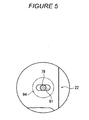
Figure 5 is an enlarged view showing a part ofFigure 4 enclosed by a chain line. -
Figure 6 is a side view showing that the back member is positioned at a second end of the stroke range. -
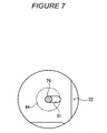
Figure 7 is an enlarged view showing a part ofFigure 6 enclosed by a chain line. -
Figure 8 is a side view illustrating an operation of changing the gauge between a middle roller and a third roller. -
Figure 9 is a side view illustrating an operation of removing the back menber of the side plate for replacement. -
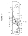
Figure 10 is a side view illustrating an operation of mounting a new back member. - A preferred embodiment of the present invention will be described below with reference to the drawings.
Figure 1 shows a spinning machine 1 serving as a textile machine and comprising a large number of juxtaposed spinning units (yarn processing units) 2. - As shown in
Figure 1 , each of thespinning units 2 has adraft device 7, aspinning device 9, ayarn feeding device 11, and a windingdevice 12 as main components. Thespinning unit 2 is configured such that thedraft device 7 is provided near an upper end of a casing 6 of the spinning machine 1 main body so that afiber bundle 8 fed from thedraft device 7 is spun by thespinning device 9. A spunyarn 10 discharged by thespinning device 9 is fed downward by theyarn feeding device 11. The spunyarn 10 then passes through a clearer (yarn defect detector) 52 which detects a defect in the yarn and which cuts the defective yarn to remove the defective yarn part. The spunyarn 10 is then wound by the windingdevice 12 to form apackage 45. - The spinning machine 1 is equipped with a
blower box 80 and amotor box 81. Furthermore, although not shown in the figure, the spinning machine 1 comprise a yarn splicing vehicle provided so as to travelable in a direction in which thespinning units 2 are arranged and a doffing vehicle provided so as to be travelable independently of the yarn splicing vehicle. -
Figure 2 shows an enlarged side view of thedraft device 7, thespinning device 9, and theyarn feeding device 11. Thedraft device 7 comprises a draft roller that draws asliver 13 into afiber bundle 8. The draft roller is composed of a top roller and a bottom roller arranged opposite each other. - The top roller is composed of four rollers, that is, a
back roller 14, athird roller 15, amiddle roller 16 around which anapron belt 17 is installed, and afront roller 18. Thesetop rollers like cradle 20 provided in thedraft device 7. On the other hand, a bottom roller is composed of four rollers, aback bottom roller 24, a thirdbottom roller 25, amiddle roller 26 around which anapron belt 27 is installed, and afront bottom roller 28. Thebottom rollers draft device 7 main body and arranged opposite thetop rollers - A spring box (not shown in the drawings) is provided inside the
cradle 20 to bias thetop rollers top rollers bottom rollers sliver 13 to be nipped between thetop rollers bottom rollers - The respective
top rollers side plate 70 mounted to a side surface of thecradle 20. This sets the distances (gauges) between the nip points of thetop rollers cradles 20 is provided for twospinning units 2 as shown inFigure 2 , and theside plate 70 is mounted to each of the opposite surfaces of thecradle 20. The details of the configuration of theside plate 70 will be described below. - In the above-described configuration, the
sliver 13 fed to thedraft device 7 is drawn by the draft rollers, rotationally driven at different speeds, and is thus formed into thefiber bundle 8, which is then fed to thespinning device 9, as shown inFigure 2 . Thespinning device 9 pneumatically spins thefiber bundle 8 fed from thedraft device 7. The pneumatically spunfiber bundle 8 is fed to theyarn feeding device 11 as the spunyarn 10. - The
yarn feeding device 11 comprises adelivery roller 39 supported by the casing of the spinning machine 1 main body and anip roller 40 provided so as to freely contact and leave thedelivery roller 39. In this configuration, the spunyarn 10 discharged by thespinning device 9 is sandwiched between thedelivery roller 39 and thenip roller 40, and thedelivery roller 39 is then rotationally driven. The spunyarn 10 can thus be fed to the windingdevice 12. - The
cradle 20 is provided so as to be pivotable around a pivotingshaft portion 29 with respect to thedraft device 7. Furthermore, acradle handle 23 is fixed to thecradle 20. In this configuration, while the spinning machine 1 is in operation, thecradle 20 is in the position shown inFigure 2 and is locked by a lock mechanism (not shown in the drawings). Thecradle 20 is opened by unlocking the lock mechanism and raising thecradle handle 23. In this condition, the following operations are performed: a maintenance operation including replacement of thetop roller bottom roller - Now, the
side plate 70, mounted to thecradle 20, will be described.Figure 3 shows a diagram of theentire side plate 70 according to one embodiment of the present invention. As shown inFigure 3 , theside plate 70 is divided into a front member (fixed member) 21 and a back member (movable member) 22. Each of thefront member 21 and theback member 22 is made of metal and formed like a plate having a predetermined thickness. - The
front member 21 comprises a frontroller support portion 78 that supports thefront roller 18 and a middleroller support portion 76 that supports themiddle roller 16. Furthermore, theback member 22 comprises a thirdroller support portion 75 that supports thethird roller 15 and a backroller support portion 74 that supports theback roller 14. Theroller support portions top rollers top rollers - The front
roller support portion 78 and the middleroller support portion 76 are both formed in thefront member 21. Consequently, the gauge between thefront roller 18 and themiddle roller 16 is unchangeable. Similarly, the thirdroller support portion 75 and theroller support portion 74 are both formed in theback member 22. Consequently, the gauge between thethird roller 15 and theback roller 14 is unchangeable. - The positions of the
roller support portions front roller 18 and themiddle roller 16, and the gauge between thethird roller 15 and theback roller 14 are set equal to preset predetermined distances. However, plural types ofback member 22 are manufactured and prepared which have different gauges between thethird roller 15 and theback roller 14. - Circular penetrating mounting
holes front member 21 of theside plate 70. Thefront member 21 is mounted to thecradle 20 by threadably insertingscrews holes 69, 69 (seeFigure 4 ). The threadable insertion of the screws immovably fixes theside plate 70 to thecradle 20. Consequently, the frontroller support portion 78 and the middleroller support portion 76 are fixed and the positions thereof are unchangeable. - As shown in
Figure 3 , anotch portion 63 and aslot portion 61 are formed in theback member 22 of theside plate 70. Thenotch portion 63 and theslot portion 61 are formed to be elongate along a direction in which theroller support portions sliver 13 travels). Thenotch portion 63 is shaped like a slot that is open at one end thereof which is closer to thefront member 21. Furthermore, theslot portion 61 is located at an end of theback member 22 which is farther from thefront member 21. - The
back member 22 is fixed to thecradle 20 by threadably insertingscrews notch portion 63 and the slot portion 61 (seeFigure 4 ). Furthermore, as shown inFigure 3 , theback member 22 comprises an abuttingportion 62 having a surface (abutting surface) that can be contacted with an end surface of thefront member 21. - The
cradle 20 has internally threaded holes formed therein and into which thescrews 91 to 94 are threadably inserted. An inner portion of thecradle 20 is padded at the positions of the internally threaded holes by welding or the like to so as to offer an appropriate strength. - The
back member 22 can be moved within a predetermined stroke range along thenotch portion 63 and theslot portion 61 by loosening thescrews 93, 94 (Figure 4 ) for mounting. This means that the gauge between themiddle roller 16 and thethird roller 15 can be changed with the gauge between thefront roller 18 and themiddle roller 16, and the gauge between thethird roller 15 and theback roller 14 maintained constant. - As the
back member 22 is moved closer to thefront member 21, the abutting surface of the abuttingportion 62 comes into contact with thefront member 21 to prevent theback member 22 from moving further toward thefront member 21 side as shown inFigure 4 . This defines a first end of the stroke range of theback member 22. In this condition, as shown inFigure 5 that is an enlarged view of a part ofFigure 4 enclosed by a chain line, ashaft potion 79 of thescrew 94 inserted through theslot portion 61 is positioned in the middle of theslot portion 61 in a longitudinal direction thereof. - The position of the
roller support portions portion 62, and the like are set such that in the condition inFigure 4 , in which theback member 22 is positioned at the first end of the stroke range, a preset first pitch (gauge) P1 is provided between themiddle roller 16 and thethird roller 15. - On the other hand, as the
back member 22 is moved away from thefront member 21 and when a condition shown inFigure 6 is established, theshaft portion 79 of thescrew 94 comes into contact with one end of the slot portion 61 (seeFigure 7 that is an enlarged view of a part ofFigure 6 which is enclosed by a chain line). This inhibits theback member 22 from moving away from thefront member 21 to define a second end of the stoke range of theback member 22. - The positions of the
roller support portions slot portion 61, thescrew 94, and the like are set such that in the condition inFigure 6 , in which theback member 22 is positioned at the second end of the stroke range, a preset second pitch (gauge) P2 is provided between themiddle roller 16 and thethird roller 15. Furthermore, the second pitch P2 is set larger than the first pitch P1 (Figure 4 ) provided when theback member 22 is positioned at the opposite end of the stroke range. - Thus, by performing a simple operation of moving and positioning the
back member 22 at the first end or second end of the stroke range and then tightening the screw, it is possible to obtain the preset first pitch P1 or preset second pitch P2 as the gauge between themiddle roller 16 and thethird roller 15. In particular, since the two pitches P1, P2 are set at the first end and second end of the stroke range, it is unnecessary to perform a complicated operation of precisely adjusting the position of theback member 22 in the middle of the stroke range. Furthermore, desired pitches can be reproductively obtained. - As shown in
Figure 3 , thefront member 21 has a protrudingportion 71 protruding toward theback member 22 and theback member 22 has a recess portion formed at a position corresponding to the protrudingportion 71. The protrudingportion 71 of thefront member 21 comprises areference line 64 as a reference display portion. On the other hand, theback member 22 comprises along gauge line 65 and ashort gauge line 67 located beside the recess portion and serving as position display portions. A longgauge display portion 66 and a shortgauge display portion 68 are provided close to thelong gauge line 65 and theshort gauge line 67, respectively. Thedisplay portions middle roller 16 and the third roller 15 (first pitch P1 and second pitch P2), for example, as numerical values in millimeters. - The positions of the
reference line 64, thelong gauge line 65, and theshort gauge line 67 are set such that moving theback member 22 to the first end of the stroke range aligns thereference line 64 with theshort gauge line 67 as shown inFigure 4 , whereas moving theback member 22 to the second end of the stroke range aligns thereference line 64 with thelong gauge line 65 as shown inFigure 6 . Thus, reading the positional relationship between thereference line 64 and the twogauge lines back member 22 is positioned at the appropriate end of the stroke range. - An operation of changing the gauge between the
middle roller 16 and thethird roller 15 is performed as described below. That is, with thecradle 20 open as shown inFigure 8 , a tool is used to loosen thescrews back member 22. Theback member 22 is then moved from the first end to second end of the stroke range. Thescrews middle bottom roller 26 and the thirdbottom roller 25 shown inFigure 2 is also appropriately performed with thecradle 20 open. Subsequently, thecradle 20 is closed to complete the pitch changing operation. - The pitch changing operation can be performed with the
top rollers roller support portions side plate 70 as shown inFigure 8 . This eliminates the need for an operation of removing and then mounting thetop rollers - When the
back member 22 is moved, thethird roller 15 and theback roller 14 move simultaneously with theback member 22. Thus, a position on which the bias force of the spring box, provided in thecradle 20, acts is pre-adjusted such that an appropriate bias force can be exerted even though thethird roller 15 or theback roller 14 moves. - On the other hand, changing the pitch between the
third roller 15 and theback roller 14 requires replacement of theback member 22 and is thus performed as described below. - That is, first, with the
cradle 20 open, thethird roller 15 and the back roller 14 (seeFigure 2 ) are removed from theroller support portions back member 22. Then, a tool is used to appropriately loosen the screw 93 (seeFigure 4 ) locking theback member 22 at thenotch portion 63. Furthermore, thescrew 94 locking theback member 22 at theslot portion 61 is removed. - Then, in the condition shown in
Figure 9 , theback member 22 is pulled out and away from thefront member 21 as shown the arrow. Then, the shaft portion of thescrew 93 is pulled out from the open end of thenotch portion 63. Thus, with thescrew 93 remaining attached to thecradle 20, theback member 22 can be easily removed from thecradle 20. - Then, as shown in
Figure 10 , aback member 22X in which the gauge between thethird roller 15 and theback roller 14 is different from that in the removed backmember 22 is set such that the shaft portion of thescrew 93 is inserted into thenotch portion 63. Thescrew 94 is inserted into theslot portion 61 again. Then, with thescrews back member 22X is positioned at the first end or second end of the stroke range. Subsequently, thescrews back member 22X to thecradle 20. - As shown in
Figures 9 and10 , this pitch changing operation does not require the replacement of thefront member 21 and can be performed with thetop rollers front member 21 side held in theroller support portions - For example, various mechanisms such as a cleaner which are used to clean the surfaces of the
top rollers screw 93. Thus, a work space for the attachment/removal of thescrew 93 often fails to be provided. In this connection, the back member 22 (22X) according to the present embodiment comprises the slot-like notch portion 63 with the open portion. Thus, simply by inserting a tool such as a driver into a thread groove in a head portion of thescrew 93 to loosen thescrew 93, the shaft portion of thescrew 93 can be inserted into or removed from thenotch portion 63 via the open portion without completely removing thescrew 93 from thecradle 20. Therefore, theback member 22 can be easily replaced with a different one. - As shown above, in the
draft device 7 according to the present embodiment, theside plate 70, used to position the plurality of draft rollers (top rollers side plate 70 is divided into thefront member 21 as a fixed member, which is mounted to thedraft device 7 at a fixed position, and theback member 22 as a movable member, the position of which with respect to thedraft device 7 is changeable within a predetermined stroke range. Thefront member 21 comprises the frontroller support portion 78 and the middleroller support portion 76. Furthermore, theback member 22 comprises the thirdroller support portion 75 and theroller support portion 74. When theback member 22 is positioned at the first end of the stroke range (Figure 4 ), the preset first pitch P1 is provided between themiddle roller 16 on thefront member 21 side and thethird roller 15 on theback member 22 side. When theback member 22 is positioned at the second end of the stroke range (Figure 6 ), the preset second pitch P1, which is different from the first pitch P1, is provided between themiddle roller 16 on thefront member 21 side and thethird roller 15 on theback member 22 side. - With this configuration, the gauge between the
middle roller 16 and thethird roller 15 can be easily changed by changing the mounting position of theback member 22 between the first end and second end of the stroke range. Furthermore, the first pitch P1 or the second pitch P2 can be accurately provided by positioning theback member 22 at the first end or second end of the stroke range. Thus, the operation of precisely adjusting the position of theback member 22 need not be performed. This also facilitates the gauge changing operation. Furthermore, as shown inFigure 8 , the gauge can be adjusted without the need to remove thetop rollers side plate 70. Therefore, the effort and time required for the gauge changing operation can be reduced. - Furthermore, in the
side plate 70 according to the present embodiment, theback member 22 comprises the thirdroller support portion 75 and the backroller support portion 74. Theside plate 70 is configured such that moving theback member 22 integrally moves the thirdroller support portion 75 and the backroller support portion 74. - With this configuration, simply moving the
back member 22 enables the gauge between themiddle roller 16 and thethird roller 15 to be easily changed while maintaining the gauge between thethird roller 15 and theback roller 14. This allows the efficiency of the gauge changing operation to be improved. - Furthermore, the side plate according to the present embodiment is configured such that with the
front member 21 fixed to thedraft device 7, theback member 22 is replaceable with thedifferent back member 22X with the roller support portions arranged at a distance from each other which is different from the distance between the roller support portions of theback member 22. - With this configuration, to change the gauge between the
third roller 15 and theback roller 14, it is only necessary to replace theback member 22 with a different one with thefront member 21 remaining fixed to thedraft device 7. Furthermore, theback member 22 can be replaced with a different one with thefront roller 18 and themiddle roller 16 held on thefront member 21 side. Consequently, the gauge changing operation can be efficiently performed. Moreover, the gauge can be changed to any of various values simply by moving and replacing the back member with a different one with thefront member 21 remaining unchanged. This enables a reduction in the material costs of theside plate 70 and in manufacturing costs such as the production costs of die assembly. - Furthermore, in the present embodiment, the
back member 22 comprises the abutting surface on the abuttingportion 62. The abutting surface contacts with thefront member 21 as shown inFigure 4 to position theback member 22 at the appropriate end of the stroke range. - Thus, the first pitch P1 can be reproducively obtained using the simple configuration.
- Furthermore, in the present embodiment, the
slot portion 61 is formed in theback member 22, and the end of theslot portion 61 is used to position theback member 22 at the appropriate end of the stroke range as shown inFigures 6 and7 . - Thus, the second pitch P2 can be reproducively obtained using the simple configuration.
- Furthermore, in the present embodiment, the
back member 22 comprises thenotch portion 63 as a slot having one open end, and theback member 22 is mounted to thecradle 20 with the shaft portion of thescrew 93 inserted through thenotch portion 63. - With this configuration, to be replaced with a different one, the
back member 22 can be removed from thedraft device 7 without thescrew 93 remaining threadably inserted into thedraft device 9. Consequently, the operation of attaching/removing thescrew 93 can be omitted, facilitating the operation of replacing theback member 22 with a different one. - Furthermore, in the present embodiment, the
front member 21 comprises thereference line 64, and theback member 22 comprises the twogauge lines - As shown in
Figures 4 and6 , when theback member 22 is positioned at one of the opposite ends of the stroke range, thereference line 64 aligns with one of the twogauge lines - With this configuration, reading the
reference line 64 and the gauge lines 65, 67 makes it possible to easily determine whether or not theback member 22 is reliably positioned at the appropriate end of the stroke end. - Furthermore, in the present embodiment, in the
back member 22, thedisplay portions respective gauge lines display portions - This configuration makes it possible to easily determine the gauge between the
middle roller 16 and thethird roller 15. - The preferred embodiment of the present invention has been described above. However, the present invention can be varied, for example, as described below.
- The present invention is not limited to the case where the
back member 22 is mounted directly to thedraft device 7. For example, theback member 22 can be mounted to thefront member 21 fixed to thedraft device 7 so that theback member 22 is movable within the predetermined stroke range. - The
back member 22 according to the present embodiment is configured to be positioned by the appropriate end of the penetratingslot portion 61. However, the present invention is not limited to this. Theback menber 22 can be positioned by, for example, forming a non-penetrating recess in a surface of theback member 22 which faces thedraft device 7, and inserting a pin projecting from the draft device into the groove so that the pin abuts against an appropriate end of the groove. - Alternatively, the
back member 22 can be positioned by inserting a pin projecting from theback member 22 into a slot or groove formed in thefront member 21 so that the pin comes into contact with an appropriate end of the slot or groove. - Instead of the
linear reference line 64 andgauge lines - The
side plate 70 according to the above-described embodiment is applicable not only to the four-line type draft device but also to a five-line type draft device or a draft device based on any other scheme. - While the present invention has been described with respect to preferred embodiments thereof, it will be apparent to those skilled in the art that the disclosed invention may be modified in numerous ways and may assume many embodiments other than those specifically set out and described above. Accordingly, the appended claims cover the scope of the invention.
Claims (8)
- A side plate (70) used to position a plurality of top draft rollers (14, 15, 16, 18) associated with bottom draft rollers (24, 25, 26, 28) in a draft device (7) comprising
a fixed roller support member (21) fixed to the draft device (7), and
a moveable roller support member (22), the position of which is variable within a predetermined stroke with respect to the draft device (7),
characterized in that
the moveable roller support member (22) comprises a plurality of roller support portions (74, 75) so that when the moveable roller support member (22) is positioned at a first or second end of the stroke a preset first or second pitch is provided between the draft rollers (14, 15, 16, 18) on the fixed and the moveable roller support member (21, 22). - The side plate (70) according to claim 1,
characterized in that
the movable roller support member (22) is replaceable with another movable roller support member having roller support portions arranged at a different distance. - The side plate (70) according to claim 1 or 2,
characterized in that
the movable roller support member (22) has an abutting portion (62) that contacts the fixed roller support portion (21) when the movable roller support portion (22) is at the first end of the stroke. - The side plate (70) according to one of the claims 1 to 3,
characterized in that
a slot (61) is formed in at least the fixed roller support member (21) or the movable roller support member (22), and an end of the slot is used to position the movable roller support member (22) at the second end of the stroke. - The side plate (70) according to one of the claims 1 to 4,
characterized in that
the movable roller support member (22) comprises a slot (63) having an open end, and the movable roller support member (22) is mounted to the draft device (7) with a shaft portion of a mounting member (93) inserted through the slot. - The side plate (70) according to one of the claims 1 to 5,
characterized in that
the fixed roller support member (21) comprises a reference display line (64), the moveable roller support member (22) comprises two position display lines (65, 67), and the reference display line aligns with one of the two position display lines when the moveable roller support member is positioned at one end of the stroke. - A draft device (7) comprising the side plate (70) according to one of the claims 1 to 6.
- A textile machine comprising a draft device (7) according to claim 7.
Applications Claiming Priority (1)
| Application Number | Priority Date | Filing Date | Title |
|---|---|---|---|
| JP2007162645A JP2009001928A (en) | 2007-06-20 | 2007-06-20 | Side plate, drafting device, and textile machine |
Publications (2)
| Publication Number | Publication Date |
|---|---|
| EP2006426A1 EP2006426A1 (en) | 2008-12-24 |
| EP2006426B1 true EP2006426B1 (en) | 2009-12-23 |
Family
ID=39952256
Family Applications (1)
| Application Number | Title | Priority Date | Filing Date |
|---|---|---|---|
| EP20080010067 Not-in-force EP2006426B1 (en) | 2007-06-20 | 2008-06-02 | Side plate for drafting device |
Country Status (4)
| Country | Link |
|---|---|
| EP (1) | EP2006426B1 (en) |
| JP (1) | JP2009001928A (en) |
| CN (1) | CN101328629B (en) |
| DE (1) | DE602008000434D1 (en) |
Families Citing this family (3)
| Publication number | Priority date | Publication date | Assignee | Title |
|---|---|---|---|---|
| JP5516050B2 (en) * | 2010-05-12 | 2014-06-11 | 株式会社豊田自動織機 | Spinning machine drafting equipment |
| JP5677259B2 (en) * | 2011-09-28 | 2015-02-25 | 富士通周辺機株式会社 | Keystroke device |
| CN102828290A (en) * | 2012-09-18 | 2012-12-19 | 宋继刚 | Spinning machine bottom pin space gauge and method for adjusting spinning machine bottom pin space |
Family Cites Families (5)
| Publication number | Priority date | Publication date | Assignee | Title |
|---|---|---|---|---|
| GB190923392A (en) * | 1909-10-13 | 1910-10-13 | John Owden O'brien | Improvements in Underclearers for the Drawing-rollers of Drawing, Slubbing, Intermediate and Roving Frames and similar Machines for Preparing Cotton, Flax, Wool or other Fibres for Spinning. |
| JPH04123268U (en) | 1991-04-18 | 1992-11-06 | 村田機械株式会社 | Gauge adjustment mechanism in draft equipment |
| DE4205854A1 (en) * | 1992-02-26 | 1993-09-02 | Stahlecker Fritz | TEXTILE MACHINE WITH A VARIETY OF STRETCHING DEVICES ARRANGED IN ADJUSTMENT |
| DE4318025A1 (en) * | 1992-10-20 | 1994-04-21 | Stahlecker Fritz | Bearing support for lower rolls of spinning machine drafting systems - comprises steel pressings which form slot to accept bearing block projections |
| EP1609894A1 (en) * | 2004-06-26 | 2005-12-28 | Maschinenfabrik Rieter Ag | Device for adjusting the length of the draft zone |
-
2007
- 2007-06-20 JP JP2007162645A patent/JP2009001928A/en active Pending
-
2008
- 2008-05-21 CN CN2008100993288A patent/CN101328629B/en active Active
- 2008-06-02 DE DE200860000434 patent/DE602008000434D1/en active Active
- 2008-06-02 EP EP20080010067 patent/EP2006426B1/en not_active Not-in-force
Also Published As
| Publication number | Publication date |
|---|---|
| JP2009001928A (en) | 2009-01-08 |
| CN101328629B (en) | 2012-01-18 |
| CN101328629A (en) | 2008-12-24 |
| DE602008000434D1 (en) | 2010-02-04 |
| EP2006426A1 (en) | 2008-12-24 |
Similar Documents
| Publication | Publication Date | Title |
|---|---|---|
| EP2006426B1 (en) | Side plate for drafting device | |
| EP2567922B1 (en) | Waxing device, spinning unit, and spinning machine | |
| EP1188850A2 (en) | Open-end spinning device | |
| EP2460916A2 (en) | Draft device in prespinning process | |
| EP2072647B1 (en) | Draft roller | |
| CN108977945B (en) | Roller unit, draft device, and spinning machine | |
| CZ281437B6 (en) | Spinning apparatus for spindleless spinning | |
| US2707309A (en) | Draw box roll setting mechanism | |
| JP2008530382A (en) | Lower apron guide device for double apron draft device | |
| US5809762A (en) | Draw frame with adjustment device for the drafting rollers | |
| CN217973536U (en) | Draft device, air jet spinning machine, side plate for draft device, and spring box | |
| CN220283109U (en) | Spandex doubling winder | |
| US2941263A (en) | Textile drawing mechanism | |
| US8341807B2 (en) | Mounting device for producing an all-steel card clothing | |
| CN112626684B (en) | Guide cutting device for textile coil machine | |
| JPH04241156A (en) | Warp knitting machine provided with jacquard guide bar | |
| CN220555732U (en) | Automatic feeding device of roving frame | |
| CN109423717B (en) | Drafting device of spinning machine | |
| CN107964721B (en) | Warp yarn feeding device in loom | |
| CN106637538B (en) | Cotton passing plate of multi-fiber comber | |
| US2704863A (en) | Textile drafting machines | |
| CN101115872A (en) | Bottom apron guide for double-apron draft system | |
| JP2023024347A (en) | Draft system, and method for loading and opening draft system | |
| EP3647475A1 (en) | Drafting assembly for a ring spinning machine and drafting kit for drafting fibres on a ring spinning machine | |
| CN106987935B (en) | Tension device, drafting device and spinning machine |
Legal Events
| Date | Code | Title | Description |
|---|---|---|---|
| PUAI | Public reference made under article 153(3) epc to a published international application that has entered the european phase |
Free format text: ORIGINAL CODE: 0009012 |
|
| AK | Designated contracting states |
Kind code of ref document: A1 Designated state(s): AT BE BG CH CY CZ DE DK EE ES FI FR GB GR HR HU IE IS IT LI LT LU LV MC MT NL NO PL PT RO SE SI SK TR |
|
| AX | Request for extension of the european patent |
Extension state: AL BA MK RS |
|
| 17P | Request for examination filed |
Effective date: 20090409 |
|
| GRAP | Despatch of communication of intention to grant a patent |
Free format text: ORIGINAL CODE: EPIDOSNIGR1 |
|
| AKX | Designation fees paid |
Designated state(s): CH DE LI |
|
| GRAS | Grant fee paid |
Free format text: ORIGINAL CODE: EPIDOSNIGR3 |
|
| GRAA | (expected) grant |
Free format text: ORIGINAL CODE: 0009210 |
|
| AK | Designated contracting states |
Kind code of ref document: B1 Designated state(s): CH DE LI |
|
| REG | Reference to a national code |
Ref country code: CH Ref legal event code: EP |
|
| REF | Corresponds to: |
Ref document number: 602008000434 Country of ref document: DE Date of ref document: 20100204 Kind code of ref document: P |
|
| PLBE | No opposition filed within time limit |
Free format text: ORIGINAL CODE: 0009261 |
|
| STAA | Information on the status of an ep patent application or granted ep patent |
Free format text: STATUS: NO OPPOSITION FILED WITHIN TIME LIMIT |
|
| 26N | No opposition filed |
Effective date: 20100924 |
|
| PGFP | Annual fee paid to national office [announced via postgrant information from national office to epo] |
Ref country code: CH Payment date: 20120622 Year of fee payment: 5 Ref country code: DE Payment date: 20120622 Year of fee payment: 5 |
|
| REG | Reference to a national code |
Ref country code: CH Ref legal event code: PL |
|
| REG | Reference to a national code |
Ref country code: DE Ref legal event code: R119 Ref document number: 602008000434 Country of ref document: DE Effective date: 20140101 |
|
| PG25 | Lapsed in a contracting state [announced via postgrant information from national office to epo] |
Ref country code: CH Free format text: LAPSE BECAUSE OF NON-PAYMENT OF DUE FEES Effective date: 20130630 Ref country code: LI Free format text: LAPSE BECAUSE OF NON-PAYMENT OF DUE FEES Effective date: 20130630 Ref country code: DE Free format text: LAPSE BECAUSE OF NON-PAYMENT OF DUE FEES Effective date: 20140101 |