EP2130577A1 - Luftaufbereitungsvorrichtung, insbesondere einer Luftdruckbremsanlage mit einem Abscheider für flüssige Fluide - Google Patents
Luftaufbereitungsvorrichtung, insbesondere einer Luftdruckbremsanlage mit einem Abscheider für flüssige Fluide Download PDFInfo
- Publication number
- EP2130577A1 EP2130577A1 EP09161224A EP09161224A EP2130577A1 EP 2130577 A1 EP2130577 A1 EP 2130577A1 EP 09161224 A EP09161224 A EP 09161224A EP 09161224 A EP09161224 A EP 09161224A EP 2130577 A1 EP2130577 A1 EP 2130577A1
- Authority
- EP
- European Patent Office
- Prior art keywords
- air
- treatment device
- housing
- air treatment
- separation channel
- Prior art date
- Legal status (The legal status is an assumption and is not a legal conclusion. Google has not performed a legal analysis and makes no representation as to the accuracy of the status listed.)
- Granted
Links
Images


Classifications
-
- B—PERFORMING OPERATIONS; TRANSPORTING
- B60—VEHICLES IN GENERAL
- B60T—VEHICLE BRAKE CONTROL SYSTEMS OR PARTS THEREOF; BRAKE CONTROL SYSTEMS OR PARTS THEREOF, IN GENERAL; ARRANGEMENT OF BRAKING ELEMENTS ON VEHICLES IN GENERAL; PORTABLE DEVICES FOR PREVENTING UNWANTED MOVEMENT OF VEHICLES; VEHICLE MODIFICATIONS TO FACILITATE COOLING OF BRAKES
- B60T17/00—Component parts, details, or accessories of power brake systems not covered by groups B60T8/00, B60T13/00 or B60T15/00, or presenting other characteristic features
- B60T17/002—Air treatment devices
- B60T17/004—Draining and drying devices
-
- B—PERFORMING OPERATIONS; TRANSPORTING
- B01—PHYSICAL OR CHEMICAL PROCESSES OR APPARATUS IN GENERAL
- B01D—SEPARATION
- B01D2257/00—Components to be removed
- B01D2257/80—Water
Definitions
- the invention relates to an air treatment device, in particular an air pressure brake system with a separator for liquid fluids, in particular oil or water, which has a substantially cylindrical housing, which has at its end faces a housing cover and a housing bottom, and having in its interior a separation channel, the the air to be cleaned can flow through, wherein the separation channel is curved in the circumferential direction of the housing and has at least one inlet opening for the air to be cleaned, at least one fluid outlet opening for separated fluid and at least one clean air outlet opening for purified air. Furthermore, the invention relates to a separator for liquid fluid for such an air treatment device.
- Such known air treatment devices are preferably used to dehumidify the compressed air supplied by a compressor before it is supplied to a compressed air consumer, in particular an air pressure brake system.
- the supplied from the compressor compressed air is particularly dirty with oil used in the compressor as a lubricant; For example, further pollution comes from the atmosphere. It is known to remove such and other contaminants To use a so-called oil separator, which must flow through the compressed air.
- an air conditioning apparatus with an oil separator having a first space and a second space is known.
- the spaces are designed as substantially axially symmetrical annular spaces with a common axis.
- compressed air can be introduced.
- air guiding means are arranged, can be changed by the flow velocity of the air flowing through.
- the air purified in the first space can be fed to the second space and from there to a filter unit.
- a plurality of complex shaped components is required, which must be interconnected.
- the invention has for its object to design an air treatment device and a separator for an air treatment device, which are easy to implement with as few components and allow optimal separation of liquid fluids.
- This object is achieved in that the separation channel downstream of the fluid outlet opening has a spoiler for guiding the clean air to the clean air outlet opening.
- an air-guiding ramp which can be realized simply by, for example, corresponding shaping of the housing bottom or the housing cover and with which the clean air is conducted to the clean-air outlet opening.
- the inclination of the ramp prevents that already separated liquid is carried along, as it settles due to the inertia at the foot of the air guide ramp.
- the separator can be assembled from a total of only two components by the Abscheidekanal is simply limited by the housing walls, the housing cover and the housing bottom.
- the housing and the housing cover can be poured easily from plastic, for example, via an injection molding process.
- the housing cover can be easily connected to the housing by means of ultrasonic welding or gluing.
- the separation channel can be roughly spiral, helical or circular.
- an efficient separation of liquid fluid in particular of oil, fuel and / or water can be realized.
- the fluid particles are driven off due to their greater mass than air by the centrifugal force when flowing through the Abscheidekanals to the outside wall and remain there first compressed to form a film, and then descend the gravitational force on the housing bottom.
- the at least one inlet opening can be arranged from outside the housing easily accessible in a radially outer wall of the separation channel.
- the inside of the radially outer wall of the separation channel may have at least a portion of reduced radius. Due to the reduced radius, the separation efficiency of the radially outwardly flowing liquid particles on the wall of the separation channel increases. Moreover, if only the radius of the radially outer wall is reduced, a narrowing of the separation channel can easily be achieved in which the flow velocity is changed. This also has a positive effect on the separation efficiency. Subsequent to the reduced radius section, the separation channel may expand again, thereby calming the airflow, which also has a beneficial effect on the separation efficiency.
- At least one baffle can be arranged in the separation channel, which has a surface component perpendicular to the flow path.
- the inert liquid droplets bounce against the baffle wall as they flow through the separation channel, where they initially adhere as a film and then sink to the base of the housing.
- At least two baffles can be arranged in a labyrinth-like offset from one another.
- the housing cover may have on its outer side facing away from the Abscheidekanal a structure which extends at least in the region of Lucasleitrampe along the Abscheidekanals and is open to the Abscheidekanal, wherein in a radially inner and / or a radially outer side wall of the structure at least one clean air outlet opening is arranged.
- the clean air can flow in the axial direction of the separation channel.
- the arrangement of the clean air outlet opening in a side wall of the structure also has the advantage that a further diversion of the flow from the separation channel is realized by the clean air outlet opening, whereby an additional Abscheideitzkeit is created.
- the direct view into the separation channel is prevented by the lateral arrangement of the clean air outlet opening, so that emulsion and particulate dirt and soot residues viewed from outside the separator remain visually largely concealed.
- a plurality of clean air outlet openings may be arranged in the radially inner and / or the radially outer side wall of the structure. In this way, the exit area is increased, whereby a backwater of the clean air is avoided.
- the flow cross sections of the clean air outlet openings further away from the air guide ramp can advantageously be larger than the flow cross sections of the nearer clean air outlet openings.
- At least one fluid outlet opening can be arranged in the housing bottom.
- the housing bottom points spatially downward, so easily the separated fluid can flow through the fluid outlet opening down from the separation channel.
- the housing bottom can advantageously run downhill in the installed state of the separator towards the fluid outlet opening.
- FIG. 1 is an overall provided with the reference numeral 10 air treatment device of an air pressure brake system, not shown otherwise.
- the air treatment device 10 comprises in the FIG. 1 above a separator 12 for liquid fluids, such as oil and water, from the compressed air to be processed.
- the separator 12 is inserted from above in an air dryer housing 13.
- the separator 12 is made of plastic. He assigns to the FIGS. 2 to 5 shown cylindrical housing lower part 14 and a in the FIGS. 1 and 2 shown housing cover 16.
- the lower housing part 14 has an outer wall 18 and a likewise cylindrical inner wall 20, which is coaxial therewith.
- the outer wall 18, the inner wall 20, the housing cover 16 and a housing bottom 21 define a separation channel 23, which can flow through the air to be purified from the housing cover 16 in a clockwise direction.
- the separation channel 23 has four sections, namely, viewed in the flow direction, an inlet section 23a, a baffle section 23b, a fluid outlet section 23c and an air ramp section 23d.
- the inlet section 23a, the baffle section 23b and the fluid outlet section 23c each extend along the flow path approximately over one third of the circumference of the housing bottom part 14.
- the air ramp section 23d runs parallel to the inlet section 23a and adjoins the radially inner side thereof by an intermediate wall 25 of the latter ,
- the intermediate wall 25 extends from the housing bottom 21 to the housing cover 16. It is integrally formed on the housing bottom 21 and sealed relative to the housing cover 16.
- the axial distance of the housing bottom 21 from the housing cover 16 increases in the main flow direction to, so that the housing bottom 21 in the installed state, in which the housing axis is vertical, a gradient, whereby the separated fluid can drain better.
- the housing bottom 21 facing edge of the outer wall 18 terminates with the housing bottom 21.
- the lower edge of the inner wall 20 closes where it abuts the housing bottom 21, with this.
- unnecessary voids are avoided, whereby the manufacturing process of the housing base 14 is simplified.
- the upper, the housing cover 16 facing edges of the outer wall 18 and the inner wall 20 are flat.
- an inlet opening 27 for air to be cleaned is arranged in the outer wall 18.
- the housing bottom 21 of the housing cover 16 closest, so that in the installed state there is the highest position of the housing bottom 21.
- Downstream of the inlet opening 27 just before the end of the inlet section 23a is located in the outer wall 18 in the FIG. 5 shown secondary inlet opening 29, via which in a manner not further interesting way recycled air, such as a leakage air flow, can be supplied.
- recycled air such as a leakage air flow
- the outer wall 18 has a radially inwardly bent section part 31.
- a first baffle 33 is formed at the radially innermost point of the section part 31, which has a reduced compared to the inlet portion 23 a radius.
- the first baffle 33 extends in the radial direction and in the axial direction, that is, has a surface component perpendicular to the main flow path.
- the two baffles 33 and 35 realize together with the section portion 31 a labyrinthine flow path in which the liquid fluids due to their inertia against the outer wall 18 and against the baffles 33 and 35 bounce and stick there as a film first, and then fall by gravity to the housing bottom 21.
- the outer wall 18 Downstream of the section part 31, the outer wall 18 has a straight section part 37, which represents a secant of the inner contour of the outer wall 18 which does not intersect the housing axis.
- the straight portion portion 37 realizes a cross-sectional reduction of the separation channel 23 and an oblique impact surface for the fluids.
- the outer wall 18 On the flow path shortly before the end of the impingement separating section, the outer wall 18 has a further elevation 39 formed radially inward, which leads to a further reduction in cross-section of the separating channel 23.
- a baffle plate 43 is integrally formed at the bottom of the housing bottom 21, which extends axially and approximately radially to the housing axis perpendicular to the main flow direction.
- the air outlet section 23c is adjoined by the air ramp section 23d.
- the housing bottom 21 is approximately at the same axial height as at the beginning of the inlet section 23a.
- the axial distance of the housing bottom 21 to the housing cover 16 decreases continuously; the rising housing bottom 21 thus forms an air-guiding ramp 45.
- the air ramp section 23d extends in a region between the fluid outlet opening 41 and a section of the intermediate wall 25 extending radially to the housing axis, which also forms the boundary at the beginning of the inlet section 23a and acts as a further radially outwardly located impact surface, extends the air ramp section 23d in the radial direction over the entire extent between the outer wall 18 and the inner wall 20.
- the outer wall 18 has a further opening 47 to which, for example, a pressure sensor, not shown, can be connected.
- the housing cover 14 has on its side facing away from the separation channel 23 a structure 49 which extends in the circumferential direction extends above the air ramp portion 23d and the fluid outlet portion 23c.
- the structure 49 is open to the separation channel 23.
- the structure 49 is tapered in the radial direction relative to the region above the fluid outlet section 23c, so that it extends there only via the air ramp section 23d, but not via the inlet section 23a.
- the structure 49 has a radially inner and a radially outer side wall, in each of which a plurality of clean air outlet openings 51 is located.
- the flow cross sections of the clean air outlet openings 51 which are further away from the air guide ramp 45, are larger than the flow cross sections of the nearer clean air outlet openings 51.
- the upper edge of the outer wall 18 has a radially outwardly bent collar 53 which has a receptacle for in the FIG. 2 shown circumferential O-ring seal 55 forms.
- the housing cover 16 has a circumferential step 57 corresponding to the collar 53.
- the inner wall 20 has a peripheral step 59 on the radially inner side.
- the step 59 serves to receive an annular web 61 which is located on the underside of the housing cover 16 facing the lower housing part 14.
- a second O-ring seal 63 is arranged, which seals the housing of the separator 12 there.
- the separator 12 During assembly of the separator 12, first the O-ring seals 55 and 63 are placed on the lower housing part 14. Subsequently, the housing cover 16 is mounted in the axial direction on the housing lower part 14 and connected by means of ultrasonic welding or gluing with this. The pre-assembled separator 12 is then inserted from above into the air dryer housing 13.
- the inlet opening 27 and the secondary inlet opening 29 are in the FIGS. 1 to 5 not shown molded sealing lips sealed against corresponding air channels in the air dryer housing 13.
- liquid fluids such as oil or water droplets, and / or dirt particles entails supplied in a manner not of interest from a compressed air channel in the air dryer housing 13 of the inlet opening 27. From there, the compressed air flows through the separation channel 23.
- the liquid fluids are carried in the overall spiral Abscheidekanal 23 radially outward to the outer wall 18, where they form a film, which flows down the housing bottom 21 following gravity.
- the dirt particles are carried to the outside and fall from there to the housing bottom, where they are taken away by the separated liquid fluids. The secluded liquid fluids flow down the slope of the housing bottom 21 to the fluid outlet opening 41, through which they exit from the separation channel 23.
- Liquid fluids and dirt particles which are not already deposited in the inlet region on the outer wall 18, collide against the baffles 33 or 35 as they flow through the labyrinth-like regions of the impact separation section, form a film there and sink to the housing bottom 21. At the elevation 39 or at the baffle plate 43 are still deposited there with the compressed air entrained fluids.
- the cleaned compressed air Downstream of the fluid outlet opening 41, the cleaned compressed air is first redirected via the air guide ramp 45 up to the structure 49 in the axial direction and flows there after a renewed deflection in the radial direction through the clean air outlet opening 51 to the outside.
- the differently sized flow cross-sections ensure that the clean air can flow through all clean air outlet openings 51 evenly.
- molded sealing lamellae or sealing lips can also be used for sealing to the lower housing part 14 or the housing cover.
Landscapes
- Engineering & Computer Science (AREA)
- Transportation (AREA)
- Mechanical Engineering (AREA)
- Separating Particles In Gases By Inertia (AREA)
- Filtering Of Dispersed Particles In Gases (AREA)
Abstract
Description
- Die Erfindung betrifft eine Luftaufbereitungsvorrichtung insbesondere einer Luftdruckbremsanlage mit einem Abscheider für flüssige Fluide, insbesondere Öl oder Wasser, der ein im Wesentlichen zylindrisches Gehäuse aufweist, das an seinen Stirnseiten über einen Gehäusedeckel und einen Gehäuseboden verfügt, und das in seinem Inneren einen Abscheidekanal aufweist, den die zu reinigende Luft durchströmen kann, wobei der Abscheidekanal in Umfangsrichtung des Gehäuses gebogen verläuft und wenigstens eine Eintrittsöffnung für die zu reinigende Luft, wenigstens eine Fluid-Austrittsöffnung für abgeschiedenes Fluid und wenigstens eine Reinluft-Austrittsöffnung für gereinigte Luft aufweist. Ferner betrifft die Erfindung einen Abscheider für flüssiges Fluid für eine derartigen Luftaufbereitungsvorrichtung.
- Derartige bekannte Luftaufbereitungsvorrichtungen dienen vorzugsweise dazu, die von einem Kompressor gelieferte Druckluft zu entfeuchten, bevor diese einem Druckluftverbraucher, insbesondere einer Luftdruckbremsanlage, zugeführt wird. Die von dem Kompressor gelieferte Druckluft ist insbesondere mit in dem Kompressor als Schmiermittel verwendeten Öl verschmutzt; weitere Verschmutzungen stammen beispielsweise aus der Atmosphäre. Es ist bekannt, zur Entfernung derartiger und anderer Verschmutzungen einen so genannten Ölabscheider einzusetzen, den die Druckluft durchströmen muss.
- Aus der
DE 10 2005 017 511 A1 ist eine Luftaufbereitungsvorrichtung mit einem Ölabscheider bekannt, der einen ersten Raum und einen zweiten Raum aufweist. Die Räume sind als im Wesentlichen axialsymmetrische Ringräume mit gemeinsamer Achse ausgelegt. In den ersten Raum ist zu reinigende Druckluft einleitbar. In dem ersten Raum sind Luftleitmittel angeordnet, durch die Strömungsgeschwindigkeit der durchströmenden Luft änderbar ist. Die in dem ersten Raum gereinigte Luft ist dem zweiten Raum und von dort aus einer Filtereinheit zuführbar. Um die beiden Ringräume und die Luftleitmittel zu realisieren, ist eine Vielzahl von komplex geformten Bauteilen erforderlich, die miteinander verbunden werden müssen. - Der Erfindung liegt die Aufgabe zugrunde, eine Luftaufbereitungsvorrichtung und einen Abscheider für eine Luftaufbereitungsvorrichtung zu gestalten, die einfach mit möglichst wenig Bauteilen realisierbar sind und eine optimale Abscheidung für flüssige Fluide ermöglichen.
- Diese Aufgabe wird erfindungsgemäß dadurch gelöst, dass der Abscheidekanal stromabwärts der Fluid-Austrittsöffnung eine Luftleitrampe zur Leitung der Reinluft zur Reinluft-Austrittsöffnung aufweist.
- Erfindungsgemäß ist also eine Luftleitrampe vorgesehen, die einfach beispielsweise durch entsprechende Formgebung des Gehäusebodens oder des Gehäusedeckels realisiert werden kann und mit welcher die Reinluft zur Reinluft-Austrittsöffnung geleitet wird. Durch die Rampenneigung wird verhindert, dass bereits abgeschiedene Flüssigkeit mitgeführt wird, da diese sich aufgrund der Trägheit am Fuß der Luftleitrampe absetzt. Der Abscheider kann insgesamt aus nur zwei Bauteilen zusammengesetzt werden, indem der Abscheidekanal einfach durch die Gehäusewände, den Gehäusedeckel und den Gehäuseboden begrenzt wird. Das Gehäuse und der Gehäusedeckel können dabei beispielsweise über ein Spritzgussverfahren einfach aus Kunststoff gegossen werden. Der Gehäusedeckel kann mittels Ultraschallschweißen oder Kleben einfach mit dem Gehäuse verbunden werden.
- Bei einer vorteilhaften Ausführungsform kann der Abscheidekanal grob spiralförmig, schraubenförmig oder zirkulär verlaufen. Bei einem derartig geformten Abscheidekanal kann eine effiziente Abscheidung von flüssigem Fluid insbesondere von Öl, Kraftstoff und/oder Wasser, realisiert werden. Die Fluidpartikel werden dabei aufgrund ihrer größeren Masse als Luft durch die Zentrifugalkraft beim Durchströmen des Abscheidekanals zur kurvenäußeren Wand abgetrieben und bleiben dort zunächst zu einem Film verdichtet haften, um dann der Schwerkraft folgend auf den Gehäuseboden abzusinken.
- Bei einer weiteren vorteilhaften Ausführungsform kann die wenigstens eine Eintrittsöffnung von außerhalb des Gehäuses gut zugänglich in einer radial äußeren Wand des Abscheidekanals angeordnet sein.
- Ferner kann die Innenseite der radial äußere Wand des Abscheidekanals wenigstens einen Abschnitt mit einem verringerten Radius aufweisen. Durch den verringerten Radius erhöht sich der Abscheidegrad der radial außen strömenden Flüssigkeitspartikel an der Wand des Abscheidekanals. Wenn lediglich der Radius der radial äußeren Wand verringert ist, kann darüber hinaus einfach eine Verengung des Abscheidekanals erreicht werden, in der die Strömungsgeschwindigkeit verändert wird. Dies wirkt sich ebenfalls positiv auf den Abscheidegrad aus. Im Anschluss an den Abschnitt mit verringertem Radius kann sich der Abscheidekanal wieder aufweiten, wodurch die Luftströmung beruhigt wird, was sich zusätzlich günstig auf den Abscheidegrad auswirkt.
- Vorteilhafterweise kann im Abscheidekanal wenigstens eine Prallwand angeordnet sein, die eine zum Strömungsweg senkrechte Flächenkomponente aufweist. Die trägen Flüssigkeitströpfchen prallen beim Durchströmen des Abscheidekanals gegen die Prallwand und bleiben dort zunächst als Film haften, um dann zum Gehäusebodens abzusinken.
- Um eine weitere Verbesserung der Abscheidung der Fluidpartikel zu erreichen, können wenigstens zwei Prallwände labyrinthartig zueinander versetzt angeordnet sein.
- Bei einer weiteren vorteilhaften Ausführungsform kann der Gehäusedeckel an seiner dem Abscheidekanal abgewandten Außenseite einen Aufbau aufweisen, der sich wenigstens im Bereich der Luftleitrampe entlang des Abscheidekanals erstreckt und zum Abscheidekanal hin offen ist, wobei in einer radial inneren und/oder einer radial äußeren Seitenwand des Aufbaus wenigstens eine Reinluft-Austrittsöffnung angeordnet ist. Über die platzsparend seitlich im Aufbau angeordnete Reinluft-Austrittsöffnung kann die Reinluft in axialer Richtung aus dem Abscheidekanal abströmen. Die Anordnung der Reinluft-Austrittsöffnung in einer Seitenwand des Aufbaus hat darüber hinaus den Vorteil, dass eine weitere Umleitung der Strömung vom Abscheidekanal durch die Reinluft-Austrittsöffnung realisiert wird, wodurch eine zusätzliche Abscheidemöglichkeit geschaffen wird. Außerdem wird durch die seitliche Anordnung der Reinluft-Austrittsöffnung die direkte Sicht in den Abscheidekanal verhindert, so dass emulsions- und partikelartige Schmutz- und Rußrückstände von auβerhalb des Abscheiders betrachtet optisch weitestgehend verborgen bleiben.
- Günstigerweise kann eine Mehrzahl von Reinluft-Austrittsöffnungen in der radial inneren und/oder der radial äußeren Seitenwand des Aufbaus angeordnet sein. Auf diese Weise wird die Austrittsfläche vergrößert, wodurch ein Rückstau der Reinluft vermieden wird.
- Damit die Reinluft über alle Reinluft-Austrittslöcher des Abscheiders gleichmäßig ausströmen kann, können vorteilhafterweise die Strömungsquerschnitte der von der Luftleitrampe weiter entfernten Reinluft-Austrittsöffnungen größer sein als die Strömungsquerschnitte der näher gelegenen Reinluft-Austrittsöffnungen.
- Bei einer weiteren vorteilhaften Ausführungsform kann wenigstens eine Fluid-Austrittsöffnung im Gehäuseboden angeordnet sein. Bei einer Anordnung des Abscheiders, bei der der Gehäuseboden räumlich nach unten zeigt, kann so einfach das abgeschiedene Fluid durch die Fluid-Austrittsöffnung nach unten aus dem Abscheidekanal abfließen. Damit das abgeschiedene Fluid besser ablaufen kann, kann vorteilhafterweise der Gehäuseboden im Einbauzustand des Abscheiders zur Fluid-Austrittsöffnung hin abschüssig verlaufen.
- Weitere Vorteile, Merkmale und Einzelheiten der Erfindung ergeben sich aus der nachfolgenden Beschreibung, in der ein Ausführungsbeispiel der Erfindung anhand der Zeichnung näher erläutert werden. Der Fachmann wird die in der Zeichnung, der Beschreibung und den Ansprüchen in Kombination offenbarten Merkmale zweckmäßigerweise auch einzeln betrachten und zu sinnvollen weiteren Kombinationen zusammenfassen. Es zeigen:
- Figur 1
- schematisch eine isometrische Darstellung einer Luftaufbereitungsvorrichtung mit einem Abscheider für flüssige Fluide;
- Figur 2
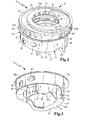
- schematisch eine isometrische Explosionsdarstellung der Bauteile des Abscheiders aus der
Figur 1 ; - Figur 3
- schematisch eine isometrische Darstellung eines Gehäuseunterteils des Abscheiders aus den
Figuren 1 und2 von schräg unten betrachtet; - Figur 4
- schematisch eine isometrische Darstellung des Gehäuseunterteils des Abscheiders aus den
Figuren 1 bis 3 von schräg oben betrachtet; - Figur 5
- schematisch eine isometrische Darstellung des Gehäuseunterteils des Abscheiders aus den
Figuren 1 bis 4 im Teilschnitt von schräg oben betrachtet. - In
Figur 1 ist eine insgesamt mit dem Bezugszeichen 10 versehene Luftaufbereitungsvorrichtung einer ansonsten nicht gezeigten Luftdruckbremsanlage dargestellt. Die Luftaufbereitungsvorrichtung 10 umfasst in derFigur 1 oben einen Abscheider 12 für flüssige Fluide, beispielsweise Öl und Wasser, aus der aufzubereitenden Druckluft. Der Abscheider 12 ist von oben in einem Lufttrocknergehäuse 13 eingesteckt. - Der Abscheider 12 ist aus Kunststoff. Er weist ein in den
Figuren 2 bis 5 gezeigtes zylindrisches Gehäuseunterteil 14 und einen in denFiguren 1 und2 gezeigten Gehäusedeckel 16 auf. - Das Gehäuseunterteil 14 verfügt über eine Außenwandung 18 und eine zu dieser koaxiale ebenfalls zylinderförmige Innenwandung 20.
- Die Außenwandung 18, die Innenwandung 20, der Gehäusedeckel 16 und ein Gehäuseboden 21 begrenzen einen Abscheidekanal 23, den die zu reinigende Luft vom Gehäusedeckel 16 aus betrachtet im Uhrzeigersinn durchströmen kann. Der Abscheidekanal 23 weist vier Abschnitte auf, nämlich in Strömungsrichtung betrachtet einen Eintrittsabschnitt 23a, einen Prallabschnitt 23b, einen Fluidaustrittsabschnitt 23c und einen Luftrampenabschnitt 23d. Der Eintrittsabschnitt 23a, der Prallabschnitt 23b und der Fluidaustrittsabschnitt 23c erstrecken sich entlang des Strömungsweges jeweils etwa über ein Drittel des Umfangs des Gehäuseunterteils 14. Der Luftrampenabschnitt 23d verläuft parallel zum Eintrittsabschnitt 23a und grenzt durch eine Zwischenwand 25 von letzterem getrennt an dessen radial innere Seite an. Die Zwischenwand 25 erstreckt sich vom Gehäuseboden 21 bis zum Gehäusedeckel 16. Sie ist am Gehäuseboden 21 angeformt und gegenüber dem Gehäusedeckel 16 abgedichtet.
- Im Eintrittsabschnitt 23a und im Prallabschnitt 23b nimmt der axiale Abstand des Gehäusebodens 21 vom Gehäusedeckel 16 in Hauptströmungsrichtung zu, so dass der Gehäuseboden 21 in eingebautem Zustand, in dem die Gehäuseachse vertikal verläuft, ein Gefälle aufweist, wodurch das abgeschiedene Fluid besser ablaufen kann. Der dem Gehäuseboden 21 zugewandte Rand der Außenwandung 18 schließt mit dem Gehäuseboden 21 ab. Ebenso schließt der untere Rand der Innenwandung 20 dort, wo er auf den Gehäuseboden 21 stößt, mit diesem ab. So werden unnötigen Hohlräume vermieden, wodurch der Herstellungsprozess des Gehäuseunterteils 14 vereinfacht wird. Die oberen, dem Gehäusedeckel 16 zugewandten Ränder der Außenwandung 18 und der Innenwandung 20 verlaufen eben.
- Am Anfang des Eintrittsabschnitts 23a ist in der Außenwandung 18 eine Eintrittsöffnung 27 für zu reinigende Luft angeordnet. Dort ist der Gehäuseboden 21 dem Gehäusedeckel 16 am nächsten, so dass in eingebautem Zustand dort die höchste Lage des Gehäusebodens 21 ist. Stromabwärts der Eintrittsöffnung 27 kurz vor dem Ende des Eintrittsabschnitts 23a befindet sich in der Außenwandung 18 eine in der
Figur 5 gezeigte sekundäre Eintrittsöffnung 29, über die in hier nicht weiter interessierender Weise im Kreislauf geführte Luft, beispielsweise ein Leckageluftstrom, zugeführt werden kann. Am Ende des Eintrittsabschnitts 23a endet auch die Zwischenwand 25. - Im Prallabschnitt 23b weist die Außenwandung 18 einen radial nach innen gebogenen Abschnittsteil 31 auf. An der radial innersten Stelle des Abschnittsteils 31, die einen im Vergleich zum Eintrittsabschnitt 23a verringerten Radius hat, ist eine erste Prallwand 33 angeformt. Die erste Prallwand 33 erstreckt sich in radialer Richtung und in axialer Richtung, weist also eine zum Hauptströmungsweg senkrechte Flächenkomponente auf.
- Stromabwärts der ersten Prallwand 33 ist zu dieser versetzt eine zweite Prallwand 35 an der radial äußeren Seite der Innenwandung 20 angeformt. Die zweite Prallwand 35 erstreckt sich ebenso wie die erste Prallwand 33 axial und etwa radial zu Gehäuseunterteil 14. Die beiden Prallwände 33 und 35 realisieren gemeinsam mit dem Abschnittsteil 31 einen labyrinthartigen Strömungsweg, in dem die flüssigen Fluide aufgrund ihrer Massenträgheit gegen die Außenwandung 18 beziehungsweise gegen die Prallwände 33 und 35 prallen und dort als Film zunächst haften bleiben, und dann der Schwerkraft folgend zum Gehäuseboden 21 sinken.
- Stromabwärts des Abschnittsteils 31 weist die Außenwandung 18 einen geraden Abschnittsteil 37 auf, der eine die Gehäuseachse nicht schneidende Sekante der Innenkontur der Außenwandung 18 darstellt. Der gerade Abschnittsteil 37 realisiert eine Querschnittsverkleinerung des Abscheidekanals 23 und eine schräge Prallfläche für die Fluide.
- Auf dem Strömungsweg kurz vor dem Ende des Prallabscheideabschnitts weist die Außenwandung 18 eine weitere radial nach innen geformte Erhebung 39 auf, welche zu einer weiteren Querschnittsverkleinerung des Abscheidekanals 23 führt.
- Im stromabwärts folgenden Fluidaustrittsabschnitt 23c ist der Gehäuseboden 21 unterbrochen. Die Unterbrechung bildet eine Fluid-Austrittsöffnung 41 für das abgeschiedene Fluid. Stromabwärts der Fluid-Austrittsöffnung 41 ist unten am Gehäuseboden 21 eine Prallplatte 43 einstückig angeformt, welche sich senkrecht zur Hauptströmungsrichtung axial und etwa radial zur Gehäuseachse erstreckt.
- An den Fluidaustrittsabschnitt 23c schließt sich der Luftrampenabschnitt 23d an. Am Anfang des Luftrampenabschnitts 23d befindet sich der Gehäuseboden 21 etwa auf gleicher axialer Höhe wie am Anfang des Eintrittsabschnitts 23a. Im Verlauf des Luftrampenabschnitts 23d nimmt der axiale Abstand des Gehäusebodens 21 zu dem Gehäusedeckel 16 kontinuierlich ab; der ansteigende Gehäuseboden 21 bildet so eine Luftleitrampe 45. In einem Bereich zwischen der Fluid-Austrittsöffnung 41 und einem sich radial zur Gehäuseachse erstreckenden Abschnitt der Zwischenwand 25, der auch die Begrenzung am Anfang des Eintrittsabschnitts 23a bildet und als weitere radial außen gelegene Prallfläche wirkt, erstreckt sich der Luftrampenabschnitt 23d in radialer Richtung über die gesamten Ausdehnung zwischen der Außenwandung 18 und der Innenwandung 20. Dort weist die Außenwandung 18 eine weitere Öffnung 47 auf, an die beispielsweise ein nicht gezeigter Drucksensor angeschlossen werden kann.
- Der Gehäusedeckel 14 weist an seiner dem Abscheidekanal 23 abgewandten Oberseite einen Aufbau 49 auf, der sich in Umfangsrichtung oberhalb des Luftrampenabschnitts 23d und des Fluidaustrittsabschnitts 23c erstreckt. Der Aufbau 49 ist zum Abscheidekanal 23 hin offen. Im Bereich des Luftrampenabschnitts 23d ist der Aufbau 49 in radialer Richtung gegenüber dem Bereich oberhalb des Fluidaustrittsabschnitts 23c verjüngt, so dass er sich dort nur über den Luftrampenabschnitt 23d erstreckt, nicht jedoch über den Eintrittsabschnitt 23a.
- Der Aufbau 49 weist eine radial innere und eine radial äußere Seitenwand auf, in denen sich jeweils eine Mehrzahl von Reinluft-Austrittsöffnungen 51 befindet. Die Strömungsquerschnitte der von der Luftleitrampe 45 am weiter entfernten Reinluft-Austrittsöffnungen 51 sind größer als die Strömungsquerschnitte der näher gelegenen Reinluft-Austrittsöffnungen 51.
- Der obere Rand der Außenwandung 18 weist einen radial nach außen gebogenen Kragen 53 auf, der eine Aufnahme für eine in der
Figur 2 gezeigte umlaufende O-Ring Dichtung 55 bildet. Der Gehäusedeckel 16 weist eine mit dem Kragen 53 korrespondierende umfängliche Stufe 57 auf. - Die Innenwandung 20 verfügt im Bereich ihres dem Gehäusedeckel 16 zugewandten oberen Randes an der radial inneren Seite über eine umfängliche Stufe 59. Die Stufe 59 dient zur Aufnahme eines Ringstegs 61, der sich an der dem Gehäuseunterteil 14 zugewandten Unterseite des Gehäusedeckels 16 befindet. Zwischen dem Ringsteg 61 und der Stufe 59 ist eine zweite O-Ring Dichtung 63 angeordnet, die das Gehäuse des Abscheiders 12 dort abdichtet.
- Bei der Montage des Abscheiders 12 werden zunächst die O-Ring Dichtungen 55 und 63 am Gehäuseunterteil 14 platziert. Anschließend wird der Gehäusedeckel 16 in axialer Richtung auf das Gehäuseunterteil 14 montiert und mittels Ultraschallschweißen oder Verkleben mit diesem verbunden. Der so vormontierte Abscheider 12 wird dann von oben in das Lufttrocknergehäuse 13 eingesteckt. Die Eintrittsöffnung 27 und die sekundäre Eintrittsöffnung 29 sind über in den
Figuren 1 bis 5 nicht gezeigte angespritzte Dichtlippen gegen entsprechende Luftkanäle im Lufttrocknergehäuse 13 abgedichtet. - Beim Betrieb der Luftaufbereitungsvorrichtung 10 wird zu reinigende Druckluft, welche flüssige Fluide, beispielsweise Öl- oder Wassertröpfchen, und/oder Schmutzpartikel mit sich führt, in hier nicht weiter interessierender Weise aus einem Druckluftkanal im Lufttrocknergehäuse 13 der Eintrittsöffnung 27 zugeführt. Von dort aus strömt die Druckluft durch den Abscheidekanal 23. Die flüssigen Fluide werden in dem insgesamt spiralförmigen Abscheidekanal 23 radial nach außen zur Außenwandung 18 getragen, wo sie einen Film bilden, der der Schwerkraft folgend nach unten zum Gehäuseboden 21 abfließt. Ebenso werden die Schmutzpartikel nach außen getragen und fallen von dort auf den Gehäuseboden, wo sie von den abgeschiedenen flüssigen Fluiden mitgenommen werden. Die abgeschiedenen flüssigen Fluide fließen dem Gefälle des Gehäusebodens 21 folgend bis zur Fluid-Austrittsöffnung 41, durch den sie aus dem Abscheidekanal 23 austreten. Flüssige Fluide und Schmutzpartikel, die nicht bereits im Eintrittsbereich an der Außenwandung 18 abgeschieden werden, prallen beim Durchströmen der labyrinthartigen Bereiche des Prallabscheideabschnitts gegen die Prallwände 33 oder 35, bilden dort einen Film und sinken zum Gehäuseboden 21. An der Erhebung 39 oder an der Prallplatte 43 werden bis dorthin noch mit der Druckluft mitgeführte Fluide abgeschieden.
- Stromabwärts der Fluid-Austrittsöffnung 41 wird die gereinigte Druckluft über die Luftleitrampe 45 nach oben zu dem Aufbau 49 zunächst in axiale Richtung umgeleitet und strömt dort nach einer erneuten Umlenkung in radialer Richtung durch die Reinluft-Austrittsöffnung 51 nach außen. Dabei sorgen die unterschiedlich großen Strömungsquerschnitte dafür, dass die Reinluft durch alle Reinluft-Austrittsöffnungen 51 gleichmäßig ausströmen kann.
- Mit dem Abscheider 12 werden auf diese Weise alle flüssigen Fluide und Schmutzpartikel, die mit der Druckluft der Luftaufbereitungsvorrichtung 10 zugeführt werden, abgeschieden, so dass sie sich nicht als kuchenartige Fluid - und/oder Schmutzmasse in der Luftdruckbremsanlage niederschlagen können, was zu Problemen führen kann. Durch die radiale Anordnung der Reinluft-Austrittsöffnungen 51 wird darüber hinaus die direkte Sicht in den Abscheidekanal 23 versperrt, so dass Emulsions- und partikelartige Schmutz- und Rußrückstände optisch weitestgehend verborgen bleiben.
- Anstelle der O-Ring Dichtungen 55 und 63 können auch an das Gehäuseunterteil 14 oder dem Gehäusedeckel 16 angespritzte Dichtlamellen oder Dichtlippen zur Abdichtung eingesetzt werden.
Claims (11)
- Luftaufbereitungsvorrichtung (10) insbesondere einer Luftdruckbremsanlage mit einem Abscheider (12) für flüssige Fluide, insbesondere Öl oder Wasser, der ein im Wesentlichen zylindrisches Gehäuse (14, 16) aufweist, das an seinen Stirnseiten über einen Gehäusedeckel (16) und einen Gehäuseboden (21) verfügt, und das in seinem Inneren einen Abscheidekanal (23) aufweist, den die zu reinigende Luft durchströmen kann, wobei der Abscheidekanal (23) in Umfangsrichtung des Gehäuses (14, 16) gebogen verläuft und wenigstens eine Eintrittsöffnung (27) für die zu reinigende Luft, wenigstens eine Fluid-Austrittsöffnung (41) für abgeschiedenes Fluid und wenigstens eine Reinluft-Austrittsöffnung (51) für gereinigte Luft aufweist, dadurch gekennzeichnet, dass der Abscheidekanal (23) stromabwärts der Fluid-Austrittsöffnung (41) eine Luftleitrampe (45) zur Leitung der Reinluft zur Reinluft-Austrittsöffnung (51) aufweist.
- Luftaufbereitungsvorrichtung nach Anspruch 1, dadurch gekennzeichnet, dass der Abscheidekanal (23) grob spiralförmig, schraubenförmig oder zirkulär verläuft.
- Luftaufbereitungsvorrichtung nach Anspruch 1 oder 2, dadurch gekennzeichnet, dass die wenigstens eine Eintrittsöffnung (27) in einer radial äußeren Wand (18) des Abscheidekanals (23) angeordnet ist.
- Luftaufbereitungsvorrichtung nach einem der vorigen Ansprüche, dadurch gekennzeichnet, dass die Innenseite der radial äußeren Wand (18) des Abscheidekanals (23) wenigstens einen Abschnitt (31, 39) mit einem verringerten Radius aufweist.
- Luftaufbereitungsvorrichtung nach einem der vorigen Ansprüche, dadurch gekennzeichnet, dass im Abscheidekanal (23) wenigstens eine Prallwand (33, 35, 43) angeordnet ist, die eine zum Strömungsweg senkrechte Flächenkomponente aufweist.
- Luftaufbereitungsvorrichtung nach Anspruch 5, dadurch gekennzeichnet, dass wenigstens zwei Prallwände (33, 35) labyrinthartig zueinander versetzt angeordnet sind.
- Luftaufbereitungsvorrichtung nach einem der vorigen Ansprüche, dadurch gekennzeichnet, dass der Gehäusedeckel (16) an seiner dem Abscheidekanal (23) abgewandten Außenseite einen Aufbau (49) aufweist, der sich wenigstens im Bereich der Luftleitrampe (45) entlang des Abscheidekanals (23) erstreckt und zum Abscheidekanal (23) hin offen ist, wobei in einer radial inneren und/oder einer radial äußeren Seitenwand des Aufbaus (49) wenigstens eine Reinluft-Austrittsöffnung (51) angeordnet ist.
- Luftaufbereitungsvorrichtung nach Anspruch 7, dadurch gekennzeichnet, dass eine Mehrzahl von Reinluft-Austrittsöffnungen (51) in der radial inneren und/oder der radial äußeren Seitenwand des Aufbaus (49) angeordnet ist.
- Luftaufbereitungsvorrichtung nach Anspruch 8, dadurch gekennzeichnet, dass die Strömungsquerschnitte der von der Luftleitrampe (45) weiter entfernten Reinluft-Austrittsöffnungen (51) größer sind als die Strömungsquerschnitte der näher gelegenen Reinluft-Austrittsöffnungen (51).
- Luftaufbereitungsvorrichtung nach einem der vorigen Ansprüche, dadurch gekennzeichnet, dass wenigstens eine Fluid-Austrittsöffnung (41) im Gehäuseboden (21) angeordnet ist.
- Abscheider (12) für flüssiges Fluid einer Luftaufbereitungsvorrichtung (10) nach einem der vorigen Ansprüche.
Applications Claiming Priority (1)
| Application Number | Priority Date | Filing Date | Title |
|---|---|---|---|
| DE202008007635U DE202008007635U1 (de) | 2008-06-06 | 2008-06-06 | Luftaufbereitungsvorrichtung, insbesondere einer Luftdruckbremsanlage mit einem Abscheider für flüssige Fluide |
Publications (2)
| Publication Number | Publication Date |
|---|---|
| EP2130577A1 true EP2130577A1 (de) | 2009-12-09 |
| EP2130577B1 EP2130577B1 (de) | 2015-12-02 |
Family
ID=41100756
Family Applications (1)
| Application Number | Title | Priority Date | Filing Date |
|---|---|---|---|
| EP09161224.2A Revoked EP2130577B1 (de) | 2008-06-06 | 2009-05-27 | Luftaufbereitungsvorrichtung, insbesondere einer Luftdruckbremsanlage mit einem Abscheider für flüssige Fluide |
Country Status (2)
| Country | Link |
|---|---|
| EP (1) | EP2130577B1 (de) |
| DE (1) | DE202008007635U1 (de) |
Families Citing this family (2)
| Publication number | Priority date | Publication date | Assignee | Title |
|---|---|---|---|---|
| DE102018212211A1 (de) * | 2018-07-23 | 2020-01-23 | Robert Bosch Gmbh | Abgasmantel für einen Brennwertkessel |
| DE102019103807B4 (de) * | 2019-02-14 | 2022-09-29 | Ibs Filtran Kunststoff-/ Metallerzeugnisse Gmbh | Filtervorrichtung, Verwendung der Filtervorrichtung sowie Verfahren zum Abscheiden von Partikeln |
Citations (5)
| Publication number | Priority date | Publication date | Assignee | Title |
|---|---|---|---|---|
| WO1995007831A1 (en) * | 1993-09-14 | 1995-03-23 | Horton Industries, Inc. | Device for cleaning and drying compressed gas |
| DE19627889A1 (de) * | 1996-07-11 | 1998-01-15 | Knecht Filterwerke Gmbh | Lufttrockner, insbesondere für Druckluftbremsanlagen |
| EP1048540A1 (de) * | 1999-04-28 | 2000-11-02 | Baldwin Filters, Inc. | Lufttrocknungskanister |
| EP1529562A1 (de) * | 2003-11-06 | 2005-05-11 | Haldex Brake Products GmbH | Verfahren zum Reinigen von Druckluft an Druckluftbeschaffungsanlagen von Kraftfahrzeugen sowie Kartusche hierfür |
| DE102005017511A1 (de) | 2004-04-15 | 2005-11-17 | Knorr-Bremse Systeme für Nutzfahrzeuge GmbH | Luftaufbereitungsanlage mit Ölabscheider und Druckluftversorgungsanlage |
Family Cites Families (9)
| Publication number | Priority date | Publication date | Assignee | Title |
|---|---|---|---|---|
| US2229860A (en) * | 1938-11-14 | 1941-01-28 | Mccurdy Howard | Helical centrifugal separator |
| DE1258335B (de) * | 1966-02-21 | 1968-01-04 | Molekularzerstaeubung Meissen | Vorrichtung zum Abscheiden von Feststoffteilchen aus einem gasfoermigen Foerdermittel |
| DE7017459U (de) | 1970-05-09 | 1973-07-19 | Calor Emag Elektrizitaets Ag | Fluessigkeitsabscheider fuer den schaltgasabzug von fluessigkeitsschaltern. |
| DE2250841B2 (de) * | 1972-10-17 | 1980-01-31 | Koerting Ag, 3000 Hannover | Fliehkraftabscheider für feste und flüssige Stoffe aus Gasen |
| DE2606673C2 (de) * | 1976-02-19 | 1983-12-08 | Klöckner-Humboldt-Deutz AG, 5000 Köln | Vorrichtung zum Ausscheiden von Gasen aus Flüssigkeiten |
| DE3263965D1 (en) * | 1982-01-28 | 1985-07-11 | Chang Ying Chung | Separator for compressed air |
| DE10340122A1 (de) * | 2003-08-30 | 2004-02-26 | Mann + Hummel Gmbh | Vorrichtung zur Trennung von Partikeln aus einem Mediumstrom |
| DE102005013473A1 (de) * | 2005-03-21 | 2006-09-28 | Knorr-Bremse Systeme für Nutzfahrzeuge GmbH | Ölabscheider, Luftaufbereitungsanlage und Druckluftversorgungseinrichtung |
| DE102005036468A1 (de) | 2005-08-03 | 2007-02-08 | Hager, Michael, Dr.-Ing. | Raumluftfiltervorrichtung |
-
2008
- 2008-06-06 DE DE202008007635U patent/DE202008007635U1/de not_active Expired - Lifetime
-
2009
- 2009-05-27 EP EP09161224.2A patent/EP2130577B1/de not_active Revoked
Patent Citations (5)
| Publication number | Priority date | Publication date | Assignee | Title |
|---|---|---|---|---|
| WO1995007831A1 (en) * | 1993-09-14 | 1995-03-23 | Horton Industries, Inc. | Device for cleaning and drying compressed gas |
| DE19627889A1 (de) * | 1996-07-11 | 1998-01-15 | Knecht Filterwerke Gmbh | Lufttrockner, insbesondere für Druckluftbremsanlagen |
| EP1048540A1 (de) * | 1999-04-28 | 2000-11-02 | Baldwin Filters, Inc. | Lufttrocknungskanister |
| EP1529562A1 (de) * | 2003-11-06 | 2005-05-11 | Haldex Brake Products GmbH | Verfahren zum Reinigen von Druckluft an Druckluftbeschaffungsanlagen von Kraftfahrzeugen sowie Kartusche hierfür |
| DE102005017511A1 (de) | 2004-04-15 | 2005-11-17 | Knorr-Bremse Systeme für Nutzfahrzeuge GmbH | Luftaufbereitungsanlage mit Ölabscheider und Druckluftversorgungsanlage |
Also Published As
| Publication number | Publication date |
|---|---|
| DE202008007635U1 (de) | 2009-10-22 |
| EP2130577B1 (de) | 2015-12-02 |
Similar Documents
| Publication | Publication Date | Title |
|---|---|---|
| EP2052136B1 (de) | Vorrichtung zur abscheidung von flüssigkeiten aus gasen | |
| DE102015006497B4 (de) | Zyklonabscheider sowie Filtervorrichtung mit Zyklonabscheider | |
| DE2328220C2 (de) | Vorrichtung zum Erzeugen einer Wirbelströmung | |
| DE202015008649U1 (de) | Staubsammler für Staubsauger | |
| DE1619866B2 (de) | Trennvorrichtung fuer in gasen enthaltene/ fluessigkeiten | |
| EP2201879A2 (de) | Staubsauger mit Fliehkraftabscheidern | |
| DE10330296A1 (de) | Abscheidevorrichtung | |
| DE102005022851A1 (de) | Multizyklon-Staubsammelvorrichtung | |
| DE102011110499A1 (de) | Ölnebelabscheider zur Abscheidung von aerosolem Öl aus einem ölbeladenen Gas | |
| EP2049222A1 (de) | Filtervorrichtung | |
| WO2009138384A1 (de) | Abscheider für eine kurbelgehäuseentlüftung einer brennkraftmaschine | |
| DE202007007120U1 (de) | Kraftstoffzuführeinrichtung, insbesondere für eine Brennkraftmaschine | |
| DE102004035688A1 (de) | Vorrichtung zur Trennung von Partikeln aus einem Medienstrom | |
| DE112019000506B4 (de) | Filtereinrichtung, insbesondere zur gasfiltration | |
| EP1364696B1 (de) | Vorrichtung zur Reinigung eines Gasstromes | |
| EP2130577B1 (de) | Luftaufbereitungsvorrichtung, insbesondere einer Luftdruckbremsanlage mit einem Abscheider für flüssige Fluide | |
| DE102012007308B4 (de) | Abscheidevorrichtung | |
| WO2019145133A1 (de) | Filtergehäuse für eine filtereinrichtung | |
| DE102004005500A1 (de) | Staubsauger | |
| DE10393196T5 (de) | Zentrifugalabscheider | |
| WO2005022046A1 (de) | Vorrichtung zum absaugen insbesondere von mit schadstoffen belasteter luft | |
| DE202017007339U1 (de) | Abscheidesystem | |
| DE102010063843A1 (de) | Dunstabzugshaube und Verfahren zum Abscheiden von Aerosolen | |
| DE202009016309U1 (de) | Einrichtung zur Trennung eines Gas-Flüssigkeit-Gemischs | |
| CH665135A5 (de) | Fliehkraftabscheider. |
Legal Events
| Date | Code | Title | Description |
|---|---|---|---|
| PUAI | Public reference made under article 153(3) epc to a published international application that has entered the european phase |
Free format text: ORIGINAL CODE: 0009012 |
|
| AK | Designated contracting states |
Kind code of ref document: A1 Designated state(s): AT BE BG CH CY CZ DE DK EE ES FI FR GB GR HR HU IE IS IT LI LT LU LV MC MK MT NL NO PL PT RO SE SI SK TR |
|
| 17P | Request for examination filed |
Effective date: 20100112 |
|
| 17Q | First examination report despatched |
Effective date: 20100205 |
|
| GRAP | Despatch of communication of intention to grant a patent |
Free format text: ORIGINAL CODE: EPIDOSNIGR1 |
|
| INTG | Intention to grant announced |
Effective date: 20150724 |
|
| GRAS | Grant fee paid |
Free format text: ORIGINAL CODE: EPIDOSNIGR3 |
|
| GRAA | (expected) grant |
Free format text: ORIGINAL CODE: 0009210 |
|
| RIN1 | Information on inventor provided before grant (corrected) |
Inventor name: ZWISLER, JOHANNES Inventor name: EBERLE, JUERGEN Inventor name: AMESOEDER, DIETER Inventor name: NIEMEYER, STEPHAN Inventor name: SCHLEIDEN, THOMAS Inventor name: KOCH, EUGEN |
|
| AK | Designated contracting states |
Kind code of ref document: B1 Designated state(s): AT BE BG CH CY CZ DE DK EE ES FI FR GB GR HR HU IE IS IT LI LT LU LV MC MK MT NL NO PL PT RO SE SI SK TR |
|
| REG | Reference to a national code |
Ref country code: GB Ref legal event code: FG4D Free format text: NOT ENGLISH |
|
| REG | Reference to a national code |
Ref country code: AT Ref legal event code: REF Ref document number: 763368 Country of ref document: AT Kind code of ref document: T Effective date: 20151215 Ref country code: CH Ref legal event code: EP |
|
| REG | Reference to a national code |
Ref country code: IE Ref legal event code: FG4D Free format text: LANGUAGE OF EP DOCUMENT: GERMAN |
|
| REG | Reference to a national code |
Ref country code: DE Ref legal event code: R096 Ref document number: 502009011885 Country of ref document: DE |
|
| REG | Reference to a national code |
Ref country code: NL Ref legal event code: MP Effective date: 20160302 |
|
| REG | Reference to a national code |
Ref country code: LT Ref legal event code: MG4D |
|
| PG25 | Lapsed in a contracting state [announced via postgrant information from national office to epo] |
Ref country code: NO Free format text: LAPSE BECAUSE OF FAILURE TO SUBMIT A TRANSLATION OF THE DESCRIPTION OR TO PAY THE FEE WITHIN THE PRESCRIBED TIME-LIMIT Effective date: 20160302 Ref country code: LT Free format text: LAPSE BECAUSE OF FAILURE TO SUBMIT A TRANSLATION OF THE DESCRIPTION OR TO PAY THE FEE WITHIN THE PRESCRIBED TIME-LIMIT Effective date: 20151202 Ref country code: HR Free format text: LAPSE BECAUSE OF FAILURE TO SUBMIT A TRANSLATION OF THE DESCRIPTION OR TO PAY THE FEE WITHIN THE PRESCRIBED TIME-LIMIT Effective date: 20151202 Ref country code: ES Free format text: LAPSE BECAUSE OF FAILURE TO SUBMIT A TRANSLATION OF THE DESCRIPTION OR TO PAY THE FEE WITHIN THE PRESCRIBED TIME-LIMIT Effective date: 20151202 |
|
| PG25 | Lapsed in a contracting state [announced via postgrant information from national office to epo] |
Ref country code: NL Free format text: LAPSE BECAUSE OF FAILURE TO SUBMIT A TRANSLATION OF THE DESCRIPTION OR TO PAY THE FEE WITHIN THE PRESCRIBED TIME-LIMIT Effective date: 20151202 Ref country code: FI Free format text: LAPSE BECAUSE OF FAILURE TO SUBMIT A TRANSLATION OF THE DESCRIPTION OR TO PAY THE FEE WITHIN THE PRESCRIBED TIME-LIMIT Effective date: 20151202 Ref country code: GR Free format text: LAPSE BECAUSE OF FAILURE TO SUBMIT A TRANSLATION OF THE DESCRIPTION OR TO PAY THE FEE WITHIN THE PRESCRIBED TIME-LIMIT Effective date: 20160303 Ref country code: SE Free format text: LAPSE BECAUSE OF FAILURE TO SUBMIT A TRANSLATION OF THE DESCRIPTION OR TO PAY THE FEE WITHIN THE PRESCRIBED TIME-LIMIT Effective date: 20151202 Ref country code: PL Free format text: LAPSE BECAUSE OF FAILURE TO SUBMIT A TRANSLATION OF THE DESCRIPTION OR TO PAY THE FEE WITHIN THE PRESCRIBED TIME-LIMIT Effective date: 20151202 Ref country code: LV Free format text: LAPSE BECAUSE OF FAILURE TO SUBMIT A TRANSLATION OF THE DESCRIPTION OR TO PAY THE FEE WITHIN THE PRESCRIBED TIME-LIMIT Effective date: 20151202 |
|
| PG25 | Lapsed in a contracting state [announced via postgrant information from national office to epo] |
Ref country code: IS Free format text: LAPSE BECAUSE OF FAILURE TO SUBMIT A TRANSLATION OF THE DESCRIPTION OR TO PAY THE FEE WITHIN THE PRESCRIBED TIME-LIMIT Effective date: 20151202 |
|
| PG25 | Lapsed in a contracting state [announced via postgrant information from national office to epo] |
Ref country code: IT Free format text: LAPSE BECAUSE OF FAILURE TO SUBMIT A TRANSLATION OF THE DESCRIPTION OR TO PAY THE FEE WITHIN THE PRESCRIBED TIME-LIMIT Effective date: 20151202 Ref country code: CZ Free format text: LAPSE BECAUSE OF FAILURE TO SUBMIT A TRANSLATION OF THE DESCRIPTION OR TO PAY THE FEE WITHIN THE PRESCRIBED TIME-LIMIT Effective date: 20151202 |
|
| PG25 | Lapsed in a contracting state [announced via postgrant information from national office to epo] |
Ref country code: SK Free format text: LAPSE BECAUSE OF FAILURE TO SUBMIT A TRANSLATION OF THE DESCRIPTION OR TO PAY THE FEE WITHIN THE PRESCRIBED TIME-LIMIT Effective date: 20151202 Ref country code: PT Free format text: LAPSE BECAUSE OF FAILURE TO SUBMIT A TRANSLATION OF THE DESCRIPTION OR TO PAY THE FEE WITHIN THE PRESCRIBED TIME-LIMIT Effective date: 20160404 Ref country code: RO Free format text: LAPSE BECAUSE OF FAILURE TO SUBMIT A TRANSLATION OF THE DESCRIPTION OR TO PAY THE FEE WITHIN THE PRESCRIBED TIME-LIMIT Effective date: 20151202 Ref country code: BE Free format text: LAPSE BECAUSE OF NON-PAYMENT OF DUE FEES Effective date: 20160531 Ref country code: EE Free format text: LAPSE BECAUSE OF FAILURE TO SUBMIT A TRANSLATION OF THE DESCRIPTION OR TO PAY THE FEE WITHIN THE PRESCRIBED TIME-LIMIT Effective date: 20151202 Ref country code: IS Free format text: LAPSE BECAUSE OF FAILURE TO SUBMIT A TRANSLATION OF THE DESCRIPTION OR TO PAY THE FEE WITHIN THE PRESCRIBED TIME-LIMIT Effective date: 20160402 |
|
| REG | Reference to a national code |
Ref country code: DE Ref legal event code: R026 Ref document number: 502009011885 Country of ref document: DE |
|
| PLBI | Opposition filed |
Free format text: ORIGINAL CODE: 0009260 |
|
| 26 | Opposition filed |
Opponent name: KNORR-BREMSE SYSTEME FUER NUTZFAHRZEUGE GMBH Effective date: 20160831 |
|
| PLAX | Notice of opposition and request to file observation + time limit sent |
Free format text: ORIGINAL CODE: EPIDOSNOBS2 |
|
| PG25 | Lapsed in a contracting state [announced via postgrant information from national office to epo] |
Ref country code: DK Free format text: LAPSE BECAUSE OF FAILURE TO SUBMIT A TRANSLATION OF THE DESCRIPTION OR TO PAY THE FEE WITHIN THE PRESCRIBED TIME-LIMIT Effective date: 20151202 |
|
| PG25 | Lapsed in a contracting state [announced via postgrant information from national office to epo] |
Ref country code: SI Free format text: LAPSE BECAUSE OF FAILURE TO SUBMIT A TRANSLATION OF THE DESCRIPTION OR TO PAY THE FEE WITHIN THE PRESCRIBED TIME-LIMIT Effective date: 20151202 |
|
| PG25 | Lapsed in a contracting state [announced via postgrant information from national office to epo] |
Ref country code: LU Free format text: LAPSE BECAUSE OF FAILURE TO SUBMIT A TRANSLATION OF THE DESCRIPTION OR TO PAY THE FEE WITHIN THE PRESCRIBED TIME-LIMIT Effective date: 20160527 |
|
| REG | Reference to a national code |
Ref country code: CH Ref legal event code: PL |
|
| GBPC | Gb: european patent ceased through non-payment of renewal fee |
Effective date: 20160527 |
|
| PG25 | Lapsed in a contracting state [announced via postgrant information from national office to epo] |
Ref country code: CH Free format text: LAPSE BECAUSE OF NON-PAYMENT OF DUE FEES Effective date: 20160531 Ref country code: LI Free format text: LAPSE BECAUSE OF NON-PAYMENT OF DUE FEES Effective date: 20160531 |
|
| PLBB | Reply of patent proprietor to notice(s) of opposition received |
Free format text: ORIGINAL CODE: EPIDOSNOBS3 |
|
| REG | Reference to a national code |
Ref country code: IE Ref legal event code: MM4A |
|
| REG | Reference to a national code |
Ref country code: FR Ref legal event code: ST Effective date: 20170131 |
|
| PG25 | Lapsed in a contracting state [announced via postgrant information from national office to epo] |
Ref country code: FR Free format text: LAPSE BECAUSE OF NON-PAYMENT OF DUE FEES Effective date: 20160531 |
|
| PG25 | Lapsed in a contracting state [announced via postgrant information from national office to epo] |
Ref country code: GB Free format text: LAPSE BECAUSE OF NON-PAYMENT OF DUE FEES Effective date: 20160527 Ref country code: IE Free format text: LAPSE BECAUSE OF NON-PAYMENT OF DUE FEES Effective date: 20160527 |
|
| REG | Reference to a national code |
Ref country code: AT Ref legal event code: MM01 Ref document number: 763368 Country of ref document: AT Kind code of ref document: T Effective date: 20160527 |
|
| PG25 | Lapsed in a contracting state [announced via postgrant information from national office to epo] |
Ref country code: AT Free format text: LAPSE BECAUSE OF NON-PAYMENT OF DUE FEES Effective date: 20160527 |
|
| APAH | Appeal reference modified |
Free format text: ORIGINAL CODE: EPIDOSCREFNO |
|
| APBM | Appeal reference recorded |
Free format text: ORIGINAL CODE: EPIDOSNREFNO |
|
| APBP | Date of receipt of notice of appeal recorded |
Free format text: ORIGINAL CODE: EPIDOSNNOA2O |
|
| PG25 | Lapsed in a contracting state [announced via postgrant information from national office to epo] |
Ref country code: CY Free format text: LAPSE BECAUSE OF FAILURE TO SUBMIT A TRANSLATION OF THE DESCRIPTION OR TO PAY THE FEE WITHIN THE PRESCRIBED TIME-LIMIT Effective date: 20151202 Ref country code: HU Free format text: LAPSE BECAUSE OF FAILURE TO SUBMIT A TRANSLATION OF THE DESCRIPTION OR TO PAY THE FEE WITHIN THE PRESCRIBED TIME-LIMIT; INVALID AB INITIO Effective date: 20090527 |
|
| PG25 | Lapsed in a contracting state [announced via postgrant information from national office to epo] |
Ref country code: TR Free format text: LAPSE BECAUSE OF FAILURE TO SUBMIT A TRANSLATION OF THE DESCRIPTION OR TO PAY THE FEE WITHIN THE PRESCRIBED TIME-LIMIT Effective date: 20151202 Ref country code: MK Free format text: LAPSE BECAUSE OF FAILURE TO SUBMIT A TRANSLATION OF THE DESCRIPTION OR TO PAY THE FEE WITHIN THE PRESCRIBED TIME-LIMIT Effective date: 20151202 Ref country code: MC Free format text: LAPSE BECAUSE OF FAILURE TO SUBMIT A TRANSLATION OF THE DESCRIPTION OR TO PAY THE FEE WITHIN THE PRESCRIBED TIME-LIMIT Effective date: 20151202 Ref country code: MT Free format text: LAPSE BECAUSE OF FAILURE TO SUBMIT A TRANSLATION OF THE DESCRIPTION OR TO PAY THE FEE WITHIN THE PRESCRIBED TIME-LIMIT Effective date: 20151202 |
|
| APBQ | Date of receipt of statement of grounds of appeal recorded |
Free format text: ORIGINAL CODE: EPIDOSNNOA3O |
|
| REG | Reference to a national code |
Ref country code: DE Ref legal event code: R081 Ref document number: 502009011885 Country of ref document: DE Owner name: MANN+HUMMEL GMBH, DE Free format text: FORMER OWNER: MANN + HUMMEL GMBH, 71638 LUDWIGSBURG, DE |
|
| PG25 | Lapsed in a contracting state [announced via postgrant information from national office to epo] |
Ref country code: BG Free format text: LAPSE BECAUSE OF FAILURE TO SUBMIT A TRANSLATION OF THE DESCRIPTION OR TO PAY THE FEE WITHIN THE PRESCRIBED TIME-LIMIT Effective date: 20151202 |
|
| RAP4 | Party data changed (patent owner data changed or rights of a patent transferred) |
Owner name: MANN+HUMMEL GMBH |
|
| PGFP | Annual fee paid to national office [announced via postgrant information from national office to epo] |
Ref country code: DE Payment date: 20220519 Year of fee payment: 14 |
|
| REG | Reference to a national code |
Ref country code: DE Ref legal event code: R103 Ref document number: 502009011885 Country of ref document: DE Ref country code: DE Ref legal event code: R064 Ref document number: 502009011885 Country of ref document: DE |
|
| APBU | Appeal procedure closed |
Free format text: ORIGINAL CODE: EPIDOSNNOA9O |
|
| RDAF | Communication despatched that patent is revoked |
Free format text: ORIGINAL CODE: EPIDOSNREV1 |
|
| STAA | Information on the status of an ep patent application or granted ep patent |
Free format text: STATUS: PATENT REVOKED |
|
| RDAG | Patent revoked |
Free format text: ORIGINAL CODE: 0009271 |
|
| 27W | Patent revoked |
Effective date: 20220929 |
|
| REG | Reference to a national code |
Ref country code: AT Ref legal event code: MA03 Ref document number: 763368 Country of ref document: AT Kind code of ref document: T Effective date: 20220929 |