EP2130504A1 - Articulated bending mechanism and articulated medical device with articulated bending mechanism - Google Patents
Articulated bending mechanism and articulated medical device with articulated bending mechanism Download PDFInfo
- Publication number
- EP2130504A1 EP2130504A1 EP07851065A EP07851065A EP2130504A1 EP 2130504 A1 EP2130504 A1 EP 2130504A1 EP 07851065 A EP07851065 A EP 07851065A EP 07851065 A EP07851065 A EP 07851065A EP 2130504 A1 EP2130504 A1 EP 2130504A1
- Authority
- EP
- European Patent Office
- Prior art keywords
- bending
- manipulation
- bending piece
- guide
- wires
- Prior art date
- Legal status (The legal status is an assumption and is not a legal conclusion. Google has not performed a legal analysis and makes no representation as to the accuracy of the status listed.)
- Pending
Links
Images










Classifications
-
- A—HUMAN NECESSITIES
- A61—MEDICAL OR VETERINARY SCIENCE; HYGIENE
- A61B—DIAGNOSIS; SURGERY; IDENTIFICATION
- A61B1/00—Instruments for performing medical examinations of the interior of cavities or tubes of the body by visual or photographical inspection, e.g. endoscopes; Illuminating arrangements therefor
- A61B1/005—Flexible endoscopes
- A61B1/0051—Flexible endoscopes with controlled bending of insertion part
- A61B1/0055—Constructional details of insertion parts, e.g. vertebral elements
-
- A—HUMAN NECESSITIES
- A61—MEDICAL OR VETERINARY SCIENCE; HYGIENE
- A61B—DIAGNOSIS; SURGERY; IDENTIFICATION
- A61B1/00—Instruments for performing medical examinations of the interior of cavities or tubes of the body by visual or photographical inspection, e.g. endoscopes; Illuminating arrangements therefor
- A61B1/00131—Accessories for endoscopes
- A61B1/00133—Drive units for endoscopic tools inserted through or with the endoscope
-
- A—HUMAN NECESSITIES
- A61—MEDICAL OR VETERINARY SCIENCE; HYGIENE
- A61B—DIAGNOSIS; SURGERY; IDENTIFICATION
- A61B1/00—Instruments for performing medical examinations of the interior of cavities or tubes of the body by visual or photographical inspection, e.g. endoscopes; Illuminating arrangements therefor
- A61B1/005—Flexible endoscopes
- A61B1/0051—Flexible endoscopes with controlled bending of insertion part
- A61B1/0057—Constructional details of force transmission elements, e.g. control wires
-
- A—HUMAN NECESSITIES
- A61—MEDICAL OR VETERINARY SCIENCE; HYGIENE
- A61B—DIAGNOSIS; SURGERY; IDENTIFICATION
- A61B17/00—Surgical instruments, devices or methods
- A61B17/28—Surgical forceps
- A61B17/29—Forceps for use in minimally invasive surgery
-
- A—HUMAN NECESSITIES
- A61—MEDICAL OR VETERINARY SCIENCE; HYGIENE
- A61B—DIAGNOSIS; SURGERY; IDENTIFICATION
- A61B34/00—Computer-aided surgery; Manipulators or robots specially adapted for use in surgery
- A61B34/30—Surgical robots
-
- A—HUMAN NECESSITIES
- A61—MEDICAL OR VETERINARY SCIENCE; HYGIENE
- A61B—DIAGNOSIS; SURGERY; IDENTIFICATION
- A61B34/00—Computer-aided surgery; Manipulators or robots specially adapted for use in surgery
- A61B34/30—Surgical robots
- A61B34/37—Leader-follower robots
-
- A—HUMAN NECESSITIES
- A61—MEDICAL OR VETERINARY SCIENCE; HYGIENE
- A61B—DIAGNOSIS; SURGERY; IDENTIFICATION
- A61B34/00—Computer-aided surgery; Manipulators or robots specially adapted for use in surgery
- A61B34/70—Manipulators specially adapted for use in surgery
- A61B34/71—Manipulators operated by drive cable mechanisms
-
- A—HUMAN NECESSITIES
- A61—MEDICAL OR VETERINARY SCIENCE; HYGIENE
- A61B—DIAGNOSIS; SURGERY; IDENTIFICATION
- A61B18/00—Surgical instruments, devices or methods for transferring non-mechanical forms of energy to or from the body
- A61B18/04—Surgical instruments, devices or methods for transferring non-mechanical forms of energy to or from the body by heating
- A61B18/12—Surgical instruments, devices or methods for transferring non-mechanical forms of energy to or from the body by heating by passing a current through the tissue to be heated, e.g. high-frequency current
- A61B18/14—Probes or electrodes therefor
- A61B18/1492—Probes or electrodes therefor having a flexible, catheter-like structure, e.g. for heart ablation
-
- A—HUMAN NECESSITIES
- A61—MEDICAL OR VETERINARY SCIENCE; HYGIENE
- A61B—DIAGNOSIS; SURGERY; IDENTIFICATION
- A61B17/00—Surgical instruments, devices or methods
- A61B17/00234—Surgical instruments, devices or methods for minimally invasive surgery
- A61B2017/00292—Surgical instruments, devices or methods for minimally invasive surgery mounted on or guided by flexible, e.g. catheter-like, means
- A61B2017/003—Steerable
-
- A—HUMAN NECESSITIES
- A61—MEDICAL OR VETERINARY SCIENCE; HYGIENE
- A61B—DIAGNOSIS; SURGERY; IDENTIFICATION
- A61B17/00—Surgical instruments, devices or methods
- A61B17/00234—Surgical instruments, devices or methods for minimally invasive surgery
- A61B2017/00292—Surgical instruments, devices or methods for minimally invasive surgery mounted on or guided by flexible, e.g. catheter-like, means
- A61B2017/003—Steerable
- A61B2017/00305—Constructional details of the flexible means
- A61B2017/00314—Separate linked members
-
- A—HUMAN NECESSITIES
- A61—MEDICAL OR VETERINARY SCIENCE; HYGIENE
- A61B—DIAGNOSIS; SURGERY; IDENTIFICATION
- A61B17/00—Surgical instruments, devices or methods
- A61B17/00234—Surgical instruments, devices or methods for minimally invasive surgery
- A61B2017/00292—Surgical instruments, devices or methods for minimally invasive surgery mounted on or guided by flexible, e.g. catheter-like, means
- A61B2017/003—Steerable
- A61B2017/00318—Steering mechanisms
- A61B2017/00323—Cables or rods
-
- A—HUMAN NECESSITIES
- A61—MEDICAL OR VETERINARY SCIENCE; HYGIENE
- A61B—DIAGNOSIS; SURGERY; IDENTIFICATION
- A61B17/00—Surgical instruments, devices or methods
- A61B17/00234—Surgical instruments, devices or methods for minimally invasive surgery
- A61B2017/00292—Surgical instruments, devices or methods for minimally invasive surgery mounted on or guided by flexible, e.g. catheter-like, means
- A61B2017/0034—Surgical instruments, devices or methods for minimally invasive surgery mounted on or guided by flexible, e.g. catheter-like, means adapted to be inserted through a working channel of an endoscope
-
- A—HUMAN NECESSITIES
- A61—MEDICAL OR VETERINARY SCIENCE; HYGIENE
- A61B—DIAGNOSIS; SURGERY; IDENTIFICATION
- A61B17/00—Surgical instruments, devices or methods
- A61B17/28—Surgical forceps
- A61B17/29—Forceps for use in minimally invasive surgery
- A61B2017/2901—Details of shaft
-
- A—HUMAN NECESSITIES
- A61—MEDICAL OR VETERINARY SCIENCE; HYGIENE
- A61B—DIAGNOSIS; SURGERY; IDENTIFICATION
- A61B17/00—Surgical instruments, devices or methods
- A61B17/28—Surgical forceps
- A61B17/29—Forceps for use in minimally invasive surgery
- A61B2017/2926—Details of heads or jaws
- A61B2017/2927—Details of heads or jaws the angular position of the head being adjustable with respect to the shaft
-
- A—HUMAN NECESSITIES
- A61—MEDICAL OR VETERINARY SCIENCE; HYGIENE
- A61B—DIAGNOSIS; SURGERY; IDENTIFICATION
- A61B17/00—Surgical instruments, devices or methods
- A61B17/28—Surgical forceps
- A61B17/29—Forceps for use in minimally invasive surgery
- A61B2017/2926—Details of heads or jaws
- A61B2017/2927—Details of heads or jaws the angular position of the head being adjustable with respect to the shaft
- A61B2017/2929—Details of heads or jaws the angular position of the head being adjustable with respect to the shaft with a head rotatable about the longitudinal axis of the shaft
-
- A—HUMAN NECESSITIES
- A61—MEDICAL OR VETERINARY SCIENCE; HYGIENE
- A61B—DIAGNOSIS; SURGERY; IDENTIFICATION
- A61B17/00—Surgical instruments, devices or methods
- A61B17/28—Surgical forceps
- A61B17/29—Forceps for use in minimally invasive surgery
- A61B2017/2947—Pivots
-
- A—HUMAN NECESSITIES
- A61—MEDICAL OR VETERINARY SCIENCE; HYGIENE
- A61B—DIAGNOSIS; SURGERY; IDENTIFICATION
- A61B18/00—Surgical instruments, devices or methods for transferring non-mechanical forms of energy to or from the body
- A61B2018/00982—Surgical instruments, devices or methods for transferring non-mechanical forms of energy to or from the body combined with or comprising means for visual or photographic inspections inside the body, e.g. endoscopes
-
- A—HUMAN NECESSITIES
- A61—MEDICAL OR VETERINARY SCIENCE; HYGIENE
- A61B—DIAGNOSIS; SURGERY; IDENTIFICATION
- A61B34/00—Computer-aided surgery; Manipulators or robots specially adapted for use in surgery
- A61B34/30—Surgical robots
- A61B2034/305—Details of wrist mechanisms at distal ends of robotic arms
- A61B2034/306—Wrists with multiple vertebrae
-
- A—HUMAN NECESSITIES
- A61—MEDICAL OR VETERINARY SCIENCE; HYGIENE
- A61B—DIAGNOSIS; SURGERY; IDENTIFICATION
- A61B34/00—Computer-aided surgery; Manipulators or robots specially adapted for use in surgery
- A61B34/70—Manipulators specially adapted for use in surgery
- A61B34/74—Manipulators with manual electric input means
- A61B2034/742—Joysticks
-
- A—HUMAN NECESSITIES
- A61—MEDICAL OR VETERINARY SCIENCE; HYGIENE
- A61B—DIAGNOSIS; SURGERY; IDENTIFICATION
- A61B2218/00—Details of surgical instruments, devices or methods for transferring non-mechanical forms of energy to or from the body
- A61B2218/001—Details of surgical instruments, devices or methods for transferring non-mechanical forms of energy to or from the body having means for irrigation and/or aspiration of substances to and/or from the surgical site
- A61B2218/007—Aspiration
-
- A—HUMAN NECESSITIES
- A61—MEDICAL OR VETERINARY SCIENCE; HYGIENE
- A61B—DIAGNOSIS; SURGERY; IDENTIFICATION
- A61B34/00—Computer-aided surgery; Manipulators or robots specially adapted for use in surgery
- A61B34/70—Manipulators specially adapted for use in surgery
-
- A—HUMAN NECESSITIES
- A61—MEDICAL OR VETERINARY SCIENCE; HYGIENE
- A61B—DIAGNOSIS; SURGERY; IDENTIFICATION
- A61B90/00—Instruments, implements or accessories specially adapted for surgery or diagnosis and not covered by any of the groups A61B1/00 - A61B50/00, e.g. for luxation treatment or for protecting wound edges
- A61B90/36—Image-producing devices or illumination devices not otherwise provided for
- A61B90/361—Image-producing devices, e.g. surgical cameras
Definitions
- the present invention relates to a multijointed bending mechanism in which a plurality of bending pieces can be independently manipulated by manipulation wires, and to a multijointed medical equipment having such multijointed bending mechanism.
- an insertion portion of a piece of medical equipment such as an endoscope is provided with a bending portion.
- Bending pieces are rotatably coupled with each other in the bending portion.
- a manipulation wire is connected only to a bending piece at the most extreme end of the bending portion.
- the bending portion is bend in its entirety by pushing and pulling the manipulation wire. More specifically, since the respective bending pieces cannot be independently rotated, it is difficult for the bending pieces to take a predetermined bending state.
- repellent force application means is disposed in the base end portion of a bending portion.
- the repellent force application means begins to bend the bending portion preferentially from the extreme end portion thereof.
- balloons are interposed between bending pieces, respectively. Rotation intervals between bending pieces are adjusted by the expansion and contraction of the balloons. With this configuration, when a bending portion is bend, the radius of bendature of the bending portion can be variably adjusted.
- the present invention provides a multijointed bending mechanism, in which only an arbitrary bending pieces can be independently rotated, a bending manipulation can be smoothly executed by manipulation wires, the manipulation wires are disposed compactly without being entangled with each other, and the diameter of a bending portion can be reduced, and multijointed medical equipment having the multijointed bending mechanism.
- a multijointed bending mechanism comprising: a first bending piece; a second bending piece connected to the first bending piece so as to be rotatable around a first rotation shaft; a third bending piece connected to the second bending piece so as to be rotatable around a second rotation shaft; at least two first wires connected to the first bending piece to rotate the first bending piece; and at least two second wires connected to the second bending piece to rotate the second bending piece, wherein the first wires are disposed inwards of the second wires with respect to a vertical direction of the first and second rotation shafts.
- a multijointed bending mechanism comprising: a first bending piece; a second bending piece connected to the first bending piece so as to be rotatable around a first rotation shaft; a third bending piece connected to the second bending piece so as to be rotatable around a second rotation shaft; at least two first wires connected to the first bending piece to rotate the first bending piece; and at least two third wires connected to the third bending piece to rotate the third bending piece, wherein the first wires are disposed inwards of the third wires with respect to a vertical direction of the first and second rotation shafts.
- An aspect of the present invention provides a multijointed medical equipment having the multijointed bending mechanism.
- a multijointed surgical instrument for example, multijointed medical equipment
- a multijointed bending mechanism according to an embodiment of the present invention
- an endoscope system having such multijointed surgical instrument
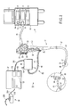
- FIG. 1 is a perspective view schematically showing an endoscope apparatus 1 included in the endoscope system.
- the endoscope apparatus 1 is composed of an electronic endoscope (endoscope main body) 2 and a peripheral device (device main body) of the endoscope 2.
- the peripheral device includes a light source unit 3 for creating endoscope illumination light, an image processing unit 4 for subjecting an image picked up by an image pickup portion (not shown) in the endoscope 2 to various types of image processing, an image display unit (for example, monitor) 5 for displaying an image, image data (the image processed by the image processing unit 4), a state of the device, an instruction of an operator, and the like, a controller 6 for overall control of the endoscope system and executing an arithmetic operation and the like, an input unit 7 having a keyboard and the like, a waste fluid tank 8 with a suction pump, a water feed tank 9, and the like.
- the peripheral device is mounted on a trolley 10.
- the light source unit 3 has a connection port 11 connected to a connector unit 16 and a display 12 for displaying an operating state of the light source unit 3 on the front surface thereof.
- the image processing unit 4 has a connector receiver 14 connected to a connection cable 13 on a front surface thereof.
- a connecting unit 17 with a cap is disposed in the base end of the connection cable 13. Further, the connector unit 16 is disposed in the extreme end of a universal cord 15 of the endoscope 2. An electrical connection portion of the connector unit 16 is detachably connected to the connecting unit 17 with the cap.
- An image pickup signal obtained in the image pickup portion is sent to the image processing unit 4 through the connection cable 13 and converted to a video signal.
- the video signal is displayed on the image display unit 5 as an image picked up by the endoscope 2.
- the endoscope 2 is an electronic endoscope for picking up an endoscope image by an image pick-up portion (not shown image pick-up device) disposed in the extreme end of a later-described insertion portion 21, it may be, for example, a fiber endoscope using an image guide fiber.
- an optical image guided by the image guide fiber is picked up by a TV camera or the like.
- the endoscope 2 has a manipulation portion 20 and the insertion portion 21 as a base member.
- the universal cord 15 is connected to the manipulation portion 20.
- a grip portion 22 is disposed in the manipulation portion 20.
- the manipulation portion 20 is provided with various types of function manipulation members, such as an angle manipulation knob 23, an air/water feed manipulation button 24, a suction manipulation button 25, a gas supply manipulation button 26, and switches 27.
- the function manipulation members are disposed in portions nearer to a proximal end side than the position of the grip portion 22.
- an insertion port 28 of an insertion channel, into which a later-described surgical instrument 40 and the like are inserted, is disposed in a portion which is positioned nearer to an extreme end side than the position of the grip portion 22.
- the insertion portion 21 is composed of a flexible tube (soft portion) 31 positioned to the proximal end side, a bending portion 32 connecting to the extreme end of the flexible tube 31, and an extreme end portion 33 connected to the extreme end of the bending portion 32.
- the flexible tube 31 has elasticity and flexibility and is bent by an external force.
- the bending portion 32 is forcibly bend by manipulating the angle manipulation knob 23.
- the position and the direction of the extreme end portion 33 are changed by bending the bending portion 32 so that a desired observation target (affected area and the like) is captured in an observation field of view (or in an image pickup field of view).
- an observation window 34, an illumination window 35, and a channel port 36 are disposed in the extreme end surface portion of the extreme end portion 33.
- An image pickup unit which includes an optical system composed of an objective lens (not shown) and the like and an image pick-up device such as a CCD, is disposed inside the observation window 34.
- the image pick-up unit picks up an affected area and the like in a body cavity.
- An image pick-up signal obtained by the image pick-up unit is sent to the image processing unit 4 through the connection cable 13 as described above.
- the channel port 36 communicates with the insertion port 28 through an insertion channel (not shown) formed in the insertion portion 21.
- the insertion channel is used as a path through which an insertion portion 42 of a multijointed surgical instrument 40 for an endoscope is inserted.
- one surgical instrument 40 is inserted into one insertion channel
- a plurality of surgical instruments 40 may be inserted into the one insertion channel.
- the surgical instrument extreme end movement controller 18 includes a surgical instrument controller 37, a surgical instrument drive unit (motor unit) 38, a bending manipulation unit (manipulation input unit) 39, and the surgical instrument 40.
- the surgical instrument 40 includes a manipulation unit 41 which can be gripped by an operator and the insertion portion 42 coupled with the manipulation unit 41.
- the surgical instrument drive unit 38 is assembled to the manipulation unit 41.
- the insertion portion 42 is inserted into a body cavity through the insertion channel.
- the insertion portion 42 is composed of a flexible tube (soft portion) 45 which is positioned on the proximal end (base end) side, a bending portion 46 connected to the extreme end of the flexible tube 45, and an extreme end portion 47 connected to the extreme end of the bending portion 46.
- the flexible tube 45 has elasticity and flexibility and is bent by an external force.
- the bending portion 46 is bent by the manipulation unit 41.
- the extreme end portion 47 is provided with a grip forceps 48 as a surgical instrument for operating on an affected area and the like.
- the grip forceps 48 includes grip members 48a, 48b which are opened and closed up and down.
- the grip members 48a, 48b are opened and closed in up and down directions by a manipulation wire 93 inserted into the insertion portion 42.
- the extreme end portion 47 may be provided with a surgical instrument such as a high-frequency knife or a high-frequency solidifier in addition to the grip forceps 48.
- the bending portion 46 includes the multijointed bending mechanism.
- the multijointed mechanism is constructed by coupling bending pieces 51, 52, 53, 54, 55.
- FIG. 4 is a perspective view showing the extreme end portion 47 and the bending portion 46.
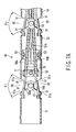
- FIG. 5A is a horizontal longitudinal sectional view of the bending portion 46 along line A-A in FIG. 4 in the long axis direction of the insertion portion 42 as viewed from above.
- FIG. 5B is a vertical longitudinal sectional view of the bending portion 46 along line B-B in FIG. 4 in the long axis direction of the insertion portion 42 as viewed from the left side thereof.
- the up, down, right, and left directions of the bending portion 46 are as shown by indexes of FIG. 4 .
- the bending pieces 51, 52, 53, 54, 55 are formed of an annular member. As shown in FIG. 4 , the bending pieces 51, 52, 53, 54, 55 are disposed by being coaxially arranged in a line in the long axis direction of the insertion portion 42.
- the bending pieces 51, 52, 53, 54, 55 are sequentially called a first bending piece 51, a second bending piece 52, a third bending piece 53, a fourth bending piece 54, and a fifth bending piece 55 from the extreme end side thereof.
- the first and second bending pieces 51, 52 are rotatably connected to each other around a first rotation shaft 61 and rotatably coupled with each other by the first rotation shaft 61.
- the axial direction of the first rotation shaft 61 is orthogonal to the long axis direction of the insertion portion 42 and the first rotation shaft 61 is disposed in a direction along the up and down directions shown in FIG. 4 . Accordingly, the first and second bending pieces 51, 52 can be relatively rotated in right and left directions when viewed from the proximal end (base end) side in FIG. 4 .
- the second and third bending pieces 52, 53 are rotatably connected to each other around a second rotation shaft 62 and rotatably coupled with each other by the second rotation shaft 62.
- the axial direction of the second rotation shaft 62 is orthogonal to the long axis direction of the insertion portion 42 and the second rotation shaft 62 is disposed in a direction along the right and left directions shown in FIG. 4 . Accordingly, the second and third bending pieces 52, 53 can be relatively rotated in the up and down directions when viewed from the proximal end (base end) side in FIG. 4 .
- the third and fourth bending pieces 53, 54 are rotatably connected to each other around a third rotation shaft 63 and rotatably coupled with each other by the third rotation shaft 63.
- the axial direction of the third rotation shaft 63 is orthogonal to the long axis direction of the insertion portion 42 and the third rotation shaft 63 is disposed in the direction along the up and down directions shown in FIG. 4 . Accordingly, the third and fourth bending pieces 53, 54 can be relatively rotated in the right and left directions when viewed from the proximal end (base end) side in FIG. 4 .
- the fourth and fifth bending pieces 54, 55 are rotatably connected to each other around a fourth rotation shaft 64 and rotatably coupled with each other by the fourth rotation shaft 64.
- the axial direction of the fourth rotation shaft 64 is orthogonal to the long axis direction of the insertion portion 42 and the fourth rotation shaft 64 is disposed in a direction along the right and left directions shown in FIG. 4 . Accordingly, the fourth and fifth bending pieces 54, 55 can be relatively rotated in the up and down directions when viewed from the proximal end (base end) side in FIG. 4 .
- the first rotation shaft 61 constitutes a joint for relatively rotating the first and second bending pieces 51, 52 in the right and left directions.
- the second rotation shaft 62 constitutes a joint for relatively rotating the second and third bending pieces 52, 53 in the up and down directions.
- the third rotation shaft 63 constitutes a joint for relatively rotating the third and fourth bending pieces 53, 54 in the right and left directions.
- the fourth rotation shaft 64 constitutes a joint for relatively rotating the fourth and fifth bending pieces 54, 55 in the up and down directions.
- the axial directions of the first, second, third, and fourth rotation shafts 61, 62, 63, 64 are alternately offset by 90°. That is, the bending pieces 51, 52 and the bending pieces 53, 54 are rotated in the right and left directions. The bending pieces 52, 53 and the bending pieces 54, 55 are rotated in the up and down directions. Further, the axial directions of the rotation shafts 61, 62, 63, 64 are orthogonal to the center axis (long axis) L of the bending portion 46 (refer to FIGS. 4 , 5A and 5B ). The center axis L agrees with the long axis of the insertion portion 42.
- the bending pieces 51, 52, 53, 54, 55 have tongue-piece-shaped coupling portions 65 projecting from the end edges thereof.
- the rotation shafts 61, 62, 63, 64 pass through the overlapping portions. That is, the rotation shafts 61, 62, 63, 64 are rivet-like shaft members.
- the multijointed bending mechanism arranged as described above is covered with a flexible casing (not shown).
- the bending portion 46 is constructed by this configuration.
- the manipulation wires 56a, 56b are laterally symmetrically disposed in the bending portion 46 with respect to the center axis L.
- the extreme ends of the manipulation wires 56a, 56b extend to the region in the first bending piece 51 and are connected to the first bending piece 51.
- the direction of the center axis of the first bending piece 51 approximately agrees with the direction of the center axis L.
- the right half portion of the first bending piece 51 is called a right portion
- the left half portion of the first bending piece 51 is called a left portion.
- the extreme end of the manipulation wire 56a described above is connected to the right portion of the first bending piece 51. Further, the extreme end of the manipulation wire 56b is connected to the left portion of the first bending piece 51.
- the manipulation wire 56a is pulled to the base end (proximal end) side shown in FIG. 5A , the first bending piece 51 is rotated rightward around the first rotation shaft 61. Further, when the manipulation wire 56b is pulled to the base end side, the first bending piece 51 is rotated leftward around the first rotation shaft 61. As described above, the manipulation wires 56 rotate the first bending piece 51.
- the manipulation wires 57a, 57b are vertically symmetrically disposed in the bending portion 46 with respect to the center axis L.
- the extreme ends of the manipulation wires 57a, 57b extend to the region in the second bending piece 52 and are connected to the second bending piece 52.
- the direction of the center axis of the second bending piece 52 approximately agrees with the direction of the center axis L.
- the upper half portion of the second bending piece 52 is called an upper portion
- the lower half portion of the second bending piece 52 is called a lower portion.
- the extreme end of the manipulation wire 57a described above is connected to the upper portion of the second bending piece 52. Further, the extreme end of the manipulation wire 57b is connected to the lower portion of the second bending piece 52.
- the manipulation wire 57a is pulled to the base end (proximal end) side shown in FIG. 5B
- the second bending piece 52 is rotated upward around the second rotation shaft 62.
- the manipulation wire 57b is pulled to the base end side shown in FIG. 5B
- the second bending piece 52 is rotated downward around the second rotation shaft 62.
- the manipulation wires 57 rotate the second bending piece 52.
- the manipulation wires 58a, 58b are laterally symmetrically disposed in the bending portion 46 with respect to the center axis L.
- the extreme ends of the manipulation wires 58a, 58b extend to the region in the third bending piece 53 and are connected to the third bending piece 53.
- the direction of the center axis of the third bending piece 53 approximately agrees with the direction of the center axis L.
- the right half portion of the third bending piece 53 is called a right portion
- the left half portion of the third bending piece 53 is called a left portion.
- the extreme end of the manipulation wire 58a described above is connected to the right portion of the third bending piece 53. Further, the extreme end of the manipulation wire 58b is connected to the left portion of the third bending piece 53.
- the manipulation wire 58a is pulled to the base end (proximal end) side shown in FIG. 5A
- the third bending piece 53 is rotated rightward around the third rotation shaft 63.
- the manipulation wire 58b is pulled to the base end side shown in FIG. 5A
- the third bending piece 53 is rotated leftward around the third rotation shaft 63.
- the manipulation wires 58 rotate the third bending piece 53.
- the manipulation wires 59a, 59b are vertically symmetrically disposed in the bending portion 46 with respect to the center axis L.
- the extreme ends of the manipulation wires 59a, 59b extend to the region in the fourth bending piece 54 and are connected to the fourth bending piece 54.
- the direction of the center axis of the fourth bending piece 54 approximately agrees with the direction of the center axis L.
- the upper half portion of the fourth bending piece 54 is called an upper portion
- the lower half portion of the fourth bending piece 54 is called a lower portion.
- the extreme end of the manipulation wire 59a described above is connected to the upper portion of the fourth bending piece 54. Further, the extreme end of the manipulation wire 59b is connected to the lower portion of the fourth bending piece 54.
- the fourth bending piece 54 is rotated upward around the fourth rotation shaft 64. Further, when the manipulation wire 59b is pulled to the base end side shown in FIG. 5B , the fourth bending piece 54 is rotated downward around the fourth rotation shaft 64. As described above, the manipulation wires 59 rotate the fourth bending piece 54.
- the pairs of the manipulation wires 56, 57, 58, 59 which individually correspond to each other, are connected to the bending pieces 51, 52, 53, 54.
- the pairs of the manipulation wires 56, 57, 58, 59 are appropriately selected and pushed and pulled in the bending portion 46, the bending pieces 51, 52, 53, 54 are independently rotated.
- cut and raised pieces 70 which project inside of the first bending piece 51, are formed in the right portion and the left portion of the first bending piece 51.
- the extreme end of the manipulation wire 56a is inserted into the cut and raised piece 70 in the right portion, and fixed to the cut and raised piece 70 by brazing.
- the extreme end of the manipulation wire 56b is inserted into the cut and raised piece 70 in the left portion, and fixed to the cut and raised piece 70 by brazing.
- cut and raised pieces 70 which project inside of the second bending piece 52, are formed in the upper portion and the lower portion of the second bending piece 52.
- the extreme end of the manipulation wire 57a is inserted into the cut and raised piece 70 in the upper portion, and fixed to the cut and raised piece 70 by brazing.
- the extreme end of the manipulation wire 57b is inserted into the cut and raised piece 70 in the lower portion, and fixed to the cut and raised piece 70 by brazing.
- cut and raised pieces 70 which project inside of the third bending piece 53, are formed in the right portion and the left portion of the third bending piece 53.
- the extreme end of the manipulation wire 58a is inserted into the cut and raised piece 70 in the right portion, and fixed to the cut and raised piece 70 by brazing.
- the extreme end of the manipulation wire 58b is inserted into the cut and raised piece 70 in the left portion, and fixed to the cut and raised piece 70 by brazing.
- cut and raised pieces 70 which project inside of the fourth bending piece 54, are formed in the upper portion and the lower portion of the fourth bending piece 54.
- the extreme end of the manipulation wire 59a is inserted into the cut and raised piece 70 in the upper portion, and fixed to the cut and raised piece 70 by brazing.
- the extreme end of the manipulation wire 59b is inserted into the cut and raised piece 70 in the lower portion, and fixed to the cut and raised piece 70 by brazing.
- the manipulation wires 56 are inserted into a guide sheath 66, the manipulation wires 57 are inserted into a guide sheath 67, the manipulation wires 58 are inserted into a guide sheath 68, and the manipulation wires 59 are inserted into a guide sheath 69, and they are individually guided up to the manipulation unit 41.
- the guide sheaths 66, 67, 68, 69 have flexibility and are formed of a sheath-like elastic member having elasticity; for example, an intimately wound coil, a resin tube, and the like. Inner holes of the guide sheaths 66, 67, 68, 69 act as guide members for guiding the direction of travel of the manipulation wires 56, 57, 58, 59.
- each guide sheath is not connected to a bending piece to which the manipulation wire to be guided by the guide sheath itself is connected but connected to a bending piece disposed nearer to the base end side than the above bending piece.
- the extreme ends of guide sheaths 66a, 66b are connected to the second bending piece 52.
- the extreme ends of guide sheaths 67a, 67b are connected to the third bending piece 53.
- the extreme ends of guide sheaths 68a, 68b are connected to the fourth bending piece 54.
- base ends of the guide sheaths may be connected to the base end portion of the bending portion 46 (the extreme end of the flexible tube 45).
- the most extreme end faces of the guide sheaths 66a, 66b may have slant surfaces whose sides near the center of the bending portion 46 retreat to the base end side than the side thereof near the outer periphery of the bending portion 46.
- the guide sheaths 66a, 66b may be arranged so that they avoid interference with contained members.
- a bending piece, to which the extreme end of a guide sheath is connected is not a bending piece to which a manipulation wire to be guided by the guide sheath is connected but a bending piece disposed nearer to the base end side than the bending piece to which the manipulation wire is connected. Accordingly, an extreme end of a manipulation wire projecting from the extreme end of a guide sheath is connected to the cut and raised piece 70 disposed in a bending piece disposed in the extreme end of a bending piece to which the extreme end of the guide sheath is connected. That is, the manipulation wires are guided up to the bending pieces which are disposed nearer to the base end side than the bending pieces to which they are connected by being caused to pass in the guide sheaths. Accordingly, a manipulation wire guided by a guide sheath does not directly contact the contained members such as other manipulation wires or guide sheaths so as to avoid interference therewith.
- the extreme ends of the guide sheaths 66a, 66b are fixed to a first wire guide 71 disposed in the second bending piece 52 and positioned to and supported by the second bending piece 52.
- the first wire guide 71 is formed of, for example, a sheet-shaped member as shown in FIGS. 5A , 5B and 6A .
- the first wire guide 71 is fixed to the inner wall of the second bending piece 52 by pins 60 at both the end edges thereof.
- An insertion hole 76 through which the contained members such as the guide sheaths 66a, 66b are inserted, is formed in a central portion of the first wire guide 71.
- the insertion hole 76 is formed in a circular shape around the center axis L.
- the extreme ends of the guide sheaths 66a, 66b are positioned and disposed in, for example, the right/left inner wall portions in the insertion hole 76, respectively and fixed to the portions by brazing or the like. Accordingly, the extreme ends of the guide sheaths 66a, 66b are disposed the same distance away from the center axis L. As described above, since the extreme ends of the guide sheaths 66a, 66b are disposed in the insertion hole 76, the extreme ends of the guide sheaths 66a, 66b are disposed in a region near the center in the bending portion 46.
- the manipulation wires 56a, 56b which are guided by the guide sheaths 66a, 66b, are also positioned in a region near the center in the bending portion 46. That is, the first wire guide 71 plays a role as positioning/disposing means for positioning and disposing the guide sheaths 66a, 66b.
- manipulation wires 56a, 56b project from the extreme ends of the guide sheaths 66a, 66b as shown in FIG. 5A , they enter the first bending piece 51 while extending, for example, right and left.
- the manipulation wire 56a is inserted into the cut and raised piece 70 in the right portion as described above.
- the manipulation wire 56b is inserted into the cut and raised piece 70 in the left portion as described above.
- the extreme ends of the guide sheaths 66a, 66b are directly fixed to the first wire guide 71, they may be indirectly fixed to the first wire guide 71 using a connector such as a connecting ring, not shown.
- the extreme ends of the guide sheaths 67a, 67b are fixed to a second wire guide 72 disposed in the third bending piece 53 and positioned and supported thereby.
- the second wire guide 72 is formed of, for example, a sheet-shaped member.
- the second wire guide 72 is fixed to the inner wall of the third bending piece 53 at both the end edges thereof by pins 60.
- the insertion hole 77 is formed in a circular shape around the center axis L.
- the diameter of the insertion hole 77 is larger than that of the insertion hole 76.
- the extreme ends of the guide sheaths 67a, 67b are positioned and disposed in, for example, upper and lower inner wall portions in the insertion hole 77 and fixed to the portions by brazing or the like, respectively. Accordingly, the extreme ends of the guide sheaths 67a, 67b are disposed the same distance away from the center axis L. Further, the guide sheaths 67a, 67b are disposed further away from the center axis L than the guide sheaths 66a, 66b.
- the guide sheaths 66a, 66b are disposed in a region nearer to a central portion in the bending portion 46 than the guide sheaths 67a, 67b. That is, the second wire guide 72 plays a role as positioning/disposing means for positioning and disposing the guide sheaths 67a, 67b.
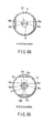
- the diameter of the insertion hole 77 is larger than that of the insertion hole 76, and the extreme ends of the guide sheaths 67a, 67b are disposed nearer to the inner wall of the insertion hole 77. Accordingly, as shown in FIG. 6B , the guide sheaths 67a, 67b are disposed further away from the center axis L than the guide sheaths 66a, 66b. In the second bending piece 52, the guide sheaths 66a, 66b are disposed and positioned by the first wire guide 71 so that they are disposed nearer to the center of the second bending piece 53 with respect to a direction vertical to the axial direction of the first rotation shaft 61.
- the guide sheaths 66a, 66b are guided to the third bending piece 53 in the above positional state. Therefore, the guide sheaths 66a, 66b are disposed inwards of the guide sheaths 67a, 67b in the third bending piece 53 with respect to a direction vertical to the axial direction of the second rotation shaft 62. That is, the guide sheaths 66a, 66b are disposed inwards of the guide sheaths 67a, 67b with respect to a direction vertical to the axial direction of the first and second rotation shafts 61, 62 (the direction of center axis L). Accordingly, the manipulation wires 56a, 56b are disposed inwards of the manipulation wires 57a, 57b in the direction of the center axis L.
- manipulation wires 57a, 57b which are guided by the guide sheaths 67a, 67b, project from the extreme ends of the guide sheaths 67a, 67b as shown in FIG. 5B , they enter the second bending piece 52 while extending, for example, up and down.
- the manipulation wire 57a is inserted into the cut and raised piece 70 in the upper portion as described above.
- the manipulation wire 57b is inserted into the cut and raised piece 70 in the lower portion as described above.
- the extreme ends of the guide sheaths 67a, 67b are directly fixed to the second wire guide 72, they may be indirectly fixed to the second wire guide 72 using a connector such as a connecting ring, not shown.
- the insertion hole 77 is formed in a circular shape, and the guide sheaths 66a, 66b are disposed nearer to the center axis L than the guide sheaths 67a, 67b. Accordingly, disposition of the guide sheaths 66a, 66b near the center axis L may result in formation of the right/left wall portions of the insertion hole 77 near the center axis L.
- the insertion hole 77 is formed not in a perfectly circular shape but in an oval shape which is longer in up and down directions. Accordingly, the right/left wall portions of the insertion hole 77 position and dispose the guide sheaths 66a, 66b inwards of the guide sheaths 67a, 67b.
- the second wire guide 72 exhibits an effect as positioning/disposing means for positioning the guide sheaths 66a, 66b inwards of the guide sheaths 67a, 67b (positioning the manipulation wires 56a, 56b inwards of the manipulation wires 57a, 57b).
- the extreme ends of the guide sheaths 67a, 67b are positioned and disposed in the upper/lower wall portions in the insertion hole 77.
- the guide sheaths 66a, 66b pass through the right/left regions of the insertion hole 77 in a state that they are not fixed to the second wire guide 72. Further, the guide sheaths 66a, 66b enter the insertion hole 77 after being regulated by the first wire guide 72. Accordingly, the guide sheaths 66a, 66b are disposed nearer to the inside of the central portion of the bending portion than the guide sheaths 67a, 67b.
- the third wire guide 73 is fixed to the fourth bending piece 54 and positioned and supported thereby.
- the third wire guide 73 is formed of a sheet-shaped member.
- the third wire guide 73 is fixed to the inner wall of the fourth bending piece 54 at both the end edges thereof by pins 60.
- the right/left portions of the third wire guide 73 are eliminated so that the third wire guide 73 is away from the inner wall of the fourth bending piece 54.
- Spaces 78a, 78b are formed in the eliminated portions to position and dispose the extreme ends of the guide sheaths 68a, 68b.
- the spaces 78a, 78b play a role as positioning/disposing means for positioning and disposing the extreme ends of the guide sheaths 68a, 68b.
- the extreme ends of the guide sheaths 68a, 68b are connected to, for example, the inner wall of the fourth bending piece 54 in the spaces 78a, 78b.
- a cut and raised piece 81a which projects inside of the fourth bending piece 54, is formed in the right inner wall of the fourth bending piece 54.
- a cut and raised piece 81b which projects inside of the fourth bending piece 54, is formed in the left inner wall of the fourth bending piece 54.
- the extreme end of the guide sheath 68a is inserted into the cut and raised piece 81a and fixed thereto by brazing.
- the extreme end of the guide sheath 68b is inserted into the cut and raised piece 81b and fixed thereto by brazing.
- the portion other than the extreme end (for example, the intermediate end) of the guide sheath 68a is fixed to the right inner wall of the third wire guide 73
- the portion other than the extreme end (for example, the intermediate end) of the guide sheath 68b is fixed to the left inner wall of the third wire guide 73.
- the extreme ends of the guide sheaths 68a, 68b may be fixed to the third wire guide 73 as shown in FIG. 5A .
- the extreme ends of the guide sheaths 68a, 68b are directly fixed to the fourth bending piece 54 or to the third wire guide 73, they may be indirectly connected to the fourth bending piece 54 or to the third wire guide 73 using a connector such as a connection ring, not shown.
- an insertion hole 79 into which the contained members such as the guide sheaths 66a, 66b, 67a, 67b are inserted, is formed in the central portion of the third wire guide 73.
- the insertion hole 79 is formed in a circular shape around the center axis L.
- the diameter of the insertion hole 79 is larger than the diameter of the insertion hole 76 and is the same as or larger than the diameter of the insertion hole 77.
- the guide sheaths 66a, 66b, which are previously positioned by the first wire guide 71, and the guide sheaths 67a, 67b, which are previously positioned by the second wire guide 72, are inserted into the insertion hole 79, respectively in the states in which they are positioned. That is, the third wire guide 73 gathers the guide sheaths 66a, 66b and the guide sheaths 67a, 67b near the central region of the bending portion 46.
- the guide sheaths 66a, 66b and the guide sheaths 67a, 67b are disposed inwards of the guide sheaths 68a, 68b with respect to a direction vertical to the axial direction of the first and second rotation shafts 61, 62 (the direction of the center axis L). That is, in the direction of the center axis L, the manipulation wires 56a, 56b and the manipulation wires 57a, 57b are disposed inwards of the manipulation wires 58a, 58b.
- the third wire guide 73 plays a role as positioning/disposing means for positioning the guide sheaths 66a, 66b and the guide sheaths 67a, 67b (the manipulation wires 56a, 56b and the manipulation wires 57a, 57b) inwards of the guide sheaths 68a, 68b (the manipulation wires 58a, 58b).
- the guide sheaths 66a, 66b are interposed between the guide sheath 68a and the guide sheath 68b as shown in FIGS. 6C and 6D . Further, the guide sheaths 66a, 66b and the guide sheaths 67a, 67b are disposed nearer to the central region in the vicinity of the center axis L than the guide sheaths 68a, 68b.
- the insertion hole 79 is formed in a circular shape, and the guide sheaths 66a, 66b are disposed nearer to the center axis L than the guide sheaths 67a, 67b. Accordingly, disposition of the guide sheaths 66a, 66b near the center axis L may result in formation of the right/left wall portions of the insertion hole 79 near the center axis L.
- the insertion hole 79 is formed not in a perfectly circular shape but in an oval shape which is longer in up and down directions. Accordingly, the right/left wall portions of the insertion hole 79 position and dispose the guide sheaths 66a, 66b inwards of the guide sheaths 67a, 67b. That is, the third wire guide 73 exhibits an effect of positioning the guide sheaths 66a, 66b.
- a fourth wire guide 74 is fixed to the fifth bending piece 55.
- the fourth wire guide 74 is formed of a sheet-shaped member like the wire guide 71 and the like.
- the fourth wire guide 74 is fixed to the inner wall of the fifth bending piece 55 at both the end edges thereof by pins 60.
- the right/left portions of the fourth wire guide 74 are eliminated so that the fourth wire guide 74 is away from the inner wall of the fifth bending piece 55.
- Spaces 78c, 78d, into which the guide sheaths 68a, 68b are inserted, are formed in the eliminated portions.
- the guide sheaths 68a, 68b are not fixed to the fourth wire guide 74 and pass through the spaces 78c, 78d in a state that they are positionally regulated by the third wire guide 73.
- the guide sheaths 68a, 68b are positionally regulated by the fourth wire guide 74 so that they are prevented from entering the center of the fifth bending piece 55.
- an insertion hole 80 into which the contained members such as the guide sheaths 66a, 66b and the guide sheaths 67a, 67b are inserted, is formed in the center of the fourth wire guide 74.
- the insertion hole 80 is formed in a circular shape around the center axis L.
- the diameter of the insertion hole 80 is larger than the diameter of the insertion hole 76 and is the same as or larger than the diameters of the insertion holes 77, 79.
- the guide sheaths 66a, 66b and the guide sheaths 67a, 67b are movably inserted into the insertion hole 80.
- the fourth wire guide 74 plays a role of gathering the guide sheaths 66a, 66b, 67a, 67b to the vicinity of the central region of the bending portion 46. That is, the fourth wire guide 74 also plays a role as positioning/disposing means of the guide sheaths 66a, 66b and the guide sheaths 67a, 67b.
- the guide sheaths 66a, 66b are interposed between the guide sheath 68a and the guide sheath 68b as shown in FIG. 6E .
- the guide sheaths 67a, 67b are interposed between the guide sheath 69a and the guide sheath 69b.
- the guide sheaths 66a, 66b and the guide sheaths 67a, 67b are disposed nearer to the central region in the vicinity of the center axis L than the guide sheaths 68a, 68b and the guide sheaths 69a, 69b.
- the insertion hole 80 is formed in a circular shape, and the guide sheaths 66a, 66b are disposed nearer to the center axis L than the guide sheaths 67a, 67b. Accordingly, disposition of the guide sheaths 66a, 66b near the center axis L may result in formation of the right/left wall portions of the insertion hole 80 near the center axis L.
- the insertion hole 80 is formed not in a perfectly circular shape but in an oval shape which is longer in up and down directions. Accordingly, the right/left wall portions of the insertion hole 80 position and dispose the guide sheaths 66a, 66b inwards of the guide sheaths 67a, 67b. That is, the fourth wire guide 74 exhibits an effect of positioning the guide sheaths 66a, 66b.
- a pair of fixing holes 82 are formed in both the upper/lower ends of the fourth wire guide 74.
- the fixing holes 82a, 82b are disposed vertically symmetrically with respect to the insertion hole 80.
- the fixing hole 82a is disposed above the insertion hole 80, and the fixing hole 82b is disposed below the insertion hole 80.
- the fixing holes 82a, 82b are disposed outwards of the guide sheaths 68a, 68b. That is, the fixing holes 82a, 82b are disposed further away from the center axis L than the guide sheaths 68a, 68b.
- the extreme end of the guide sheath 69a is inserted into the fixing hole 82a and fixed thereto by, for example, brazing.
- the extreme end of the guide sheath 69b is inserted into the fixing hole 82b and fixed thereto by, for example, brazing. Accordingly, as shown in FIG. 6E , the extreme ends of the guide sheaths 69a, 69b are disposed near the inner wall of the fifth bending piece 55 as well as outwards of the guide sheaths 68a, 68b.
- the guide sheaths 68a, 68b are disposed inwards of the guide sheaths 69a, 69b with respect to a direction vertical to the axial direction of the third and fourth rotation shafts 63, 64 (in the direction of the center axis L).
- the manipulation wires 58a, 58b are disposed inwards of the manipulation wires 59a, 59b.
- the guide sheaths 66a, 66b and the guide sheaths 67a, 67b are disposed inwards of the guide sheaths 68a, 68b and the guide sheaths 69a, 69b.
- the manipulation wires 56a, 56b and the manipulation wires 57a, 57b are disposed inwards of the manipulation wires 58a, 58b and the manipulation wires 59a, 59b.
- the fourth wire guide 74 plays a role as positioning/disposing means for positioning the guide sheaths 66a, 66b, the guide sheaths 67a, 67b, and the guide sheaths 68a, 68b (the manipulation wires 56a, 56b, the manipulation wires 57a, 57b, and the manipulation wires 58a, 58b) inwards of the guide sheaths 69a, 69b (the manipulation wires 59a, 59b).
- the wire guides play the role of the positioning/disposing means for specifying the positions of the guide sheaths and at the same time play the role as the positioning/disposing means for determining the positions of the manipulation wires which are individually guided by the guide sheaths. Since the positions of the guide sheaths are determined in the bending portion 46, the contained members including the guide sheaths are prevented from interfering with each other. Further, the manipulation wires inserted into the guide sheaths are prevented from being in direct contact with the other manipulation wires and the contained members thanks to the guide sheaths. Accordingly, interference between the manipulation wires and between the manipulation wires and the contained members is reduced.
- a first guide sheath group of the guide sheaths 66a, 66b and the guide sheaths 67a, 67b is positioned inwards of a second guide sheath group of the guide sheaths 68a, 68b and gathered to the central region of the bending portion 46 positioned inwards of the second guide sheath group.
- the guide sheaths 66a, 66b and the guide sheaths 68a, 68b are positioned on the same radius line passing through the center axis L and overlap inside and outside on the radius line.
- the first guide sheath group of the guide sheaths 66a, 66b and the guide sheaths 67a, 67b are positioned inwards of a second guide sheath group of the guide sheaths 68a, 68b and the guide sheaths 69a, 69b and gathered to the central region of the bending portion 46 positioned inwards of the second guide sheath group.
- the guide sheaths 66a, 66b and the guide sheaths 68a, 68b are positioned on the same radius line passing through the center axis L and positioned inside and outside on the radius line.
- the guide sheaths 67a, 67b and the guide sheaths 69a, 69b are positioned on the same radius line passing through the center axis L and overlap inside and outside on the radius line.
- the fifth bending piece 55 is a bending piece positioned at the most extreme base end of the bending portion 46. That is, it is possible to assume that the fifth bending piece 55 is the base end portion of the bending portion 46.
- a connector member 94 such as a connection ring is disposed in the extreme end of the flexible tube 45.
- the fifth bending piece 55 is coupled with the connector member 94. Further, the fifth bending piece 55 may be rotatably coupled with the connector member 94. In this mode, it is also possible to assume that the connector member 94 is the base end portion of the bending portion 46.
- the end faces 91 which confront each other (which are adjacent to each other) in adjacent bending pieces, form a gap 90.
- the gap 90 expands in a fan-shape at an angle ⁇ around the axis of a rotation shaft.
- lines extending from the end faces 91 intersect on the axis of the rotation shaft. Accordingly, the respective end faces 91 are formed as linear end edges passing through the rotation axis, respectively. Then, the gap 90 is formed by the two end faces 91 confronting each other and expanding in a fan-shape at an angle ⁇ about an intersecting point (axis of the rotation shaft).
- the extended lines need not necessarily intersect on the axis of the rotation shaft, and the respective end faces 91 may not be formed as linear end edges passing through the rotation axis, respectively.
- the gap 90 which expands in a fan-shape at the angle ⁇ , may be preferably formed by the lines which pass through ends (apexes) 91a, which are positioned at the most external sides of the end faces 91, and the axis of the rotation shaft.
- the sum of the angles ⁇ of the gaps 90 of at least two adjacent bending pieces in the bending pieces rotating in the same direction is set to 90° or more.
- the sum of the rotatable angle ⁇ 1 of the gap 90 between the bending pieces 51, 52 rotating in the same direction and the rotatable angle ⁇ 2 of the gap 90 between the bending pieces 53, 54 rotating in the same direction is set to 90° or more.
- the rotatable angle ⁇ of the multijointed bending piece may be preferably allocated not only to one gap 90 but also to the gaps 90 between the bending pieces rotating in the same direction (a plurality of adjacent gaps 90).
- the maximum angle ⁇ formed by one gap 90 is reduced.
- the amount of rotation of a bending piece in one gap 90 is reduced.
- the manipulation unit 41 is provided with a bending portion manipulation mechanism and a surgical portion manipulation mechanism.
- the bending portion manipulation mechanism is provided with drive motors 95, 96, 97, 98 for pushing and pulling the manipulation wires 56, 57, 58, 59, respectively.
- the surgical portion manipulation mechanism is provided with a drive motor 100 for pushing and pulling the manipulation wire 93.
- the manipulation wires 56, 57, 58, 59 correspond to the bending pieces (targets to be rotated) 51, 52, 53, 54 and execute rotating manipulations.
- the manipulation wire 93 manipulates the grip forceps 48.
- Pulleys 99 are attached to drive shafts of the drive motors 95, 96, 97, 98, 100, respectively.
- the respective drive shafts may be coupled with the respective pulleys 99 through reducers (not shown).
- the manipulation wires 56, 57, 58, 59, 93 are trained round the respective pulleys 99.
- the drive motors 95, 96, 97, 98, 100 are individually driven, respectively, and when the pulleys 99 are rotated, the manipulation wires 56, 57, 58, 59, 93 trained around the pulleys 99 are pushed and pulled.
- the bending portion manipulation mechanism and the surgical portion manipulation mechanism use transmission mechanisms making use of the pulleys 99, they may use, for example, a gear mechanism and the like making use of a pinion gear and a rack. Further, the bending portion manipulation mechanism and the surgical portion manipulation mechanism may use other types of drive actuators in place of the drive motors 95, 96, 97, 98, 100.
- the manipulation unit 41 is connected to the surgical instrument controller 37 through a cable 201.
- the bending manipulation unit 39 as the manipulation input unit is connected to the surgical instrument controller 37 through a cable 204.
- the surgical instrument controller 37 is provided with a power supply cord 205.
- the bending manipulation unit 39 includes a joystick (manipulation input unit) 203 for instructing a position and an attitude of the surgical instrument 40.
- the joystick 203 includes four joystick switches 203a, 203b, 203c, 203d continuously connected in four stages.
- the joystick switches 203a, 203b, 203c, 203d are attached to a manipulation box 210.
- the drive motors 95, 96, 97, 98 are individually driven corresponding to the manipulation.
- the bending pieces 51, 52, 53, 54 are individually and independently driven in up, down, right, and left directions to thereby bend respective joint portions.
- the surgical instrument extreme end movement controller 18 can move the extreme end portion 47 to a desired position by the movement according to the manipulation of the joystick 203. That is, the surgical instrument extreme end movement controller 18 constitutes the surgical instrument 40 which is arranged as a master/slave type and driven electrically. Note that, when the joystick 203 is manipulated by an operator and the like after a control for moving the surgical instrument 40 is set, preference is given to an instruction for manipulating the joystick 203.
- the surgical instrument controller 37 is provided with a function control input portion 121 for inputting an instruction output from the joystick 203, a condition for controlling the function of the joystick 203, and the like, a motor driver (surgical instrument drive controller) 122 for controlling the drive of the drive motors 95, 96, 97, 98, and a motor unit communication unit 123 connected to the surgical instrument drive unit 38 through the cable 201 for executing communication with the surgical instrument drive unit 38.
- a function control input portion 121 for inputting an instruction output from the joystick 203, a condition for controlling the function of the joystick 203, and the like
- a motor driver (surgical instrument drive controller) 122 for controlling the drive of the drive motors 95, 96, 97, 98
- a motor unit communication unit 123 connected to the surgical instrument drive unit 38 through the cable 201 for executing communication with the surgical instrument drive unit 38.
- the surgical instrument controller 37 transmits a control signal for driving the drive motors 95, 96, 97, 98 in response to the manipulation of the joystick 203 executed by the operator to the motor driver 122 and rotates the drive motors 95, 96, 97, 98.
- Encoders (not shown) are mounted on the drive motors 95, 96, 97, 98 to measure the number of revolutions thereof. The encoders feedback-control the drive motors 95, 96, 97, 98 by generating signals according to the number of revolutions and transmitting the signals to the motor driver 122.
- the joints disposed from the manipulation unit side (base end side) to the extreme end side are sequentially referred to as J1, J2, J3, J4.
- a coordinate system is set using the joint J1 disposed nearest to the manipulation unit side as a reference.
- a Y-axis direction agrees with a vertical direction of the image pickup device. It is assumed that the joints J1, J3 are bent about an X-axis, and the joints J2, J4 are bent about a Y-axis.
- the joystick 203 (manipulation input unit) includes joints J1', J2', J3', J4' which have the same structures as those of the joint J1 and the joints J2, J3, J4 located nearer to the extreme end side than the joint J1.
- the number of the joints and the bending directions of the joystick 203 are the same as those of the bending portion 46.
- the lengths of respective rods of the joystick 203 are set to values multiplied by an appropriate coefficient k so that the operator can easily manipulate them.
- k 10 and the length of each rod of the surgical instrument 40 is 3 mm
- the length of each rod of the joystick 203 (manipulation input unit) is set to 30 mm.
- Encoders (not shown) are assembled to the joints J1', J2', J3', J4' to measure bent angles. The information of the bent angles measured by the encoders is sent to the surgical instrument controller 37.
- the surgical instrument controller 37 generates drive signals corresponding to the angle information (the joints J1', J2', J3', J4') and bends the joints J1, J2, J3, J4 by rotating the drive motors 95, 96, 97, 98, respectively.
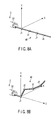
- the joints J1', J2', J3', J4' are bent as shown in, for example, FIG. 9
- the joints J1, J2, J3, J4 are bent as shown in FIG. 8B .
- the extreme end of the surgical instrument 40 can be moved to an arbitrary position and an arbitrary attitude so that an affected area can be more easily cut out and exfoliated than ever before. Further, since the joint structure of the surgical instrument 40 is caused to equally correspond to that of the manipulation input unit, the operator can easily operate the surgical instrument having a plurality of joints.
- the drive motor 100 also has a motor driver, a motor unit communication unit, and the like similarly to the drive motors 95, 96, 97, 98.
- the grip forceps 48 is manipulated by manipulating a manipulation body such as a handle (function control/input unit) 125 disposed in the manipulation unit 41 and the like.
- the manipulation input unit may be preferably provided with a first manipulation switch corresponding to the first bending piece 51, a second manipulation switch corresponding to the second bending piece 52, a third manipulation switch corresponding to the third bending piece 53, and a fourth manipulation switch corresponding to the fourth bending piece 54.
- the first manipulation switch When, for example, the first manipulation switch is depressed, the first bending piece 51 is bent.
- the manipulation unit 41 may be preferably provided with a switch device (manipulation switch) for the bending manipulation.
- the manipulation input unit may use a pen type input unit for inputting a three-dimensional position.
- the insertion portion 21 is inserted into a body cavity, and the insertion portion 42 is inserted from the insertion port 28 into the insertion channel in this state.
- the extreme end portion 47 and the bending portion 46 project from the channel port 36 into the body cavity.
- a work for gripping an affected area and the like in the body cavity is executed using the grip forceps 48 while observing them by the endoscope 2.
- the bending portion 46 can be bend to an appropriate multijointed bent shape according to the state in the body cavity and the surgical procedure. That is, when the joystick 203 is manipulated and the bending pieces 51, 52, 53, 54 are individually rotated, the bending portion 46 is bend into an appropriate shape.
- the manipulation wires 56a, 56b trained around the pulley 99 in the drive motor 95 are pushed and pulled.
- the first bending piece 51 is independently rotated.
- the manipulation wires 57a, 57b trained around the pulley 99 in the drive motor 96 are pushed and pulled.
- the second bending piece 52 is independently rotated.
- the manipulation wires 58a, 58b trained around the pulley 99 in the drive motor 97 are pushed and pulled.
- the third bending piece 53 is independently rotated.
- the fourth bending piece 54 is independently rotated.
- the bending pieces 51, 52, 53, 54 are independently rotated, and the bending portion 46 is bent.
- the bending portion 46 can even be bend in a complex shape by adjusting the direction in which the joystick 203 is rotated and the amount of rotation thereof.
- the manipulation wires are disposed in the plurality of bending pieces, an arbitrary bending piece can be independently rotated. Accordingly, in the embodiment, since the bending mechanism has a plurality of degrees of freedom, a work can be executed even in a narrow region such as a body cavity.
- the bending portion 46 can be partially bend also in a different direction.
- the bending portion 46 can be bend into an appropriate shape according to a state of use.
- the degree of freedom of bending of the bending portion 46 is increased, it is possible in the embodiment to easily execute even a complex work in a narrow body cavity region as compared with a case in which the bending portion 46 is uniformly bend.
- the attitude of the bending portion 46 can be easily bend so that it does not disturb another surgical instrument or observation with the endoscope 2, the workability of the surgical instrument 40 can be increased.
- the embodiment since the bending pieces 51, 52, 53, 54 can be independently bend, respectively, the joints of the bending pieces 51, 52, 53, 54 can be stably bend without being largely affected by the other bend portions. Accordingly, the embodiment can easily and securely execute a desired surgical with the surgical instrument 40.
- the manipulation wire connected to a bending piece disposed on the extreme end side is disposed inwards of the manipulation wire connected to a bending piece disposed on the base end side.
- the manipulation force of the manipulation wire connected to the bending piece disposed on the extreme end side and having a large frictional resistance due to the bending of the bending piece can be reduced. Accordingly, in the embodiment, since the manipulation force required by the manipulation wires can be reduced, made uniform, and stabilized, a manipulation can be smoothly executed by the manipulation wires.
- the manipulation wires 56a, 56b guided by the guide sheaths 66a, 66b are disposed nearer to the center of the bending portion 46 than the manipulation wires 57a, 57b guided by the guide sheaths 67a, 67b. Accordingly, when the bending pieces 51, 52, 53, 54 are bend, the frictional force which the manipulation wires 56a, 56b receive from the contained members becomes smaller than the frictional force which the manipulation wires 57a, 57b receive from the contained members. Accordingly, in the embodiment, the manipulation force required by the manipulation wires 56a, 56b can be reduced, made uniform, and stabilized, and the manipulation can be smoothly executed by the manipulation wires 56a, 56b.
- first and second wire guides 71, 72 dispose the manipulation wires 56a, 56b, the guide sheaths 66a, 66b, the manipulation wires 57a, 57b, and the guide sheaths 67a, 67b near the region of the central portion of the bending pieces 52, 53, 54, 55 (bending portion 46).
- the third and fourth wire guides 73, 74 dispose the manipulation wires 58a, 58b, the guide sheaths 68a, 68b, the manipulation wires 59a, 59b, and the guide sheaths 69a, 69b to the peripheral region in the bending pieces 52, 53, 54, 55 (bending portion 46).
- the manipulation wire for bending one bending piece disposed in the extreme end side and the guide sheath for guiding the manipulation wire are disposed more inwards of the bending portion 46 than the manipulation wire for bending the other bending piece disposed nearer to the base end side than the one bending piece and the guide sheath for guiding the manipulation wire.
- the embodiment can obtain the following operation/working effect.
- a manipulation wire for bending a bending piece disposed nearer to the extreme end side receives a larger frictional resistance from the contained members.
- the manipulation wire for bending the bending piece disposed in the extreme end side is disposed further inwards of the bending portion 46 than the manipulation wire for bending the bending piece disposed in the base end side as described above.
- the frictional resistance which the manipulation wire for bending the bending piece on the extreme end side receives is reduced.
- the manipulation force required by the manipulation wires can be reduced, made uniform, and stabilized, and the manipulation can be smoothly executed by the manipulation wires.
- the diameter of a bending mechanism portion can be easily reduced.
- the path of a manipulation wire for manipulating a bending piece located nearer to an extreme end side changes to a greater extent. Since the frictional resistance is increased by such change, the loss of manipulation force is increased. As a result, the manipulation force for manipulating the manipulation wire for bending the bending piece disposed on the extreme end side is increased.
- the manipulation wire for bending the bending piece disposed on the extreme end side is disposed in the region (in the vicinity of the central region in the bending portion 46) inwards of the manipulation wire for bending the bending piece disposed on the base end side.
- the embodiment can reduce the loss of the manipulation force by suppressing an increase of the frictional resistance of the manipulation wire on the extreme end side. Further, in the embodiment, since the path through which the manipulation wire passes is less changed even if the bending portion 46 is bend, a rotating manipulation can be executed lightly. Further, in the embodiment, when the bending portion 46 is bend, since a wasteful motion is suppressed, the change of the manipulation force can be also suppressed. Accordingly, the embodiment can securely transmit the manipulation force up to the bending piece on the extreme end side. Further, the embodiment can independently manipulate many bending pieces.
- many manipulation wires and many guide sheaths are disposed in the narrow bending portion 46.
- the embodiment can dispose the many manipulation wires and the many guide sheaths in the narrow bending portion 46 compactly by the positioning/disposing means. Accordingly, in the embodiment, the manipulation wires are less entangled in the bending portion 46 and the occurrence of interference of the manipulation wires with each other can be reduced.
- a guide sheath which guides a manipulation wire for rotating a bending piece, is connected to a bending piece located just behind the above bending piece (on the base end side).
- the embodiment can maximize the efficacy of the wire guide function achieved by the guide sheath. Further, the region in which the manipulation wires are separately exposed can be reduced. Accordingly, the embodiment can avoid any reduction in the wire guide functionality. Further, when, for example, the insertion portion 42 itself is twisted, the embodiment can alleviate the effect of the twist on the wire guide function of the guide sheaths.
- the guide sheaths may be formed of an intimately wound metal coil. With this configuration, the embodiment can sufficiently withstand any abrupt rotating and bending actions of the bending pieces.
- the embodiment uses the guide sheaths and disposes the guide sheaths at predetermined positions by use of the wire guides, it can also dispose the manipulation wires at the predetermined positions by use of the wire guides without using the guide sheaths.
- the embodiment can also directly position the manipulation wires in a state that the guide sheaths are omitted.
- the rotation shaft is not limited to the rivet-shaped portion and may be arranged as, for example, a pin-shaped portion, a locking portion for rotatably locking the bending pieces with each other, and the like.
- Wire guides 71, 72, 73, 74 are composed of a sheet-shaped member, and a plurality of lumens 111 are formed to the wire guides 71, 72, 73, 74.
- the wire guides 71, 72, 73, 74 position and dispose guide sheaths 66a, 66b, 67a, 67b, 69a, 69b by the lumens 111 and 112.
- a first wire guide 71 is disposed in a second bending piece 52.
- the four lumens 111 are formed on the top, bottom, right, and left of the center of the first wire guide 71.
- the right and left lumens 111 are disposed at the same distance from the center axis L.
- the upper and lower lumens 111 are disposed further away from the center axis L than the right and left lumens 111. Accordingly, the right and left lumens 111 are disposed nearer to the center axis L than the upper and lower lumens 111.
- the extreme ends of the guide sheaths 66a, 66b are inserted into the right and left lumens 111 and fixed thereto by brazing.
- the upper and lower lumens 111 are used as paths for guiding other contained members and the like from, for example, the upper and lower lumens 111 to an extreme end side.
- the upper and lower lumens 111 are used as paths for guiding the other contained members and the like to the central region.
- the second wire guide 72 is disposed in a third bending piece 53.
- the four lumens 111 are formed on the top, bottom, right, and left of the center of the second wire guide 72.
- the right and left lumens 111 are disposed in the same distance from the center axis L.
- the upper and lower lumens 111 are disposed further away from the center axis L than the right and left lumens 111. Accordingly, the right and left lumens 111 are disposed nearer to the center axis L than the upper and lower lumens 111.
- the guide sheaths 66a, 66b are inserted into the right and left lumens 111 so as to move forward and rearward therein.
- the extreme ends of the guide sheaths 67a, 67b are inserted into the upper and lower lumens 111 and fixed thereto by brazing.
- the distance from the guide sheaths 66a, 66b to the center axis L in the axial direction of the second rotation shaft 62 is smaller than that from the guide sheaths 67a, 67b to the center axis L in a direction vertical to the axial direction of the second rotation shaft 62. Accordingly, the guide sheaths 66a, 66b are disposed inwards of the guide sheaths 67a, 67b.
- the third wire guide 73 is disposed in a fourth bending piece 54.
- the four lumens 111 are formed on the top, bottom, right, and left of the center of the third wire guide 73.
- the four lumens 111 are disposed in the same manner as the lumens 111 disposed in the first wire guide 71 and the second wire guide 72.
- the guide sheaths 66a, 66b are inserted into the right and left lumens 111 so as to move forward and rearward therein.
- the guide sheaths 67a, 67b are inserted into the upper and lower lumens 111 so as to move forward and rearward therein.
- the extreme ends of the guide sheaths 68a, 68b are fixed to cut and raised pieces 81a, 81b, or the third wire guide 73 in spaces 78c, 78d as in the above embodiment.
- the fourth wire guide 74 is disposed in a fifth bending piece 55.
- the four lumens 111 are formed on the top, bottom, right, and left of the center of the fourth wire guide 74.
- the four lumens 111 are disposed in the same manner as the lumens 111 disposed in the third wire guide 73 described above.
- the guide sheaths 66a, 66b are inserted into the right and left lumens 111 so as to move forward and rearward therein.
- the guide sheaths 67a, 67b are inserted into the upper and lower lumens 111 so as to move forward and rearward therein.
- the guide sheaths 68a, 68b are inserted into the spaces 78c, 78d as in the above embodiment.
- the lumens 112 for attaching the extreme ends of the guide sheaths 69a, 69b are formed in the upper and lower end portions of the fourth wire guide 74.
- the distance from the lumens 112 to the center axis L is longer than the distance in a radius direction from the guide sheaths 68a, 68b to the center axis L. That is, the lumens 112 are disposed outwards of the guide sheaths 68a, 68b. Since the remaining configuration of the modification is approximately the same as that of the embodiment described above, the explanation thereof is omitted.
- the positions of the guide sheaths 66a, 66b, 67a, 67b, 69a, 69b are regulated by the lumens 111, 112. Accordingly, in the modification, since the manipulation wires 56a, 56b, 57a, 57b and the wire guides 71, 72, which are disposed in the vicinity of the center, can be simply attached to predetermined positions, they can be securely and accurately disposed.
- FIGS. 11A, 11B , 11C and 11D Next, another modification of the positioning/disposing means in the embodiment described above will be explained with reference to FIGS. 11A, 11B , 11C and 11D .
- the guide sheaths 66a, 66b, 67a, 67b are disposed in the central region of the bending portion 46 by the first wire guide 71 and the second wire guide 72. This is the same as the positioning/disposing means in the first embodiment.
- the third and fourth wire guides 73 and 74 are arranged as described below.
- Guide sheaths having flexibility are disposed in the third and fourth wire guides 73 and 74.
- lumens 111 for inserting the guide sheaths are formed to the third and fourth wire guides 73 and 74.
- the lumens are obliquely arranged to a sheet member for forming the wire guides. This point is different in respect of the embodiment described above.
- the guide sheaths 68a, 68b, 69a, 69b having flexibility are obliquely arranged by being offset by a predetermined angle, respectively in a peripheral region disposed outwards of the guide sheaths 66a, 66b, 67a, 67b disposed in an inner central region.
- the guide sheaths are not disposed up, down, right and left around the center axis L unlike the embodiment described above. Accordingly, in the modification, since the respective guide sheaths are obliquely disposed and the contained members are disposed compactly by making use of the narrow space in the bending portion 46, the diameter of the bending portion 46 can be reduced.
- guide sheaths are positioned without using wire guides as shown in FIGS. 11C and 11D , they may be disposed by the positioning/disposing means as described in the embodiment described above.
- FIGS. 12 and 13 The overall configuration of an endoscope apparatus system in this embodiment is approximately the same as that of the above-described embodiment.
- a motor unit of a surgical instrument 40 is additionally provided with a mechanism 131 for rotating a bending portion 46 around the axis of an insertion portion 42 and a mechanism 132 for advancing the bending portion 46 in the axial direction of the insertion portion 42 in parallel therewith.
- at least four joints are disposed in the bending portion 46.
- the movement of the surgical instrument 40 corresponds to that of a manipulation input unit 140.
- a joystick type manipulation input unit having an advancing, retreating, and rotating joint structure is used as the manipulation input unit 140.
- a coordinate system is set as shown in FIG. 12 .
- the coordinate system uses a base end portion 141 of the manipulation input unit 140 as a reference and corresponds to the surgical instrument 40.
- the joint J1 moves forward and rearward
- the joint J2 rotates in an axial direction
- the joints J3, J5 are bent about a Y-axis
- the joints J4, J6 are bent about an X-axis.
- the rotation angles of the joints J2 to J6 are shown by ⁇ 2 to ⁇ 6, respectively.
- the lengths of respective rods are shown by L1 to L5 and the length of an extreme end rod is shown by L6.
- the configuration of the surgical instrument 40 is different from that of the manipulation input unit 140. Accordingly, to operate the surgical instrument 40 by operating the manipulation input unit 140, it is necessary to match the position and the attitude of the surgical instrument 40 with those of the manipulation input unit 140. For this purpose, the rotation angles and the amounts of parallel (forward and rearward) movement of the respective joints of the surgical instrument 40 must be determined.
- the movement of the surgical instrument 40 corresponds to that of the manipulation input unit 140. Accordingly, the position and the attitude of the surgical instrument 40 are determined by those of the manipulation input unit 140. Assuming that the configuration of the surgical instrument 40 is known, the rotation angles and the amounts of parallel movement of the respective configurations of the surgical instrument 40 can be determined by inverse kinematics. Inverse kinematics is a method of estimating the specific values of the joints (angles and the like thereof) from the position/attitude information of the manipulator (surgical instrument 40) in a working space.
- Jacobian matrix J( ⁇ ) is determined by subjecting Ep to partial differentiation by the factor of ⁇ to determine ⁇ .
- J ⁇ / d ⁇ 1 dx ep / d ⁇ 2 dx ep ⁇ / d ⁇ n dx ep / d ⁇ 1 dy ep / d ⁇ 2 dy ep ⁇ / d ⁇ n dy ep / d ⁇ 1 dz ep / d ⁇ 2 dz ep ⁇ / d ⁇ n dz ep / d ⁇ 1 dRoll ep / d ⁇ 2 dRoll ep ⁇ / d ⁇ n dRoll ep / d ⁇ 1 dYaw ep / d ⁇ 2 dYaw ep ⁇ / d ⁇ n dYaw ep / d ⁇ 1
- the extreme end of the surgical instrument 40 can be moved to an arbitrary position and an arbitrary attitude from the position and the attitude of the manipulation input unit 140, and an affected area can be cut out and exfoliated more easily than ever before.
- the present invention can be also applied to a bending portion of an endoscope.
- the present invention can be applied to, for example, the bending mechanism of the bending portion in the insertion portion of the endoscope according to the embodiment described above.
- the surgical instrument as a target of the present invention also includes a surgical catheter.
Landscapes
- Health & Medical Sciences (AREA)
- Life Sciences & Earth Sciences (AREA)
- Surgery (AREA)
- Engineering & Computer Science (AREA)
- General Health & Medical Sciences (AREA)
- Veterinary Medicine (AREA)
- Public Health (AREA)
- Animal Behavior & Ethology (AREA)
- Nuclear Medicine, Radiotherapy & Molecular Imaging (AREA)
- Molecular Biology (AREA)
- Biomedical Technology (AREA)
- Heart & Thoracic Surgery (AREA)
- Medical Informatics (AREA)
- Robotics (AREA)
- Biophysics (AREA)
- Radiology & Medical Imaging (AREA)
- Physics & Mathematics (AREA)
- Pathology (AREA)
- Optics & Photonics (AREA)
- Ophthalmology & Optometry (AREA)
- Endoscopes (AREA)
- Instruments For Viewing The Inside Of Hollow Bodies (AREA)
- Surgical Instruments (AREA)
Abstract
Description
- The present invention relates to a multijointed bending mechanism in which a plurality of bending pieces can be independently manipulated by manipulation wires, and to a multijointed medical equipment having such multijointed bending mechanism.
- In general, an insertion portion of a piece of medical equipment such as an endoscope is provided with a bending portion. Bending pieces are rotatably coupled with each other in the bending portion. A manipulation wire is connected only to a bending piece at the most extreme end of the bending portion. The bending portion is bend in its entirety by pushing and pulling the manipulation wire. More specifically, since the respective bending pieces cannot be independently rotated, it is difficult for the bending pieces to take a predetermined bending state.
- To cope with the above problem, in
Patent Document 1, repellent force application means is disposed in the base end portion of a bending portion. When the bending portion is bend by a manipulation wire, the repellent force application means begins to bend the bending portion preferentially from the extreme end portion thereof. Further, inPatent Document 2, balloons are interposed between bending pieces, respectively. Rotation intervals between bending pieces are adjusted by the expansion and contraction of the balloons. With this configuration, when a bending portion is bend, the radius of bendature of the bending portion can be variably adjusted. - Patent Document 1: Jpn. Pat. Appln. KOKAI Publication No.
2003-126024 - Patent Document 2: Jpn. Pat. Appln. KOKAI Publication No.
06-105797 - When the bending state of the bending portion is regulated by the repellent force application means as disclosed in
Patent Document 1 or by the balloons as disclosed inPatent Document 2, only a part of the bending portion is preferentially bent. Accordingly, since it is impossible to selectively rotate an arbitrary bending piece, there is a possibility that a desired bending state cannot be attained. - When manipulation wires are disposed in respective bending pieces to increase the degree of freedom of the bending state, the number of the manipulation wires is increased. Accordingly, the number of the disposed manipulation wires is increased toward the extreme end side of the bending portion. As a result, a problem arises in that the degree of freedom of an operation is lowered on the extreme end side of the bending portion.
- Further, there is a possibility that the increase in the number of the manipulation wires makes it difficult for the manipulation wires to smoothly execute a bending manipulation. Further, the diameter of an equipment is increased in its entirety. This is particularly disadvantageous when it is desired to reduce the diameter of a medical equipment.
- Accordingly, the present invention provides a multijointed bending mechanism, in which only an arbitrary bending pieces can be independently rotated, a bending manipulation can be smoothly executed by manipulation wires, the manipulation wires are disposed compactly without being entangled with each other, and the diameter of a bending portion can be reduced, and multijointed medical equipment having the multijointed bending mechanism.
- According to one aspect of the present invention, there is provided a multijointed bending mechanism comprising: a first bending piece; a second bending piece connected to the first bending piece so as to be rotatable around a first rotation shaft; a third bending piece connected to the second bending piece so as to be rotatable around a second rotation shaft; at least two first wires connected to the first bending piece to rotate the first bending piece; and at least two second wires connected to the second bending piece to rotate the second bending piece, wherein the first wires are disposed inwards of the second wires with respect to a vertical direction of the first and second rotation shafts.
- According to one aspect of the present invention, there is provided a multijointed bending mechanism comprising: a first bending piece; a second bending piece connected to the first bending piece so as to be rotatable around a first rotation shaft; a third bending piece connected to the second bending piece so as to be rotatable around a second rotation shaft; at least two first wires connected to the first bending piece to rotate the first bending piece; and at least two third wires connected to the third bending piece to rotate the third bending piece, wherein the first wires are disposed inwards of the third wires with respect to a vertical direction of the first and second rotation shafts.
- An aspect of the present invention provides a multijointed medical equipment having the multijointed bending mechanism.
-
-
FIG. 1 is a perspective view schematically showing an endoscope apparatus included in an endoscope system according to an embodiment of the present invention. -
FIG. 2 is a perspective view schematically showing an endoscope and a surgical instrument in the endoscope system according to the embodiment. -
FIG. 3 is a perspective view schematically showing the surgical instrument according to the embodiment. -
FIG. 4 is a perspective view showing an extreme end portion and a bending portion in an insertion portion of the surgical instrument according to the embodiment. -
FIG. 5A is a horizontal longitudinal sectional view of the bending portion along line A-A inFIG. 4 in the long axis direction of the insertion portion, as viewed from above. -
FIG. 5B is a vertical longitudinal sectional view of the bending portion along line B-B inFIG. 4 in the long axis direction of the insertion portion, as viewed from the left side thereof. -
FIG. 6A is a lateral sectional view along a line A-A inFIG. 5B and a view showing the disposition of manipulation wires and guide sheaths. -
FIG. 6B is a lateral sectional view along a line B-B inFIG. 5B and a view showing the disposition of the manipulation wires and the guide sheaths. -
FIG. 6C is a lateral sectional view along a line C1-C1 inFIG. 5B and a view showing the disposition of the manipulation wires and the guide sheaths. -
FIG. 6D is a lateral sectional view along a line C2-C2 inFIG. 5B and a view showing the disposition of the manipulation wires and the guide sheaths. -
FIG. 6E is a lateral sectional view along a line D-D inFIG. 5B and a view showing the disposition of the manipulation wires and the guide sheaths. -
FIG. 7A shows the angular relationship under which bending pieces rotate and is a longitudinal sectional view of the bending portion from above. -
FIG. 7B shows the angular relationship under which the bending pieces rotate and is a longitudinal sectional view of the bending portion as viewed from above. -
FIG. 8A is an explanatory view of a multijointed structure in the bending portion of a surgical instrument. -
FIG. 8B is an explanatory view of a multijointed structure in the bending portion of the surgical instrument. -
FIG. 9 is an explanatory view of a multijointed structure in a joystick. -
FIG. 10A shows a modification of the disposition of wire guides and is a lateral sectional view along the line A-A inFIG. 5B when the wire guides are viewed from a front surface thereof. -
FIG. 10B shows a modification of the disposition of the wire guides and is a lateral sectional view along the line B-B inFIG. 5B when the wire guides are viewed from the front surface thereof. -
FIG. 10C shows a modification of the disposition of the wire guides and is a lateral sectional view along the line C1-C1 inFIG. 5B when the wire guides are viewed from the front surface thereof. -
FIG. 10D shows a modification of the disposition of the wire guides and is a lateral sectional view along the line C2-C2 inFIG. 5B from the front surface thereof. -
FIG. 10E shows a modification of the disposition of the wire guides and is a lateral sectional view along the line D-D inFIG. 5B when the wire guides are viewed from the front surface thereof. -
FIG. 11A shows a modification of the disposition of the wire guides and is a lateral sectional view along the line A-A inFIG. 5B when the wire guides are viewed from the front surface thereof. -
FIG. 11B shows a modification of the disposition of the wire guides and is a lateral sectional view along the line B-B inFIG. 5B when the wire guides are viewed from the front surface thereof. -
FIG. 11C shows a modification of the disposition of the wire guides and is a lateral sectional view along the line C2-C2 inFIG. 5B when the wire guides are viewed from the front surface thereof. -
FIG. 11D shows a modification of the disposition of the wire guides and is a lateral sectional view along the line D-D inFIG. 5B when the wire guides are viewed from the front surface thereof. -
FIG. 12 is an explanatory view of a multijointed structure in a bending portion of a surgical instrument in another embodiment of the present invention. -
FIG. 13 is an explanatory view of a multijointed structure of a joystick in the embodiment. - A multijointed surgical instrument (for example, multijointed medical equipment) having a multijointed bending mechanism according to an embodiment of the present invention and an endoscope system having such multijointed surgical instrument will be explained below with reference to the drawings.
-
FIG. 1 is a perspective view schematically showing anendoscope apparatus 1 included in the endoscope system. Theendoscope apparatus 1 is composed of an electronic endoscope (endoscope main body) 2 and a peripheral device (device main body) of theendoscope 2. - The peripheral device includes a
light source unit 3 for creating endoscope illumination light, animage processing unit 4 for subjecting an image picked up by an image pickup portion (not shown) in theendoscope 2 to various types of image processing, an image display unit (for example, monitor) 5 for displaying an image, image data (the image processed by the image processing unit 4), a state of the device, an instruction of an operator, and the like, acontroller 6 for overall control of the endoscope system and executing an arithmetic operation and the like, aninput unit 7 having a keyboard and the like, awaste fluid tank 8 with a suction pump, a water feed tank 9, and the like. The peripheral device is mounted on atrolley 10. - The
light source unit 3 has aconnection port 11 connected to aconnector unit 16 and adisplay 12 for displaying an operating state of thelight source unit 3 on the front surface thereof. - The
image processing unit 4 has aconnector receiver 14 connected to aconnection cable 13 on a front surface thereof. A connectingunit 17 with a cap is disposed in the base end of theconnection cable 13. Further, theconnector unit 16 is disposed in the extreme end of auniversal cord 15 of theendoscope 2. An electrical connection portion of theconnector unit 16 is detachably connected to the connectingunit 17 with the cap. - An image pickup signal obtained in the image pickup portion is sent to the
image processing unit 4 through theconnection cable 13 and converted to a video signal. The video signal is displayed on theimage display unit 5 as an image picked up by theendoscope 2. - Although the
endoscope 2 is an electronic endoscope for picking up an endoscope image by an image pick-up portion (not shown image pick-up device) disposed in the extreme end of a later-describedinsertion portion 21, it may be, for example, a fiber endoscope using an image guide fiber. When the fiber endoscope is used, an optical image guided by the image guide fiber is picked up by a TV camera or the like. - As shown in
FIGS. 1 and2 , theendoscope 2 has amanipulation portion 20 and theinsertion portion 21 as a base member. - The
universal cord 15 is connected to themanipulation portion 20. Agrip portion 22 is disposed in themanipulation portion 20. Themanipulation portion 20 is provided with various types of function manipulation members, such as anangle manipulation knob 23, an air/waterfeed manipulation button 24, asuction manipulation button 25, a gassupply manipulation button 26, and switches 27. The function manipulation members are disposed in portions nearer to a proximal end side than the position of thegrip portion 22. Further, aninsertion port 28 of an insertion channel, into which a later-describedsurgical instrument 40 and the like are inserted, is disposed in a portion which is positioned nearer to an extreme end side than the position of thegrip portion 22. - As shown in
FIGS. 1 and2 , theinsertion portion 21 is composed of a flexible tube (soft portion) 31 positioned to the proximal end side, a bendingportion 32 connecting to the extreme end of theflexible tube 31, and anextreme end portion 33 connected to the extreme end of the bendingportion 32. Theflexible tube 31 has elasticity and flexibility and is bent by an external force. The bendingportion 32 is forcibly bend by manipulating theangle manipulation knob 23. The position and the direction of theextreme end portion 33 are changed by bending the bendingportion 32 so that a desired observation target (affected area and the like) is captured in an observation field of view (or in an image pickup field of view). - As shown in
FIG. 2 , anobservation window 34, anillumination window 35, and achannel port 36 are disposed in the extreme end surface portion of theextreme end portion 33. - An image pickup unit, which includes an optical system composed of an objective lens (not shown) and the like and an image pick-up device such as a CCD, is disposed inside the
observation window 34. The image pick-up unit picks up an affected area and the like in a body cavity. An image pick-up signal obtained by the image pick-up unit is sent to theimage processing unit 4 through theconnection cable 13 as described above. - The
channel port 36 communicates with theinsertion port 28 through an insertion channel (not shown) formed in theinsertion portion 21. The insertion channel is used as a path through which aninsertion portion 42 of a multijointedsurgical instrument 40 for an endoscope is inserted. - Although it is assumed in the embodiment that one
surgical instrument 40 is inserted into one insertion channel, a plurality ofsurgical instruments 40 may be inserted into the one insertion channel. Further, it is also possible to provide a plurality of the insertion channels and to insert each of thesurgical instruments 40 into each of the insertion channels. - Next, a surgical instrument extreme
end movement controller 18 will be explained with reference toFIGS. 2 ,3 ,4 ,5A and5B . As shown inFIG. 2 , the surgical instrument extremeend movement controller 18 includes asurgical instrument controller 37, a surgical instrument drive unit (motor unit) 38, a bending manipulation unit (manipulation input unit) 39, and thesurgical instrument 40. - The
surgical instrument 40 includes amanipulation unit 41 which can be gripped by an operator and theinsertion portion 42 coupled with themanipulation unit 41. - The surgical
instrument drive unit 38 is assembled to themanipulation unit 41. - As shown in
FIG. 2 , theinsertion portion 42 is inserted into a body cavity through the insertion channel. Theinsertion portion 42 is composed of a flexible tube (soft portion) 45 which is positioned on the proximal end (base end) side, a bendingportion 46 connected to the extreme end of theflexible tube 45, and anextreme end portion 47 connected to the extreme end of the bendingportion 46. - The
flexible tube 45 has elasticity and flexibility and is bent by an external force. - The bending
portion 46 is bent by themanipulation unit 41. - The
extreme end portion 47 is provided with agrip forceps 48 as a surgical instrument for operating on an affected area and the like. - As shown in
FIG. 4 , thegrip forceps 48 includesgrip members grip members manipulation wire 93 inserted into theinsertion portion 42. Theextreme end portion 47 may be provided with a surgical instrument such as a high-frequency knife or a high-frequency solidifier in addition to thegrip forceps 48. - As shown in
FIGS. 4 ,5A and5B , the bendingportion 46 includes the multijointed bending mechanism. The multijointed mechanism is constructed by coupling bendingpieces FIG. 4 is a perspective view showing theextreme end portion 47 and the bendingportion 46.FIG. 5A is a horizontal longitudinal sectional view of the bendingportion 46 along line A-A inFIG. 4 in the long axis direction of theinsertion portion 42 as viewed from above.FIG. 5B is a vertical longitudinal sectional view of the bendingportion 46 along line B-B inFIG. 4 in the long axis direction of theinsertion portion 42 as viewed from the left side thereof. The up, down, right, and left directions of the bendingportion 46 are as shown by indexes ofFIG. 4 . - The bending
pieces FIG. 4 , the bendingpieces insertion portion 42. The bendingpieces first bending piece 51, asecond bending piece 52, athird bending piece 53, afourth bending piece 54, and afifth bending piece 55 from the extreme end side thereof. - The first and
second bending pieces first rotation shaft 61 and rotatably coupled with each other by thefirst rotation shaft 61. The axial direction of thefirst rotation shaft 61 is orthogonal to the long axis direction of theinsertion portion 42 and thefirst rotation shaft 61 is disposed in a direction along the up and down directions shown inFIG. 4 . Accordingly, the first andsecond bending pieces FIG. 4 . - The second and
third bending pieces second rotation shaft 62 and rotatably coupled with each other by thesecond rotation shaft 62. The axial direction of thesecond rotation shaft 62 is orthogonal to the long axis direction of theinsertion portion 42 and thesecond rotation shaft 62 is disposed in a direction along the right and left directions shown inFIG. 4 . Accordingly, the second andthird bending pieces FIG. 4 . - The third and
fourth bending pieces third rotation shaft 63 and rotatably coupled with each other by thethird rotation shaft 63. The axial direction of thethird rotation shaft 63 is orthogonal to the long axis direction of theinsertion portion 42 and thethird rotation shaft 63 is disposed in the direction along the up and down directions shown inFIG. 4 . Accordingly, the third andfourth bending pieces FIG. 4 . - The fourth and
fifth bending pieces fourth rotation shaft 64 and rotatably coupled with each other by thefourth rotation shaft 64. The axial direction of thefourth rotation shaft 64 is orthogonal to the long axis direction of theinsertion portion 42 and thefourth rotation shaft 64 is disposed in a direction along the right and left directions shown inFIG. 4 . Accordingly, the fourth andfifth bending pieces FIG. 4 . - That is, the
first rotation shaft 61 constitutes a joint for relatively rotating the first andsecond bending pieces second rotation shaft 62 constitutes a joint for relatively rotating the second andthird bending pieces third rotation shaft 63 constitutes a joint for relatively rotating the third andfourth bending pieces fourth rotation shaft 64 constitutes a joint for relatively rotating the fourth andfifth bending pieces - In the embodiment, the axial directions of the first, second, third, and
fourth rotation shafts pieces pieces pieces pieces rotation shafts FIGS. 4 ,5A and5B ). The center axis L agrees with the long axis of theinsertion portion 42. - As shown in
FIGS. 5A and5B , the bendingpieces coupling portions 65 projecting from the end edges thereof. When thecoupling portions 65 are overlapped with each other, therotation shafts rotation shafts - The multijointed bending mechanism arranged as described above is covered with a flexible casing (not shown). The bending
portion 46 is constructed by this configuration. - A first set of a pair of non-expandable manipulation wires 56 (56a, 56b) connected to the
first bending piece 51, a second set of a pair of non-expandable manipulation wires 57 (57a, 57b) connected to thesecond bending piece 52, a third set of a pair of non-expandable manipulation wires 58 (58a, 58b) connected to thethird bending piece 53, and a fourth set of a pair of non-expandable manipulation wires 59 (59a, 59b) connected to thefourth bending piece 54 are inserted into theinsertion portion 42. - As shown in
FIG. 5A , themanipulation wires portion 46 with respect to the center axis L. The extreme ends of themanipulation wires first bending piece 51 and are connected to thefirst bending piece 51. - The direction of the center axis of the
first bending piece 51 approximately agrees with the direction of the center axis L. On one plane which passes through both the direction of the center axis of thefirst bending piece 51 and the axial direction of thefirst rotation shaft 61, the right half portion of thefirst bending piece 51 is called a right portion, and the left half portion of thefirst bending piece 51 is called a left portion. - The extreme end of the
manipulation wire 56a described above is connected to the right portion of thefirst bending piece 51. Further, the extreme end of themanipulation wire 56b is connected to the left portion of thefirst bending piece 51. When themanipulation wire 56a is pulled to the base end (proximal end) side shown inFIG. 5A , thefirst bending piece 51 is rotated rightward around thefirst rotation shaft 61. Further, when themanipulation wire 56b is pulled to the base end side, thefirst bending piece 51 is rotated leftward around thefirst rotation shaft 61. As described above, themanipulation wires 56 rotate thefirst bending piece 51. - As shown in
FIG. 5B , themanipulation wires portion 46 with respect to the center axis L. The extreme ends of themanipulation wires second bending piece 52 and are connected to thesecond bending piece 52. - The direction of the center axis of the
second bending piece 52 approximately agrees with the direction of the center axis L. On one plane which passes through both the direction of the center axis of thesecond bending piece 52 and the axial direction of thesecond rotation shaft 62, the upper half portion of thesecond bending piece 52 is called an upper portion, and the lower half portion of thesecond bending piece 52 is called a lower portion. - The extreme end of the
manipulation wire 57a described above is connected to the upper portion of thesecond bending piece 52. Further, the extreme end of themanipulation wire 57b is connected to the lower portion of thesecond bending piece 52. When themanipulation wire 57a is pulled to the base end (proximal end) side shown inFIG. 5B , thesecond bending piece 52 is rotated upward around thesecond rotation shaft 62. Further, when themanipulation wire 57b is pulled to the base end side shown inFIG. 5B , thesecond bending piece 52 is rotated downward around thesecond rotation shaft 62. As described above, themanipulation wires 57 rotate thesecond bending piece 52. - As shown in
FIG. 5A , themanipulation wires portion 46 with respect to the center axis L. The extreme ends of themanipulation wires third bending piece 53 and are connected to thethird bending piece 53. - The direction of the center axis of the
third bending piece 53 approximately agrees with the direction of the center axis L. On one plane which passes through both the direction of the center axis of thethird bending piece 53 and the axial direction of thethird rotation shaft 63, the right half portion of thethird bending piece 53 is called a right portion, and the left half portion of thethird bending piece 53 is called a left portion. - The extreme end of the
manipulation wire 58a described above is connected to the right portion of thethird bending piece 53. Further, the extreme end of themanipulation wire 58b is connected to the left portion of thethird bending piece 53. When themanipulation wire 58a is pulled to the base end (proximal end) side shown inFIG. 5A , thethird bending piece 53 is rotated rightward around thethird rotation shaft 63. Further, when themanipulation wire 58b is pulled to the base end side shown inFIG. 5A , thethird bending piece 53 is rotated leftward around thethird rotation shaft 63. As described above, themanipulation wires 58 rotate thethird bending piece 53. - As shown in
FIG. 5B , themanipulation wires portion 46 with respect to the center axis L. The extreme ends of themanipulation wires fourth bending piece 54 and are connected to thefourth bending piece 54. - The direction of the center axis of the
fourth bending piece 54 approximately agrees with the direction of the center axis L. On one plane which passes through both the direction of the center axis of thefourth bending piece 54 and the axial direction of thefourth rotation shaft 64, the upper half portion of thefourth bending piece 54 is called an upper portion, and the lower half portion of thefourth bending piece 54 is called a lower portion. - The extreme end of the
manipulation wire 59a described above is connected to the upper portion of thefourth bending piece 54. Further, the extreme end of themanipulation wire 59b is connected to the lower portion of thefourth bending piece 54. When themanipulation wire 59a is pulled to the base end (proximal end) side shown inFIG. 5B , thefourth bending piece 54 is rotated upward around thefourth rotation shaft 64. Further, when themanipulation wire 59b is pulled to the base end side shown inFIG. 5B , thefourth bending piece 54 is rotated downward around thefourth rotation shaft 64. As described above, themanipulation wires 59 rotate thefourth bending piece 54. - As described above, the pairs of the
manipulation wires pieces manipulation wires portion 46, the bendingpieces - Various methods can be employed to connect the extreme ends of the
manipulation wires pieces - As shown in
FIG. 5A , in the base end portion of thefirst bending piece 51, cut and raisedpieces 70, which project inside of thefirst bending piece 51, are formed in the right portion and the left portion of thefirst bending piece 51. The extreme end of themanipulation wire 56a is inserted into the cut and raisedpiece 70 in the right portion, and fixed to the cut and raisedpiece 70 by brazing. Further, the extreme end of themanipulation wire 56b is inserted into the cut and raisedpiece 70 in the left portion, and fixed to the cut and raisedpiece 70 by brazing. - As shown in
FIG. 5B , in the base end portion of thesecond bending piece 52, cut and raisedpieces 70, which project inside of thesecond bending piece 52, are formed in the upper portion and the lower portion of thesecond bending piece 52. The extreme end of themanipulation wire 57a is inserted into the cut and raisedpiece 70 in the upper portion, and fixed to the cut and raisedpiece 70 by brazing. Further, the extreme end of themanipulation wire 57b is inserted into the cut and raisedpiece 70 in the lower portion, and fixed to the cut and raisedpiece 70 by brazing. - As shown in
FIG. 5A , in the periphery of the base end portion of thethird bending piece 53, cut and raisedpieces 70, which project inside of thethird bending piece 53, are formed in the right portion and the left portion of thethird bending piece 53. The extreme end of themanipulation wire 58a is inserted into the cut and raisedpiece 70 in the right portion, and fixed to the cut and raisedpiece 70 by brazing. Further, the extreme end of themanipulation wire 58b is inserted into the cut and raisedpiece 70 in the left portion, and fixed to the cut and raisedpiece 70 by brazing. - As shown in
FIG. 5B , in the base end portion of thefourth bending piece 54, cut and raisedpieces 70, which project inside of thefourth bending piece 54, are formed in the upper portion and the lower portion of thefourth bending piece 54. The extreme end of themanipulation wire 59a is inserted into the cut and raisedpiece 70 in the upper portion, and fixed to the cut and raisedpiece 70 by brazing. Further, the extreme end of themanipulation wire 59b is inserted into the cut and raisedpiece 70 in the lower portion, and fixed to the cut and raisedpiece 70 by brazing. - The
manipulation wires 56 are inserted into a guide sheath 66, themanipulation wires 57 are inserted into a guide sheath 67, themanipulation wires 58 are inserted into a guide sheath 68, and themanipulation wires 59 are inserted into a guide sheath 69, and they are individually guided up to themanipulation unit 41. The guide sheaths 66, 67, 68, 69 have flexibility and are formed of a sheath-like elastic member having elasticity; for example, an intimately wound coil, a resin tube, and the like. Inner holes of the guide sheaths 66, 67, 68, 69 act as guide members for guiding the direction of travel of themanipulation wires - The extreme end of each guide sheath is not connected to a bending piece to which the manipulation wire to be guided by the guide sheath itself is connected but connected to a bending piece disposed nearer to the base end side than the above bending piece. For example, the extreme ends of
guide sheaths second bending piece 52. The extreme ends ofguide sheaths third bending piece 53. Further, the extreme ends ofguide sheaths fourth bending piece 54. - Note that base ends of the guide sheaths may be connected to the base end portion of the bending portion 46 (the extreme end of the flexible tube 45). Further, as shown in
FIGS. 7A and7B , the most extreme end faces of theguide sheaths portion 46 retreat to the base end side than the side thereof near the outer periphery of the bendingportion 46. As described above, theguide sheaths - A bending piece, to which the extreme end of a guide sheath is connected, is not a bending piece to which a manipulation wire to be guided by the guide sheath is connected but a bending piece disposed nearer to the base end side than the bending piece to which the manipulation wire is connected. Accordingly, an extreme end of a manipulation wire projecting from the extreme end of a guide sheath is connected to the cut and raised
piece 70 disposed in a bending piece disposed in the extreme end of a bending piece to which the extreme end of the guide sheath is connected. That is, the manipulation wires are guided up to the bending pieces which are disposed nearer to the base end side than the bending pieces to which they are connected by being caused to pass in the guide sheaths. Accordingly, a manipulation wire guided by a guide sheath does not directly contact the contained members such as other manipulation wires or guide sheaths so as to avoid interference therewith. - Next, how the manipulation wires and the guide sheaths are disposed in the bending pieces will be explained with reference to
FIGS. 5A ,5B ,6A, 6B ,6C, 6D , and6E . - The extreme ends of the
guide sheaths first wire guide 71 disposed in thesecond bending piece 52 and positioned to and supported by thesecond bending piece 52. Thefirst wire guide 71 is formed of, for example, a sheet-shaped member as shown inFIGS. 5A ,5B and6A . Thefirst wire guide 71 is fixed to the inner wall of thesecond bending piece 52 bypins 60 at both the end edges thereof. Aninsertion hole 76, through which the contained members such as theguide sheaths first wire guide 71. Theinsertion hole 76 is formed in a circular shape around the center axis L. The extreme ends of theguide sheaths insertion hole 76, respectively and fixed to the portions by brazing or the like. Accordingly, the extreme ends of theguide sheaths guide sheaths insertion hole 76, the extreme ends of theguide sheaths portion 46. As a result, themanipulation wires guide sheaths portion 46. That is, thefirst wire guide 71 plays a role as positioning/disposing means for positioning and disposing theguide sheaths - After the
manipulation wires guide sheaths FIG. 5A , they enter thefirst bending piece 51 while extending, for example, right and left. Themanipulation wire 56a is inserted into the cut and raisedpiece 70 in the right portion as described above. Themanipulation wire 56b is inserted into the cut and raisedpiece 70 in the left portion as described above. - Note that although the extreme ends of the
guide sheaths first wire guide 71, they may be indirectly fixed to thefirst wire guide 71 using a connector such as a connecting ring, not shown. - As shown in
FIGS. 5A ,5B and6B , the extreme ends of theguide sheaths second wire guide 72 disposed in thethird bending piece 53 and positioned and supported thereby. Thesecond wire guide 72 is formed of, for example, a sheet-shaped member. Thesecond wire guide 72 is fixed to the inner wall of thethird bending piece 53 at both the end edges thereof by pins 60. Aninsertion hole 77, through which the contained members such as theguide sheaths second wire guide 72. Theinsertion hole 77 is formed in a circular shape around the center axis L. The diameter of theinsertion hole 77 is larger than that of theinsertion hole 76. The extreme ends of theguide sheaths insertion hole 77 and fixed to the portions by brazing or the like, respectively. Accordingly, the extreme ends of theguide sheaths guide sheaths guide sheaths insertion hole 77, theguide sheaths portion 46 than theguide sheaths second wire guide 72 plays a role as positioning/disposing means for positioning and disposing theguide sheaths - The diameter of the
insertion hole 77 is larger than that of theinsertion hole 76, and the extreme ends of theguide sheaths insertion hole 77. Accordingly, as shown inFIG. 6B , theguide sheaths guide sheaths second bending piece 52, theguide sheaths first wire guide 71 so that they are disposed nearer to the center of thesecond bending piece 53 with respect to a direction vertical to the axial direction of thefirst rotation shaft 61. Theguide sheaths third bending piece 53 in the above positional state. Therefore, theguide sheaths guide sheaths third bending piece 53 with respect to a direction vertical to the axial direction of thesecond rotation shaft 62. That is, theguide sheaths guide sheaths second rotation shafts 61, 62 (the direction of center axis L). Accordingly, themanipulation wires manipulation wires - After the
manipulation wires guide sheaths guide sheaths FIG. 5B , they enter thesecond bending piece 52 while extending, for example, up and down. Themanipulation wire 57a is inserted into the cut and raisedpiece 70 in the upper portion as described above. Themanipulation wire 57b is inserted into the cut and raisedpiece 70 in the lower portion as described above. - Note that although the extreme ends of the
guide sheaths second wire guide 72, they may be indirectly fixed to thesecond wire guide 72 using a connector such as a connecting ring, not shown. - The
insertion hole 77 is formed in a circular shape, and theguide sheaths guide sheaths guide sheaths insertion hole 77 near the center axis L. In this case, theinsertion hole 77 is formed not in a perfectly circular shape but in an oval shape which is longer in up and down directions. Accordingly, the right/left wall portions of theinsertion hole 77 position and dispose theguide sheaths guide sheaths guide sheaths guide sheaths manipulation wires manipulation wires - As described above, the extreme ends of the
guide sheaths insertion hole 77. Theguide sheaths insertion hole 77 in a state that they are not fixed to thesecond wire guide 72. Further, theguide sheaths insertion hole 77 after being regulated by thefirst wire guide 72. Accordingly, theguide sheaths guide sheaths - As shown in
FIGS. 5A ,5B ,6C and 6D , thethird wire guide 73 is fixed to thefourth bending piece 54 and positioned and supported thereby. Thethird wire guide 73 is formed of a sheet-shaped member. Thethird wire guide 73 is fixed to the inner wall of thefourth bending piece 54 at both the end edges thereof by pins 60. As shown inFIGS. 6C and 6D , the right/left portions of thethird wire guide 73 are eliminated so that thethird wire guide 73 is away from the inner wall of thefourth bending piece 54.Spaces guide sheaths spaces guide sheaths guide sheaths fourth bending piece 54 in thespaces - Specifically, as shown in
FIG. 6D , a cut and raisedpiece 81a, which projects inside of thefourth bending piece 54, is formed in the right inner wall of thefourth bending piece 54. Further, a cut and raisedpiece 81b, which projects inside of thefourth bending piece 54, is formed in the left inner wall of thefourth bending piece 54. The extreme end of theguide sheath 68a is inserted into the cut and raisedpiece 81a and fixed thereto by brazing. The extreme end of theguide sheath 68b is inserted into the cut and raisedpiece 81b and fixed thereto by brazing. - Further, as shown in
FIG. 6C , the portion other than the extreme end (for example, the intermediate end) of theguide sheath 68a is fixed to the right inner wall of thethird wire guide 73, and the portion other than the extreme end (for example, the intermediate end) of theguide sheath 68b is fixed to the left inner wall of thethird wire guide 73. - Note that the extreme ends of the
guide sheaths third wire guide 73 as shown inFIG. 5A . - Further, although the extreme ends of the
guide sheaths fourth bending piece 54 or to thethird wire guide 73, they may be indirectly connected to thefourth bending piece 54 or to thethird wire guide 73 using a connector such as a connection ring, not shown. - Further, as shown in
FIGS. 6C and 6D , aninsertion hole 79, into which the contained members such as theguide sheaths third wire guide 73. Theinsertion hole 79 is formed in a circular shape around the center axis L. The diameter of theinsertion hole 79 is larger than the diameter of theinsertion hole 76 and is the same as or larger than the diameter of theinsertion hole 77. Theguide sheaths first wire guide 71, and theguide sheaths second wire guide 72, are inserted into theinsertion hole 79, respectively in the states in which they are positioned. That is, thethird wire guide 73 gathers theguide sheaths guide sheaths portion 46. - Further, the
guide sheaths guide sheaths guide sheaths second rotation shafts 61, 62 (the direction of the center axis L). That is, in the direction of the center axis L, themanipulation wires manipulation wires manipulation wires third wire guide 73 plays a role as positioning/disposing means for positioning theguide sheaths guide sheaths manipulation wires manipulation wires guide sheaths manipulation wires - On the same plane in a direction vertical to the axial direction of the
third rotation shaft 63, theguide sheaths guide sheath 68a and theguide sheath 68b as shown inFIGS. 6C and 6D . Further, theguide sheaths guide sheaths guide sheaths - The
insertion hole 79 is formed in a circular shape, and theguide sheaths guide sheaths guide sheaths insertion hole 79 near the center axis L. In this case, theinsertion hole 79 is formed not in a perfectly circular shape but in an oval shape which is longer in up and down directions. Accordingly, the right/left wall portions of theinsertion hole 79 position and dispose theguide sheaths guide sheaths guide sheaths - As shown in
FIGS. 5A ,5B and6E , afourth wire guide 74 is fixed to thefifth bending piece 55. Thefourth wire guide 74 is formed of a sheet-shaped member like thewire guide 71 and the like. Thefourth wire guide 74 is fixed to the inner wall of thefifth bending piece 55 at both the end edges thereof by pins 60. As shown inFIG. 6E , the right/left portions of thefourth wire guide 74 are eliminated so that thefourth wire guide 74 is away from the inner wall of thefifth bending piece 55.Spaces guide sheaths guide sheaths fourth wire guide 74 and pass through thespaces third wire guide 73. Theguide sheaths fourth wire guide 74 so that they are prevented from entering the center of thefifth bending piece 55. - Further, as shown in
FIG. 6E , aninsertion hole 80, into which the contained members such as theguide sheaths guide sheaths fourth wire guide 74. Theinsertion hole 80 is formed in a circular shape around the center axis L. The diameter of theinsertion hole 80 is larger than the diameter of theinsertion hole 76 and is the same as or larger than the diameters of the insertion holes 77, 79. Theguide sheaths guide sheaths insertion hole 80. With this configuration, thefourth wire guide 74 plays a role of gathering theguide sheaths portion 46. That is, thefourth wire guide 74 also plays a role as positioning/disposing means of theguide sheaths guide sheaths - On the same plane in the axial direction of the
fourth rotation shaft 64, theguide sheaths guide sheath 68a and theguide sheath 68b as shown inFIG. 6E . Further, on the same plane in a direction vertical to the axial direction of thefourth rotation shaft 64, theguide sheaths guide sheath 69a and theguide sheath 69b. Theguide sheaths guide sheaths guide sheaths guide sheaths - The
insertion hole 80 is formed in a circular shape, and theguide sheaths guide sheaths guide sheaths insertion hole 80 near the center axis L. In this case, theinsertion hole 80 is formed not in a perfectly circular shape but in an oval shape which is longer in up and down directions. Accordingly, the right/left wall portions of theinsertion hole 80 position and dispose theguide sheaths guide sheaths guide sheaths - A pair of fixing holes 82 (82a, 82b) are formed in both the upper/lower ends of the
fourth wire guide 74. The fixingholes insertion hole 80. The fixinghole 82a is disposed above theinsertion hole 80, and the fixinghole 82b is disposed below theinsertion hole 80. In this case, the fixingholes guide sheaths holes guide sheaths guide sheath 69a is inserted into the fixinghole 82a and fixed thereto by, for example, brazing. The extreme end of theguide sheath 69b is inserted into the fixinghole 82b and fixed thereto by, for example, brazing. Accordingly, as shown inFIG. 6E , the extreme ends of theguide sheaths fifth bending piece 55 as well as outwards of theguide sheaths - That is, the
guide sheaths guide sheaths fourth rotation shafts 63, 64 (in the direction of the center axis L). In other words, themanipulation wires manipulation wires guide sheaths guide sheaths guide sheaths guide sheaths manipulation wires manipulation wires manipulation wires manipulation wires - That is, the
fourth wire guide 74 plays a role as positioning/disposing means for positioning theguide sheaths guide sheaths guide sheaths manipulation wires manipulation wires manipulation wires guide sheaths manipulation wires - As described above, the wire guides play the role of the positioning/disposing means for specifying the positions of the guide sheaths and at the same time play the role as the positioning/disposing means for determining the positions of the manipulation wires which are individually guided by the guide sheaths. Since the positions of the guide sheaths are determined in the bending
portion 46, the contained members including the guide sheaths are prevented from interfering with each other. Further, the manipulation wires inserted into the guide sheaths are prevented from being in direct contact with the other manipulation wires and the contained members thanks to the guide sheaths. Accordingly, interference between the manipulation wires and between the manipulation wires and the contained members is reduced. - Further, as shown in
FIGS. 6C and 6D , a first guide sheath group of theguide sheaths guide sheaths guide sheaths portion 46 positioned inwards of the second guide sheath group. Theguide sheaths guide sheaths - Further, as shown in
FIG. 6E , the first guide sheath group of theguide sheaths guide sheaths guide sheaths guide sheaths portion 46 positioned inwards of the second guide sheath group. Theguide sheaths guide sheaths guide sheaths guide sheaths - As shown in
FIG. 4 , thefifth bending piece 55 is a bending piece positioned at the most extreme base end of the bendingportion 46. That is, it is possible to assume that thefifth bending piece 55 is the base end portion of the bendingportion 46. Aconnector member 94 such as a connection ring is disposed in the extreme end of theflexible tube 45. Thefifth bending piece 55 is coupled with theconnector member 94. Further, thefifth bending piece 55 may be rotatably coupled with theconnector member 94. In this mode, it is also possible to assume that theconnector member 94 is the base end portion of the bendingportion 46. - Next, the angular relationship under which the respective bending pieces mutually rotate will be explained with reference to
FIGS. 7A and7B . - The end faces 91, which confront each other (which are adjacent to each other) in adjacent bending pieces, form a
gap 90. Thegap 90 expands in a fan-shape at an angle θ around the axis of a rotation shaft. In more detail, lines extending from the end faces 91 intersect on the axis of the rotation shaft. Accordingly, the respective end faces 91 are formed as linear end edges passing through the rotation axis, respectively. Then, thegap 90 is formed by the two end faces 91 confronting each other and expanding in a fan-shape at an angle θ about an intersecting point (axis of the rotation shaft). - Note that the extended lines need not necessarily intersect on the axis of the rotation shaft, and the respective end faces 91 may not be formed as linear end edges passing through the rotation axis, respectively. In this case, the
gap 90, which expands in a fan-shape at the angle θ, may be preferably formed by the lines which pass through ends (apexes) 91a, which are positioned at the most external sides of the end faces 91, and the axis of the rotation shaft. - Note that the sum of the angles θ of the
gaps 90 of at least two adjacent bending pieces in the bending pieces rotating in the same direction is set to 90° or more. As shown in, for example,FIGS. 7A and7B , the sum of the rotatable angle θ1 of thegap 90 between the bendingpieces gap 90 between the bendingpieces - As described above, the rotatable angle θ of the multijointed bending piece may be preferably allocated not only to one
gap 90 but also to thegaps 90 between the bending pieces rotating in the same direction (a plurality of adjacent gaps 90). With this configuration, it is not necessary to increase the angle θ in onegap 90. Accordingly, the maximum angle θ formed by onegap 90 is reduced. As a result, the amount of rotation of a bending piece in onegap 90 is reduced. Thus, when a bending operation causes the contained members such as the manipulation wires and the guide sheaths to traverse thegap 90, they are less likely to be caught by thegap 90. - As shown in
FIG. 3 , themanipulation unit 41 is provided with a bending portion manipulation mechanism and a surgical portion manipulation mechanism. The bending portion manipulation mechanism is provided withdrive motors manipulation wires drive motor 100 for pushing and pulling themanipulation wire 93. Themanipulation wires manipulation wire 93 manipulates thegrip forceps 48. -
Pulleys 99 are attached to drive shafts of thedrive motors respective pulleys 99 through reducers (not shown). Themanipulation wires respective pulleys 99. Thedrive motors pulleys 99 are rotated, themanipulation wires pulleys 99 are pushed and pulled. - Although the bending portion manipulation mechanism and the surgical portion manipulation mechanism use transmission mechanisms making use of the
pulleys 99, they may use, for example, a gear mechanism and the like making use of a pinion gear and a rack. Further, the bending portion manipulation mechanism and the surgical portion manipulation mechanism may use other types of drive actuators in place of thedrive motors - As shown in
FIGS. 2 and3 , themanipulation unit 41 is connected to thesurgical instrument controller 37 through acable 201. The bendingmanipulation unit 39 as the manipulation input unit is connected to thesurgical instrument controller 37 through acable 204. InFIG. 3 , thesurgical instrument controller 37 is provided with apower supply cord 205. - The bending
manipulation unit 39 includes a joystick (manipulation input unit) 203 for instructing a position and an attitude of thesurgical instrument 40. Thejoystick 203 includes fourjoystick switches manipulation box 210. - When the
joystick switches drive motors pieces - The surgical instrument extreme
end movement controller 18 can move theextreme end portion 47 to a desired position by the movement according to the manipulation of thejoystick 203. That is, the surgical instrument extremeend movement controller 18 constitutes thesurgical instrument 40 which is arranged as a master/slave type and driven electrically. Note that, when thejoystick 203 is manipulated by an operator and the like after a control for moving thesurgical instrument 40 is set, preference is given to an instruction for manipulating thejoystick 203. - As shown in
FIG. 2 , thesurgical instrument controller 37 is provided with a functioncontrol input portion 121 for inputting an instruction output from thejoystick 203, a condition for controlling the function of thejoystick 203, and the like, a motor driver (surgical instrument drive controller) 122 for controlling the drive of thedrive motors unit communication unit 123 connected to the surgicalinstrument drive unit 38 through thecable 201 for executing communication with the surgicalinstrument drive unit 38. - The
surgical instrument controller 37 transmits a control signal for driving thedrive motors joystick 203 executed by the operator to themotor driver 122 and rotates thedrive motors drive motors drive motors motor driver 122. - The relation between a multijointed structure in the bending
portion 46 and thejoystick 203 will be explained with reference toFIGS. 8A, 8B and9 . - As shown in
FIG. 8A , in a state that all the joint portions in the bendingportion 46 project from theextreme end portion 33, the joints disposed from the manipulation unit side (base end side) to the extreme end side are sequentially referred to as J1, J2, J3, J4. A coordinate system is set using the joint J1 disposed nearest to the manipulation unit side as a reference. In the coordinate system, a Y-axis direction agrees with a vertical direction of the image pickup device. It is assumed that the joints J1, J3 are bent about an X-axis, and the joints J2, J4 are bent about a Y-axis. - As shown in
FIG. 9 , the joystick 203 (manipulation input unit) includes joints J1', J2', J3', J4' which have the same structures as those of the joint J1 and the joints J2, J3, J4 located nearer to the extreme end side than the joint J1. - The number of the joints and the bending directions of the
joystick 203 are the same as those of the bendingportion 46. The lengths of respective rods of thejoystick 203 are set to values multiplied by an appropriate coefficient k so that the operator can easily manipulate them. When, for example, k = 10 and the length of each rod of thesurgical instrument 40 is 3 mm, the length of each rod of the joystick 203 (manipulation input unit) is set to 30 mm. Encoders (not shown) are assembled to the joints J1', J2', J3', J4' to measure bent angles. The information of the bent angles measured by the encoders is sent to thesurgical instrument controller 37. Thesurgical instrument controller 37 generates drive signals corresponding to the angle information (the joints J1', J2', J3', J4') and bends the joints J1, J2, J3, J4 by rotating thedrive motors FIG. 9 , the joints J1, J2, J3, J4 are bent as shown inFIG. 8B . - Since the bending
portion 46 has a plurality of joints, the extreme end of thesurgical instrument 40 can be moved to an arbitrary position and an arbitrary attitude so that an affected area can be more easily cut out and exfoliated than ever before. Further, since the joint structure of thesurgical instrument 40 is caused to equally correspond to that of the manipulation input unit, the operator can easily operate the surgical instrument having a plurality of joints. - Further, the
drive motor 100 also has a motor driver, a motor unit communication unit, and the like similarly to thedrive motors manipulation unit 41 and the like. - Note that the manipulation input unit may be preferably provided with a first manipulation switch corresponding to the
first bending piece 51, a second manipulation switch corresponding to thesecond bending piece 52, a third manipulation switch corresponding to thethird bending piece 53, and a fourth manipulation switch corresponding to thefourth bending piece 54. When, for example, the first manipulation switch is depressed, thefirst bending piece 51 is bent. Further, themanipulation unit 41 may be preferably provided with a switch device (manipulation switch) for the bending manipulation. The manipulation input unit may use a pen type input unit for inputting a three-dimensional position. - Next, an operation when the
surgical instrument 40 is used will be explained. - First, as shown in
FIG. 2 , theinsertion portion 21 is inserted into a body cavity, and theinsertion portion 42 is inserted from theinsertion port 28 into the insertion channel in this state. Theextreme end portion 47 and the bendingportion 46 project from thechannel port 36 into the body cavity. Then, a work for gripping an affected area and the like in the body cavity is executed using thegrip forceps 48 while observing them by theendoscope 2. - In this case, the bending
portion 46 can be bend to an appropriate multijointed bent shape according to the state in the body cavity and the surgical procedure. That is, when thejoystick 203 is manipulated and the bendingpieces portion 46 is bend into an appropriate shape. - When, for example, the
drive motor 95 is driven, themanipulation wires pulley 99 in thedrive motor 95 are pushed and pulled. With this operation, thefirst bending piece 51 is independently rotated. When thedrive motor 96 is driven, themanipulation wires pulley 99 in thedrive motor 96 are pushed and pulled. With this operation, thesecond bending piece 52 is independently rotated. When thedrive motor 97 is driven, themanipulation wires pulley 99 in thedrive motor 97 are pushed and pulled. With this operation, thethird bending piece 53 is independently rotated. Further, when thedrive motor 98 is driven, themanipulation wires pulley 99 in thedrive motor 98 are pushed and pulled. With this operation, thefourth bending piece 54 is independently rotated. - Accordingly, when the
joystick 203 is appropriately operated, the bendingpieces portion 46 is bent. The bendingportion 46 can even be bend in a complex shape by adjusting the direction in which thejoystick 203 is rotated and the amount of rotation thereof. - As described above, in the embodiment, since the manipulation wires are disposed in the plurality of bending pieces, an arbitrary bending piece can be independently rotated. Accordingly, in the embodiment, since the bending mechanism has a plurality of degrees of freedom, a work can be executed even in a narrow region such as a body cavity.
- In more detail, in the embodiment, since the bending
pieces portion 46 can be partially bend also in a different direction. Thus, in the embodiment, the bendingportion 46 can be bend into an appropriate shape according to a state of use. As a result, since the degree of freedom of bending of the bendingportion 46 is increased, it is possible in the embodiment to easily execute even a complex work in a narrow body cavity region as compared with a case in which the bendingportion 46 is uniformly bend. Further, in the embodiment, since the attitude of the bendingportion 46 can be easily bend so that it does not disturb another surgical instrument or observation with theendoscope 2, the workability of thesurgical instrument 40 can be increased. - Further, in the embodiment, since the bending
pieces pieces surgical instrument 40. - Further, in the embodiment, the manipulation wire connected to a bending piece disposed on the extreme end side is disposed inwards of the manipulation wire connected to a bending piece disposed on the base end side. With this configuration, the manipulation force of the manipulation wire connected to the bending piece disposed on the extreme end side and having a large frictional resistance due to the bending of the bending piece can be reduced. Accordingly, in the embodiment, since the manipulation force required by the manipulation wires can be reduced, made uniform, and stabilized, a manipulation can be smoothly executed by the manipulation wires.
- In more detail, the
manipulation wires guide sheaths portion 46 than themanipulation wires guide sheaths pieces manipulation wires manipulation wires manipulation wires manipulation wires - Further, the first and second wire guides 71, 72 dispose the
manipulation wires guide sheaths manipulation wires guide sheaths pieces manipulation wires guide sheaths manipulation wires guide sheaths pieces - That is, in the embodiment, the manipulation wire for bending one bending piece disposed in the extreme end side and the guide sheath for guiding the manipulation wire are disposed more inwards of the bending
portion 46 than the manipulation wire for bending the other bending piece disposed nearer to the base end side than the one bending piece and the guide sheath for guiding the manipulation wire. - Accordingly, the embodiment can obtain the following operation/working effect. When the plurality of bending pieces are bent, a manipulation wire for bending a bending piece disposed nearer to the extreme end side receives a larger frictional resistance from the contained members. However, the manipulation wire for bending the bending piece disposed in the extreme end side is disposed further inwards of the bending
portion 46 than the manipulation wire for bending the bending piece disposed in the base end side as described above. Thus, the frictional resistance which the manipulation wire for bending the bending piece on the extreme end side receives is reduced. Thus, according to the embodiment, the manipulation force required by the manipulation wires can be reduced, made uniform, and stabilized, and the manipulation can be smoothly executed by the manipulation wires. Further, in the embodiment, since many manipulation wires can be disposed compactly without being entangled with each other, the diameter of a bending mechanism portion can be easily reduced. - In general, when a plurality of bending pieces are bend, respectively, the path of a manipulation wire for manipulating a bending piece located nearer to an extreme end side changes to a greater extent. Since the frictional resistance is increased by such change, the loss of manipulation force is increased. As a result, the manipulation force for manipulating the manipulation wire for bending the bending piece disposed on the extreme end side is increased. However, in the embodiment, the manipulation wire for bending the bending piece disposed on the extreme end side is disposed in the region (in the vicinity of the central region in the bending portion 46) inwards of the manipulation wire for bending the bending piece disposed on the base end side. Accordingly, the embodiment can reduce the loss of the manipulation force by suppressing an increase of the frictional resistance of the manipulation wire on the extreme end side. Further, in the embodiment, since the path through which the manipulation wire passes is less changed even if the bending
portion 46 is bend, a rotating manipulation can be executed lightly. Further, in the embodiment, when the bendingportion 46 is bend, since a wasteful motion is suppressed, the change of the manipulation force can be also suppressed. Accordingly, the embodiment can securely transmit the manipulation force up to the bending piece on the extreme end side. Further, the embodiment can independently manipulate many bending pieces. - Further, in general, many manipulation wires and many guide sheaths are disposed in the
narrow bending portion 46. The embodiment can dispose the many manipulation wires and the many guide sheaths in thenarrow bending portion 46 compactly by the positioning/disposing means. Accordingly, in the embodiment, the manipulation wires are less entangled in the bendingportion 46 and the occurrence of interference of the manipulation wires with each other can be reduced. - Further, in the embodiment, a guide sheath, which guides a manipulation wire for rotating a bending piece, is connected to a bending piece located just behind the above bending piece (on the base end side). Thus, the embodiment can maximize the efficacy of the wire guide function achieved by the guide sheath. Further, the region in which the manipulation wires are separately exposed can be reduced. Accordingly, the embodiment can avoid any reduction in the wire guide functionality. Further, when, for example, the
insertion portion 42 itself is twisted, the embodiment can alleviate the effect of the twist on the wire guide function of the guide sheaths. - Further, in the embodiment, the guide sheaths may be formed of an intimately wound metal coil. With this configuration, the embodiment can sufficiently withstand any abrupt rotating and bending actions of the bending pieces.
- Note that, although the embodiment uses the guide sheaths and disposes the guide sheaths at predetermined positions by use of the wire guides, it can also dispose the manipulation wires at the predetermined positions by use of the wire guides without using the guide sheaths. In, for example,
FIGS. 5A and5B , the embodiment can also directly position the manipulation wires in a state that the guide sheaths are omitted. - Further, in the embodiment, the rotation shaft is not limited to the rivet-shaped portion and may be arranged as, for example, a pin-shaped portion, a locking portion for rotatably locking the bending pieces with each other, and the like.
- Next, a modification of the wire guides in the embodiment described above will be explained with reference to
FIGS. 10A ,10B ,10C ,10D and 10E . - Wire guides 71, 72, 73, 74 are composed of a sheet-shaped member, and a plurality of
lumens 111 are formed to the wire guides 71, 72, 73, 74. The wire guides 71, 72, 73, 74 position and disposeguide sheaths lumens - As shown in
FIG. 10A , afirst wire guide 71 is disposed in asecond bending piece 52. The fourlumens 111 are formed on the top, bottom, right, and left of the center of thefirst wire guide 71. The right and leftlumens 111 are disposed at the same distance from the center axis L. The upper andlower lumens 111 are disposed further away from the center axis L than the right and leftlumens 111. Accordingly, the right and leftlumens 111 are disposed nearer to the center axis L than the upper andlower lumens 111. - The extreme ends of the
guide sheaths lumens 111 and fixed thereto by brazing. The upper andlower lumens 111 are used as paths for guiding other contained members and the like from, for example, the upper andlower lumens 111 to an extreme end side. The upper andlower lumens 111 are used as paths for guiding the other contained members and the like to the central region. - As shown in
FIG. 10B , thesecond wire guide 72 is disposed in athird bending piece 53. The fourlumens 111 are formed on the top, bottom, right, and left of the center of thesecond wire guide 72. The right and leftlumens 111 are disposed in the same distance from the center axis L. The upper andlower lumens 111 are disposed further away from the center axis L than the right and leftlumens 111. Accordingly, the right and leftlumens 111 are disposed nearer to the center axis L than the upper andlower lumens 111. - The
guide sheaths lumens 111 so as to move forward and rearward therein. The extreme ends of theguide sheaths lower lumens 111 and fixed thereto by brazing. - Accordingly, the distance from the
guide sheaths second rotation shaft 62 is smaller than that from theguide sheaths second rotation shaft 62. Accordingly, theguide sheaths guide sheaths - As shown in
FIGS. 10C and10D , thethird wire guide 73 is disposed in afourth bending piece 54. The fourlumens 111 are formed on the top, bottom, right, and left of the center of thethird wire guide 73. The fourlumens 111 are disposed in the same manner as thelumens 111 disposed in thefirst wire guide 71 and thesecond wire guide 72. - The
guide sheaths lumens 111 so as to move forward and rearward therein. Theguide sheaths lower lumens 111 so as to move forward and rearward therein. The extreme ends of theguide sheaths pieces third wire guide 73 inspaces - As shown in
FIG. 10E , thefourth wire guide 74 is disposed in afifth bending piece 55. The fourlumens 111 are formed on the top, bottom, right, and left of the center of thefourth wire guide 74. The fourlumens 111 are disposed in the same manner as thelumens 111 disposed in thethird wire guide 73 described above. - The
guide sheaths lumens 111 so as to move forward and rearward therein. Theguide sheaths lower lumens 111 so as to move forward and rearward therein. Theguide sheaths spaces - The
lumens 112 for attaching the extreme ends of theguide sheaths fourth wire guide 74. The distance from thelumens 112 to the center axis L is longer than the distance in a radius direction from theguide sheaths lumens 112 are disposed outwards of theguide sheaths - In the modification, the positions of the
guide sheaths lumens manipulation wires - Next, another modification of the positioning/disposing means in the embodiment described above will be explained with reference to
FIGS. 11A, 11B ,11C and 11D . - In the modification, the
guide sheaths portion 46 by thefirst wire guide 71 and thesecond wire guide 72. This is the same as the positioning/disposing means in the first embodiment. - The third and fourth wire guides 73 and 74 are arranged as described below.
- Guide sheaths having flexibility are disposed in the third and fourth wire guides 73 and 74. Alternatively,
lumens 111 for inserting the guide sheaths are formed to the third and fourth wire guides 73 and 74. The lumens are obliquely arranged to a sheet member for forming the wire guides. This point is different in respect of the embodiment described above. - That is, as shown in
FIG. 11C or 11D , theguide sheaths guide sheaths - In this case, the guide sheaths are not disposed up, down, right and left around the center axis L unlike the embodiment described above. Accordingly, in the modification, since the respective guide sheaths are obliquely disposed and the contained members are disposed compactly by making use of the narrow space in the bending
portion 46, the diameter of the bendingportion 46 can be reduced. - Note that, although the guide sheaths are positioned without using wire guides as shown in
FIGS. 11C and 11D , they may be disposed by the positioning/disposing means as described in the embodiment described above. - Next, another embodiment of the present invention will be explained, with reference to
FIGS. 12 and 13 . The overall configuration of an endoscope apparatus system in this embodiment is approximately the same as that of the above-described embodiment. However, a motor unit of asurgical instrument 40 is additionally provided with amechanism 131 for rotating a bendingportion 46 around the axis of aninsertion portion 42 and amechanism 132 for advancing the bendingportion 46 in the axial direction of theinsertion portion 42 in parallel therewith. Further, at least four joints are disposed in the bendingportion 46. With this configuration, the position and the attitude of theextreme end portion 47 are arbitrarily controlled. Further, the movement of thesurgical instrument 40 corresponds to that of amanipulation input unit 140. A joystick type manipulation input unit having an advancing, retreating, and rotating joint structure is used as themanipulation input unit 140. - A coordinate system is set as shown in
FIG. 12 . The coordinate system uses abase end portion 141 of themanipulation input unit 140 as a reference and corresponds to thesurgical instrument 40. In the coordinate system, the joint J1 moves forward and rearward, the joint J2 rotates in an axial direction, the joints J3, J5 are bent about a Y-axis, and the joints J4, J6 are bent about an X-axis. The rotation angles of the joints J2 to J6 are shown by θ2 to θ6, respectively. The lengths of respective rods are shown by L1 to L5 and the length of an extreme end rod is shown by L6. Thus, conversion matrices in the respective joints J1, J2, J3, J4, J5, J6 are shown byExpression 1 from the kinematics of the manipulator (surgical instrument 40).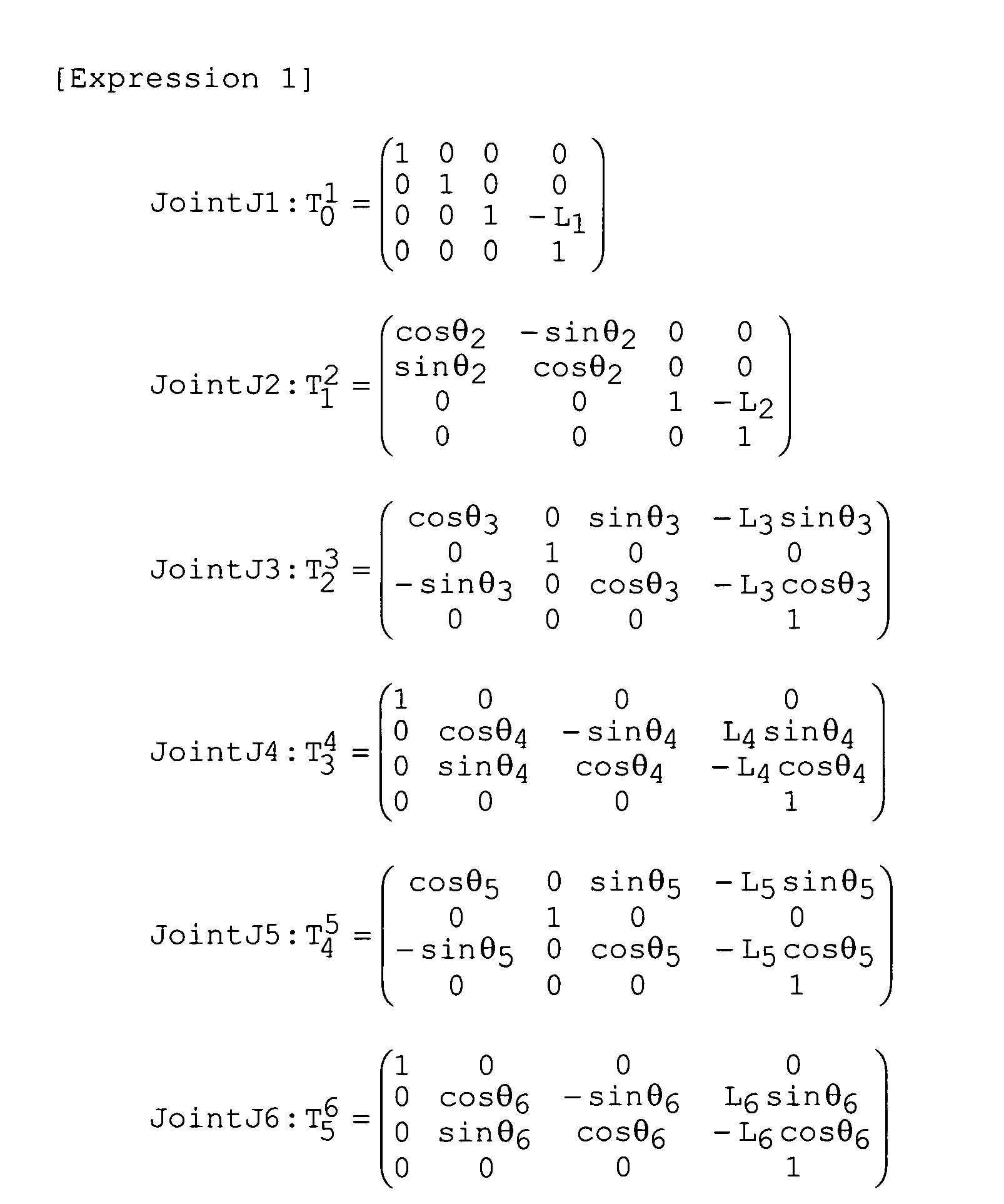
- Accordingly, a homogeneous conversion matrix is shown by
Expression 2.
- Since the coordinate system uses the
base end portion 141 as the reference, the position (x, y, z) and the attitude (θx, θy, θz) of the extreme end portion of themanipulation input unit 140 are determined byExpression 3.
- The configuration of the
surgical instrument 40 is different from that of themanipulation input unit 140. Accordingly, to operate thesurgical instrument 40 by operating themanipulation input unit 140, it is necessary to match the position and the attitude of thesurgical instrument 40 with those of themanipulation input unit 140. For this purpose, the rotation angles and the amounts of parallel (forward and rearward) movement of the respective joints of thesurgical instrument 40 must be determined. - As described above, the movement of the
surgical instrument 40 corresponds to that of themanipulation input unit 140. Accordingly, the position and the attitude of thesurgical instrument 40 are determined by those of themanipulation input unit 140. Assuming that the configuration of thesurgical instrument 40 is known, the rotation angles and the amounts of parallel movement of the respective configurations of thesurgical instrument 40 can be determined by inverse kinematics. Inverse kinematics is a method of estimating the specific values of the joints (angles and the like thereof) from the position/attitude information of the manipulator (surgical instrument 40) in a working space. The joint parameter Φ of therespective joints Expression 4.
- The position and the attitude of the manipulator are shown by
Expression 5.
- Thus, the relation thereof is shown by
Expression 6.
- Here, the target P of the position and the attitude of the manipulator is shown by
Expression 7.
- To place the manipulator in a Pp state, Φ must be determined to satisfy
Expression 8.
- However, since these expressions are non-linear, ordinarily, Jacobian matrix J(Φ) is determined by subjecting Ep to partial differentiation by the factor of Φ to determine Φ.

-
Expression 11 is determined fromExpression 10.

- Then, Φ that satisfies
Expression 11 is determined by a convergence calculation. - As a result, according to the embodiment, even when the configuration of the
manipulation input unit 140 is different from that of thesurgical instrument 40, the extreme end of thesurgical instrument 40 can be moved to an arbitrary position and an arbitrary attitude from the position and the attitude of themanipulation input unit 140, and an affected area can be cut out and exfoliated more easily than ever before. - The present invention can be also applied to a bending portion of an endoscope. The present invention can be applied to, for example, the bending mechanism of the bending portion in the insertion portion of the endoscope according to the embodiment described above. Further, the surgical instrument as a target of the present invention also includes a surgical catheter.
- According to the above explanation, there can be obtained multijointed medical equipment according to the following items or arbitrary combinations of the following items and the items according to the claims.
- 1. An endoscope surgical instrument including:
- an endoscope to observe an affected area in a body cavity;
- a surgical instrument to perform surgery on the affected area by passing through an insertion portion of the endoscope;
- at least one bending means disposed in an extreme end of the surgical instrument;
- manipulation means for moving the extreme end of the surgical instrument in a direction intended by an operator;
- control means for controlling movement of the extreme end of the surgical instrument in response to manipulation of the manipulation means; and
- means for operating the bending means of the surgical instrument in response to a control signal from the control means.
- 2. The endoscope surgical instrument according to
item 1, wherein the surgical instrument includes a soft insertion portion and a surgical portion for cutting out and exfoliating an affected area of a living body. - 3. The endoscope surgical instrument according to
item 1, wherein power for operating the bending means is assembled in the vicinity of the extreme end of the surgical instrument. - 4. The endoscope surgical instrument according to
item 1, in which power for operating the bending means is disposed in a portion other than the vicinity of the extreme end of the surgical instrument and which includes transmission means for transmitting the power to the bending means. - 5. The endoscope surgical instrument according to
item 1, including means for moving the extreme end of the surgical instrument forward and rearward.
Claims (10)
- A multijointed bending mechanism characterized by comprising:a first bending piece;a second bending piece connected to the first bending piece so as to be rotatable around a first rotation shaft;a third bending piece connected to the second bending piece so as to be rotatable around a second rotation shaft;at least two first wires connected to the first bending piece to rotate the first bending piece; andat least two second wires connected to the second bending piece to rotate the second bending piece,wherein the first wires are disposed inwards of the second wires with respect to a vertical direction of the first and second rotation shafts.
- The multijointed bending mechanism according to claim 1, characterized by further comprising positioning/disposing means disposed in the second bending piece for executing positioning so that the first wires are disposed inwards of the second wires.
- The multijointed bending mechanism according to claim 1, characterized by further comprising:a first elastic member connected to the second bending piece to guide the first wires; anda second elastic member connected to the third bending piece to guide the second wires.
- The multijointed bending mechanism according to claim 3, characterized by further comprising positioning/disposing means disposed in the second bending piece for executing positioning so that the first wires are disposed inwards of the second wires.
- A multijointed medical equipment comprising the multijointed bending mechanism according to claim 1.
- A multijointed bending mechanism characterized by comprising:a first bending piece;a second bending piece connected to the first bending piece so as to be rotatable around a first rotation shaft;a third bending piece connected to the second bending piece so as to be rotatable around a second rotation shaft;at least two first wires connected to the first bending piece to rotate the first bending piece; andat least two third wires connected to the third bending piece to rotate the third bending piece,wherein the first wires are disposed inwards of the third wires with respect to a vertical direction of the first and second rotation shafts.
- The multijointed bending mechanism according to claim 6, characterized by further comprising positioning/disposing means disposed in the third bending piece for executing positioning so that the first wires are disposed inwards of the third wires.
- The multijointed bending mechanism according to claim 6, characterized by further comprising:a first elastic member connected to the second bending piece to guide the first wires; anda third elastic member connected to a fourth bending piece rotatably connected to the third bending piece to guide the third wires.
- The multijointed bending mechanism according to claim 8, characterized by further comprising positioning/disposing means disposed in the third bending piece for executing positioning so that the first wires are disposed inwards of the third wires.
- A multijointed medical equipment comprising the multijointed bending mechanism according to claim 6.
Applications Claiming Priority (2)
| Application Number | Priority Date | Filing Date | Title |
|---|---|---|---|
| JP2007086482A JP5074069B2 (en) | 2007-03-29 | 2007-03-29 | Multi-joint bending mechanism and medical device with multi-joint bending mechanism |
| PCT/JP2007/074713 WO2008120426A1 (en) | 2007-03-29 | 2007-12-21 | Articulated bending mechanism and articulated medical device with articulated bending mechanism |
Publications (2)
| Publication Number | Publication Date |
|---|---|
| EP2130504A1 true EP2130504A1 (en) | 2009-12-09 |
| EP2130504A4 EP2130504A4 (en) | 2013-03-13 |
Family
ID=39808014
Family Applications (1)
| Application Number | Title | Priority Date | Filing Date |
|---|---|---|---|
| EP07851065A Pending EP2130504A4 (en) | 2007-03-29 | 2007-12-21 | ARTICULATED BENDING MECHANISM AND ARTICULATED MEDICAL DEVICE WITH ARTICULATED BEND MECHANISM |
Country Status (5)
| Country | Link |
|---|---|
| US (1) | US20100004508A1 (en) |
| EP (1) | EP2130504A4 (en) |
| JP (1) | JP5074069B2 (en) |
| CN (1) | CN101610724B (en) |
| WO (1) | WO2008120426A1 (en) |
Cited By (2)
| Publication number | Priority date | Publication date | Assignee | Title |
|---|---|---|---|---|
| WO2018142209A1 (en) * | 2017-02-02 | 2018-08-09 | Hoya Corporation | Wire guiding component and endoscope comprising at least one pulling wire |
| WO2020102436A1 (en) * | 2018-11-13 | 2020-05-22 | Interscope, Inc. | Systems and methods of endoscopic instruments with articulating end |
Families Citing this family (178)
| Publication number | Priority date | Publication date | Assignee | Title |
|---|---|---|---|---|
| US11229472B2 (en) | 2001-06-12 | 2022-01-25 | Cilag Gmbh International | Modular battery powered handheld surgical instrument with multiple magnetic position sensors |
| US8182501B2 (en) | 2004-02-27 | 2012-05-22 | Ethicon Endo-Surgery, Inc. | Ultrasonic surgical shears and method for sealing a blood vessel using same |
| EP3162309B1 (en) | 2004-10-08 | 2022-10-26 | Ethicon LLC | Ultrasonic surgical instrument |
| US20070191713A1 (en) | 2005-10-14 | 2007-08-16 | Eichmann Stephen E | Ultrasonic device for cutting and coagulating |
| US7621930B2 (en) | 2006-01-20 | 2009-11-24 | Ethicon Endo-Surgery, Inc. | Ultrasound medical instrument having a medical ultrasonic blade |
| US8226675B2 (en) | 2007-03-22 | 2012-07-24 | Ethicon Endo-Surgery, Inc. | Surgical instruments |
| US8911460B2 (en) | 2007-03-22 | 2014-12-16 | Ethicon Endo-Surgery, Inc. | Ultrasonic surgical instruments |
| US8142461B2 (en) | 2007-03-22 | 2012-03-27 | Ethicon Endo-Surgery, Inc. | Surgical instruments |
| US8057498B2 (en) | 2007-11-30 | 2011-11-15 | Ethicon Endo-Surgery, Inc. | Ultrasonic surgical instrument blades |
| US8523889B2 (en) | 2007-07-27 | 2013-09-03 | Ethicon Endo-Surgery, Inc. | Ultrasonic end effectors with increased active length |
| US8882791B2 (en) | 2007-07-27 | 2014-11-11 | Ethicon Endo-Surgery, Inc. | Ultrasonic surgical instruments |
| US8808319B2 (en) | 2007-07-27 | 2014-08-19 | Ethicon Endo-Surgery, Inc. | Surgical instruments |
| US9044261B2 (en) | 2007-07-31 | 2015-06-02 | Ethicon Endo-Surgery, Inc. | Temperature controlled ultrasonic surgical instruments |
| US8512365B2 (en) | 2007-07-31 | 2013-08-20 | Ethicon Endo-Surgery, Inc. | Surgical instruments |
| US8430898B2 (en) | 2007-07-31 | 2013-04-30 | Ethicon Endo-Surgery, Inc. | Ultrasonic surgical instruments |
| AU2008308606B2 (en) | 2007-10-05 | 2014-12-18 | Ethicon Endo-Surgery, Inc. | Ergonomic surgical instruments |
| US10010339B2 (en) | 2007-11-30 | 2018-07-03 | Ethicon Llc | Ultrasonic surgical blades |
| US8893015B2 (en) | 2008-07-03 | 2014-11-18 | Ebay Inc. | Multi-directional and variable speed navigation of collage multi-media |
| US8365092B2 (en) | 2008-07-03 | 2013-01-29 | Ebay Inc. | On-demand loading of media in a multi-media presentation |
| US10282391B2 (en) | 2008-07-03 | 2019-05-07 | Ebay Inc. | Position editing tool of collage multi-media |
| US9089360B2 (en) | 2008-08-06 | 2015-07-28 | Ethicon Endo-Surgery, Inc. | Devices and techniques for cutting and coagulating tissue |
| JP5484483B2 (en) * | 2008-12-10 | 2014-05-07 | アンブ・エ/エス | Endoscope bending part control mechanism |
| US9700339B2 (en) | 2009-05-20 | 2017-07-11 | Ethicon Endo-Surgery, Inc. | Coupling arrangements and methods for attaching tools to ultrasonic surgical instruments |
| US8334635B2 (en) | 2009-06-24 | 2012-12-18 | Ethicon Endo-Surgery, Inc. | Transducer arrangements for ultrasonic surgical instruments |
| US8663220B2 (en) | 2009-07-15 | 2014-03-04 | Ethicon Endo-Surgery, Inc. | Ultrasonic surgical instruments |
| USRE47996E1 (en) | 2009-10-09 | 2020-05-19 | Ethicon Llc | Surgical generator for ultrasonic and electrosurgical devices |
| US9039695B2 (en) | 2009-10-09 | 2015-05-26 | Ethicon Endo-Surgery, Inc. | Surgical generator for ultrasonic and electrosurgical devices |
| US11090104B2 (en) | 2009-10-09 | 2021-08-17 | Cilag Gmbh International | Surgical generator for ultrasonic and electrosurgical devices |
| US10441345B2 (en) | 2009-10-09 | 2019-10-15 | Ethicon Llc | Surgical generator for ultrasonic and electrosurgical devices |
| US9168054B2 (en) | 2009-10-09 | 2015-10-27 | Ethicon Endo-Surgery, Inc. | Surgical generator for ultrasonic and electrosurgical devices |
| WO2011092937A1 (en) | 2010-01-29 | 2011-08-04 | オリンパスメディカルシステムズ株式会社 | Inserting apparatus and endoscope |
| US8469981B2 (en) | 2010-02-11 | 2013-06-25 | Ethicon Endo-Surgery, Inc. | Rotatable cutting implement arrangements for ultrasonic surgical instruments |
| US8579928B2 (en) | 2010-02-11 | 2013-11-12 | Ethicon Endo-Surgery, Inc. | Outer sheath and blade arrangements for ultrasonic surgical instruments |
| US8961547B2 (en) | 2010-02-11 | 2015-02-24 | Ethicon Endo-Surgery, Inc. | Ultrasonic surgical instruments with moving cutting implement |
| US8486096B2 (en) | 2010-02-11 | 2013-07-16 | Ethicon Endo-Surgery, Inc. | Dual purpose surgical instrument for cutting and coagulating tissue |
| US8951272B2 (en) | 2010-02-11 | 2015-02-10 | Ethicon Endo-Surgery, Inc. | Seal arrangements for ultrasonically powered surgical instruments |
| EP2505117B1 (en) | 2010-03-08 | 2014-04-16 | Olympus Medical Systems Corp. | Medical device for multiple bends |
| JP5349388B2 (en) * | 2010-03-29 | 2013-11-20 | 富士フイルム株式会社 | Endoscope operation wire connecting device and endoscope |
| GB2480498A (en) | 2010-05-21 | 2011-11-23 | Ethicon Endo Surgery Inc | Medical device comprising RF circuitry |
| US8795327B2 (en) | 2010-07-22 | 2014-08-05 | Ethicon Endo-Surgery, Inc. | Electrosurgical instrument with separate closure and cutting members |
| US9192431B2 (en) | 2010-07-23 | 2015-11-24 | Ethicon Endo-Surgery, Inc. | Electrosurgical cutting and sealing instrument |
| US12402960B2 (en) | 2010-10-11 | 2025-09-02 | Ecole Polytechnique Federale De Lausanne (Epfl) | Mechanical manipulator for surgical instruments |
| WO2012049623A1 (en) | 2010-10-11 | 2012-04-19 | Ecole Polytechnique Federale De Lausanne (Epfl) | Mechanical manipulator for surgical instruments |
| JP5766940B2 (en) * | 2010-12-01 | 2015-08-19 | オリンパス株式会社 | Tubular insertion system |
| JP5506724B2 (en) * | 2011-03-18 | 2014-05-28 | 富士フイルム株式会社 | Endoscope device |
| US9259265B2 (en) | 2011-07-22 | 2016-02-16 | Ethicon Endo-Surgery, Llc | Surgical instruments for tensioning tissue |
| JP5715304B2 (en) | 2011-07-27 | 2015-05-07 | エコール ポリテクニーク フェデラル デ ローザンヌ (イーピーエフエル) | Mechanical remote control device for remote control |
| JP6165780B2 (en) | 2012-02-10 | 2017-07-19 | エシコン・エンド−サージェリィ・インコーポレイテッドEthicon Endo−Surgery,Inc. | Robot-controlled surgical instrument |
| US9241731B2 (en) | 2012-04-09 | 2016-01-26 | Ethicon Endo-Surgery, Inc. | Rotatable electrical connection for ultrasonic surgical instruments |
| US9724118B2 (en) | 2012-04-09 | 2017-08-08 | Ethicon Endo-Surgery, Llc | Techniques for cutting and coagulating tissue for ultrasonic surgical instruments |
| US9226766B2 (en) | 2012-04-09 | 2016-01-05 | Ethicon Endo-Surgery, Inc. | Serial communication protocol for medical device |
| US9237921B2 (en) | 2012-04-09 | 2016-01-19 | Ethicon Endo-Surgery, Inc. | Devices and techniques for cutting and coagulating tissue |
| US9439668B2 (en) | 2012-04-09 | 2016-09-13 | Ethicon Endo-Surgery, Llc | Switch arrangements for ultrasonic surgical instruments |
| WO2013190910A1 (en) * | 2012-06-22 | 2013-12-27 | オリンパスメディカルシステムズ株式会社 | Bending tube and medical instrument |
| US20140005705A1 (en) | 2012-06-29 | 2014-01-02 | Ethicon Endo-Surgery, Inc. | Surgical instruments with articulating shafts |
| US9198714B2 (en) | 2012-06-29 | 2015-12-01 | Ethicon Endo-Surgery, Inc. | Haptic feedback devices for surgical robot |
| US9351754B2 (en) | 2012-06-29 | 2016-05-31 | Ethicon Endo-Surgery, Llc | Ultrasonic surgical instruments with distally positioned jaw assemblies |
| US9408622B2 (en) | 2012-06-29 | 2016-08-09 | Ethicon Endo-Surgery, Llc | Surgical instruments with articulating shafts |
| US9820768B2 (en) * | 2012-06-29 | 2017-11-21 | Ethicon Llc | Ultrasonic surgical instruments with control mechanisms |
| US9226767B2 (en) | 2012-06-29 | 2016-01-05 | Ethicon Endo-Surgery, Inc. | Closed feedback control for electrosurgical device |
| US9283045B2 (en) | 2012-06-29 | 2016-03-15 | Ethicon Endo-Surgery, Llc | Surgical instruments with fluid management system |
| US9393037B2 (en) | 2012-06-29 | 2016-07-19 | Ethicon Endo-Surgery, Llc | Surgical instruments with articulating shafts |
| US9326788B2 (en) | 2012-06-29 | 2016-05-03 | Ethicon Endo-Surgery, Llc | Lockout mechanism for use with robotic electrosurgical device |
| US20140005702A1 (en) | 2012-06-29 | 2014-01-02 | Ethicon Endo-Surgery, Inc. | Ultrasonic surgical instruments with distally positioned transducers |
| WO2014052181A1 (en) | 2012-09-28 | 2014-04-03 | Ethicon Endo-Surgery, Inc. | Multi-function bi-polar forceps |
| US10201365B2 (en) | 2012-10-22 | 2019-02-12 | Ethicon Llc | Surgeon feedback sensing and display methods |
| US9095367B2 (en) | 2012-10-22 | 2015-08-04 | Ethicon Endo-Surgery, Inc. | Flexible harmonic waveguides/blades for surgical instruments |
| US20140135804A1 (en) | 2012-11-15 | 2014-05-15 | Ethicon Endo-Surgery, Inc. | Ultrasonic and electrosurgical devices |
| US20140275779A1 (en) * | 2013-03-12 | 2014-09-18 | Covidien Lp | Flexible Shaft with Multiple Flexible Portions |
| US10226273B2 (en) | 2013-03-14 | 2019-03-12 | Ethicon Llc | Mechanical fasteners for use with surgical energy devices |
| US9241728B2 (en) | 2013-03-15 | 2016-01-26 | Ethicon Endo-Surgery, Inc. | Surgical instrument with multiple clamping mechanisms |
| CN105073057B (en) * | 2013-03-18 | 2017-07-04 | 奥林巴斯株式会社 | manipulator |
| US9814514B2 (en) | 2013-09-13 | 2017-11-14 | Ethicon Llc | Electrosurgical (RF) medical instruments for cutting and coagulating tissue |
| US9265926B2 (en) | 2013-11-08 | 2016-02-23 | Ethicon Endo-Surgery, Llc | Electrosurgical devices |
| CN105636494B (en) * | 2013-11-29 | 2017-10-03 | 奥林巴斯株式会社 | Curvature section of endoscope |
| GB2521229A (en) | 2013-12-16 | 2015-06-17 | Ethicon Endo Surgery Inc | Medical device |
| GB2521228A (en) | 2013-12-16 | 2015-06-17 | Ethicon Endo Surgery Inc | Medical device |
| CN105828738B (en) | 2013-12-20 | 2018-10-09 | 奥林巴斯株式会社 | Guide member for flexible manipulator and flexible manipulator |
| US9795436B2 (en) | 2014-01-07 | 2017-10-24 | Ethicon Llc | Harvesting energy from a surgical generator |
| JP6220085B2 (en) | 2014-02-03 | 2017-10-25 | ディスタルモーション エスエーDistalmotion Sa | Mechanical remote control device with replaceable distal device |
| US9554854B2 (en) | 2014-03-18 | 2017-01-31 | Ethicon Endo-Surgery, Llc | Detecting short circuits in electrosurgical medical devices |
| US10092310B2 (en) | 2014-03-27 | 2018-10-09 | Ethicon Llc | Electrosurgical devices |
| US10463421B2 (en) | 2014-03-27 | 2019-11-05 | Ethicon Llc | Two stage trigger, clamp and cut bipolar vessel sealer |
| US9737355B2 (en) | 2014-03-31 | 2017-08-22 | Ethicon Llc | Controlling impedance rise in electrosurgical medical devices |
| US9913680B2 (en) | 2014-04-15 | 2018-03-13 | Ethicon Llc | Software algorithms for electrosurgical instruments |
| US10285724B2 (en) | 2014-07-31 | 2019-05-14 | Ethicon Llc | Actuation mechanisms and load adjustment assemblies for surgical instruments |
| EP3185808B1 (en) | 2014-08-27 | 2022-02-23 | DistalMotion SA | Surgical system for microsurgical techniques |
| US10639092B2 (en) | 2014-12-08 | 2020-05-05 | Ethicon Llc | Electrode configurations for surgical instruments |
| US10864049B2 (en) | 2014-12-19 | 2020-12-15 | Distalmotion Sa | Docking system for mechanical telemanipulator |
| WO2016097868A1 (en) | 2014-12-19 | 2016-06-23 | Distalmotion Sa | Reusable surgical instrument for minimally invasive procedures |
| EP3232974B1 (en) | 2014-12-19 | 2018-10-24 | DistalMotion SA | Articulated handle for mechanical telemanipulator |
| EP3232951B1 (en) | 2014-12-19 | 2023-10-25 | DistalMotion SA | Surgical instrument with articulated end-effector |
| US11039820B2 (en) | 2014-12-19 | 2021-06-22 | Distalmotion Sa | Sterile interface for articulated surgical instruments |
| US10245095B2 (en) | 2015-02-06 | 2019-04-02 | Ethicon Llc | Electrosurgical instrument with rotation and articulation mechanisms |
| WO2016129336A1 (en) * | 2015-02-13 | 2016-08-18 | オリンパス株式会社 | Manipulator |
| US10342602B2 (en) | 2015-03-17 | 2019-07-09 | Ethicon Llc | Managing tissue treatment |
| US10321950B2 (en) | 2015-03-17 | 2019-06-18 | Ethicon Llc | Managing tissue treatment |
| US10595929B2 (en) | 2015-03-24 | 2020-03-24 | Ethicon Llc | Surgical instruments with firing system overload protection mechanisms |
| EP3280343B1 (en) | 2015-04-09 | 2024-08-21 | DistalMotion SA | Mechanical teleoperated device for remote manipulation |
| EP3280337B1 (en) | 2015-04-09 | 2019-11-13 | DistalMotion SA | Articulated hand-held instrument |
| WO2016189646A1 (en) * | 2015-05-26 | 2016-12-01 | オリンパス株式会社 | Bending mechanism and flexible medical instrument |
| US10034684B2 (en) | 2015-06-15 | 2018-07-31 | Ethicon Llc | Apparatus and method for dissecting and coagulating tissue |
| US11020140B2 (en) | 2015-06-17 | 2021-06-01 | Cilag Gmbh International | Ultrasonic surgical blade for use with ultrasonic surgical instruments |
| US10034704B2 (en) | 2015-06-30 | 2018-07-31 | Ethicon Llc | Surgical instrument with user adaptable algorithms |
| US11129669B2 (en) | 2015-06-30 | 2021-09-28 | Cilag Gmbh International | Surgical system with user adaptable techniques based on tissue type |
| US10357303B2 (en) | 2015-06-30 | 2019-07-23 | Ethicon Llc | Translatable outer tube for sealing using shielded lap chole dissector |
| US11051873B2 (en) | 2015-06-30 | 2021-07-06 | Cilag Gmbh International | Surgical system with user adaptable techniques employing multiple energy modalities based on tissue parameters |
| US10765470B2 (en) | 2015-06-30 | 2020-09-08 | Ethicon Llc | Surgical system with user adaptable techniques employing simultaneous energy modalities based on tissue parameters |
| US10898256B2 (en) | 2015-06-30 | 2021-01-26 | Ethicon Llc | Surgical system with user adaptable techniques based on tissue impedance |
| US10154852B2 (en) | 2015-07-01 | 2018-12-18 | Ethicon Llc | Ultrasonic surgical blade with improved cutting and coagulation features |
| WO2017006377A1 (en) * | 2015-07-09 | 2017-01-12 | 川崎重工業株式会社 | Surgical robot |
| EP3340897B1 (en) | 2015-08-28 | 2024-10-09 | DistalMotion SA | Surgical instrument with increased actuation force |
| US10687884B2 (en) | 2015-09-30 | 2020-06-23 | Ethicon Llc | Circuits for supplying isolated direct current (DC) voltage to surgical instruments |
| US10595930B2 (en) | 2015-10-16 | 2020-03-24 | Ethicon Llc | Electrode wiping surgical device |
| US10179022B2 (en) | 2015-12-30 | 2019-01-15 | Ethicon Llc | Jaw position impedance limiter for electrosurgical instrument |
| US10575892B2 (en) | 2015-12-31 | 2020-03-03 | Ethicon Llc | Adapter for electrical surgical instruments |
| US11229471B2 (en) | 2016-01-15 | 2022-01-25 | Cilag Gmbh International | Modular battery powered handheld surgical instrument with selective application of energy based on tissue characterization |
| US11058448B2 (en) | 2016-01-15 | 2021-07-13 | Cilag Gmbh International | Modular battery powered handheld surgical instrument with multistage generator circuits |
| US10716615B2 (en) | 2016-01-15 | 2020-07-21 | Ethicon Llc | Modular battery powered handheld surgical instrument with curved end effectors having asymmetric engagement between jaw and blade |
| US12193698B2 (en) | 2016-01-15 | 2025-01-14 | Cilag Gmbh International | Method for self-diagnosing operation of a control switch in a surgical instrument system |
| US11129670B2 (en) | 2016-01-15 | 2021-09-28 | Cilag Gmbh International | Modular battery powered handheld surgical instrument with selective application of energy based on button displacement, intensity, or local tissue characterization |
| US10555769B2 (en) | 2016-02-22 | 2020-02-11 | Ethicon Llc | Flexible circuits for electrosurgical instrument |
| US10646269B2 (en) | 2016-04-29 | 2020-05-12 | Ethicon Llc | Non-linear jaw gap for electrosurgical instruments |
| US10702329B2 (en) | 2016-04-29 | 2020-07-07 | Ethicon Llc | Jaw structure with distal post for electrosurgical instruments |
| US10485607B2 (en) | 2016-04-29 | 2019-11-26 | Ethicon Llc | Jaw structure with distal closure for electrosurgical instruments |
| US10456193B2 (en) | 2016-05-03 | 2019-10-29 | Ethicon Llc | Medical device with a bilateral jaw configuration for nerve stimulation |
| CA3035415A1 (en) * | 2016-05-23 | 2017-11-30 | Imperial Innovations Limited | Surgical instrument, robotic arm and control system for a robotic arm |
| US10245064B2 (en) | 2016-07-12 | 2019-04-02 | Ethicon Llc | Ultrasonic surgical instrument with piezoelectric central lumen transducer |
| US10893883B2 (en) | 2016-07-13 | 2021-01-19 | Ethicon Llc | Ultrasonic assembly for use with ultrasonic surgical instruments |
| US10842522B2 (en) | 2016-07-15 | 2020-11-24 | Ethicon Llc | Ultrasonic surgical instruments having offset blades |
| US10376305B2 (en) | 2016-08-05 | 2019-08-13 | Ethicon Llc | Methods and systems for advanced harmonic energy |
| US10285723B2 (en) | 2016-08-09 | 2019-05-14 | Ethicon Llc | Ultrasonic surgical blade with improved heel portion |
| JP6349041B1 (en) * | 2016-08-10 | 2018-06-27 | オリンパス株式会社 | Curved tube and endoscope |
| USD847990S1 (en) | 2016-08-16 | 2019-05-07 | Ethicon Llc | Surgical instrument |
| US10729886B2 (en) * | 2016-08-24 | 2020-08-04 | Intuitive Surgical Operations, Inc. | Axial support structure for a flexible elongate device |
| US10952759B2 (en) | 2016-08-25 | 2021-03-23 | Ethicon Llc | Tissue loading of a surgical instrument |
| US10736649B2 (en) | 2016-08-25 | 2020-08-11 | Ethicon Llc | Electrical and thermal connections for ultrasonic transducer |
| US10603064B2 (en) | 2016-11-28 | 2020-03-31 | Ethicon Llc | Ultrasonic transducer |
| US11266430B2 (en) | 2016-11-29 | 2022-03-08 | Cilag Gmbh International | End effector control and calibration |
| US11058503B2 (en) | 2017-05-11 | 2021-07-13 | Distalmotion Sa | Translational instrument interface for surgical robot and surgical robot systems comprising the same |
| US10820920B2 (en) | 2017-07-05 | 2020-11-03 | Ethicon Llc | Reusable ultrasonic medical devices and methods of their use |
| US12376927B2 (en) | 2018-02-07 | 2025-08-05 | Distalmotion Sa | Surgical robot systems comprising robotic telemanipulators and integrated laparoscopy |
| CA3089681A1 (en) | 2018-02-07 | 2019-08-15 | Distalmotion Sa | Surgical robot systems comprising robotic telemanipulators and integrated laparoscopy |
| CN110269687B (en) * | 2018-03-14 | 2020-12-22 | 深圳市精锋医疗科技有限公司 | Translatable Link Components, Manipulator Arms, Slave Manipulators and Surgical Robots |
| KR102256826B1 (en) * | 2018-08-31 | 2021-05-27 | 한양대학교 에리카산학협력단 | Flexible mechanism |
| CN109480748A (en) * | 2018-10-31 | 2019-03-19 | 苏州佩斯夫智能科技有限公司 | It is a kind of can free bend medical endoscope and its application method |
| CN110368092B (en) * | 2019-08-15 | 2024-02-09 | 上海微创医疗机器人(集团)股份有限公司 | Surgical robots and surgical instruments |
| US12064109B2 (en) | 2019-12-30 | 2024-08-20 | Cilag Gmbh International | Surgical instrument comprising a feedback control circuit |
| US11779329B2 (en) | 2019-12-30 | 2023-10-10 | Cilag Gmbh International | Surgical instrument comprising a flex circuit including a sensor system |
| US11660089B2 (en) | 2019-12-30 | 2023-05-30 | Cilag Gmbh International | Surgical instrument comprising a sensing system |
| US11452525B2 (en) | 2019-12-30 | 2022-09-27 | Cilag Gmbh International | Surgical instrument comprising an adjustment system |
| US20210196361A1 (en) | 2019-12-30 | 2021-07-01 | Ethicon Llc | Electrosurgical instrument with monopolar and bipolar energy capabilities |
| US12343063B2 (en) | 2019-12-30 | 2025-07-01 | Cilag Gmbh International | Multi-layer clamp arm pad for enhanced versatility and performance of a surgical device |
| US12114912B2 (en) | 2019-12-30 | 2024-10-15 | Cilag Gmbh International | Non-biased deflectable electrode to minimize contact between ultrasonic blade and electrode |
| US12053224B2 (en) | 2019-12-30 | 2024-08-06 | Cilag Gmbh International | Variation in electrode parameters and deflectable electrode to modify energy density and tissue interaction |
| US12076006B2 (en) | 2019-12-30 | 2024-09-03 | Cilag Gmbh International | Surgical instrument comprising an orientation detection system |
| US11812957B2 (en) | 2019-12-30 | 2023-11-14 | Cilag Gmbh International | Surgical instrument comprising a signal interference resolution system |
| US12262937B2 (en) | 2019-12-30 | 2025-04-01 | Cilag Gmbh International | User interface for surgical instrument with combination energy modality end-effector |
| US11950797B2 (en) | 2019-12-30 | 2024-04-09 | Cilag Gmbh International | Deflectable electrode with higher distal bias relative to proximal bias |
| US12023086B2 (en) | 2019-12-30 | 2024-07-02 | Cilag Gmbh International | Electrosurgical instrument for delivering blended energy modalities to tissue |
| US12336747B2 (en) | 2019-12-30 | 2025-06-24 | Cilag Gmbh International | Method of operating a combination ultrasonic / bipolar RF surgical device with a combination energy modality end-effector |
| US11779387B2 (en) | 2019-12-30 | 2023-10-10 | Cilag Gmbh International | Clamp arm jaw to minimize tissue sticking and improve tissue control |
| US11986201B2 (en) | 2019-12-30 | 2024-05-21 | Cilag Gmbh International | Method for operating a surgical instrument |
| US12082808B2 (en) | 2019-12-30 | 2024-09-10 | Cilag Gmbh International | Surgical instrument comprising a control system responsive to software configurations |
| US11707318B2 (en) | 2019-12-30 | 2023-07-25 | Cilag Gmbh International | Surgical instrument with jaw alignment features |
| US11911063B2 (en) | 2019-12-30 | 2024-02-27 | Cilag Gmbh International | Techniques for detecting ultrasonic blade to electrode contact and reducing power to ultrasonic blade |
| US11696776B2 (en) | 2019-12-30 | 2023-07-11 | Cilag Gmbh International | Articulatable surgical instrument |
| US11786291B2 (en) | 2019-12-30 | 2023-10-17 | Cilag Gmbh International | Deflectable support of RF energy electrode with respect to opposing ultrasonic blade |
| US11986234B2 (en) | 2019-12-30 | 2024-05-21 | Cilag Gmbh International | Surgical system communication pathways |
| US12349961B2 (en) | 2019-12-30 | 2025-07-08 | Cilag Gmbh International | Electrosurgical instrument with electrodes operable in bipolar and monopolar modes |
| US11944366B2 (en) | 2019-12-30 | 2024-04-02 | Cilag Gmbh International | Asymmetric segmented ultrasonic support pad for cooperative engagement with a movable RF electrode |
| US11723716B2 (en) | 2019-12-30 | 2023-08-15 | Cilag Gmbh International | Electrosurgical instrument with variable control mechanisms |
| US11937863B2 (en) | 2019-12-30 | 2024-03-26 | Cilag Gmbh International | Deflectable electrode with variable compression bias along the length of the deflectable electrode |
| CN111388083B (en) * | 2020-03-26 | 2023-04-11 | 平阴县中医医院 | Multi-angle operation electric coagulation forceps for stomatology department |
| JP7657094B2 (en) | 2021-04-30 | 2025-04-04 | 日本発條株式会社 | Bent Structure |
| CN113081243B (en) * | 2021-05-12 | 2024-07-19 | 中国人民解放军总医院第一医学中心 | A visible and controllable curved nipple incision knife |
| EP4401666A1 (en) | 2021-09-13 | 2024-07-24 | DistalMotion SA | Instruments for surgical robotic system and interfaces for the same |
| US11844585B1 (en) | 2023-02-10 | 2023-12-19 | Distalmotion Sa | Surgical robotics systems and devices having a sterile restart, and methods thereof |
Family Cites Families (11)
| Publication number | Priority date | Publication date | Assignee | Title |
|---|---|---|---|---|
| US3557780A (en) * | 1967-04-20 | 1971-01-26 | Olympus Optical Co | Mechanism for controlling flexure of endoscope |
| JP2987452B2 (en) * | 1990-05-17 | 1999-12-06 | オリンパス光学工業株式会社 | Endoscope |
| JPH0482688A (en) * | 1990-07-23 | 1992-03-16 | Res Dev Corp Of Japan | Wire driving type multi-joint arm |
| JPH0817768B2 (en) * | 1990-11-06 | 1996-02-28 | 富士写真光機株式会社 | Endoscope |
| JPH06105797A (en) * | 1992-09-29 | 1994-04-19 | Olympus Optical Co Ltd | Curving device |
| JPH06114000A (en) * | 1992-09-30 | 1994-04-26 | Olympus Optical Co Ltd | Medical manipulator |
| JP3279410B2 (en) * | 1993-10-22 | 2002-04-30 | オリンパス光学工業株式会社 | Endoscope |
| US20030135204A1 (en) * | 2001-02-15 | 2003-07-17 | Endo Via Medical, Inc. | Robotically controlled medical instrument with a flexible section |
| JP2003126024A (en) * | 2001-10-23 | 2003-05-07 | Olympus Optical Co Ltd | Endoscope |
| US20040199052A1 (en) * | 2003-04-01 | 2004-10-07 | Scimed Life Systems, Inc. | Endoscopic imaging system |
| JP2007054400A (en) * | 2005-08-25 | 2007-03-08 | Olympus Medical Systems Corp | Endoscope |
-
2007
- 2007-03-29 JP JP2007086482A patent/JP5074069B2/en not_active Expired - Fee Related
- 2007-12-21 EP EP07851065A patent/EP2130504A4/en active Pending
- 2007-12-21 CN CN2007800514446A patent/CN101610724B/en active Active
- 2007-12-21 WO PCT/JP2007/074713 patent/WO2008120426A1/en not_active Ceased
-
2009
- 2009-09-10 US US12/556,873 patent/US20100004508A1/en not_active Abandoned
Cited By (2)
| Publication number | Priority date | Publication date | Assignee | Title |
|---|---|---|---|---|
| WO2018142209A1 (en) * | 2017-02-02 | 2018-08-09 | Hoya Corporation | Wire guiding component and endoscope comprising at least one pulling wire |
| WO2020102436A1 (en) * | 2018-11-13 | 2020-05-22 | Interscope, Inc. | Systems and methods of endoscopic instruments with articulating end |
Also Published As
| Publication number | Publication date |
|---|---|
| US20100004508A1 (en) | 2010-01-07 |
| CN101610724B (en) | 2011-11-09 |
| CN101610724A (en) | 2009-12-23 |
| WO2008120426A1 (en) | 2008-10-09 |
| JP5074069B2 (en) | 2012-11-14 |
| EP2130504A4 (en) | 2013-03-13 |
| JP2008237810A (en) | 2008-10-09 |
Similar Documents
| Publication | Publication Date | Title |
|---|---|---|
| EP2130504A1 (en) | Articulated bending mechanism and articulated medical device with articulated bending mechanism | |
| EP2130478B1 (en) | Articulated bending mechanism and articulated medical device with articulated bending mechanism | |
| EP2127591A1 (en) | Articulated bending mechanism and articulated medicaldevice with articulated bending mechanism | |
| US8282543B2 (en) | Surgical instrument and endoscope surgical system having surgical instrument | |
| US11026759B2 (en) | Splayed cable guide for a medical instrument | |
| KR102332869B1 (en) | surgical device | |
| EP2092874B1 (en) | Manipulator operation system | |
| US8597280B2 (en) | Surgical instrument actuator | |
| JP2020192376A (en) | Surgical equipment | |
| US20180214220A1 (en) | Surgical robot | |
| US20230172680A1 (en) | Medical instrument having single input for driving multiple cables | |
| JP6404537B1 (en) | Medical treatment tool | |
| EP4706551A2 (en) | Low-friction, small profile medical tools having easy-to-assemble components | |
| KR20240158914A (en) | Medical Device Wrist | |
| WO2024058098A1 (en) | Movable long structure and method for manipulating same, medical system, tool, robot and method for operating same, manipulator, flexible endoscope, and steering catheter | |
| US20250120780A1 (en) | Mechanical advantage devices for medical devices | |
| Ying et al. | Flexible steerable manipulator utilizing complementary configuration of multiple routing grooves and ball joints for stable omnidirectional bending | |
| WO2025085388A1 (en) | Rotary to linear force articulation members for surgical instruments |
Legal Events
| Date | Code | Title | Description |
|---|---|---|---|
| PUAI | Public reference made under article 153(3) epc to a published international application that has entered the european phase |
Free format text: ORIGINAL CODE: 0009012 |
|
| 17P | Request for examination filed |
Effective date: 20090909 |
|
| AK | Designated contracting states |
Kind code of ref document: A1 Designated state(s): AT BE BG CH CY CZ DE DK EE ES FI FR GB GR HU IE IS IT LI LT LU LV MC MT NL PL PT RO SE SI SK TR |
|
| DAX | Request for extension of the european patent (deleted) | ||
| A4 | Supplementary search report drawn up and despatched |
Effective date: 20130213 |
|
| RIC1 | Information provided on ipc code assigned before grant |
Ipc: A61B 18/12 20060101ALI20130207BHEP Ipc: A61B 1/00 20060101ALI20130207BHEP Ipc: A61B 17/28 20060101AFI20130207BHEP |
|
| 17Q | First examination report despatched |
Effective date: 20140416 |
|
| RAP1 | Party data changed (applicant data changed or rights of an application transferred) |
Owner name: OLYMPUS CORPORATION |
|
| STAA | Information on the status of an ep patent application or granted ep patent |
Free format text: STATUS: EXAMINATION IS IN PROGRESS |
|
| RAP1 | Party data changed (applicant data changed or rights of an application transferred) |
Owner name: OLYMPUS CORPORATION |
|
| RAP1 | Party data changed (applicant data changed or rights of an application transferred) |
Owner name: OLYMPUS CORPORATION |