EP2129601B1 - Verfahren und kommissionierautomat zum befüllen eines auftragsbehälters - Google Patents
Verfahren und kommissionierautomat zum befüllen eines auftragsbehälters Download PDFInfo
- Publication number
- EP2129601B1 EP2129601B1 EP08716405A EP08716405A EP2129601B1 EP 2129601 B1 EP2129601 B1 EP 2129601B1 EP 08716405 A EP08716405 A EP 08716405A EP 08716405 A EP08716405 A EP 08716405A EP 2129601 B1 EP2129601 B1 EP 2129601B1
- Authority
- EP
- European Patent Office
- Prior art keywords
- accordance
- product
- belt
- products
- circulating
- Prior art date
- Legal status (The legal status is an assumption and is not a legal conclusion. Google has not performed a legal analysis and makes no representation as to the accuracy of the status listed.)
- Not-in-force
Links
- 238000000034 method Methods 0.000 title claims abstract description 18
- 238000003860 storage Methods 0.000 claims abstract description 28
- 230000008021 deposition Effects 0.000 claims 1
- XAGFODPZIPBFFR-UHFFFAOYSA-N aluminium Chemical compound [Al] XAGFODPZIPBFFR-UHFFFAOYSA-N 0.000 description 2
- 229910052782 aluminium Inorganic materials 0.000 description 2
- 235000017060 Arachis glabrata Nutrition 0.000 description 1
- 241001553178 Arachis glabrata Species 0.000 description 1
- 235000010777 Arachis hypogaea Nutrition 0.000 description 1
- 235000018262 Arachis monticola Nutrition 0.000 description 1
- 230000014759 maintenance of location Effects 0.000 description 1
- 235000020232 peanut Nutrition 0.000 description 1
- 238000011144 upstream manufacturing Methods 0.000 description 1
Images





Classifications
-
- B—PERFORMING OPERATIONS; TRANSPORTING
- B65—CONVEYING; PACKING; STORING; HANDLING THIN OR FILAMENTARY MATERIAL
- B65G—TRANSPORT OR STORAGE DEVICES, e.g. CONVEYORS FOR LOADING OR TIPPING, SHOP CONVEYOR SYSTEMS OR PNEUMATIC TUBE CONVEYORS
- B65G1/00—Storing articles, individually or in orderly arrangement, in warehouses or magazines
- B65G1/02—Storage devices
- B65G1/04—Storage devices mechanical
- B65G1/137—Storage devices mechanical with arrangements or automatic control means for selecting which articles are to be removed
- B65G1/1373—Storage devices mechanical with arrangements or automatic control means for selecting which articles are to be removed for fulfilling orders in warehouses
- B65G1/1376—Storage devices mechanical with arrangements or automatic control means for selecting which articles are to be removed for fulfilling orders in warehouses the orders being assembled on a commissioning conveyor
-
- B—PERFORMING OPERATIONS; TRANSPORTING
- B65—CONVEYING; PACKING; STORING; HANDLING THIN OR FILAMENTARY MATERIAL
- B65G—TRANSPORT OR STORAGE DEVICES, e.g. CONVEYORS FOR LOADING OR TIPPING, SHOP CONVEYOR SYSTEMS OR PNEUMATIC TUBE CONVEYORS
- B65G15/00—Conveyors having endless load-conveying surfaces, i.e. belts and like continuous members, to which tractive effort is transmitted by means other than endless driving elements of similar configuration
- B65G15/30—Belts or like endless load-carriers
- B65G15/32—Belts or like endless load-carriers made of rubber or plastics
- B65G15/42—Belts or like endless load-carriers made of rubber or plastics having ribs, ridges, or other surface projections
- B65G15/44—Belts or like endless load-carriers made of rubber or plastics having ribs, ridges, or other surface projections for impelling the loads
-
- B—PERFORMING OPERATIONS; TRANSPORTING
- B65—CONVEYING; PACKING; STORING; HANDLING THIN OR FILAMENTARY MATERIAL
- B65G—TRANSPORT OR STORAGE DEVICES, e.g. CONVEYORS FOR LOADING OR TIPPING, SHOP CONVEYOR SYSTEMS OR PNEUMATIC TUBE CONVEYORS
- B65G2201/00—Indexing codes relating to handling devices, e.g. conveyors, characterised by the type of product or load being conveyed or handled
- B65G2201/02—Articles
Definitions
- the invention relates to a method and a picking machine for filling a job container by means of ejector and conveyor belt according to the preamble of claim 1 or 9. Such a method is already out US 4 569 435 A known.
- a picking machine with ejectors for picking products onto a conveyor belt wherein the products picked on the conveyor belt are transported to a job container and delivered to this order container.
- Each ejector upstream and superior to a product memory which extends as a vertical shaft slightly inclined to the vertical of the picking machine. In the vertical shaft, sorted products are stacked in direct contact.
- the horizontal ejector located at the bottom of the product stack pushes the bottom of the stack towards the conveyor if needed. If the bottom product is ejected, the product stack shifts down by one product height due to its own weight. In this way, products can be ejected occasionally or picked.
- a disadvantage in addition to the limited product stack height or product storage capacity in particular is that only stackable products can usually be stored and picked in cuboid form. Unshaped products are eliminated. However, if misshapen, ie non-stackable products are to be picked, these products must be picked by an operator by hand from a storage container and either placed on the conveyor belt or introduced directly into the order container.
- the object of the invention is to provide a method and a picking machine for filling a job container of the type mentioned, in which also shapeless, d. H. Non-stackable products can be picked reliably, quickly and effectively.
- Essence of the invention in a method mentioned and picking for filling a job container by ejector and conveyor belt is that products to be picked stored in the circulating belt ejector itself as a horizontal product series at standstill of the circulating belt and by pressing the circulating belt on the conveyor or directly into the order container are delivered.
- the ejector is thus designed according to the invention itself as a product (-Haupt) memory of the picking - not as an auxiliary storage, for example, in a connection to a flow shelf.
- the ejector according to the invention does not have to be exactly horizontal. It is understood that he can also be inclined and therefore arranged obliquely with respect to the horizontal.
- a single product store stores primarily identical identical products.
- each product to be picked can be singularly entered in each case on a product storage space of the revolving belt, preferably in a product compartment of the revolving belt and stored, and it can be submitted isolated on the product memory locations, in particular in the product compartments, products.
- this may also be a circulating link chain, a studded or studded belt or the like in the context of the present invention.
- the invention allows in particular shapeless, irregularly configured products to be automatically stored and picked in a picking machine - products that can not be automated with the ejectors known from the aforementioned prior art. It can be automated products in almost any size or shapes, such as teddy bears, peanut bags, coffee packs, gauze bandages and the like. There are no cuboid dimensions necessary. Stackability of the products is not a requirement.
- one or more products are thrown onto the conveyor belt positioned at the head of the circulating belt.
- the conveyor belt is preferably the central belt of the picking machine itself.
- the ejector can be controlled with conventional central belt technology. Products are thrown at exactly the right time onto an area of the central belt that is assigned to an order.
- the products stored in product compartments can preferably be partly slipped onto the conveyor belt.
- conventional product columns with stackable products can also be stored in vertical shafts and fed to the conveyor belt by means of lower conventional ejectors.
- the ejector according to the invention can be used for level management and / or automatic inventory.
- the product storage locations in particular the product compartments, can also be defined as virtual storage locations for products.
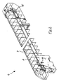
- a picking machine 1 comprises ejectors in the form of horizontal product stores for picking products 3 onto a conveyor belt 2, wherein the products 3 picked on the conveyor belt are transported to an order container 10 and delivered to this order container.
- the order container contains the products of a single picking order.
- the picking machine 1 is a so-called central belt machine and as such has a lower horizontal conveyor belt 2 in the form of a so-called central belt, which runs longitudinally to the A-frame 8 of the picking machine.
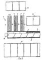
- FIG. 5 Located to the left of the A-frame 8 longitudinal side of the order picking machine 1 is filled with stackable products from the overstock 13 as in the above-mentioned prior art. The products are then stored in a stack in vertical order picking chutes, which are in accordance with FIG. 5 , left oblique plane of the A-frame 8 lie.
- the longitudinal side of the picking machine 1 located to the right of the A-frame 8 is filled according to the invention with bulky, ie non-stackable, products 3 from the overflow shelves 11 and 12, as will be described below.
- the horizontal product storage according to the invention is a drivable and controllable for a single ejection of a product 3 on the conveyor belt 2 circulating belt 4 with product storage locations, in particular with product compartments 5, which extend in close line along the circumference.
- the product compartments 5 have vertical knobs, bars or transverse walls 6 according to the Figures 2 and 7 on, which preferably extend over the entire width of the circulating belt 4 perpendicular to the circulating belt.
- the product storage locations in particular the product compartments 5, may be in a tight row arranged along the circumferential length of the circulating belt 4 and be defined as virtual storage locations for products 3.
- the distance between adjacent knobs, bars or transverse walls 6 is adjustable.
- the circulating belt 4 according to FIG. 3 has a cross-sectionally double-T-shaped profile 4 ', which is displaceably guided in a self-supporting aluminum profile 14 and by a motor M on the head side of the circulating belt 4 according to FIG. 4 is driven. Side of the profile 4 'brackets 21 for sensors and (not illustrated) side guides and covers are attached.
- the aluminum profile 4 ' carries the weight of the products 3 on a module holder or on the A-frame 8. At the rear longitudinal end E2 of the circulating belt 4, the weight of the products 3 is supported by vertical supports 9 on the ground.
- each circulating belt 4 comprises four sensors.
- a refill sensor 15 according to FIG. 2 who is in greater detail in FIG. 7 you can see.
- the circulating belt 4 may be composed of chain links.
- Individual chain links can be designed as transverse walls, which can be installed at desired longitudinal distances to form an individual product compartment 5.
- the upper run of the circulating belt 4 has stationary vertical longitudinal side walls 7 according to FIG. 2 ,
- the distance between the two longitudinal side walls 7 may optionally be formed adjustable.
- the one longitudinal end E1 of the circulating belt 4 lies above or in the region of the conveyor belt 2, and each product storage space, in particular each product compartment 5, is provided for a single product 3.
- the circulating belt 4 extends perpendicular or obliquely to the conveyor belt second
- the product storage locations, in particular product compartments 5, of the upper strand of the circulating belt 4 can be equipped with products 3.
- an operating room B may be provided for lateral filling of the product storage by an operator.
- FIG. 1 only a single horizontal plane is shown on horizontal circulating belts in a variant embodiment, in a further embodiment, several horizontal circulation belts 4 arranged one above the other, as shown in FIG. 4 is shown schematically.
- Higher lying circulating belts 4 are optionally inclined and located lower on the side facing away from the conveyor belt 2.
- the aforementioned substantially horizontal circulating belts 4 are in the arrangement according to FIG. 5 shown on the top left.
- An operator fills these circulating belts 4, if necessary, from the rear longitudinal end E2 of the circulating belts, from the longitudinal side L or from the control room B.
- the non-stackable products 4 required for filling are picked up by the operator from the overstocking shelves 11 which are within reach. The filling is confirmed the operator by pressing a button.
- Each product 3 to be picked is individually input and stored on a product storage space of the circulating belt 4, preferably in a product compartment 5 of the circulating belt, and the products stored on the product storage locations, in particular in the product compartments, are delivered in isolated form.
- a button 20 for filling request is attached, with which the horizontal product line of the minimum level F in the direction of arrow FIG. 6a to the rearmost position of the circulating belt according to FIG. 6b is driven.
- the refill sensor 15 detects the presence of the product line and clocks again to a product tray according to the arrow direction of Figure 6b to the left.
- the operator fills in accordance with FIG. 6c now a product 3 in the rearmost product compartment, and the refill sensor 15 clocks the circulating belt around a product compartment in the direction of arrow according to FIG.
- the circulating belt 4 is moved backwards by a predetermined distance automatically or by manual operation, and the minimum filling level F is visually and / or acoustically displayed on products 3 stored on the circulating belt 4.
- the ejector can be used for level management and / or automatic inventory.
- the ejector manages the filling level by counting the ejections made by the ejection sensor 17 since the last filling and placing them in relation to the total channel length or product storage length.
- control computer of the order-picking machine can request the channel or the product memory for inventory.
- the channel carries its product range R only once backwards and again forward, and counts the free product compartments.
- the required replenishment of products can also be recorded.
- the guided filling of the channels at the rear end automatically detects the refilled quantity and can be forwarded to a higher-level inventory management system.
Landscapes
- Engineering & Computer Science (AREA)
- Mechanical Engineering (AREA)
- Warehouses Or Storage Devices (AREA)
- Container Filling Or Packaging Operations (AREA)
- Supplying Of Containers To The Packaging Station (AREA)
- Filling Or Emptying Of Bunkers, Hoppers, And Tanks (AREA)
Description
- Die Erfindung betrifft ein Verfahren und einen Kommissionierautomaten zum Befüllen eines Auftragsbehälters mittels Auswerfer und Förderband gemäß dem Oberbegriff des Anspruchs 1 bzw. 9. Ein derartiges Verfahren ist bereits aus
US 4 569 435 A bekannt. - Aus
EP 0 213 360 A1 ist ein Kommissionierautomat mit Auswerfern zum Kommissionieren von Produkten auf ein Förderband bekannt, wobei die auf das Förderband kommissionierten Produkte zu einem Auftragsbehälter transportiert und in diesen Auftragsbehälter abgeben werden. Jedem Auswerfer vor- und übergeordnet ist ein Produktspeicher, der sich als Vertikalschacht leicht geneigt zur Vertikalen des Kommissionierautomaten erstreckt. Im Vertikalschacht sind sortenrein Produkte in unmittelbarer Berührung aufeinandergestapelt. Der an tiefster Stelle des Produktstapels gelegene horizontale Auswerfer schiebt bei Bedarf das unterste Produkt des Stapels in Richtung Förderband aus. Ist das unterste Produkt ausgeworfen, verlagert sich der Produktstapel aufgrund seines Eigengewichts um eine Produkthöhe nach unten. Auf diese Weise können Produkte vereinzelt ausgeworfen bzw. kommissioniert werden. Von Nachteil neben der begrenzten Produktstapelhöhe bzw. Produktspeicherkapazität insbesondere ist, dass nur stapelbare Produkte zumeist in Quaderform gespeichert und kommissioniert werden können. Unförmige Produkte scheiden aus. Sollen gleichwohl unförmige, d.h. nicht stapelbare Produkte mitkommissioniert werden, müssen diese Produkte von einer Bedienungsperson von Hand aus einem Vorratsbehälter kommissioniert und entweder auf das Förderband gelegt oder direkt in den Auftragsbehälter eingebracht werden. - Aufgabe der Erfindung ist die Schaffung eines Verfahrens und eines Kommissionierautomaten zum Befüllen eines Auftragsbehälters der eingangs genannten Art, bei dem auch unförmige, d. h. nicht-stapelbare Produkte zuverlässig, schnell und effektiv kommissioniert werden können.
- Gelöst wird die der Erfindung zugrundeliegende Aufgabe durch ein Verfahren der im Anspruch 1 angegebenen Art, vorteilhaft weitergebildet durch die Merkmale der Ansprüche 2 bis 8.
- Vorteilhafte Kommissionieraut aten kennzeichnen sich durch die Merkmale der Ansprüche 9 bis 25.
- Wesen der Erfindung bei einem eingangs genannten Verfahren und Kommissionierautomaten zum Befüllen eines Auftragsbehälters mittels Auswerfer und Förderband ist, dass zu kommissionierende Produkte in den als Umlaufband ausgebildeten Auswerfer selbst als horizontale Produktreihe bei Stillstand des Umlaufbandes gespeichert und durch Betätigen des Umlaufbandes auf das Förderband oder direkt in den Auftragsbehälter abgegeben werden. Der Auswerfer ist also erfindungsgemäß selbst als Produkt(-Haupt)-Speicher des Kommissionierautomaten ausgebildet - nicht etwa als Hilfsspeicher beispielweise in einem Anschluss an ein Durchlaufregal. Der erfindungsgemäße Auswerfer muss nicht exakt horizontal verlaufen. Es versteht sich, dass er bezüglich der Horizontalen auch geneigt und mithin schräg angeordnet sein kann. In einem einzigen Produktspeicher sind primär sortenreine identische Produkte gespeichert.
- Es kann vorzugsweise jedes zu kommissionierende Produkt vereinzelt jeweils auf einem Produktspeicherplatz des Umlaufbandes, vorzugsweise in ein Produktfach des Umlaufbandes, eingegeben und gespeichert werden, und es können die auf den Produktspeicherplätzen, insbesondere in den Produktfächern, gespeicherten Produkte vereinzelt abgegeben werden.
- Wenn von einem Umlaufband die Rede ist, so kann dies im Rahmen der vorliegenden Erfindung auch eine Umlauf-Gliederkette, ein Stollen- oder Noppenband oder dergleichen sein.
- Durch die Erfindung können insbesondere unförmige, unregelmäßig konfigurierte Produkte automatengerecht gespeichert und in einem Kommissionierautomaten kommissioniert werden - Produkte, die mit den aus dem eingangs genannten Stand der Technik bekannten Auswerfern nicht automatisierbar sind. Es können Produkte in nahezu beliebigen Abmessungen bzw. Formen automatisiert werden, wie Teddybären, Erdnussbeutel, Kaffeepackungen, Mullbinden und dergleichen. Es sind keine quaderförmigen Abmessungen notwendig. Stapelbarkeit der Produkte ist nicht Bedingung.
- Bei Bedarf werden ein oder mehrere Produkte auf das am Kopfende des Umlaufbandes positionierte Förderband geworfen. Das Förderband ist bevorzugt das Zentralband des Kommissionierautomaten selbst. Der Auswerfer kann mit herkömmlicher Zentralbandtechnologie angesteuert werden. Produkte werden dabei exakt zum richtigen Zeitpunkt auf einen Bereich des Zentralbands geworfen, welcher einem Auftrag zugeordnet ist.
- Von Vorteil ferner ist, dass der manuelle Vorgang des Befüllens des Produktspeichers zeitlich vom Kommissioniervorgang entkoppelt ist ("Vorrat im Kanal"). Eine durch Füllstandsanzeige am Kanalende geführte Nachfüllung ist möglich. Die Erfindung erlaubt beliebige konstruktive Kombinationen mit bestehenden Zentralbandautomaten (Modulbauweise). Im wesentlichen horizontale Produktspeicher sind nicht nur nebeneinander mit oder ohne Abstand voneinander, sondern auch in zwei oder mehreren Ebenen übereinander möglich. Verschiedene Kanalbreiten und verschiedene Noppen- oder Querwand-Abstände je nach Produktdimensionen können eingerichtet werden.
- Die in Produktfächern gespeicherten Produkte können aufgrund ihres Eigengewichts vorzugsweise zum Teil rutschend auf das Förderband abgegeben werden. Im Kommissionierautomaten können auch konventionelle Produktsäulen mit stapelbaren Produkten in vertikalen Schächten gespeichert und mit Hilfe von unteren konventionellen Ausschiebern dem Förderband zugeführt werden.
- Der erfindungsgemäße Auswerfer kann zur Füllstandsverwaltung und/oder zur automatischen Inventur verwendet werden.
- Die Produktspeicherplätze, insbesondere die Produktfächer, können auch als virtuelle Ablagestellen für Produkte definiert sein.
- Die Erfindung wird nachfolgend anhand von Ausführungsbeispielen unter Bezugnahme auf die beigefügten Zeichnungen näher beschrieben; es zeigen:
- Figur 1
- schematisch perspektivisch einen erfindungsgemäßen Kommissionierautomaten mit zentralem Förderband und Auswerfern in Form von horizontalen, in einer Ebene gelegenen Produktspeichern,
- Figur 2
- einen Produktspeicher der
Figur 1 in einer perspekti- vischen Ansicht, - Figur 3
- einen schematischen Querschnitt durch einen Produkt- speicher unter Weglassung von Längsseitenwänden,
- Figur 4
- eine schematische Seitenansicht des Kommissionierau- tomaten nach
Figur 1 mit einer weiteren Ebene an ho- rizontalen Produktspeichern, - Figur 5
- eine schematische Draufsicht auf einen erfindungsge- mäßen Kommissionierautomaten zusammen mit benachbar- ten Übervorratsregalen,
- Figuren 6a bis 6d
- einen Produktspeicher nach
Figur 4 in vier Stellungen einer Befüllung von Produkten von hinten gemäß Zeichnung rechts, und - Figur 7
- eine Einzelheit der
Figur 2 , rechts. - Gemäß den
Figuren 1 ,4 und5 umfasst ein Kommissionierautomat 1 Auswerfer in Form von horizontalen Produktspeichern zum Kommissionieren von Produkten 3 auf ein Förderband 2, wobei die auf das Förderband kommissionierten Produkte 3 zu einem Auftragsbehälter 10 transportiert und in diesen Auftragsbehälter abgeben werden. Der Auftragsbehälter enthält die Produkte eines einzigen Kommissionierauftrags. - Der Kommissionierautomat 1 ist ein sogenannter Zentralbandautomat und besitzt als solcher ein unteres horizontales Förderband 2 in Form eines sogenannten Zentralbandes, welches längsmittig zum A-Rahmen 8 des Kommissionierautomaten verläuft.
- Beigeordnet sind dem Kommissionierautomaten 1 Übervorratsbehälter oder -regale 11, 12 auf der einen Längsseite des eigentlichen Kommissionierautomaten 1 gemäß
Figur 5 , oben, und Übervorratsbehälter oder -regale 13 auf der anderen Längsseite gemäßFigur 5 , unten, und zwar im Griffbereich für Bedienungspersonen, welche den Kommissionierautomaten beidseits mit Produkten befüllen, sowie ein Mindestfüllstand an Produkten bei einem Kommissionieren eingetreten ist. - Die in
Figur 5 links vom A-Rahmen 8 gelegene Längsseite des Kommissionierautomaten 1 wird mit stapelbaren Produkten aus dem Übervorratsregal 13 wie nach dem eingangs genannten Stand der Technik befüllt. Die Produkte befinden sich dann in einem Stapel in vertikalen Kommissionierschächten, die in der gemäßFigur 5 , linken schrägen Ebene des A-Rahmens 8 liegen. - Die in
Figur 5 rechts vom A-Rahmen 8 gelegene Längsseite des Kommissionierautomaten 1 wird demgegenüber erfindungsgemäß mit unförmigen, d.h. nicht-stapelbaren Produkten 3 aus den Übervorratsregalen 11 und 12 befüllt, wie nachfolgend noch beschrieben wird. - Der erfindungsgemäße horizontale Produktspeicher ist ein antreibbares und für ein vereinzeltes Auswerfen eines Produkts 3 auf das Förderband 2 ansteuerbares Umlaufband 4 mit Produktspeicherplätzen, insbesondere mit Produktfächern 5, die in dichter Reihe längs des Umfangs verlaufen.
- Die Produktfächer 5 weisen vertikale Noppen, Riegel oder Querwände 6 gemäß den
Figuren 2 und7 auf, die sich über die gesamte Breite des Umlaufbandes 4 vorzugsweise senkrecht zum Umlaufband erstrecken. - In einer weitere Ausführungsvariante können die Produktspeicherplätze, insbesondere die Produktfächer 5, in dichter Reihe längs der Umlauflänge des Umlaufbandes 4 angeordnet und als virtuelle Ablagestellen für Produkte 3 definiert sein.
- Der Abstand benachbarter Noppen, Riegel oder Querwände 6 ist einstellbar.
- Das Umlaufband 4 gemäß
Figur 3 besitzt ein im Querschnitt doppel-T-förmiges Profil 4', welches in einem selbsttragenden Aluminiumprofil 14 verschieblich geführt und durch einen Motor M an der Kopfseite des Umlaufbandes 4 gemäßFigur 4 angetrieben ist. Seitlich vom Profil 4' sind Halterungen 21 für Sensorik sowie (nicht veranschaulichte) Seitenführungen und Abdeckungen angebracht. Das Aluminiumprofil 4' trägt das Gewicht der Produkte 3 auf eine Modulhalterung bzw. am A-Rahmen 8 ab. Beim hinteren Längsende E2 des Umlaufbandes 4 wird das Gewicht der Produkte 3 über Vertikalstützen 9 am Boden abgestützt. - Die Sensorik eines jeden Umlaufbandes 4 umfasst vier Sensoren. Im hinteren Teil des Umlaufbandes befindet sich ein Nachfüllsensor 15 gemäß
Figur 2 , der in größerer Einzelheit inFigur 7 zu sehen ist. Im vorderen Kopfteil des Umlaufbandes 4 befinden sich ein Leersensor 16 und ein Auswurfsensor 17 gemäß denFiguren 2 und6a bis 6d auf der Oberseite des Umlaufbandes sowie auf der Unterseite ein Positionierungssensor 18 bzw. Noppensensor, welcher zur genauen Positionierung des Umlaufbandes benötigt wird. - Das Umlaufband 4 kann aus Kettengliedern zusammengesetzt sein.
- Einzelne Kettenglieder können als Querwände ausgebildet sein, die in gewünschten Längsabständen zur Ausbildung eines individuellen Produktfaches 5 einbaubar sind.
- Das Obertrum des Umlaufbandes 4 besitzt stationäre vertikale Längsseitenwände 7 gemäß
Figur 2 . - Der Abstand der beiden Längsseitenwände 7 kann gegebenenfalls einstellbar ausgebildet sein.
- Das eine Längsende E1 des Umlaufbandes 4 liegt über oder im Bereich des Förderbandes 2, und es ist jeder Produktspeicherplatz, insbesondere jedes Produktfach 5, für ein einziges Produkt 3 vorgesehen.
- In Draufsicht erstreckt sich das Umlaufband 4 senkrecht oder schräg zum Förderband 2.
- Die Produktspeicherplätze, insbesondere Produktfächer 5, des Obertrums des Umlaufbandes 4 sind mit Produkten 3 bestückbar.
- Es sind mehrere horizontale Umlaufbänder 4 vorzugsweise unmittelbar nebeneinander angeordnet, wie dies insbesondere der
Figur 1 zu entnehmen ist. - Zwischen nebeneinander angeordneten Umlaufbändern 4 kann gemäß
Figur 5 ein Bedienungsraum B für ein seitliches Befüllen der Produktspeicher durch eine Bedienungsperson vorgesehen sein. - Wenn auch in
Figur 1 nur eine einzige horizontale Ebene an horizontalen Umlaufbändern in einer Ausführungsvariante dargestellt ist, sind in einer weiteren Ausführungsvariante mehrere horizontale Umlaufbänder 4 übereinander angeordnet, wie dies inFigur 4 schematisch gezeigt ist. - Höher gelegene Umlaufbänder 4 sind gegebenenfalls schräg gestellt und auf der dem Förderband 2 abgewandten Seite tiefer gelegen.
- Vorgenannte im wesentlichen horizontale Umlaufbänder 4 sind in der Anordnung nach
Figur 5 links oben dargestellt. Eine Bedienungsperson befüllt diese Umlaufbänder 4 im Bedarfsfall von dem hinteren Längsende E2 der Umlaufbänder, von der Längsseite L oder vom Bedienungsraum B. Die zum Befüllen erforderlichen nicht-stapelbaren Produkte 4 holt sich die Bedienungsperson aus den in Reichweite befindlichen Übervorratsregalen 11. Die erfolgte Befüllung bestätigt die Bedienungsperson durch Betätigen eines Tasters. - Im Ausführungsbeispiel nach
Figur 5 sind ferner auf der oberen Längskommissionierseite, rechts, Umlaufbänder 4 in der nahezu senkrechten Ebene des A-Rahmens 8 des Kommissionierautomaten 1 vorgesehen, die von einer Bedienungsperson bedient werden. Die Bedienungsperson befüllt diese vertikalen Umlaufbänder 4 bei Bedarf mit nicht-stapelbaren selten kommissionierten Produkten ("Langsam-Läufer"), welche in den in Griffnähe befindlichen Übervorratsregalen 12 bevorratet sind. - Für ein Befüllen eines Auftragsbehälters 10 in einem Kommissionierautomaten 1 mittels Auswerfer und Förderband 2 werden zu kommissionierende Produkte 3 in den als Umlaufband 4 ausgebildeten Auswerfer selbst als horizontale Produktreihe R bei Stillstand des Umlaufbandes 4 gespeichert und durch Betätigen des Umlaufbandes auf das Förderband 2 oder direkt in den Auftragsbehälter 10 abgegeben.
- Jedes zu kommissionierende Produkt 3 wird vereinzelt jeweils auf einem Produktspeicherplatz des Umlaufbandes 4, vorzugsweise in ein Produktfach 5 des Umlaufbandes, eingegeben und gespeichert, und es werden die auf den Produktspeicherplätzen, insbesondere in den Produktfächern, gespeicherten Produkte vereinzelt abgegeben.
- Bei einem Kommissionieren werden die in den Produktfächern 5 gespeicherten Produkte 3 aufgrund ihres Eigengewichts zum Teil rutschend auf das Förderband 2 gemäß
Figur 4 abgegeben. - Nachfolgend wird ein Befüllvorgang eines Umlaufbandes 4 vom hinteren Ende E2 anhand der
Figuren 6a bis 6d beschrieben. - Bei betätigtem Umlaufband 4 wird ein Mindestfüllstand F an auf dem Umlaufband 4 gespeicherten Produkten 3 automatisch gemessen und das Umlaufband für ein Nachfüllen von Produkten automatisch gestoppt, welches sich bei einem Kommissioniervorgang gemäß
Figur 6a im Gegenuhrzeigersinn bewegt. Das Stoppen erfolgt gemäßFigur 6a durch den Leersensor 16, der bei Nichtvorhandensein eines Produktes 3 die Leerstelle des zugeordneten Produktfachs erkennt und nicht nur das Umlaufband stoppt, sondern auch einer Halbleeranzeige 19 am hinteren Ende des Umlaufbandes 4 optisch und/oder akustisch meldet. Die Bedienungsperson erkennt dann an der Halbleeranzeige das Unterschreiten des Mindestfüllgrades und wird zu diesem Umlaufband geleitet. Am hinteren Ende des Umlaufbandes ist ein Taster 20 zur Befüllungsanforderung angebracht, mit dem die horizontale Produktreihe des Mindestfüllstands F in Pfeilrichtung gemäßFigur 6a bis in die hinterste Position des Umlaufbandes gemäßFigur 6b gefahren wird. Dort erkennt der Nachfüllsensor 15 das Vorhandensein der Produktreihe und taktet wieder um ein Produktfach gemäß Pfeilrichtung der Figur 6b nach links. Die Bedienungsperson füllt gemäßFigur 6c nun ein Produkt 3 in das hinterste Produktfach, und der Nachfüllsensor 15 taktet das Umlaufband um ein Produktfach in Pfeilrichtung gemäßFigur 6c . Die Bedienungsperson füllt nun ein Produkt 3 um das andere immer in das hinterste Produktfach, bis der Auswurfsensor 17 am Kopf des Umlaufbandes das gefüllte vorderste Produktfach erkennt und das Umlaufband stoppt. Ist das Umlaufband bzw. der Produktspeicher gemäß Figur 6d gefüllt, wird die Bedienungsperson durch die Anzeige 19 aufgefordert, die erfolgte Befüllung am Taster 20 erneut zu bestätigen. Der Auswerfer ist für die Dauer der Befüllung inaktiv. Da die Befüllung meist ausserhalb der Kommissionierzeiten erfolgt, stellt das kein Problem dar. - Für ein Nachfüllen von Produkten 3 wird also das Umlaufband 4 eine vorbestimmte Strecke automatisch oder durch manuelle Betätigung rückwärts bewegt und der Mindestfüllstand F an auf dem Umlaufband 4 gespeicherten Produkten 3 optisch oder/und akustisch angezeigt.
- Der Auswerfer kann zur Füllstandsverwaltung und/oder zur automatischen Inventur verwendet werden.
- Insbesondere verwaltet der Auswerfer den Füllgrad, indem die seit der letzten Befüllung erfolgten Auswürfe durch den Auswurfsensor 17 gezählt und in Relation zur gesamten Kanallänge bzw. Produktspeicherlänge gestellt werden.
- Für eine automatische Inventur kann der Steuerrechner des Kommissionierautomaten den Kanal bzw. den Produktspeicher zur Inventur auffordern. Dabei führt der Kanal seine Produktreihe R nur einmal nach hinten und wieder nach vorne, und zählt die freien Produktfächer.
- Auch kann der benötigte Nachschub an Produkten erfasst werden. Durch die geführte Befüllung der Kanäle am hinteren Ende wird die nachgefüllte Menge automatisch erfasst und kann an ein übergeordnetes Bestandsverwaltungssystem weitergemeldet werden.
Claims (25)
- Verfahren zum Befüllen eines Auftragsbehälters in einem Kommissionierautomaten (1) mittels Auswerfer und Förderband (2), wobei zu kommissionierende Produkte (3) in den als Umlaufband (4) ausgebildeten Auswerfer selbst als im wesentlichen horizontale Produktreihe (R) bei Stillstand des Umlaufbandes (4) gespeichert und durch Betätigen des Umlaufbandes auf das Förderband (2) oder direkt in den Auftragsbehälter (10) abgegeben werden,
dadurch gekennzeichnet,
dass bei betätigtem Umlaufband (4) ein Mindestfüllstand (F) an auf dem Umlaufband (4) gespeicherten Produkten (3) automatisch gemessen und das Umlaufband für ein Nachfüllen von Produkten automatisch gestoppt wird. - Verfahren nach Anspruch 1,
dadurch gekennzeichnet,
dass für ein Nachfüllen von Produkten (3) das Umlaufband (4) eine vorbestimmte Strecke automatisch oder durch manuelle Betätigung rückwärts bewegt wird. - Verfahren nach den Ansprüchen 1 oder 2,
dadurch gekennzeichnet,
dass der Mindestfüllstand (F) an auf dem Umlaufband (4) gespeicherten Produkten (3) optisch oder/und akustisch angezeigt wird. - Verfahren nach einem der Ansprüche 1 bis 3,
dadurch gekennzeichnet,
dass jedes zu kommissionierende Produkt (3) vereinzelt jeweils auf einem Produktspeicherplatz des Umlaufbandes (4), vorzugsweise in ein Produktfach (5) des Umlaufbandes, eingegeben und gespeichert wird und die auf den Produktspeicherplätzen, insbesondere in den Produktfächern, gespeicherten Produkte vereinzelt abgegeben werden. - Verfahren nach Anspruch 4,
dadurch gekennzeichnet,
dass die Produkte (3) in die Produktfächer (5) von der Längsseite (L) des Umlaufbandes (4) oder von dem vom Förderband (2) abgewandten Längsende (E2) des Umlaufbandes manuell eingegeben werden. - Verfahren nach Anspruch 4 oder 5,
dadurch gekennzeichnet,
dass die in den Produktfächern (5) gespeicherten Produkte (3) aufgrund ihres Eigengewichts vorzugsweise zum Teil rutschend auf das Förderband (2) abgegeben werden. - Verfahren nach einem der Ansprüche 1 bis 6,
dadurch gekennzeichnet,
dass im Kommissionierautomaten (1) auch Produktsäulen in vertikalen Schächten gespeichert und mittels unter den Schächten angeordneter Ausschieber dem Förderband (2) zugeführt werden. - Verfahren nach einem der Ansprüche 1 bis 7,
dadurch gekennzeichnet,
dass der Auswerfer zur Füllstandsverwaltung und/oder zur automatischen Inventur verwendet wird. - Kommissionierautomat (1) mit Auswerfern zum Kommissionieren von Produkten (3) auf ein Förderband (2), wobei die auf das Förderband kommissionierten Produkte (3) zu einem Auftragsbehälter (10) transportiert und in diesen Auftragsbehälter abgeben werden, wobei
der Auswerfer in Form eines im wesentlichen horizontalen Produktspeichers ausgebildet ist, dadurch gekennzeichnet, dass der Kommissionierautomat (1) zur Durchführung des Verfahrens nach einem der Ansprüche 1 bis 7 ausgestaltet ist. - Kommissionierautomat nach Anspruch 9,
dadurch gekennzeichnet,
dass der Produktspeicher ein antreibbares und für ein vereinzeltes Auswerfen eines Produkts (3) auf das Förderband (2) ansteuerbares Umlaufband (4) mit Produktspeicherplätzen, insbesondere mit Produktfächern (5), in dichter Reihe längs des Umfangs ist, wobei das eine Längsende (E1) des Umlaufbandes (4) über oder im Bereich des Förderbandes (2) liegt und jeder Produktspeicherplatz, insbesondere jedes Produktfach (5), für ein einziges Produkt (3) vorgesehen ist. - Kommissionierautomat nach Anspruch 10,
dadurch gekennzeichnet,
dass in Draufsicht das Umlaufband (4) sich senkrecht oder schräg zum Förderband (2) erstreckt. - Kommissionierautomat nach Anspruch 10 oder 11,
dadurch gekennzeichnet,
dass die Produktspeicherplätze, insbesondere Produktfächer (5), des Obertrums des Umlaufbandes (4) mit Produkten (3) bestückbar sind. - Kommissionierautomat nach einem der Ansprüche 10 bis 12,
dadurch gekennzeichnet,
dass mehrere horizontale Umlaufbänder (4) vorzugsweise unmittelbar nebeneinander angeordnet sind. - Kommissionierautomat nach Anspruch 13,
dadurch gekennzeichnet,
dass zwischen nebeneinander angeordneten Umlaufbändern ein Bedienungsraum (B) für ein seitliches Befüllen der Produktspeicher durch eine Bedienungsperson vorgesehen ist. - Kommissionierautomat nach einem der Ansprüche 10 bis 14,
dadurch gekennzeichnet,
dass mehrere horizontale Umlaufbänder (4) übereinander angeordnet sind. - Kommissionierautomat nach einem der Ansprüche 10 bis 15,
dadurch gekennzeichnet,
dass höher gelegene Umlaufbänder (4) schräg gestellt und auf der dem Förderband (2) abgewandten Seite tiefer gelegen sind. - Kommissionierautomat nach einem der Ansprüche 9 bis 16,
dadurch gekennzeichnet,
dass das Förderband (2) das Zentralband des Kommissionierautomaten (1) ist. - Kommissionierautomat nach einem der Ansprüche 9 bis 17,
dadurch gekennzeichnet,
dass auch vertikale Produktspeicher in Form von Kommissionierschächten mit unteren zusätzlichen Auswerfern in Form von Ausschiebern vorgesehen sind. - Kommissionierautomat nach einem der Ansprüche 10 bis 18,
dadurch gekennzeichnet,
dass die Produktspeicherplätze, insbesondere die Produktfächer (5), in dichter Reihe längs der Umlauflänge des Umlaufbandes (4) angeordnet und als virtuelle Ablagestellen für Produkte (3) definiert sind. - Kommissionierautomat nach einem der Ansprüche 10 bis 19,
dadurch gekennzeichnet,
dass die Produktfächer (5) vertikale Noppen, Riegel oder Querwände (6) aufweisen, die sich über die gesamte Breite des Umlaufbandes (4) vorzugsweise senkrecht zum Umlaufband erstrecken. - Kommissionierautomat nach Anspruch 20,
dadurch gekennzeichnet,
dass der Abstand benachbarter Noppen, Riegel oder Querwände (6) einstellbar ist. - Kommissionierautomat nach einem der Ansprüche 10 bis 21,
dadurch gekennzeichnet,
dass das Umlaufband (4) aus Kettengliedern zusammengesetzt ist. - Kommissionierautomat nach Anspruch 22
dadurch gekennzeichnet,
dass einzelne Kettenglieder als Querwände ausgebildet sind, die in gewünschten Längsabständen zur Ausbildung eines individuellen Produktfaches (5) einbaubar sind. - Kommissionierautomat nach einem der Ansprüche 10 bis 23,
dadurch gekennzeichnet,
dass das Obertrum des Umlaufbandes (4) stationäre vertikale Längsseitenwände (7) besitzt. - Kommissionierautomat nach Anspruch 24,
dadurch gekennzeichnet,
dass der Abstand der beiden Längsseitenwände (7) einstellbar ist.
Applications Claiming Priority (2)
| Application Number | Priority Date | Filing Date | Title |
|---|---|---|---|
| DE102007013175A DE102007013175A1 (de) | 2007-03-20 | 2007-03-20 | Verfahren und Kommissionierautomat zum Befüllen eines Auftragsbehälters |
| PCT/EP2008/001895 WO2008113490A1 (de) | 2007-03-20 | 2008-03-10 | Verahren und kommissionierautomat zum befüllen eines auftragsbehälters |
Publications (2)
| Publication Number | Publication Date |
|---|---|
| EP2129601A1 EP2129601A1 (de) | 2009-12-09 |
| EP2129601B1 true EP2129601B1 (de) | 2010-10-20 |
Family
ID=39523474
Family Applications (1)
| Application Number | Title | Priority Date | Filing Date |
|---|---|---|---|
| EP08716405A Not-in-force EP2129601B1 (de) | 2007-03-20 | 2008-03-10 | Verfahren und kommissionierautomat zum befüllen eines auftragsbehälters |
Country Status (6)
| Country | Link |
|---|---|
| US (1) | US8157081B2 (de) |
| EP (1) | EP2129601B1 (de) |
| AT (1) | ATE485226T1 (de) |
| DE (2) | DE102007013175A1 (de) |
| ES (1) | ES2353200T3 (de) |
| WO (1) | WO2008113490A1 (de) |
Families Citing this family (1)
| Publication number | Priority date | Publication date | Assignee | Title |
|---|---|---|---|---|
| DE102020101758B4 (de) | 2020-01-24 | 2024-07-25 | Dematic Gmbh | Verfahren und System zum Nachfüllen von Kommissionierautomaten |
Family Cites Families (12)
| Publication number | Priority date | Publication date | Assignee | Title |
|---|---|---|---|---|
| US4385859A (en) * | 1979-09-25 | 1983-05-31 | Goossens Willy P M | Storage installation permitting the automatic selection and removal of articles |
| DE2938757A1 (de) | 1979-09-25 | 1981-04-02 | Willy Bruxelles Goossens | Lagervorrichtung |
| US4569435A (en) * | 1983-08-15 | 1986-02-11 | House Of Lloyd, Inc. | Power-driven conveyor |
| DE3341943A1 (de) * | 1983-11-21 | 1985-05-30 | Otulak, Josef, 4047 Dormagen | Vorrichtung zur automatischen, nach mengen orientierten abgabe von stueckguetern |
| AT385492B (de) | 1985-08-06 | 1988-04-11 | Pem Foerderanlagen Ges M B H | Vorrichtung zum automatischen entnehmen von stueckgut aus vorratsmagazinen |
| AU6226186A (en) | 1985-08-08 | 1987-03-05 | Alternative Fossil Fuels Inc. | Inorganic clay-containing briquettes and methods for production thereof |
| US5096090A (en) * | 1989-08-31 | 1992-03-17 | Revlon, Inc. | Automatic distribution machine |
| US5468110A (en) * | 1990-01-24 | 1995-11-21 | Automated Healthcare, Inc. | Automated system for selecting packages from a storage area |
| US5141128A (en) * | 1991-06-13 | 1992-08-25 | Electrocom Automation, Inc. | Reconfigurable vertical conveyor dispenser |
| DE4126554C2 (de) * | 1991-08-10 | 2001-11-29 | Electrocom Automation Lp | Vorrichtung zur Aufnahme und programmsteuerbaren automatischen Abgabe von Waren |
| DE4142621A1 (de) * | 1991-12-21 | 1993-06-24 | Schlafhorst & Co W | Speichereinrichtung einer spulmaschine fuer voneinander unabhaengige caddy's |
| AT405640B (de) * | 1995-12-21 | 1999-10-25 | Knapp Holding Gmbh | Kommissionieranlage |
-
2007
- 2007-03-20 DE DE102007013175A patent/DE102007013175A1/de not_active Withdrawn
-
2008
- 2008-03-10 EP EP08716405A patent/EP2129601B1/de not_active Not-in-force
- 2008-03-10 WO PCT/EP2008/001895 patent/WO2008113490A1/de not_active Ceased
- 2008-03-10 DE DE502008001590T patent/DE502008001590D1/de active Active
- 2008-03-10 AT AT08716405T patent/ATE485226T1/de active
- 2008-03-10 ES ES08716405T patent/ES2353200T3/es active Active
- 2008-03-10 US US12/530,705 patent/US8157081B2/en not_active Expired - Fee Related
Also Published As
| Publication number | Publication date |
|---|---|
| ES2353200T3 (es) | 2011-02-28 |
| ATE485226T1 (de) | 2010-11-15 |
| DE502008001590D1 (de) | 2010-12-02 |
| DE102007013175A1 (de) | 2008-09-25 |
| WO2008113490A1 (de) | 2008-09-25 |
| EP2129601A1 (de) | 2009-12-09 |
| US8157081B2 (en) | 2012-04-17 |
| US20100096244A1 (en) | 2010-04-22 |
Similar Documents
| Publication | Publication Date | Title |
|---|---|---|
| EP1452462B1 (de) | System und Verfahren zum Kommissionieren von in Lagerbehältern befindlichen Artikeln | |
| EP1646570B1 (de) | Kommissionierplatz | |
| DE69015742T2 (de) | Verkaufsautomat. | |
| DE20112328U1 (de) | Kommissionieranlage mit einem Behälterregal und zugeordnetem Regalbediengerät | |
| AT405640B (de) | Kommissionieranlage | |
| EP0062249A1 (de) | Verpackungsmaschine | |
| WO2003018443A1 (de) | Regallager mit schiebern in den regalfächern | |
| AT402393B (de) | Kommissioniereinrichtung | |
| WO2001064557A2 (de) | Kommissioniervorrichtung mit vertikalen produktspeichern und unterem förderband oder dergleichen | |
| EP1902976B1 (de) | Verfahren zum schnellen Auslagern von Stückgütern aus einem automatisierten Lager sowie automatisierte Lager hierfür | |
| DE102015113401A1 (de) | Ausgabeeinheit für Backwaren | |
| WO2008113490A1 (de) | Verahren und kommissionierautomat zum befüllen eines auftragsbehälters | |
| EP2689664A2 (de) | Verfahren und Anlage zur zeitlich begrenzten Aufnahme von Backgutträgern | |
| EP0416627B1 (de) | Verfahren und Vorrichtung zum Lagern in und zum automatischen Entnehmen von Stückgutsorten aus Regalen in Grosslagern | |
| DE2016220B2 (de) | Bedienungseinrichtung für mehretagige Backöfen | |
| DE202007004003U1 (de) | Kommissionierautomat zum Befüllen eines Auftragsbehälters | |
| DE102019104303A1 (de) | Zuführeinrichtung für Behälterteile zur Verwendung an einer Vorrichtung zum Befüllen von Behältern mit flüssigen bis pastösen Nahrungsmitteln | |
| WO2024104880A1 (de) | Vorrichtung zur vereinzelung von waren und verfahren zum vereinzeln von waren, kiste, ausgabevorrichtung und verfahren zur entnahme einer ware aus einer kiste | |
| DE4121844C2 (de) | Vorrichtung zum Aufnehmen und Abführen von Auffangkästen für Teile aus der Serienproduktion | |
| AT404821B (de) | Speicherregal | |
| DE2914404C2 (de) | Regalbedieneinrichtung für ein Hochregal | |
| EP3141121A1 (de) | Etagenofen mit automatisierter beschickung | |
| DE202008012070U1 (de) | Kombiniertes Warenlager | |
| DE102015217319A1 (de) | Etagenofen mit automatisierter Beschickung | |
| EP0795495A2 (de) | Beladeeinrichtung |
Legal Events
| Date | Code | Title | Description |
|---|---|---|---|
| PUAI | Public reference made under article 153(3) epc to a published international application that has entered the european phase |
Free format text: ORIGINAL CODE: 0009012 |
|
| 17P | Request for examination filed |
Effective date: 20091020 |
|
| AK | Designated contracting states |
Kind code of ref document: A1 Designated state(s): AT DE ES FR GB IT |
|
| DAX | Request for extension of the european patent (deleted) | ||
| RBV | Designated contracting states (corrected) |
Designated state(s): AT DE ES FR GB IT |
|
| GRAP | Despatch of communication of intention to grant a patent |
Free format text: ORIGINAL CODE: EPIDOSNIGR1 |
|
| RAP1 | Party data changed (applicant data changed or rights of an application transferred) |
Owner name: KNAPP AG |
|
| GRAS | Grant fee paid |
Free format text: ORIGINAL CODE: EPIDOSNIGR3 |
|
| GRAA | (expected) grant |
Free format text: ORIGINAL CODE: 0009210 |
|
| GRAF | Information related to payment of grant fee modified |
Free format text: ORIGINAL CODE: EPIDOSCIGR3 |
|
| AK | Designated contracting states |
Kind code of ref document: B1 Designated state(s): AT BE BG CH CY CZ DE DK EE ES FI FR GB GR HR HU IE IS IT LI LT LU LV MC MT NL NO PL PT RO SE SI SK TR |
|
| REG | Reference to a national code |
Ref country code: GB Ref legal event code: FG4D Free format text: NOT ENGLISH |
|
| REG | Reference to a national code |
Ref country code: CH Ref legal event code: EP |
|
| REG | Reference to a national code |
Ref country code: IE Ref legal event code: FG4D Free format text: LANGUAGE OF EP DOCUMENT: GERMAN |
|
| REF | Corresponds to: |
Ref document number: 502008001590 Country of ref document: DE Date of ref document: 20101202 Kind code of ref document: P |
|
| REG | Reference to a national code |
Ref country code: ES Ref legal event code: FG2A Effective date: 20110216 |
|
| REG | Reference to a national code |
Ref country code: NL Ref legal event code: VDEP Effective date: 20101020 |
|
| LTIE | Lt: invalidation of european patent or patent extension |
Effective date: 20101020 |
|
| PG25 | Lapsed in a contracting state [announced via postgrant information from national office to epo] |
Ref country code: LT Free format text: LAPSE BECAUSE OF FAILURE TO SUBMIT A TRANSLATION OF THE DESCRIPTION OR TO PAY THE FEE WITHIN THE PRESCRIBED TIME-LIMIT Effective date: 20101020 |
|
| REG | Reference to a national code |
Ref country code: IE Ref legal event code: FD4D |
|
| PG25 | Lapsed in a contracting state [announced via postgrant information from national office to epo] |
Ref country code: SI Free format text: LAPSE BECAUSE OF FAILURE TO SUBMIT A TRANSLATION OF THE DESCRIPTION OR TO PAY THE FEE WITHIN THE PRESCRIBED TIME-LIMIT Effective date: 20101020 Ref country code: HR Free format text: LAPSE BECAUSE OF FAILURE TO SUBMIT A TRANSLATION OF THE DESCRIPTION OR TO PAY THE FEE WITHIN THE PRESCRIBED TIME-LIMIT Effective date: 20101020 Ref country code: LV Free format text: LAPSE BECAUSE OF FAILURE TO SUBMIT A TRANSLATION OF THE DESCRIPTION OR TO PAY THE FEE WITHIN THE PRESCRIBED TIME-LIMIT Effective date: 20101020 Ref country code: NL Free format text: LAPSE BECAUSE OF FAILURE TO SUBMIT A TRANSLATION OF THE DESCRIPTION OR TO PAY THE FEE WITHIN THE PRESCRIBED TIME-LIMIT Effective date: 20101020 Ref country code: IS Free format text: LAPSE BECAUSE OF FAILURE TO SUBMIT A TRANSLATION OF THE DESCRIPTION OR TO PAY THE FEE WITHIN THE PRESCRIBED TIME-LIMIT Effective date: 20110220 Ref country code: SE Free format text: LAPSE BECAUSE OF FAILURE TO SUBMIT A TRANSLATION OF THE DESCRIPTION OR TO PAY THE FEE WITHIN THE PRESCRIBED TIME-LIMIT Effective date: 20101020 Ref country code: FI Free format text: LAPSE BECAUSE OF FAILURE TO SUBMIT A TRANSLATION OF THE DESCRIPTION OR TO PAY THE FEE WITHIN THE PRESCRIBED TIME-LIMIT Effective date: 20101020 |
|
| PG25 | Lapsed in a contracting state [announced via postgrant information from national office to epo] |
Ref country code: GR Free format text: LAPSE BECAUSE OF FAILURE TO SUBMIT A TRANSLATION OF THE DESCRIPTION OR TO PAY THE FEE WITHIN THE PRESCRIBED TIME-LIMIT Effective date: 20110121 |
|
| PG25 | Lapsed in a contracting state [announced via postgrant information from national office to epo] |
Ref country code: EE Free format text: LAPSE BECAUSE OF FAILURE TO SUBMIT A TRANSLATION OF THE DESCRIPTION OR TO PAY THE FEE WITHIN THE PRESCRIBED TIME-LIMIT Effective date: 20101020 Ref country code: IE Free format text: LAPSE BECAUSE OF FAILURE TO SUBMIT A TRANSLATION OF THE DESCRIPTION OR TO PAY THE FEE WITHIN THE PRESCRIBED TIME-LIMIT Effective date: 20101020 Ref country code: CZ Free format text: LAPSE BECAUSE OF FAILURE TO SUBMIT A TRANSLATION OF THE DESCRIPTION OR TO PAY THE FEE WITHIN THE PRESCRIBED TIME-LIMIT Effective date: 20101020 |
|
| PLBE | No opposition filed within time limit |
Free format text: ORIGINAL CODE: 0009261 |
|
| STAA | Information on the status of an ep patent application or granted ep patent |
Free format text: STATUS: NO OPPOSITION FILED WITHIN TIME LIMIT |
|
| PG25 | Lapsed in a contracting state [announced via postgrant information from national office to epo] |
Ref country code: DK Free format text: LAPSE BECAUSE OF FAILURE TO SUBMIT A TRANSLATION OF THE DESCRIPTION OR TO PAY THE FEE WITHIN THE PRESCRIBED TIME-LIMIT Effective date: 20101020 Ref country code: SK Free format text: LAPSE BECAUSE OF FAILURE TO SUBMIT A TRANSLATION OF THE DESCRIPTION OR TO PAY THE FEE WITHIN THE PRESCRIBED TIME-LIMIT Effective date: 20101020 Ref country code: PL Free format text: LAPSE BECAUSE OF FAILURE TO SUBMIT A TRANSLATION OF THE DESCRIPTION OR TO PAY THE FEE WITHIN THE PRESCRIBED TIME-LIMIT Effective date: 20101020 |
|
| 26N | No opposition filed |
Effective date: 20110721 |
|
| BERE | Be: lapsed |
Owner name: KNAPP AG Effective date: 20110331 |
|
| PG25 | Lapsed in a contracting state [announced via postgrant information from national office to epo] |
Ref country code: MC Free format text: LAPSE BECAUSE OF NON-PAYMENT OF DUE FEES Effective date: 20110331 |
|
| REG | Reference to a national code |
Ref country code: DE Ref legal event code: R097 Ref document number: 502008001590 Country of ref document: DE Effective date: 20110721 |
|
| PG25 | Lapsed in a contracting state [announced via postgrant information from national office to epo] |
Ref country code: MT Free format text: LAPSE BECAUSE OF FAILURE TO SUBMIT A TRANSLATION OF THE DESCRIPTION OR TO PAY THE FEE WITHIN THE PRESCRIBED TIME-LIMIT Effective date: 20101020 Ref country code: BE Free format text: LAPSE BECAUSE OF NON-PAYMENT OF DUE FEES Effective date: 20110331 |
|
| REG | Reference to a national code |
Ref country code: CH Ref legal event code: PL |
|
| PG25 | Lapsed in a contracting state [announced via postgrant information from national office to epo] |
Ref country code: CH Free format text: LAPSE BECAUSE OF NON-PAYMENT OF DUE FEES Effective date: 20120331 Ref country code: LI Free format text: LAPSE BECAUSE OF NON-PAYMENT OF DUE FEES Effective date: 20120331 |
|
| PG25 | Lapsed in a contracting state [announced via postgrant information from national office to epo] |
Ref country code: NO Free format text: LAPSE BECAUSE OF FAILURE TO SUBMIT A TRANSLATION OF THE DESCRIPTION OR TO PAY THE FEE WITHIN THE PRESCRIBED TIME-LIMIT Effective date: 20101220 |
|
| PG25 | Lapsed in a contracting state [announced via postgrant information from national office to epo] |
Ref country code: LU Free format text: LAPSE BECAUSE OF NON-PAYMENT OF DUE FEES Effective date: 20110310 Ref country code: CY Free format text: LAPSE BECAUSE OF FAILURE TO SUBMIT A TRANSLATION OF THE DESCRIPTION OR TO PAY THE FEE WITHIN THE PRESCRIBED TIME-LIMIT Effective date: 20101020 |
|
| PG25 | Lapsed in a contracting state [announced via postgrant information from national office to epo] |
Ref country code: PT Free format text: LAPSE BECAUSE OF NON-PAYMENT OF DUE FEES Effective date: 20101020 |
|
| PG25 | Lapsed in a contracting state [announced via postgrant information from national office to epo] |
Ref country code: TR Free format text: LAPSE BECAUSE OF FAILURE TO SUBMIT A TRANSLATION OF THE DESCRIPTION OR TO PAY THE FEE WITHIN THE PRESCRIBED TIME-LIMIT Effective date: 20101020 |
|
| PG25 | Lapsed in a contracting state [announced via postgrant information from national office to epo] |
Ref country code: HU Free format text: LAPSE BECAUSE OF FAILURE TO SUBMIT A TRANSLATION OF THE DESCRIPTION OR TO PAY THE FEE WITHIN THE PRESCRIBED TIME-LIMIT Effective date: 20101020 |
|
| PG25 | Lapsed in a contracting state [announced via postgrant information from national office to epo] |
Ref country code: RO Free format text: LAPSE BECAUSE OF FAILURE TO SUBMIT A TRANSLATION OF THE DESCRIPTION OR TO PAY THE FEE WITHIN THE PRESCRIBED TIME-LIMIT Effective date: 20101020 |
|
| PG25 | Lapsed in a contracting state [announced via postgrant information from national office to epo] |
Ref country code: BG Free format text: LAPSE BECAUSE OF NON-PAYMENT OF DUE FEES Effective date: 20101020 |
|
| REG | Reference to a national code |
Ref country code: FR Ref legal event code: PLFP Year of fee payment: 9 |
|
| REG | Reference to a national code |
Ref country code: FR Ref legal event code: PLFP Year of fee payment: 10 |
|
| REG | Reference to a national code |
Ref country code: FR Ref legal event code: PLFP Year of fee payment: 11 |
|
| REG | Reference to a national code |
Ref country code: DE Ref legal event code: R082 Ref document number: 502008001590 Country of ref document: DE |
|
| PGFP | Annual fee paid to national office [announced via postgrant information from national office to epo] |
Ref country code: GB Payment date: 20200116 Year of fee payment: 13 Ref country code: AT Payment date: 20200214 Year of fee payment: 13 Ref country code: DE Payment date: 20200213 Year of fee payment: 13 Ref country code: IT Payment date: 20200116 Year of fee payment: 13 |
|
| PGFP | Annual fee paid to national office [announced via postgrant information from national office to epo] |
Ref country code: FR Payment date: 20200117 Year of fee payment: 13 |
|
| PGFP | Annual fee paid to national office [announced via postgrant information from national office to epo] |
Ref country code: ES Payment date: 20200402 Year of fee payment: 13 |
|
| REG | Reference to a national code |
Ref country code: DE Ref legal event code: R119 Ref document number: 502008001590 Country of ref document: DE |
|
| REG | Reference to a national code |
Ref country code: AT Ref legal event code: MM01 Ref document number: 485226 Country of ref document: AT Kind code of ref document: T Effective date: 20210310 |
|
| GBPC | Gb: european patent ceased through non-payment of renewal fee |
Effective date: 20210310 |
|
| PG25 | Lapsed in a contracting state [announced via postgrant information from national office to epo] |
Ref country code: GB Free format text: LAPSE BECAUSE OF NON-PAYMENT OF DUE FEES Effective date: 20210310 Ref country code: FR Free format text: LAPSE BECAUSE OF NON-PAYMENT OF DUE FEES Effective date: 20210331 Ref country code: DE Free format text: LAPSE BECAUSE OF NON-PAYMENT OF DUE FEES Effective date: 20211001 Ref country code: AT Free format text: LAPSE BECAUSE OF NON-PAYMENT OF DUE FEES Effective date: 20210310 |
|
| PG25 | Lapsed in a contracting state [announced via postgrant information from national office to epo] |
Ref country code: IT Free format text: LAPSE BECAUSE OF NON-PAYMENT OF DUE FEES Effective date: 20210310 |
|
| REG | Reference to a national code |
Ref country code: ES Ref legal event code: FD2A Effective date: 20220523 |
|
| PG25 | Lapsed in a contracting state [announced via postgrant information from national office to epo] |
Ref country code: ES Free format text: LAPSE BECAUSE OF NON-PAYMENT OF DUE FEES Effective date: 20210311 |