EP2129331B1 - Intraokulares linsensystem - Google Patents
Intraokulares linsensystem Download PDFInfo
- Publication number
- EP2129331B1 EP2129331B1 EP08724893.6A EP08724893A EP2129331B1 EP 2129331 B1 EP2129331 B1 EP 2129331B1 EP 08724893 A EP08724893 A EP 08724893A EP 2129331 B1 EP2129331 B1 EP 2129331B1
- Authority
- EP
- European Patent Office
- Prior art keywords
- lens
- mid
- base
- intraocular
- intraocular lens
- Prior art date
- Legal status (The legal status is an assumption and is not a legal conclusion. Google has not performed a legal analysis and makes no representation as to the accuracy of the status listed.)
- Active
Links
Images


Classifications
-
- A—HUMAN NECESSITIES
- A61—MEDICAL OR VETERINARY SCIENCE; HYGIENE
- A61F—FILTERS IMPLANTABLE INTO BLOOD VESSELS; PROSTHESES; DEVICES PROVIDING PATENCY TO, OR PREVENTING COLLAPSING OF, TUBULAR STRUCTURES OF THE BODY, e.g. STENTS; ORTHOPAEDIC, NURSING OR CONTRACEPTIVE DEVICES; FOMENTATION; TREATMENT OR PROTECTION OF EYES OR EARS; BANDAGES, DRESSINGS OR ABSORBENT PADS; FIRST-AID KITS
- A61F2/00—Filters implantable into blood vessels; Prostheses, i.e. artificial substitutes or replacements for parts of the body; Appliances for connecting them with the body; Devices providing patency to, or preventing collapsing of, tubular structures of the body, e.g. stents
- A61F2/02—Prostheses implantable into the body
- A61F2/14—Eye parts, e.g. lenses or corneal implants; Artificial eyes
- A61F2/16—Intraocular lenses
- A61F2/1613—Intraocular lenses having special lens configurations, e.g. multipart lenses; having particular optical properties, e.g. pseudo-accommodative lenses, lenses having aberration corrections, diffractive lenses, lenses for variably absorbing electromagnetic radiation, lenses having variable focus
- A61F2/1648—Multipart lenses
-
- A—HUMAN NECESSITIES
- A61—MEDICAL OR VETERINARY SCIENCE; HYGIENE
- A61F—FILTERS IMPLANTABLE INTO BLOOD VESSELS; PROSTHESES; DEVICES PROVIDING PATENCY TO, OR PREVENTING COLLAPSING OF, TUBULAR STRUCTURES OF THE BODY, e.g. STENTS; ORTHOPAEDIC, NURSING OR CONTRACEPTIVE DEVICES; FOMENTATION; TREATMENT OR PROTECTION OF EYES OR EARS; BANDAGES, DRESSINGS OR ABSORBENT PADS; FIRST-AID KITS
- A61F2/00—Filters implantable into blood vessels; Prostheses, i.e. artificial substitutes or replacements for parts of the body; Appliances for connecting them with the body; Devices providing patency to, or preventing collapsing of, tubular structures of the body, e.g. stents
- A61F2/02—Prostheses implantable into the body
- A61F2/14—Eye parts, e.g. lenses or corneal implants; Artificial eyes
- A61F2/16—Intraocular lenses
- A61F2002/1681—Intraocular lenses having supporting structure for lens, e.g. haptics
- A61F2002/16905—Having means on lens to reduce overall dimension of lens for insertion into small incision
- A61F2002/169051—Segmented zones
- A61F2002/169053—Segments fold
-
- A—HUMAN NECESSITIES
- A61—MEDICAL OR VETERINARY SCIENCE; HYGIENE
- A61F—FILTERS IMPLANTABLE INTO BLOOD VESSELS; PROSTHESES; DEVICES PROVIDING PATENCY TO, OR PREVENTING COLLAPSING OF, TUBULAR STRUCTURES OF THE BODY, e.g. STENTS; ORTHOPAEDIC, NURSING OR CONTRACEPTIVE DEVICES; FOMENTATION; TREATMENT OR PROTECTION OF EYES OR EARS; BANDAGES, DRESSINGS OR ABSORBENT PADS; FIRST-AID KITS
- A61F2220/00—Fixations or connections for prostheses classified in groups A61F2/00 - A61F2/26 or A61F2/82 or A61F9/00 or A61F11/00 or subgroups thereof
- A61F2220/0025—Connections or couplings between prosthetic parts, e.g. between modular parts; Connecting elements
- A61F2220/0033—Connections or couplings between prosthetic parts, e.g. between modular parts; Connecting elements made by longitudinally pushing a protrusion into a complementary-shaped recess, e.g. held by friction fit
-
- A—HUMAN NECESSITIES
- A61—MEDICAL OR VETERINARY SCIENCE; HYGIENE
- A61F—FILTERS IMPLANTABLE INTO BLOOD VESSELS; PROSTHESES; DEVICES PROVIDING PATENCY TO, OR PREVENTING COLLAPSING OF, TUBULAR STRUCTURES OF THE BODY, e.g. STENTS; ORTHOPAEDIC, NURSING OR CONTRACEPTIVE DEVICES; FOMENTATION; TREATMENT OR PROTECTION OF EYES OR EARS; BANDAGES, DRESSINGS OR ABSORBENT PADS; FIRST-AID KITS
- A61F2220/00—Fixations or connections for prostheses classified in groups A61F2/00 - A61F2/26 or A61F2/82 or A61F9/00 or A61F11/00 or subgroups thereof
- A61F2220/0025—Connections or couplings between prosthetic parts, e.g. between modular parts; Connecting elements
- A61F2220/005—Connections or couplings between prosthetic parts, e.g. between modular parts; Connecting elements using adhesives
-
- A—HUMAN NECESSITIES
- A61—MEDICAL OR VETERINARY SCIENCE; HYGIENE
- A61F—FILTERS IMPLANTABLE INTO BLOOD VESSELS; PROSTHESES; DEVICES PROVIDING PATENCY TO, OR PREVENTING COLLAPSING OF, TUBULAR STRUCTURES OF THE BODY, e.g. STENTS; ORTHOPAEDIC, NURSING OR CONTRACEPTIVE DEVICES; FOMENTATION; TREATMENT OR PROTECTION OF EYES OR EARS; BANDAGES, DRESSINGS OR ABSORBENT PADS; FIRST-AID KITS
- A61F2250/00—Special features of prostheses classified in groups A61F2/00 - A61F2/26 or A61F2/82 or A61F9/00 or A61F11/00 or subgroups thereof
- A61F2250/0058—Additional features; Implant or prostheses properties not otherwise provided for
- A61F2250/0059—Additional features; Implant or prostheses properties not otherwise provided for temporary
Definitions
- This invention relates to a method for correcting the optical system of an eye using an intraocular lens system. Particularly, this invention relates to a method of correcting focusing abnormalities and optical aberrations measured by wave front or similar technology to quantify optical aberrations in the optical system of the eye, using a laser, or other apparatus and/or methods of fabricating or modifying a lens, for the optical system of an eye having a foldable, interchangeable intraocular lens system provided therein.
- Presbyopia is a condition which typically affects a large number of people as they age, with the severity of the condition varying depending on the person. Difficulties arise in treating presbyopia because typically once a person manifests symptoms of presbyopia, the symptoms worsen as the person ages. As a person's condition worsens, a different, usually more powerful, lens is required to correct the condition. Conventional techniques for replacing an intraocular lens each time the patient's vision deteriorated do not always present a practical or cost-effective approach. Recent developments in the field, of refractive surgery have made intraocular treatment of presbyopia a feasible course of treatment for those patients that desire or need improved vision, however a need exists for more precise techniques and devices for use in refractive intraocular surgery.
- an adjustable intraocular lens hereinafter referred to as the MC-IOL (multi-component) or C-IOL (compound)
- MC-IOL multi-component
- C-IOL compound
- An adjustable IOL allows fine tuning of the initial refractive result by exchanging at least one of the optical elements of the lens implant. As a result, accuracies in the +/- 0.25 D range are readily attainable. Furthermore, patients are provided with an opportunity to exchange the "old" lens components with new and hopefully more accurate components. Such an objective is obtainable if the surgeon has an effective, efficient, and safe method of performing lens element exchanges. Additionally, months and/or years after the refractive surgical procedure, if the optical properties of the inserted IOL, for example, the multifocality, become problematic, the surgeon should have the ability to safely exchange the undesirable optical elements of the IOL to correct any optical aberrations that the patient will not or cannot tolerate.
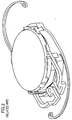
- the MC-IOL also includes projections (or haptics) 11 and 13 which securely hold the MC-IOL in the tissue of the human eye.
- the above-described structure permits the base intraocular lens 10 to form a platform upon which the mid lens 20 is placed, and to hold the top lens 30.
- the MC-IOL replaces the crystalline lens of the human eye. Once a patient's eye has healed after such a surgery, the surgeon reenters the eye and replaces, if necessary, and more than once, the top lens 30 and the mid lens 20 to modify the optical characteristics of the eye until the desired levels for each optical characteristic are attained.
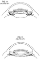
- the C-IOL can also be used with a conventional IOL, as well as with an accommodating IOL, and mounted in the sulcus ( FIG. 8 ), in the anterior chamber angle ( FIG. 9 ), in the anterior chamber with posterior chamber fixation ( FIG. 10 ) or in the anterior chamber with iris fixation ( FIG. 11 ).
- a surgeon modifies the optical characteristics of the optical system of the eye by using the mid and top lenses in tandem with the preexisting conventional IOL implant or crystalline lens of the eye.
- the C-IOL and MC-IOL provide numerous enhanced features.
- the C-IOL and MC-IOL can each be structured as a monofocal or multifocal optical system, correct astigmatism, as well as comprise ultraviolet light-absorbing, tinted, or other such chemically treated materials.
- an adjustable MC-IOL or C-IOL is more desirable than a single component implant.
- MC-IOL multiple components
- an inventory of about one hundred components would be necessary.
- anterior chamber lenses progressive encapsulation or engulfment of the lens haptics by uveal tissue in the angle often occurs 1-2 years post-operatively. The engulfment typically makes the removal of the lenses and their haptics more difficult.
- Exchange of iris fixated anterior chamber lenses does not typically guarantee precise position or orientation. Posterior chamber lenses similarly cannot be removed because of posterior capsule fibrosis. Easy removal and exchangeability is critical for any customized emmetropic system, which can be provided by a specially designed multicomponent lens system.
- a MC-IOL having three elements rather than one permits refractive customization and adjustability for all refractive errors, as well as for all patients, while using a minimal number of lens elements or parts and requiring little customization on the part of the manufacturer.
- a single component intraocular lens which in general is not designed to be removed and with only two optical surfaces, cannot accurately allow for compensation of sphere, cylinder, cylindrical axis, and all forms of optical aberrations that may be discovered after the initial implantation.
- the MC-IOL typically will have four removable optical surfaces which can compensate for these optical properties.
- the inventor of this application invented the previously discussed MC-IOL and C-IOL that are designed specifically to permit the easy exchange of optical elements at a post-operative period without risk to the human eye or to the patient, beyond the risk of ordinary intraocular surgery.
- the easy exchangeability of optical elements is critical because the actual surgery of implanting the lens in the first place, as well as variances in the manner in which the eye heals after implantation, potentially create distortions which may not stabilize for several months after the operation. Therefore, the ability to measure and to compensate for the distortion(s) optimally takes place several months after surgery and cannot typically be predicted prior thereto. Since the same surgical wound is used for both the primary and secondary operations, additional distortion due to wound healing would not be anticipated as a result of the second operation.
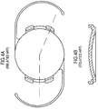
- the MC-IOL has four surfaces available for modification, two plano and two convex.
- the modification is made only to the plano surfaces to avoid interfering with the convex side which may already be used for correction of astigmatism (cylinder) or used as a multifocal lens surface.
- cylinder astigmatism
- multifocal lens surface The same preference applies to the CIOL, which has two surfaces available for modification, one plano and the other convex.
- any time incisions are made to the cornea the cornea loses some of its natural globularity due to imperfections caused by the incisions and the resultant trauma.
- the imperfections in the cornea lead to induced astigmatism, or optical aberrations caused by irregularities in the shape of the cornea.
- a surgeon may also minimize the amount of induced astigmatism. Even though the three-component design simplifies the process of correcting induced astigmatism, minimizing the amount of induced astigmatism remains a primary goal for all intraocular surgeries.
- US-A-2004236422 discloses an intraocular lens in accordance with the preamble of claim 1.
- An embodiment of the present invention includes a multi-component intraocular lens, wherein the base lens is attached with haptics, and the top and mid lenses are assembled outside the eye.
- the top and mid lenses may include projections designed to lock into place with flanges of the base lens.
- the intraocular lens system allows assembly without the use of special equipment or techniques for securing the top and mid lenses to the base lens.
- the intraocular lens system also does not require that the surgeon performing the operation be able to see or visualize the insertion of the top and mid lenses. Rather, in the present invention, the surgeon merely slides the folded mid/top lens assembly into the eye, unfolds the assembly in the eye, and slides the assembly across the base lens component until each projection aligns with a corresponding flange.
- the foldable removable lens component is attached to the foldable mid intraocular lens component by a notch along the circumference of the foldable removable lens component.
- an adjustable intraocular lens allows adjustment or exchange of optical elements, both spherical and cylindrical, independent of any additional wound healing or significant calculation error to fine-tune, reverse, or replace any of the original optical features.
- the top lens is then placed on the base lens and the mid lens arranged on the top lens such that the mid lens is most anterior relative to the patient's eye and the top lens is arranged between or in the middle of the base and mid lens.
- the mid lens includes a notch with which a projection of the top lens engages to securely maintain the mid/top lens assembly
- another embodiment of the instant application provides the top and mid lenses being joined to each other by a joining means, such as, for example, a medical adhesive that is applied in at least one location where the mid lens interfaces with the top lens.
- the present invention includes a feature wherein the haptic of the mid lens has projections extending anteriorly and posteriorly that capture the top lens (circular configuration) and retain the top and mid lens (circular configuration) as an optical assembly.
- the dual direction extending projections allow the surgeon or manufacturer the ability to orient the components independently at each of 360° orientations.
- Each of the circular components i.e., the mid lens and top lens
- the present invention includes an embodiment wherein the mid and top lenses are integrated into a single component such that an adhesive or other such joining mechanism is not necessary to join the mid and top lenses together.
- the front lens or optical assembly can be custom manufactured into a single piece for each patient to correct sphere cylinder presbyopia, spherical aberrations, and higher order aberrations
- the intraocular lens system of the present invention allows assembly without the use of special equipment or techniques for securing the top and mid lenses together.
- FIG. 12A shows a top or plan view of the intraocular foldable base lens 100 in a preferred embodiment of the present invention.
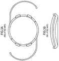
- the base lens 100 is similar to the MC-IOL base lens illustrated in Fig. 3 .
- the base lens 100 is preferably manufactured from acrylic or silicone materials, but the base lens 100 can be manufactured from any suitable foldable material.
- the base lens 100 has a diameter ranging from 1.00 to 8.00 millimeters, but preferably is between 5.50 and 6.50 millimeters, and has an optical aperture ranging from 3.0 millimeters to 7.0 millimeters, with a preferable optical aperture of 5.5 millimeters.
- the base lens 100 has a diameter ranging from 1.00 to 8.00 millimeters, and is preferably composed of foldable material. Accordingly, the insertion of the base lens 100 into the eye requires an incision therein which is less than half as large as the diameter of the base lens 100.
- the base lens 100 attaches to the eye by at least one haptic 120.
- the base lens 100 is secured to the eye by at least one, but preferably two haptics 120, however, this is merely one embodiment of the present invention, and other embodiments may use one or more haptics 120 to secure the base lens 100 to the eye.
- the base lens 100 can also include one or more flanges 105 disposed on and extending outwardly away from the body of the base lens 100, preferably forming a perpendicular angle with the plane of the base lens, however the flanges 105 extend outward from the body of the base lens at any angle from 45 degrees to 135 degrees.
- two flanges 105 are disposed on either side of the base lens 100.
- the invention is not limited to this embodiment, as more flanges 105 may be disposed in various locations around the base lens 100.
- Each flange 105 has a slot 110 designed or configured to receive or accept an assembly of a top lens 300 and a mid lens 200 therein, which will be described in more detail herein.
- the slot 110 illustrated in FIG. 12B is in the shape of a parallelogram, however other shaped slots, such as elliptical, oval, trapezoidal, rounded rectangular, or any other known geometric shape are considered to be within the scope and pervue of the present invention.
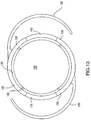
- the base lens incorporated into another embodiment of the present invention is illustrated in FIG. 13 .
- the base lens 102 is similar to the base lens 100, except for a groove 130 defined in the base lens 100 and extending along the entire outer periphery of the base lens 102, and four attachment points 140, which serve to attach the optical region 150 to the base lens 102. Although four attachment points 140 are illustrated here, embodiments with more attachment points or fewer attachment points are also considered to be within the scope and pervue of the invention. In all other aspects, the base lens 102 is the same as the base lens 100 illustrated in FIGS. 12A and 12B .
- the base lens 100 is infused with chromophores, which absorb light in a portion of the light spectrum.
- the base lens could be infused with chromophores to absorb light from the ultraviolet wavelength portion of the light spectrum, typically between 380 and 389 nm.
- the intraocular lens system reduces eye glare, enhances vision capabilities, and helps protect the eye from potentially harmful ultraviolet rays.
- ultraviolet light is exemplified here, other color chromophores, which are used to block other wavelengths of light, are also considered within the scope and pervue of the invention.
- the foldable MC-IOL includes two or more additional refractive components, including an assembly of the top lens 300 and the mid lens 200, described more fully herein.
- One embodiment of the mid lens 200 hereinafter interchangeably referred to as the "middle" lens, the "cap” lens, or the “removable component” lens, is illustrated in FIGS. 14A and 14B .
- the mid lens 200 allows spherical adjustments from -4.00 D to +4.00 D in 0.25 D increments.
- the top lens 300 carries the astigmatic correction, which can range, for example, from 0.00 D to 5.00 D cylinder in 0.25 D increments and has an orientation projection 305.
- the present values are presented merely for illustrative purposes, and other possible ranges for the cylinder at various sphere values are considered to be within the scope and pervue of the invention.
- the mid lens 200 and/or the top lens 300 may serve multiple purposes depending on the specific embodiment and the specific nature of the problem to be solved.
- the top lens 300 and/or the mid lens 200 may correct myopia, presbyopia, or astigmatism.
- the top lens 300 and/or the mid lens 200 may also be used to correct cosmetic defects in the eye.
- the top lens 300 and/or the mid lens 200 may also be tinted to protect the eye from ultraviolet rays, or blue light, or to reduce glare, or to change the color of the eye for cosmetic or other purposes.
- the top lens 300 and/or the mid lens 200 may be used to deliver pharmacological compounds, such as medicines, into the eye.
- the top lens 300 and/or the mid lens 200 in this embodiment feature a system for delivering a compound into the eye over a predetermined period of time.
- the surgeon removes the top lens 300 and/or the mid lens 200, and replaces the top lens 300 and/or the mid lens 200 with a new lens for delivering a compound into the eye, if needed.
- the patient may conveniently receive delivery of a compound directly into the inner portions of the eye, while minimizing the risk to the patient, and simplifying the delivery of the compound. Because this treatment does not require recurring action by the patient, the treatment avoids the problem of patient non-compliance, which is critically important to the treatment of chronic eye disorders, such as glaucoma, diabetes, and macular degeneration.
- FIG. 14A illustrates a top view of the mid lens 200 of an embodiment of the present invention.
- the mid lens 200 includes one or more projections 210 extending horizontally from the body of the mid lens 200, preferably in the plane parallel to the edge of the mid lens 200, but optionally at any angle from 150 to 180 degrees in either direction.
- Each projection 210 may extend outward from the lens ranging from 0.5 to 5.0 millimeters from the outer edge of the mid lens 200.
- Each projection 210 may also have varying lengths depending on the shape and number of projections. The projections are illustrated in Fig.
- any shape which would accomplish the stated purpose of fitting into slot 110 of the flange 105 extending from the base lens 100 is considered to be within the scope and pervue of the present invention.
- any shape, indentation, marking, notching, or surface treatment of the flange 105 including, for example, ribbing, roughening, adding bumps, notches, and indentations, are considered to be within the scope and prevue of the present invention.
- any adhesive material on the flange for example, glues, Velcros, cements, resins, pastes, or any other adherent, is also considered to be within the scope and pervue of the present invention.
- the lip 225 may also optionally be surface treated to have at least one of bumps, ridges, bevels, serrated teeth, gouges, notches, impressions, recesses, or other such surface treatments that are suitable for use in a notch. Additionally, although the notch 230 is illustrated as substantially defining a right angle between the side portion 250 and the lip 225, the angle formed between the notch 230 and the lip 225 may range from 45 degrees to 135 degrees.
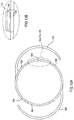
- the top lens 300 Prior to insertion into the eye, the top lens 300 (described further herein with respect to FIG. 15 ) engages the notch 225, such that a seal is formed between the notch 225 and the top lens 300, and which holds the mid lens 200 and the top lens 300 together as a single assembly.
- the top lens 300 includes a groove 320 defined in a surface of the top lens 300, and extends along the circumference of the outer periphery of the top lens 300.
- the groove 320 extends along the circumference of the top lens 300, except for the location of the compression slots 315, as shown in FIG. 15 .
- four compression slots 315 are illustrated here, embodiments with more compression slots or fewer compression slots are also considered to be within the scope and pervue of the invention.
- the top lens 300 also includes one or more end notches 305.
- end notches 305 are illustrated, but varying numbers of end notches, or no end notches at all, are considered to be within the scope of the invention.
- the end notches 305 are raised slightly from the surface of the top lens 300, and can be configured to be any one of notches, bumps, ridges, or indentations. The notches could also be of various shapes, sizes, and lengths.
- the top lens 300 is oriented so that, when the top lens 300 is inserted into the mid lens 200, as discussed below, the raised projections or notches 305 face the mid lens 200 or may also project away from the mid lens 200.
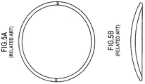
- the notches or projections 305 can provide directional and axial orientation for the top lens, similar to the axis orientation marks 85 of FIG. 5 .
- FIG. 16 A side view of the completed assembly of the top lens 300 and the mid lens 200 is illustrated in FIG. 16 . It is noted that in FIG. 16 , the angles and sizes have been exaggerated in order to illustrate the relationship between the top lens 300 and the mid lens 200. It is also noted that, although in FIG. 16 , the side portion of top lens 300 is flush with the side region 250 of the mid lens 200, and the bottom portion of top lens 300 is flush with the top portion of the mid lens 200, this fitting is not required for the assembly of the top lens 300 and mid lens 200. That is, embodiments in which the side portion of the top lens 300 is not flush with side region 250 of the mid lens are considered to be within the scope and pervue of the invention.
- the surgeon inserts the top lens 300 and the mid lens 200 assembly into the base lens 100 by sliding a projection 210 into a slot 110 of a corresponding flange 105 of the base lens 100.
- projection 210 is designed to slide into place with the slot 110. That is, the surgeon unfolds the assembly of the top lens 300 and the mid lens 200, and then slides the assembly across the base lens 100 until a first projection 210 lines up with a first slot 110.
- the surgeon may perform a disassembly procedure as discussed herein.
- a cannula containing visco elastic material would be introduced into the eye and positioned at the interface between the lens assembly (mid lens 200 and top lens 300) and the base lens 100.
- the injection of visco elastic causes the mid 200/top 300 lens assembly to elevate, thus disengaging the projections 210 from the slots 110 in the base lens 100.
- the original lens assembly would then be removed from the eye, and a new lens assembly placed into the eye and attached to the base lens 100 similar to as described above in the primary operation.
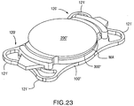
- the fully assembled or end appearance of a base lens 100' compared to the base lens 100 (102) described above and illustrated in FIGS. 12A, 12B and 13 is substantially similar to the base lens 100 (102). Therefore, a detailed description of many of the common features of the base lens 100' with the base lens 100 (102) is omitted herefrom in order to avoid redundancy.
- the base lens 100' differs from the above-described base lens 100 (102) in that the base lens 100' is initially manufactured to be in three components that are to be assembled together and haptics 120' in the base lens 100' are configured to be a plate shape haptic 120' as opposed to the C-loop haptic 120 in the above-described base lens 100 (102).
- the plate shaped hepatic 120' ( FIG. 24 ) is configured to have ears 121', 121' which are enveloped and retained by the eye tissues of the patient.
- the flange 105' to be held in the notch 101' by other conventional and well-known techniques for joining two components of an apparatus, such as, for example only, placing an adhesive or glue in discrete locations along a perimeter of the notch 101' or along the entire perimeter of the notch 101' to join the flange 105' to the base lens 100' at the notch 105', or using a laser to join the flange 105' to the base lens 100', or ultrasonically welding the flange 105' and base lens 100' together, or any other suitable technique that is now known or later developed.
- the slot 110' to be formed in the flange 105' by cutting the opening of the slot 110' using a laser.
- the foldable MC-IOL according to this embodiment includes two or more additional refractive components, including an assembly of a mid lens 300' and a top lens 200', described more fully herein. It should be noted that the top lens 300 and the mid lens 200 of the previously described embodiment ( FIGS 12A - 16 ) are similar to the mid lens 300' and top lens 200' described below, with the exception of certain key differences.
- FIGS. 17A - 25 A key difference between the previous embodiment of FIGS. 12A - 16 and the currently described embodiment ( FIGS. 17A - 25 ) is the orientation of the top lens 300 and the mid lens 200.
- the mid lens 200 was disposed between the base lens 100 and the top lens 300.
- the top lens 300 is now the mid lens 300' and the mid lens 200 is now the top lens 200'.
- top lens 200' is illustrated in FIGS. 18A and 18B .
- the top lens 200' allows spherical adjustments from -4.00 D to +4.00 D in 0.25 D increments.
- the mid lens 300' carries the astigmatic correction, which can range, for example, from 0.00 D to 5.00 D cylinder in 0.25 D increments and has an orientation projection 305.
- the present values are presented merely for illustrative purposes, and other possible ranges for the cylinder and the sphere values are considered to be within the scope and pervue of the invention.
- the mid lens 300' may be constructed from acrylic, silicone, or any other material suitable for manufacturing a foldable intraocular lens.
- the mid lens 300' has a central thickness ranging from 0.1 millimeters to 0.4 millimeters, and a diameter ranging from 1.50 to 8.50 millimeters, but preferably is between 5.50 and 7.00 millimeters.
- the mid lens 300' features an optical aperture ranging from 3.0 millimeters to 7.0 millimeters, with a preferable optical aperture of 5.5 millimeters.
- the mid lens 300' and/or the top lens 200' may be designed to change the light-gathering aspects of the eye to improve night vision.
- a lens with these characteristics has potential use for military applications, such as low light or telescopic use, or for underground workers, or in any other application where the patient desires reversibly enhanced night vision, or vision enhancement in a specific area of the spectrum.
- military applications such as low light or telescopic use, or for underground workers, or in any other application where the patient desires reversibly enhanced night vision, or vision enhancement in a specific area of the spectrum.
- athletes such as baseball players may desire amber-tinted lenses to improve their ability to perform the tasks critical to their sport, such as seeing the ball.
- Lenses designed for this purpose could be removed when the patient no longer desires the enhanced vision characteristic, for example when the military application is finished, or the athlete's season or career ends.
- the mid lens 300' and/or the top lens 200' may be used to deliver pharmacological compounds, such as medicines, into the eye.
- the mid lens 300' and/or the top lens 200' in this embodiment feature a system for delivering a compound into the eye over a predetermined period of time. At the end of the predetermined time period, the surgeon removes the mid lens 300' and/or the top lens 200', and replaces the mid lens 300' and/or the top lens 200' with a new lens for delivering a compound into the eye, if needed.
- the patient may conveniently receive delivery of a compound directly into the inner portions of the eye, while minimizing the risk to the patient, and simplifying the delivery of the compound. Because this treatment does not require recurring action by the patient, the treatment avoids the problem of patient non-compliance, which is critically important to the treatment of chronic eye disorders, such as glaucoma, diabetes, and macular degeneration.
- FIG. 18A illustrates a top view of the top lens 200' of an embodiment of the present invention.
- the top lens 200' includes one or more projections 210 extending horizontally from the body of the top lens 200', preferably in the plane parallel to the edge of the top lens 200', but optionally at any angle from 150 to 180 degrees in either direction.
- Each projection 210 may extend outward from the lens ranging from 0.5 to 5.0 millimeters from the outer edge of the top lens 200'.
- Each projection 210 may also have varying lengths depending on the shape and number of projections.
- the projections 210 are illustrated in Fig.
- any shape which would accomplish the stated purpose of fitting into slot 110' of the flange 105' extending from the base lens 100' is considered to be within the scope and pervue of the present invention.
- any shape, indentation, marking, notching, or surface treatment of the flange 105' including, for example, ribbing, roughening, adding bumps, notches, and indentations, are considered to be within the scope and pervue of the present invention.
- any adhesive material on the flange for example, glues, Velcros TM , cements, resins, pastes, or any other adherent, is also considered to be within the scope and pervue of the present invention.
- the medical adhesive MA Prior to insertion into the eye, the medical adhesive MA is applied to the inner surface 250a of the top lens 200'. It should be noted that the medical adhesive MA may be applied to completely cover the entire surface area of the inner surface 250a as will be described in further detail below, or less than the entire surface area. The minimum amount of medical adhesive to be applied to the inner surface 250a should be sufficient to securely retain the mid lens 300' in the top lens 200'.
- the medical adhesives MA may be selected from one of a group including cyanoacrylate adhesives, which may be applied with or without cyanoacrylate accelerators and primers, light cure acrylics, light cure cyanoacrylates, light cure silicones, epoxy adhesives, and any other adhesive that is suitable for the present invention. Although not a requirement, it is preferable that whichever adhesive is selected, that the medical adhesive MA be capable of curing under either UV or visible light sources and respond to low, medium or high intensity light.
- the mid lens 300' of the current embodiment includes a groove 320 defined in a surface of the mid lens 300', and extends along the circumference of the outer periphery of the mid lens 300'.
- the groove 320 extends along the circumference of the mid lens 300', except for the location of the compression slots 315, as shown in FIG. 19 .
- compression slots 315 are illustrated here, embodiments with more compression slots or fewer compression slots are also considered to be within the scope and pervue of the invention.
- Groove 320 and a series of compression slots 315 allow for an easier engagement of the mid lens 300' with the top lens 200'.
- the groove 320 could be replaced with other slots or channels defined in the periphery of the lens, and the invention should not be considered to be limited to this specific embodiment.
- the mid lens 300' also includes one or more end notches 305.
- end notches 305 are illustrated, but varying numbers of end notches, or no end notches at all, are considered to be within the scope of the invention.
- the end notches 305 are raised slightly from the surface of the mid lens 300', and can be configured to be any one of notches, bumps, ridges, or indentations. The notches could also be of various shapes, sizes, and lengths.
- the mid lens 300' is oriented so that, when the mid lens 300' engages the top lens 200', the raised projections or notches 305 face the top lens 200' or may also project away from the top lens 200' and toward the base lens 100.
- the notches or projections 305 can provide directional and axial orientation for the mid lens, similar to the axis orientation marks 85 of FIG. 5 .
- the surgeon performing the operation or the lens manufacturer assembles the top lens 200' and the mid lens 300' outside the eye to a predetermined axis orientation to correct the astigmatism, and then inserts the completed assembly into the eye as one folded piece.
- a side view of the completed assembly of the top lens 200' and the mid lens 300' is illustrated in FIG. 20 . It should be noted that unlike the assembly shown in FIG.
- the arrangement order of the mid lens 300' and the top lens 200' assembly of the current embodiment is reversed such that the mid lens 300', which is the top lens 300 in the previously described embodiment, is not the mid lens 300' of the present embodiment, wherein the mid lens 200 of the previous embodiment is the top lens 200', such that the arrangement order of the present embodiment is base lens 100, mid lens 300' and top lens 200'.
- FIG. 20 the sizes have been exaggerated in order to illustrate the relationship between the side surfaces 350a and 250a, respectively, of the mid lens 300' and the top lens 200'. It is also noted that, although in FIG. 20 , the side surface 350a of the mid lens 300' is flush with the side surface 250a of the top lens 200', and the top portion of mid lens 300' is flush with the bottom portion of the top lens 200', this fitting is not required for the assembly of the mid lens 300' and top lens 200'. That is, embodiments in which the side surface 350a of the mid lens 300' is not flush with side surface 250a of the top lens 200' are considered to be within the scope and pervue of the invention.
- FIG. 21 illustrates an exploded view of another embodiment of the present invention wherein the medical adhesive MA is administered along an entire upper surface of the mid lens 300" and/or an entire lower surface of the top lens 200" which directly opposes the upper surface of the mid lens 300".
- the mid lens 300" is provided with at least one projection for engaging the slot 110' formed in the flange 105' of the base lens 100' and, as such, the outer circumferential surface of the top lens 200" has a constant diameter.
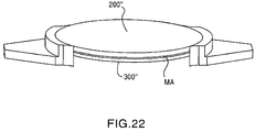
- FIG. 22 illustrates an assembled state of the top lens 200" and the mid lens 300" with the medical adhesive MA joining the two lenses 200" and 300" together into a front lens assembly. As shown in FIG.
- the front assembly (200" and 300") is then assembled with the base lens 100" which, in this embodiment, has the plate shaped haptic 120', wherein each haptic 120' has at least one pair of the previously discussed dog ears 121', 121'.
- the surgeon inserts the mid lens 300' (300") and the top lens 200' (200") assembly into the base lens 100' by sliding a projection 210 into a slot 110' of a corresponding flange 105' of the base lens 100'.
- the surgeon does not need to visually see the individual pieces line up together. Instead, the projection 210 is designed to slide into place with the slot 110'.
- the surgeon unfolds the assembly of the mid lens 300' (300") and the top lens 200' (200"), and then slides the assembly across the base lens 100' until a first projection 210 lines up with a first slot 110'. Once a projection 210 lines up with a slot 110', the projection 210 catches in the slot 110', and the surgeon will feel the two pieces lock into place. Once the first projection 210 is in place in the corresponding first slot 110', if more projections are present in the top lens 200' (200"), the surgeon adjusts the top lens 200' (200") and the mid lens 300' (300") until the other projection(s) 210 line up with the other slot(s) 105'. Once all projections 210 have been inserted into their corresponding slots 110', the assembly of the mid lens 300' and the top lens 200' is secured in the base lens 100', and the procedure is completed.
- the mid lens 200 or the top lens 200' (200") may also have additional spherical power ranging from -9.50 D to 9.50 D in 0.25 D increments, and may be either monofocal or multifocal.
- the top lens 300 or the mid lens 300' (300") may also be constructed from acrylic, silicone, or any other material suitable for crafting a foldable intraocular lens.
- the mid lens 200 or the top lens 200' (200") has a plano-convex lens with a central thickness ranging from 0.1 to 0.3 millimeters, and a diameter ranging from 1.5 to 8.5 millimeters, preferably between 6.0 and 6.5 millimeters, and an optical clear aperture ranging from 5.0 to 6.0 millimeters, preferably 5.5 mm.
- the mid lens 200 or the top lens 200' (200") may also be manufactured in a manner to allow absorption of light in the ultraviolet wavelength portion of the light spectrum, or other portions of the light spectrum for which it may be clinically important to absorb light, such as the blue light portion.
- the mid lens 200 or the top lens 200' (200") may have at least one bevel 210 formed along an outer edge thereof, allowing the mid lens 200 or the top lens 200' (200") to fit into the opening 110 of the base lens 100 or 100'.
- the three piece system (i.e. the base lens 100 or 100', the top lens 300 or the mid lens 300' or 300", and the mid lens 200 or the top lens 200', 200") described herein has a spherical power range of -20.00 D to +40.00 D and accuracy of +/- 0.25 D.
- the three piece system has an adjustable cylindrical power of 5.00 D, and adjustable spherical power of +/- 9.00 D. Its maximum central thickness is 1.88 millimeters, but could be as thick as 4.0 millimeters.
- the optical element diameter ranges from 1.00 millimeters to 8.00 millimeters.
- the optical aperture ranges from 3.0 to 7.0 millimeters, with an optimal optical aperture of 5.5 millimeters.
- a telescopic lens can be introduced into the lens system for the treatment of macular degeneration. If the base lens 102 illustrated in FIG. 13 is used, then the surgeon can cut the attachment points 140 while the lens is in the eye, and remove the central optic 150 of the base lens 102. The surgeon can then implant a telescopic assembly, for example a Lipschitz telescopic assembly, in place of the optic portion of the base lens 102, to allow optical correction for macular degeneration.
- a telescopic assembly for example a Lipschitz telescopic assembly
- Optical aberrations and abnormalities present after implantation of the intraocular lens are identified by measuring the optical system using, for example, wave front technology.
- a surface modifier may be used to modify either a surface of the eye itself, or a component of the intraocular lens system. If a component requires modification or replacement, the surgeon can remove the component, alter the component or replace it with another, and reinsert the component through the same wound which was used to implant the lens. This process is described more fully in U.S. Patent No. 6,413,276 , "Modified Intraocular Lens and Method of Correcting Optical Aberrations Therein," by the same inventor.
- the mid lens (300', 300") and top lens (200', 200") assembly can be prefabricated as a singe component or lens 500 that incorporates the two lenses as a single unit.
- the single component or lens 500 would preferably be manufactured to the patient's prescription and the lens 500 inserted into the base lens 100' as shown in FIG. 25 . That is, the embodiment shown in FIG. 24 does not require the medical adhesive MA between the mid lens 300', 300" and the top lens 200', 200" because the mid and top lenses are integrated together to form the single piece lens 500.
- the lens assemblies include at least one axis orientation mark 185 provided therein that provide the surgeon with assistance in terms of directional and axial orientation of the mid lens 300', 300" or lens 500 during the insertion procedure.
Landscapes
- Health & Medical Sciences (AREA)
- Ophthalmology & Optometry (AREA)
- Cardiology (AREA)
- Oral & Maxillofacial Surgery (AREA)
- Transplantation (AREA)
- Engineering & Computer Science (AREA)
- Biomedical Technology (AREA)
- Heart & Thoracic Surgery (AREA)
- Vascular Medicine (AREA)
- Life Sciences & Earth Sciences (AREA)
- Animal Behavior & Ethology (AREA)
- General Health & Medical Sciences (AREA)
- Public Health (AREA)
- Veterinary Medicine (AREA)
- Prostheses (AREA)
Claims (35)
- Mehrteilige, in ein optisches System eines menschlichen Auges implantierbare Intraokularlinse umfassend:eine Basislinse (100, 100') mit einer vorderen Oberfläche, die ausgebildet ist, um einer Vorderseite des menschlichen Auges zugewandt zu sein, eine auf einer relativ zur vorderen Oberfläche gegengesetzten Seite der Basislinse (100, 100') angeordneten hinteren Oberfläche, die ausgebildet ist, um einer Rückseite des menschlichen Auges zugewandt zu sein, eine umlaufende Umfangsseitenfläche, die die vordere und hintere Oberfläche verbindet, und mindestens eine Haptik (120), die sich von der Umfangsseitenfläche weg erstreckt und zum Befestigen der Basislinse (100, 100') innerhalb des Gewebes des menschlichen Auges ausgebildet ist, wobei die Basislinse (100, 100') aus einem ersten faltbaren Material hergestellt ist; undeine optische Baugruppe, die in die Basislinse eingreift, wobei die optische Baugruppe aus einem zweiten faltbaren Material hergestellt ist,wobei die Basislinse (100, 100') mindestens einen auf der vorderen Oberfläche der Basislinse (100, 100') angeordneten Flansch (105, 105') umfasst, wobei der mindestens eine Flansch (105, 105') eine darin definierte Aussparung (110, 110') umfasst, wobei die Aussparung ausschließlich über der vorderen Oberfläche der Basislinse (100, 100') angeordnet ist; undwobei die optische Baugruppe parallel zur Vorderseite der Basislinse (100, 100') oberhalb der vorderen Oberfläche der Basislinse (100, 100') in die Aussparung eingreift, dadurch gekennzeichnet, dass der mindestens eine Flansch sich von der vorderen Oberfläche der Basislinse (100, 100') in Richtung der Vorderseite des menschlichen Auges in einem Winkel zwischen 45 Grad und 135 Grad wegerstreckt, und dass die optische Baugruppe in die Aussparung (110, 110') oberhalb der mindestens einen Haptik (120) eingreift.
- Intraokularlinse gemäß Anspruch 1, wobei die faltbare optische Baugruppe mindestens einen sich davon wegerstreckenden Vorsprung (210) aufweist und wobei der Vorsprung ausgebildet ist, um in die Aussparung (110) des mindestens einen Flansches der Basislinse (100, 100') parallel zur vorderen Oberfläche der Basislinse und oberhalb der mindestens einen Haptik (120) einzugreifen.
- Intraokularlinse gemäß Anspruch 1, wobei die faltbare optische Baugruppe umfasst:eine Oberlinse (300), undeine Mittellinse (200), die lösbar in die Oberlinse eingreift.
- Intraokularlinse gemäß Anspruch 3, wobei die Mittellinse (200) eine sich L-förmig nach oben und von einer ebenen Oberfläche der Mittellinse wegerstreckende Lippe (225) umfasst und wobei eine Nut (230) durch die Lippe und die ebene Oberfläche definiert ist.
- Intraokularlinse gemäß Anspruch 4, wobei die Oberlinse (300) durch die Lippe (225) in der Mittellinse (200) befestigt ist.
- Intraokularlinse gemäß Anspruch 4, wobei mindestens eine Seite der Lippe abgeschrägt ist.
- Intraokularlinse gemäß Anspruch 6, wobei die Nut (230) in einen äußeren Umfang der Oberlinse (300) eingreift.
- Intraokularlinse gemäß Anspruch 3, wobei mindestens ein Vorsprung (210) sich von der Mittellinse aus erstreckt und wobei der mindestens eine Vorsprung zum Eingreifen in die im mindestens einen sich von der Basislinse (100, 100') erstreckenden Flansch definierte Aussparung ausgebildet ist.
- Intraokularlinse gemäß Anspruch 1, wobei die Basislinse (100, 100') mindestens eine Sichtkorrekturkomponente hat.
- Intraokularlinse gemäß Anspruch 3, wobei mindestens die Mittellinse (200) oder die Oberlinse (300) mindestens eine Sichtkorrekturkomponente aufweist.
- Intraokularlinse gemäß Anspruch 1, wobei die Basislinse (100') mindestens eine in einem Seitenabschnitt der Basislinse (100') definierte Nut (101') umfasst und wobei der Flansch (105') zum Eingreifen in die Nut (101') ausgebildet ist, um den Flansch an der Basislinse zu halten.
- Intraokularlinse gemäß Anspruch 11, wobei der Flansch (105') in die Nut (101') der Basislinse (100') entweder durch einen an separaten Stellen zwischen dem Flansch und der Nut angeordneten Klebstoff, einen Laser, Ultraschallschweißen oder einer Schnappverschlussanordnung gesichert eingreift.
- Intraokularlinse gemäß Anspruch 11, weiter umfassend mindestens eine auf dieser angeordnete Achsenorientierungsmarkierung.
- Intraokularlinse gemäß Anspruch 11, wobei die optische Baugruppe eine erste Linse umfasst, die mit einer zweiten Linse verbunden ist.
- Intraokularlinse gemäß Anspruch 14, wobei die erste Linse eine Oberlinse (300) und die zweite Linse eine Mittellinse (200) ist.
- Intraokularlinse gemäß Anspruch 15, wobei ein medizinischer Klebstoff die Oberlinse (300) und die Mittellinse (200) miteinander verbindet.
- Intraokularlinse gemäß Anspruch 16, wobei der medizinische Klebstoff über mindestens einer äußeren Umfangsfläche der Oberlinse (300) oder einer der äußeren Umfangsfläche der Oberlinse (300) gegenüberliegenden inneren Umfangsfläche (250a) der Mittellinse (200) aufgebracht ist.
- Intraokularlinse gemäß Anspruch 16, wobei der medizinische Klebstoff über mindestens eine Oberseite der Oberlinse (300) oder eine der Oberseite der Oberlinse (300) gegenüberliegende Unterseite der Mittellinse (200) aufgebracht ist.
- Intraokularlinse gemäß Anspruch 15, wobei die Mittellinse (200) eine astigmatische Korrektur und die Oberlinse (300) eine sphärische Korrektur realisiert
- Intraokularlinse gemäß Anspruch 8, wobei die Oberlinse (300) zwischen der Mittellinse (200) und der Basislinse (100) angeordnet ist.
- Intraokularlinse gemäß Anspruch 15, wobei entweder die Oberlinse (300) oder die Mittellinse (200) mindestens einen sich von einer äußeren Umfangsfläche wegerstreckenden Vorsprung (210) aufweist und welcher ausgebildet ist, um in die im Flansch (105') der Basislinse (100') definierte Aussparung (110') einzugreifen.
- Intraokularlinse gemäß Anspruch 16, wobei der medizinische Klebstoff aus einer Gruppe ausgewählt ist, umfassend Cyanacrylatklebstoffe, lichthärtende Acryle, lichthärtende Cyanacrylate, lichthärtende Silikone und Epoxidklebstoffe.
- Intraokularlinse gemäß Anspruch 1 oder 11, wobei die im Flansch (105') der Basislinse definierte Aussparung (110') eine Form hat, die aus einer Gruppe ausgewählt ist, umfassend eine Ellipse, ein Oval, ein Trapez, ein abgerundetes Rechteck, ein Parallelogramm, ein Fünfeck, ein Sechseck und ein Achteck.
- Intraokularlinse gemäß Anspruch 1 oder 21, wobei die mindestens eine Ausnehmung (210) oberflächenbehandelt ist, ausgewählt aus einer Gruppe umfassend: gekerbt, geschlitzt, gerillt, gerieft, aufgeraut, gerippt, ausgebohrt, geritzt, gezogen, gefurcht, gewellt, gequetscht oder kanneliert.
- Intraokularlinse gemäß Anspruch 3 oder 15, wobei die mindestens die Oberlinse (300) oder die Mittellinse (200) mit einem vorbestimmten Zylinder und Dioptrienwert ausgebildet ist, um Astigmatismus zur korrigieren.
- Intraokularlinse gemäß Anspruch 3 oder 15, wobei die mindestens die Oberlinse (300) oder die Mittellinse (200) eine Beschichtung umfasst, die einen Bereich von Wellenlängen blockieren oder absorbieren kann.
- Intraokularlinse gemäß Anspruch 3 oder 15, wobei mindestens entweder die Oberlinse (300) oder die Mittellinse (200) eine getönte Beschichtung aufweist, die die Fähigkeit des menschlichen Auges verbessert, gefilterte Bereiche eines Lichtspektrums zu sehen.
- Intraokularlinse gemäß Anspruch 1 oder 11, wobei das erste faltbare Material das gleiche wie das zweite faltbare Material ist.
- Intraokularlinse gemäß Anspruch 1 oder 11, wobei das erste faltbare Material sich vom zweiten faltbaren Material unterscheidet.
- Intraokularlinse gemäß Anspruch 11, wobei die optische Baugruppe mindestens einen von einer äußeren Umfangsfläche wegerstreckenden Vorsprung (210) aufweist, der ausgebildet ist, um in die im Flansch der Basislinse (100, 100') definierte Ausnehmung (110, 110') einzugreifen.
- Intraokularlinse gemäß Anspruch 11, wobei der mindestens eine Vorsprung zwei Vorsprünge (210) aufweist, einen ersten Vorsprung, der sich in eine erste Richtung erstreckt und einen zweiten Vorsprung, der sich in eine zweite Richtung erstreckt, die sich von der ersten Richtung unterscheidet.
- Intraokularlinse gemäß Anspruch 11, wobei die optische Baugruppe aus einer einzelnen Komponente besteht.
- Intraokularlinse gemäß Anspruch 32, wobei die eine einzelne Komponente mindestens einen der Kugel-, Zylinder-, Alterssichtigkeits-, sphärischen Abbildungsfehler oder übergeordnete optische Abbildungsfehler korrigiert.
- Intraokularlinse gemäß Anspruch 15, wobei die eine Oberlinse (300) und/oder die Mittellinse (200), entweder alleine oder in Kombination mit der anderen, ausgebildet ist bzw. sind, um mindestens einen Kugel-, Zylinder-, Alterssichtigkeits-, sphärischen Abbildungsfehler oder übergeordnete optische Abbildungsfehler zu korrigieren.
- Intraokularlinse gemäß Anspruch 3 oder 15, wobei die mindestens die Oberlinse (300) oder die Mittellinse (200) derart ausgebildet ist, um eine pharmazeutische Verbindung in einen inneren Abschnitt des menschlichen Auges zu befördern.
Applications Claiming Priority (3)
| Application Number | Priority Date | Filing Date | Title |
|---|---|---|---|
| US11/698,875 US8066768B2 (en) | 2007-01-29 | 2007-01-29 | Intraocular lens system |
| US12/000,364 US7811320B2 (en) | 2007-01-29 | 2007-12-12 | Intraocular lens system |
| PCT/US2008/001114 WO2008094518A1 (en) | 2007-01-29 | 2008-01-29 | Intraocular lens system |
Publications (3)
| Publication Number | Publication Date |
|---|---|
| EP2129331A1 EP2129331A1 (de) | 2009-12-09 |
| EP2129331A4 EP2129331A4 (de) | 2012-04-04 |
| EP2129331B1 true EP2129331B1 (de) | 2016-04-06 |
Family
ID=39674395
Family Applications (1)
| Application Number | Title | Priority Date | Filing Date |
|---|---|---|---|
| EP08724893.6A Active EP2129331B1 (de) | 2007-01-29 | 2008-01-29 | Intraokulares linsensystem |
Country Status (6)
| Country | Link |
|---|---|
| US (1) | US7811320B2 (de) |
| EP (1) | EP2129331B1 (de) |
| JP (1) | JP5501767B2 (de) |
| CA (1) | CA2676408C (de) |
| ES (1) | ES2580158T3 (de) |
| WO (1) | WO2008094518A1 (de) |
Cited By (10)
| Publication number | Priority date | Publication date | Assignee | Title |
|---|---|---|---|---|
| US10195018B2 (en) | 2013-03-21 | 2019-02-05 | Shifamed Holdings, Llc | Accommodating intraocular lens |
| US10350057B2 (en) | 2013-02-14 | 2019-07-16 | Shifamed Holdings, Llc | Hydrophilic AIOL with bonding |
| US10350056B2 (en) | 2016-12-23 | 2019-07-16 | Shifamed Holdings, Llc | Multi-piece accommodating intraocular lenses and methods for making and using same |
| US10548718B2 (en) | 2013-03-21 | 2020-02-04 | Shifamed Holdings, Llc | Accommodating intraocular lens |
| US10736734B2 (en) | 2014-08-26 | 2020-08-11 | Shifamed Holdings, Llc | Accommodating intraocular lens |
| US10987214B2 (en) | 2017-05-30 | 2021-04-27 | Shifamed Holdings, Llc | Surface treatments for accommodating intraocular lenses and associated methods and devices |
| US11141263B2 (en) | 2015-11-18 | 2021-10-12 | Shifamed Holdings, Llc | Multi-piece accommodating intraocular lens |
| US11266496B2 (en) | 2017-06-07 | 2022-03-08 | Shifamed Holdings, Llc | Adjustable optical power intraocular lenses |
| US12167960B2 (en) | 2016-12-23 | 2024-12-17 | Shifamed Holdings, Llc | Multi-piece accommodating intraocular lenses and methods for making and using same |
| US12376957B2 (en) | 2015-11-18 | 2025-08-05 | Shifamed Holdings, Llc | Multi-piece accommodating intraocular lens |
Families Citing this family (47)
| Publication number | Priority date | Publication date | Assignee | Title |
|---|---|---|---|---|
| US9398949B2 (en) * | 2007-01-29 | 2016-07-26 | Emmetropia, Inc. | Intraocular lens system |
| US8066769B2 (en) * | 2007-01-29 | 2011-11-29 | Werblin Research & Development Corp. | Intraocular lens system |
| AU2009246520B2 (en) * | 2008-05-12 | 2012-04-19 | University Of Utah Research Foundation | Intraocular drug delivery device and associated methods |
| ATE512642T1 (de) * | 2008-10-15 | 2011-07-15 | Carl Zeiss Meditec France S A S | Verfahren zum modellieren einer intraokularlinse und intraokularlinse |
| US9220590B2 (en) | 2010-06-10 | 2015-12-29 | Z Lens, Llc | Accommodative intraocular lens and method of improving accommodation |
| US9095424B2 (en) | 2012-01-24 | 2015-08-04 | Clarvista Medical, Inc. | Modular intraocular lens designs and methods |
| US9364316B1 (en) | 2012-01-24 | 2016-06-14 | Clarvista Medical, Inc. | Modular intraocular lens designs, tools and methods |
| US10080648B2 (en) | 2012-01-24 | 2018-09-25 | Clarvista Medical, Inc. | Modular intraocular lens designs, tools and methods |
| US10028824B2 (en) | 2012-01-24 | 2018-07-24 | Clarvista Medical, Inc. | Modular intraocular lens designs, tools and methods |
| US8900300B1 (en) | 2012-02-22 | 2014-12-02 | Omega Ophthalmics Llc | Prosthetic capsular bag and method of inserting the same |
| TWI588560B (zh) | 2012-04-05 | 2017-06-21 | 布萊恩荷登視覺協會 | 用於屈光不正之鏡片、裝置、方法及系統 |
| US9364318B2 (en) | 2012-05-10 | 2016-06-14 | Z Lens, Llc | Accommodative-disaccommodative intraocular lens |
| US9201250B2 (en) | 2012-10-17 | 2015-12-01 | Brien Holden Vision Institute | Lenses, devices, methods and systems for refractive error |
| HUE066245T2 (hu) | 2012-10-17 | 2024-07-28 | Holden Brien Vision Inst | Lencsék, eszközök, eljárások és rendszerek fénytörési hibák kezelésére |
| RU2513958C1 (ru) * | 2012-11-09 | 2014-04-20 | федеральное государственное бюджетное учреждение "Межотраслевой научно-технический комплекс "Микрохирургия глаза" имени академика С.Н. Федорова" Министерства здравоохранения Российской Федерации | Искусственный имплантат |
| WO2015026226A1 (en) | 2013-08-20 | 2015-02-26 | Oculentis Holding B.V. | Intraocular lens assembly |
| DE202013009162U1 (de) | 2013-10-17 | 2013-11-13 | Oculentis Holding B.V. | Intraokularlinsen-Baugruppe |
| EP3107510B1 (de) | 2014-02-18 | 2023-04-19 | Alcon Inc. | Vorrichtung zum entfernen einer intraokularlinse |
| WO2015195825A1 (en) | 2014-06-19 | 2015-12-23 | Omega Ophthalmics Llc | Prostheticcapsular devices, systems, and methods |
| US11109957B2 (en) | 2014-09-22 | 2021-09-07 | Onpoint Vision, Inc. | Intraocular pseudophakic contact lens with mechanism for securing by anterior leaflet of capsular wall and related system and method |
| US10945832B2 (en) | 2014-09-22 | 2021-03-16 | Onpoint Vision, Inc. | Intraocular pseudophakic contact lens with mechanism for securing by anterior leaflet of capsular wall and related system and method |
| US12447007B2 (en) | 2014-09-22 | 2025-10-21 | Onpoint Vision, Inc. | Intraocular pseudophakic contact lens with mechanism for securing by anterior leaflet of capsular wall and related system and method |
| US10299910B2 (en) * | 2014-09-22 | 2019-05-28 | Kevin J. Cady | Intraocular pseudophakic contact lens with mechanism for securing by anterior leaflet of capsular wall and related system and method |
| US11938018B2 (en) | 2014-09-22 | 2024-03-26 | Onpoint Vision, Inc. | Intraocular pseudophakic contact lens (IOPCL) for treating age-related macular degeneration (AMD) or other eye disorders |
| US10159562B2 (en) | 2014-09-22 | 2018-12-25 | Kevin J. Cady | Intraocular pseudophakic contact lenses and related systems and methods |
| RU2562360C1 (ru) * | 2014-09-24 | 2015-09-10 | Общество с ограниченной ответственностью "НаноВижн" | Устройство интраокулярной линзы |
| EP3042634B1 (de) * | 2015-01-06 | 2017-09-27 | Infinitevision Optics | Mehrkomponenten-Intraokularlinse |
| AU2015380300B2 (en) * | 2015-01-30 | 2020-01-02 | Alcon Inc. | Modular intraocular lens designs |
| US9358103B1 (en) | 2015-02-10 | 2016-06-07 | Omega Ophthalmics Llc | Prosthetic capsular devices, systems, and methods |
| CN113730030B (zh) | 2015-11-04 | 2024-08-16 | 克拉维斯塔医疗有限公司 | 模块化人工晶状体设计、工具和方法 |
| US11045309B2 (en) | 2016-05-05 | 2021-06-29 | The Regents Of The University Of Colorado | Intraocular lens designs for improved stability |
| EP4147674A1 (de) | 2016-06-06 | 2023-03-15 | Omega Ophthalmics LLC | Prothesenkapselvorrichtung |
| JP7074960B2 (ja) | 2016-08-24 | 2022-05-25 | カール ツァイス メディテック アーゲー | デュアルモード調節型-非調節型眼内レンズ |
| WO2018075932A1 (en) | 2016-10-21 | 2018-04-26 | Omega Ophthalmics Llc | Prosthetic capsular devices, systems, and methods |
| US11382736B2 (en) | 2017-06-27 | 2022-07-12 | Alcon Inc. | Injector, intraocular lens system, and related methods |
| CA3095098A1 (en) | 2018-04-06 | 2019-10-10 | Omega Ophthalmics Llc | Prosthetic capsular devices, systems, and methods |
| RU191715U1 (ru) * | 2018-05-07 | 2019-08-19 | Сергей Николаевич Косарев | Модификация элементов фиксации телескопической части объемозамещающей интраокулярной линзы |
| EP4606359A3 (de) * | 2018-07-23 | 2025-11-05 | The Regents of the University of Colorado, a body corporate | Ophthalmische vorrichtung zur arzneimittelabgabe |
| US11344406B2 (en) * | 2018-12-20 | 2022-05-31 | Alcon Inc. | Cam-actuated optic lockout mechanism |
| CN110151394A (zh) * | 2019-06-19 | 2019-08-23 | 沈阳眼产业技术研究院有限公司 | 附加追矫型眼内透镜及其应用 |
| CN110151358A (zh) * | 2019-06-19 | 2019-08-23 | 沈阳眼产业技术研究院有限公司 | 一种双光学部人工晶体套件及其应用 |
| TR201922569A2 (tr) * | 2019-12-30 | 2021-07-26 | Ondokuz Mayis Ueniversitesi Rektoerluek | Psödofakik gözlerdeki göziçi lens üzerine yapıştırılabilen intraoküler ikincil lens ve uygulama yöntemleri. |
| WO2021173662A1 (en) * | 2020-02-24 | 2021-09-02 | SpyGlass Ophthalmics, Inc. | Intraocular drug delivery platform |
| US11399977B2 (en) | 2020-06-04 | 2022-08-02 | SpyGlass Pharma, Inc. | Ophthalmic implant system for drug delivery |
| US11864991B2 (en) | 2020-07-28 | 2024-01-09 | Onpoint Vision, Inc. | Intraocular pseudophakic contact lens (IOPCL)-based telescopic approach for treating age-related macular degeneration (AMD) or other eye disorders |
| CA3198430A1 (en) | 2020-10-12 | 2022-04-21 | Omega Ophthalmics Llc | Prosthetic capsular devices, systems, and methods |
| US11357620B1 (en) | 2021-09-10 | 2022-06-14 | California LASIK & Eye, Inc. | Exchangeable optics and therapeutics |
Family Cites Families (75)
| Publication number | Priority date | Publication date | Assignee | Title |
|---|---|---|---|---|
| US2036379A (en) * | 1932-06-06 | 1936-04-07 | Translode Joint Company | Concrete pavement |
| US2039144A (en) * | 1934-12-08 | 1936-04-28 | Smith Corp A O | Combination road parting strip and sealing cap |
| US2168925A (en) * | 1937-02-25 | 1939-08-08 | Laurence I Hewes | Joint in concrete slabs or pavements |
| DE707212C (de) | 1938-06-28 | 1941-06-16 | Alexander Musall Dipl Ing | Verduebelung der Fahrbahnplatten fertiger Betonstrassendecken |
| US2354586A (en) * | 1940-01-26 | 1944-07-25 | Albert C Fischer | Method of and machine for treating and laying strip material from packages |
| US2798373A (en) * | 1953-02-17 | 1957-07-09 | Zelma D Harza | Water stop |
| US2806809A (en) * | 1953-08-12 | 1957-09-17 | Charles H Schuh | Art of decorative laminated vinylite panels |
| US3128576A (en) * | 1960-11-25 | 1964-04-14 | Detroit Macoid Corp | Waterstop |
| US3194130A (en) * | 1961-01-10 | 1965-07-13 | Guntert & Zimmerman Const Div | Apparatus for forming a weakened zone in pavements |
| US3265556A (en) * | 1961-10-20 | 1966-08-09 | Butler Manufacturing Co | Fiber reinforced plastic panel and method of making same |
| US3200482A (en) * | 1963-02-25 | 1965-08-17 | Brown Co D S | Tool for inserting elastomer highway joint seals and the like |
| US3458870A (en) * | 1964-05-25 | 1969-08-05 | William Stone Jr | Artificial corneal implants having a removable lens member |
| US3269282A (en) * | 1964-06-11 | 1966-08-30 | Robert L Beesley | Apparatus for providing failure planes in concrete |
| US3945054A (en) * | 1973-03-04 | 1976-03-23 | Svyatoslav Nikolaevich Fedorov | Through corneal prosthesis and method of installing same |
| US4010496A (en) | 1975-10-01 | 1977-03-08 | Neefe Charles W | Bifocal lens which positions within the anterior chamber |
| US4240163A (en) * | 1979-01-31 | 1980-12-23 | Galin Miles A | Medicament coated intraocular lens |
| US4373218A (en) * | 1980-11-17 | 1983-02-15 | Schachar Ronald A | Variable power intraocular lens and method of implanting into the posterior chamber |
| US4402579A (en) * | 1981-07-29 | 1983-09-06 | Lynell Medical Technology Inc. | Contact-lens construction |
| US4636212A (en) * | 1982-05-10 | 1987-01-13 | Optical Radiation Corporation | Ultraviolet radiation absorbing intraocular lens |
| US4834754A (en) | 1983-07-08 | 1989-05-30 | Shearing Steven P | Intraocular lens |
| US4585456A (en) * | 1984-03-12 | 1986-04-29 | Ioptex Inc. | Corrective lens for the natural lens of the eye |
| DE3428895C2 (de) | 1984-08-04 | 1986-07-10 | Dr. K. Schmidt-Apparatebau, 5205 St Augustin | Künstliche Intraokularlinse |
| US4575373A (en) * | 1984-11-02 | 1986-03-11 | Johnson Don R | Laser adjustable intraocular lens and method of altering lens power |
| US4585457A (en) * | 1985-05-16 | 1986-04-29 | Kalb Irvin M | Inflatable intraocular lens |
| US4655770A (en) * | 1985-06-06 | 1987-04-07 | Ioptex, Inc. | Surface passivated intraocular lens |
| US4787903A (en) * | 1985-07-24 | 1988-11-29 | Grendahl Dennis T | Intraocular lens |
| US4731078A (en) * | 1985-08-21 | 1988-03-15 | Kingston Technologies Limited Partnership | Intraocular lens |
| US4685921A (en) * | 1986-02-24 | 1987-08-11 | Peyman Gholam A | Variable refractive power, expandable intraocular lenses |
| DE3610833A1 (de) * | 1986-04-01 | 1987-10-08 | Inprohold Ets | Intraokulare implantationslinse |
| US4685922A (en) * | 1986-06-25 | 1987-08-11 | Peyman Gholam A | Alterable refractive power intraocular lenses |
| NO159057C (no) * | 1986-07-10 | 1988-11-30 | Jens Hetland | Kunstig intra-okulaer linse. |
| US4838266A (en) * | 1986-09-08 | 1989-06-13 | Koziol Jeffrey E | Lens shaping device using a laser attenuator |
| US4710194A (en) | 1986-10-20 | 1987-12-01 | Kelman Charles D | Intraocular lens with optic of expandable hydrophilic material |
| US4950289A (en) * | 1986-11-03 | 1990-08-21 | Coopervision, Inc. | Small incision intraocular lens with adjustable refractive power |
| BR8702536A (pt) | 1986-11-26 | 1987-09-22 | Ind Tech Res Inst | Processo e dispositivo para fazer artigos reforcados por fibras e matriz usada no dito dispositivo |
| US4842601A (en) * | 1987-05-18 | 1989-06-27 | Smith S Gregory | Accommodating intraocular lens and method of implanting and using same |
| US4769035A (en) * | 1987-06-02 | 1988-09-06 | Kelman Charles D | Artificial lens and the method for implanting such lens |
| US4878910A (en) | 1988-06-13 | 1989-11-07 | Koziol Jeffrey E | Intraocular lens assembly |
| US4892543A (en) | 1989-02-02 | 1990-01-09 | Turley Dana F | Intraocular lens providing accomodation |
| US5358520A (en) * | 1989-04-28 | 1994-10-25 | Nestle S.A. | Supplementary intraocular lens system |
| US4932971A (en) * | 1989-06-05 | 1990-06-12 | Kelman Charles D | Clip-on optic assembly |
| US5171267A (en) * | 1989-08-31 | 1992-12-15 | The Board Of Regents Of The University Of Washington | Surface-modified self-passivating intraocular lenses |
| US5012504A (en) | 1989-12-26 | 1991-04-30 | General Electric Company | Automatic brightness compensation for fluorography systems |
| US5152788A (en) | 1989-12-27 | 1992-10-06 | Minnesota Mining And Manufacturing Company | Multifocal diffractive ophthalmic lens and method of manufacture |
| US5133748A (en) * | 1990-03-16 | 1992-07-28 | Feaster Fred T | Intraocular lens fixated to the capsular membrane or iris with adhesive |
| US5098444A (en) * | 1990-03-16 | 1992-03-24 | Feaster Fred T | Epiphakic intraocular lens and process of implantation |
| US5085013A (en) * | 1990-04-12 | 1992-02-04 | Ascosi Vito S | Contact lens orientation method and apparatus |
| US5196027A (en) * | 1990-05-02 | 1993-03-23 | Thompson Keith P | Apparatus and process for application and adjustable reprofiling of synthetic lenticules for vision correction |
| FR2666735A1 (fr) | 1990-09-13 | 1992-03-20 | Klw | Implant intra-oculaire a cavite interne. |
| US5066301A (en) * | 1990-10-09 | 1991-11-19 | Wiley Robert G | Variable focus lens |
| US5192319A (en) | 1991-05-20 | 1993-03-09 | Worst Jan G F | Intraocular refractive lens |
| US5222981A (en) * | 1991-08-15 | 1993-06-29 | Werblin Research & Development Corp. | Multi-component intraocular lens |
| US5288293A (en) * | 1992-09-24 | 1994-02-22 | Donnell Jr Francis E O | In vivo modification of refractive power of an intraocular lens implant |
| WO1996036334A1 (en) | 1995-05-19 | 1996-11-21 | University Of East Anglia | Use of calcium intracellular store inactivators and formulations thereof as cell growth inhibitors |
| US5968094A (en) * | 1995-09-18 | 1999-10-19 | Emmetropia, Inc. | Compound intraocular lens |
| US5728155A (en) * | 1996-01-22 | 1998-03-17 | Quantum Solutions, Inc. | Adjustable intraocular lens |
| EP0877586A1 (de) * | 1996-01-26 | 1998-11-18 | Vision Pharmaceuticals L.P. | Primär- und zusätzlich- intraokuläre linsenanordnung |
| US5628798A (en) * | 1996-03-18 | 1997-05-13 | Harry C. Eggleston | Adjustable and removable intraocular lens implant |
| US5923399A (en) * | 1996-11-22 | 1999-07-13 | Jozef F. Van de Velde | Scanning laser ophthalmoscope optimized for retinal microphotocoagulation |
| US5777719A (en) * | 1996-12-23 | 1998-07-07 | University Of Rochester | Method and apparatus for improving vision and the resolution of retinal images |
| US5892617A (en) | 1997-07-28 | 1999-04-06 | Wallace; Robert E. | Multi-function day/night observation, ranging, and sighting device and method of its operation |
| US6551354B1 (en) * | 2000-03-09 | 2003-04-22 | Advanced Medical Optics, Inc. | Accommodating intraocular lens |
| US6254637B1 (en) * | 2000-04-10 | 2001-07-03 | Lucid Korea Co., Ltd. | Artificial cornea and implantation thereof |
| US6413276B1 (en) * | 2000-04-26 | 2002-07-02 | Emmetropia, Inc. | Modified intraocular lens and method of correcting optical aberrations therein |
| US6827738B2 (en) | 2001-01-30 | 2004-12-07 | Timothy R. Willis | Refractive intraocular implant lens and method |
| US6524340B2 (en) * | 2001-05-23 | 2003-02-25 | Henry M. Israel | Accommodating intraocular lens assembly |
| US7097660B2 (en) * | 2001-12-10 | 2006-08-29 | Valdemar Portney | Accommodating intraocular lens |
| US20060206206A1 (en) * | 2003-06-06 | 2006-09-14 | Peyman Gholam A | Intraocular telescope |
| US6695881B2 (en) * | 2002-04-29 | 2004-02-24 | Alcon, Inc. | Accommodative intraocular lens |
| US6991651B2 (en) * | 2002-11-27 | 2006-01-31 | Valdemar Portney | Adjustable intraocular lens system and intraocular lenses therefor |
| US7223288B2 (en) * | 2003-05-21 | 2007-05-29 | Alcon, Inc. | Accommodative intraocular lens |
| US20050125058A1 (en) * | 2003-12-03 | 2005-06-09 | Eyeonics, Inc. | Accommodating hybrid intraocular lens |
| US7806929B2 (en) * | 2004-08-27 | 2010-10-05 | Brown David C | Intracapsular pseudophakic device |
| US7300464B2 (en) * | 2004-09-30 | 2007-11-27 | Alcon, Inc. | Intraocular lens |
| US20070010881A1 (en) * | 2005-07-11 | 2007-01-11 | Alcon, Inc. | Intraocular lens system |
-
2007
- 2007-12-12 US US12/000,364 patent/US7811320B2/en active Active
-
2008
- 2008-01-29 CA CA2676408A patent/CA2676408C/en active Active
- 2008-01-29 JP JP2009547324A patent/JP5501767B2/ja active Active
- 2008-01-29 EP EP08724893.6A patent/EP2129331B1/de active Active
- 2008-01-29 WO PCT/US2008/001114 patent/WO2008094518A1/en not_active Ceased
- 2008-01-29 ES ES08724893.6T patent/ES2580158T3/es active Active
Cited By (17)
| Publication number | Priority date | Publication date | Assignee | Title |
|---|---|---|---|---|
| US10350057B2 (en) | 2013-02-14 | 2019-07-16 | Shifamed Holdings, Llc | Hydrophilic AIOL with bonding |
| US10709549B2 (en) | 2013-02-14 | 2020-07-14 | Shifamed Holdings, Llc | Hydrophilic AIOL with bonding |
| US11540916B2 (en) | 2013-02-14 | 2023-01-03 | Shifamed Holdings, Llc | Accommodating intraocular lens |
| US10195018B2 (en) | 2013-03-21 | 2019-02-05 | Shifamed Holdings, Llc | Accommodating intraocular lens |
| US10548718B2 (en) | 2013-03-21 | 2020-02-04 | Shifamed Holdings, Llc | Accommodating intraocular lens |
| US12251303B2 (en) | 2014-08-26 | 2025-03-18 | Shifamed Holdings, Llc | Accommodating intraocular lens |
| US10736734B2 (en) | 2014-08-26 | 2020-08-11 | Shifamed Holdings, Llc | Accommodating intraocular lens |
| US11583390B2 (en) | 2014-08-26 | 2023-02-21 | Shifamed Holdings, Llc | Accommodating intraocular lens |
| US11141263B2 (en) | 2015-11-18 | 2021-10-12 | Shifamed Holdings, Llc | Multi-piece accommodating intraocular lens |
| US12376957B2 (en) | 2015-11-18 | 2025-08-05 | Shifamed Holdings, Llc | Multi-piece accommodating intraocular lens |
| US12376958B2 (en) | 2015-11-18 | 2025-08-05 | Shifamed Holdings, Llc | Multi-piece accommodating intraocular lens |
| US11065109B2 (en) | 2016-12-23 | 2021-07-20 | Shifamed Holdings, Llc | Multi-piece accommodating intraocular lenses and methods for making and using same |
| US12167960B2 (en) | 2016-12-23 | 2024-12-17 | Shifamed Holdings, Llc | Multi-piece accommodating intraocular lenses and methods for making and using same |
| US10350056B2 (en) | 2016-12-23 | 2019-07-16 | Shifamed Holdings, Llc | Multi-piece accommodating intraocular lenses and methods for making and using same |
| US10987214B2 (en) | 2017-05-30 | 2021-04-27 | Shifamed Holdings, Llc | Surface treatments for accommodating intraocular lenses and associated methods and devices |
| US11266496B2 (en) | 2017-06-07 | 2022-03-08 | Shifamed Holdings, Llc | Adjustable optical power intraocular lenses |
| US12465483B2 (en) | 2017-06-07 | 2025-11-11 | Shifamed Holdings, Llc | Adjustable optical power intraocular lenses |
Also Published As
| Publication number | Publication date |
|---|---|
| ES2580158T3 (es) | 2016-08-19 |
| JP2010516394A (ja) | 2010-05-20 |
| US20080215147A1 (en) | 2008-09-04 |
| EP2129331A4 (de) | 2012-04-04 |
| JP5501767B2 (ja) | 2014-05-28 |
| WO2008094518A1 (en) | 2008-08-07 |
| US7811320B2 (en) | 2010-10-12 |
| CA2676408A1 (en) | 2008-08-07 |
| EP2129331A1 (de) | 2009-12-09 |
| CA2676408C (en) | 2015-03-31 |
Similar Documents
| Publication | Publication Date | Title |
|---|---|---|
| EP2129331B1 (de) | Intraokulares linsensystem | |
| US8066768B2 (en) | Intraocular lens system | |
| US8066769B2 (en) | Intraocular lens system | |
| US9398949B2 (en) | Intraocular lens system | |
| US20240024095A1 (en) | Methods and apparatuses to increase intraocular lenses positional stability | |
| US20230134014A1 (en) | Intraocular lens device and related methods | |
| JP7769414B2 (ja) | 眼内偽水晶体コンタクトレンズならびに関連システムおよび方法 | |
| JP2013230376A5 (de) | ||
| HK40091860A (en) | Intraocular pseudophakic contact lenses and related systems | |
| HK40050008A (en) | Intraocular pseudophakic contact lenses and related systems | |
| HK1242171B (en) | System with an intraocular pseudophakic contact lens and an artifical intracocular lens |
Legal Events
| Date | Code | Title | Description |
|---|---|---|---|
| PUAI | Public reference made under article 153(3) epc to a published international application that has entered the european phase |
Free format text: ORIGINAL CODE: 0009012 |
|
| 17P | Request for examination filed |
Effective date: 20090824 |
|
| AK | Designated contracting states |
Kind code of ref document: A1 Designated state(s): AT BE BG CH CY CZ DE DK EE ES FI FR GB GR HR HU IE IS IT LI LT LU LV MC MT NL NO PL PT RO SE SI SK TR |
|
| DAX | Request for extension of the european patent (deleted) | ||
| A4 | Supplementary search report drawn up and despatched |
Effective date: 20120302 |
|
| RIC1 | Information provided on ipc code assigned before grant |
Ipc: A61F 2/16 20060101AFI20120227BHEP |
|
| RAP1 | Party data changed (applicant data changed or rights of an application transferred) |
Owner name: EMMETROPIA, INC. |
|
| 17Q | First examination report despatched |
Effective date: 20150824 |
|
| GRAP | Despatch of communication of intention to grant a patent |
Free format text: ORIGINAL CODE: EPIDOSNIGR1 |
|
| INTG | Intention to grant announced |
Effective date: 20151021 |
|
| GRAS | Grant fee paid |
Free format text: ORIGINAL CODE: EPIDOSNIGR3 |
|
| GRAA | (expected) grant |
Free format text: ORIGINAL CODE: 0009210 |
|
| AK | Designated contracting states |
Kind code of ref document: B1 Designated state(s): AT BE BG CH CY CZ DE DK EE ES FI FR GB GR HR HU IE IS IT LI LT LU LV MC MT NL NO PL PT RO SE SI SK TR |
|
| REG | Reference to a national code |
Ref country code: GB Ref legal event code: FG4D |
|
| REG | Reference to a national code |
Ref country code: AT Ref legal event code: REF Ref document number: 786880 Country of ref document: AT Kind code of ref document: T Effective date: 20160415 Ref country code: CH Ref legal event code: EP |
|
| REG | Reference to a national code |
Ref country code: IE Ref legal event code: FG4D |
|
| REG | Reference to a national code |
Ref country code: DE Ref legal event code: R096 Ref document number: 602008043304 Country of ref document: DE |
|
| REG | Reference to a national code |
Ref country code: LT Ref legal event code: MG4D Ref country code: NL Ref legal event code: MP Effective date: 20160406 |
|
| REG | Reference to a national code |
Ref country code: AT Ref legal event code: MK05 Ref document number: 786880 Country of ref document: AT Kind code of ref document: T Effective date: 20160406 |
|
| REG | Reference to a national code |
Ref country code: ES Ref legal event code: FG2A Ref document number: 2580158 Country of ref document: ES Kind code of ref document: T3 Effective date: 20160819 |
|
| PG25 | Lapsed in a contracting state [announced via postgrant information from national office to epo] |
Ref country code: NL Free format text: LAPSE BECAUSE OF FAILURE TO SUBMIT A TRANSLATION OF THE DESCRIPTION OR TO PAY THE FEE WITHIN THE PRESCRIBED TIME-LIMIT Effective date: 20160406 |
|
| PG25 | Lapsed in a contracting state [announced via postgrant information from national office to epo] |
Ref country code: LT Free format text: LAPSE BECAUSE OF FAILURE TO SUBMIT A TRANSLATION OF THE DESCRIPTION OR TO PAY THE FEE WITHIN THE PRESCRIBED TIME-LIMIT Effective date: 20160406 Ref country code: IS Free format text: LAPSE BECAUSE OF FAILURE TO SUBMIT A TRANSLATION OF THE DESCRIPTION OR TO PAY THE FEE WITHIN THE PRESCRIBED TIME-LIMIT Effective date: 20160806 Ref country code: NO Free format text: LAPSE BECAUSE OF FAILURE TO SUBMIT A TRANSLATION OF THE DESCRIPTION OR TO PAY THE FEE WITHIN THE PRESCRIBED TIME-LIMIT Effective date: 20160706 Ref country code: FI Free format text: LAPSE BECAUSE OF FAILURE TO SUBMIT A TRANSLATION OF THE DESCRIPTION OR TO PAY THE FEE WITHIN THE PRESCRIBED TIME-LIMIT Effective date: 20160406 Ref country code: PL Free format text: LAPSE BECAUSE OF FAILURE TO SUBMIT A TRANSLATION OF THE DESCRIPTION OR TO PAY THE FEE WITHIN THE PRESCRIBED TIME-LIMIT Effective date: 20160406 |
|
| PG25 | Lapsed in a contracting state [announced via postgrant information from national office to epo] |
Ref country code: PT Free format text: LAPSE BECAUSE OF FAILURE TO SUBMIT A TRANSLATION OF THE DESCRIPTION OR TO PAY THE FEE WITHIN THE PRESCRIBED TIME-LIMIT Effective date: 20160808 Ref country code: AT Free format text: LAPSE BECAUSE OF FAILURE TO SUBMIT A TRANSLATION OF THE DESCRIPTION OR TO PAY THE FEE WITHIN THE PRESCRIBED TIME-LIMIT Effective date: 20160406 Ref country code: SE Free format text: LAPSE BECAUSE OF FAILURE TO SUBMIT A TRANSLATION OF THE DESCRIPTION OR TO PAY THE FEE WITHIN THE PRESCRIBED TIME-LIMIT Effective date: 20160406 Ref country code: LV Free format text: LAPSE BECAUSE OF FAILURE TO SUBMIT A TRANSLATION OF THE DESCRIPTION OR TO PAY THE FEE WITHIN THE PRESCRIBED TIME-LIMIT Effective date: 20160406 Ref country code: HR Free format text: LAPSE BECAUSE OF FAILURE TO SUBMIT A TRANSLATION OF THE DESCRIPTION OR TO PAY THE FEE WITHIN THE PRESCRIBED TIME-LIMIT Effective date: 20160406 Ref country code: GR Free format text: LAPSE BECAUSE OF FAILURE TO SUBMIT A TRANSLATION OF THE DESCRIPTION OR TO PAY THE FEE WITHIN THE PRESCRIBED TIME-LIMIT Effective date: 20160707 |
|
| PG25 | Lapsed in a contracting state [announced via postgrant information from national office to epo] |
Ref country code: BE Free format text: LAPSE BECAUSE OF FAILURE TO SUBMIT A TRANSLATION OF THE DESCRIPTION OR TO PAY THE FEE WITHIN THE PRESCRIBED TIME-LIMIT Effective date: 20160406 |
|
| REG | Reference to a national code |
Ref country code: DE Ref legal event code: R097 Ref document number: 602008043304 Country of ref document: DE |
|
| PG25 | Lapsed in a contracting state [announced via postgrant information from national office to epo] |
Ref country code: DK Free format text: LAPSE BECAUSE OF FAILURE TO SUBMIT A TRANSLATION OF THE DESCRIPTION OR TO PAY THE FEE WITHIN THE PRESCRIBED TIME-LIMIT Effective date: 20160406 Ref country code: CZ Free format text: LAPSE BECAUSE OF FAILURE TO SUBMIT A TRANSLATION OF THE DESCRIPTION OR TO PAY THE FEE WITHIN THE PRESCRIBED TIME-LIMIT Effective date: 20160406 Ref country code: SK Free format text: LAPSE BECAUSE OF FAILURE TO SUBMIT A TRANSLATION OF THE DESCRIPTION OR TO PAY THE FEE WITHIN THE PRESCRIBED TIME-LIMIT Effective date: 20160406 Ref country code: RO Free format text: LAPSE BECAUSE OF FAILURE TO SUBMIT A TRANSLATION OF THE DESCRIPTION OR TO PAY THE FEE WITHIN THE PRESCRIBED TIME-LIMIT Effective date: 20160406 Ref country code: EE Free format text: LAPSE BECAUSE OF FAILURE TO SUBMIT A TRANSLATION OF THE DESCRIPTION OR TO PAY THE FEE WITHIN THE PRESCRIBED TIME-LIMIT Effective date: 20160406 |
|
| REG | Reference to a national code |
Ref country code: FR Ref legal event code: PLFP Year of fee payment: 10 |
|
| PLBE | No opposition filed within time limit |
Free format text: ORIGINAL CODE: 0009261 |
|
| STAA | Information on the status of an ep patent application or granted ep patent |
Free format text: STATUS: NO OPPOSITION FILED WITHIN TIME LIMIT |
|
| 26N | No opposition filed |
Effective date: 20170110 |
|
| PG25 | Lapsed in a contracting state [announced via postgrant information from national office to epo] |
Ref country code: SI Free format text: LAPSE BECAUSE OF FAILURE TO SUBMIT A TRANSLATION OF THE DESCRIPTION OR TO PAY THE FEE WITHIN THE PRESCRIBED TIME-LIMIT Effective date: 20160406 |
|
| REG | Reference to a national code |
Ref country code: CH Ref legal event code: PL |
|
| PG25 | Lapsed in a contracting state [announced via postgrant information from national office to epo] |
Ref country code: MC Free format text: LAPSE BECAUSE OF FAILURE TO SUBMIT A TRANSLATION OF THE DESCRIPTION OR TO PAY THE FEE WITHIN THE PRESCRIBED TIME-LIMIT Effective date: 20160406 |
|
| PG25 | Lapsed in a contracting state [announced via postgrant information from national office to epo] |
Ref country code: LI Free format text: LAPSE BECAUSE OF NON-PAYMENT OF DUE FEES Effective date: 20170131 Ref country code: CH Free format text: LAPSE BECAUSE OF NON-PAYMENT OF DUE FEES Effective date: 20170131 |
|
| REG | Reference to a national code |
Ref country code: IE Ref legal event code: MM4A |
|
| PG25 | Lapsed in a contracting state [announced via postgrant information from national office to epo] |
Ref country code: LU Free format text: LAPSE BECAUSE OF NON-PAYMENT OF DUE FEES Effective date: 20170129 |
|
| REG | Reference to a national code |
Ref country code: FR Ref legal event code: PLFP Year of fee payment: 11 |
|
| PG25 | Lapsed in a contracting state [announced via postgrant information from national office to epo] |
Ref country code: IE Free format text: LAPSE BECAUSE OF NON-PAYMENT OF DUE FEES Effective date: 20170129 |
|
| PG25 | Lapsed in a contracting state [announced via postgrant information from national office to epo] |
Ref country code: MT Free format text: LAPSE BECAUSE OF NON-PAYMENT OF DUE FEES Effective date: 20170129 |
|
| PG25 | Lapsed in a contracting state [announced via postgrant information from national office to epo] |
Ref country code: HU Free format text: LAPSE BECAUSE OF FAILURE TO SUBMIT A TRANSLATION OF THE DESCRIPTION OR TO PAY THE FEE WITHIN THE PRESCRIBED TIME-LIMIT; INVALID AB INITIO Effective date: 20080129 |
|
| PG25 | Lapsed in a contracting state [announced via postgrant information from national office to epo] |
Ref country code: BG Free format text: LAPSE BECAUSE OF FAILURE TO SUBMIT A TRANSLATION OF THE DESCRIPTION OR TO PAY THE FEE WITHIN THE PRESCRIBED TIME-LIMIT Effective date: 20160406 |
|
| PG25 | Lapsed in a contracting state [announced via postgrant information from national office to epo] |
Ref country code: CY Free format text: LAPSE BECAUSE OF NON-PAYMENT OF DUE FEES Effective date: 20160406 |
|
| PG25 | Lapsed in a contracting state [announced via postgrant information from national office to epo] |
Ref country code: TR Free format text: LAPSE BECAUSE OF FAILURE TO SUBMIT A TRANSLATION OF THE DESCRIPTION OR TO PAY THE FEE WITHIN THE PRESCRIBED TIME-LIMIT Effective date: 20160406 |
|
| PGFP | Annual fee paid to national office [announced via postgrant information from national office to epo] |
Ref country code: DE Payment date: 20250121 Year of fee payment: 18 |
|
| PGFP | Annual fee paid to national office [announced via postgrant information from national office to epo] |
Ref country code: ES Payment date: 20250225 Year of fee payment: 18 |
|
| PGFP | Annual fee paid to national office [announced via postgrant information from national office to epo] |
Ref country code: FR Payment date: 20250127 Year of fee payment: 18 |
|
| PGFP | Annual fee paid to national office [announced via postgrant information from national office to epo] |
Ref country code: IT Payment date: 20250129 Year of fee payment: 18 Ref country code: GB Payment date: 20250128 Year of fee payment: 18 |