EP2129272B1 - Installation kit for producing wall or floor terminations between installed articles and a termination wall or a floor - Google Patents
Installation kit for producing wall or floor terminations between installed articles and a termination wall or a floor Download PDFInfo
- Publication number
- EP2129272B1 EP2129272B1 EP07847373.3A EP07847373A EP2129272B1 EP 2129272 B1 EP2129272 B1 EP 2129272B1 EP 07847373 A EP07847373 A EP 07847373A EP 2129272 B1 EP2129272 B1 EP 2129272B1
- Authority
- EP
- European Patent Office
- Prior art keywords
- strip
- installation kit
- tape
- wall
- floor
- Prior art date
- Legal status (The legal status is an assumption and is not a legal conclusion. Google has not performed a legal analysis and makes no representation as to the accuracy of the status listed.)
- Active
Links
- 238000009434 installation Methods 0.000 title claims description 48
- 238000007789 sealing Methods 0.000 claims description 68
- 239000000853 adhesive Substances 0.000 claims description 23
- 230000001070 adhesive effect Effects 0.000 claims description 23
- 239000011248 coating agent Substances 0.000 claims description 18
- 238000000576 coating method Methods 0.000 claims description 18
- 239000007788 liquid Substances 0.000 claims description 18
- 239000000463 material Substances 0.000 claims description 9
- 239000002184 metal Substances 0.000 claims description 6
- 239000011888 foil Substances 0.000 claims description 3
- 239000004753 textile Substances 0.000 claims description 2
- 238000009413 insulation Methods 0.000 claims 2
- 230000035515 penetration Effects 0.000 description 15
- XLYOFNOQVPJJNP-UHFFFAOYSA-N water Substances O XLYOFNOQVPJJNP-UHFFFAOYSA-N 0.000 description 9
- 238000004519 manufacturing process Methods 0.000 description 6
- 230000001681 protective effect Effects 0.000 description 3
- 238000004026 adhesive bonding Methods 0.000 description 2
- 239000006260 foam Substances 0.000 description 2
- 239000010410 layer Substances 0.000 description 2
- 229920001296 polysiloxane Polymers 0.000 description 2
- 238000005096 rolling process Methods 0.000 description 2
- 229920002522 Wood fibre Polymers 0.000 description 1
- 230000002745 absorbent Effects 0.000 description 1
- 239000002250 absorbent Substances 0.000 description 1
- 230000006978 adaptation Effects 0.000 description 1
- 239000002390 adhesive tape Substances 0.000 description 1
- 239000000919 ceramic Substances 0.000 description 1
- 238000005253 cladding Methods 0.000 description 1
- 238000010276 construction Methods 0.000 description 1
- 238000011109 contamination Methods 0.000 description 1
- 230000001419 dependent effect Effects 0.000 description 1
- 238000011161 development Methods 0.000 description 1
- 230000018109 developmental process Effects 0.000 description 1
- 239000013013 elastic material Substances 0.000 description 1
- 239000011521 glass Substances 0.000 description 1
- 239000003292 glue Substances 0.000 description 1
- 230000008595 infiltration Effects 0.000 description 1
- 238000001764 infiltration Methods 0.000 description 1
- 238000002955 isolation Methods 0.000 description 1
- 230000005012 migration Effects 0.000 description 1
- 238000013508 migration Methods 0.000 description 1
- 239000004570 mortar (masonry) Substances 0.000 description 1
- 239000011148 porous material Substances 0.000 description 1
- 238000003825 pressing Methods 0.000 description 1
- 239000011241 protective layer Substances 0.000 description 1
- 239000005871 repellent Substances 0.000 description 1
- 239000007779 soft material Substances 0.000 description 1
- 239000002689 soil Substances 0.000 description 1
- 125000006850 spacer group Chemical group 0.000 description 1
- 238000010408 sweeping Methods 0.000 description 1
- 230000009182 swimming Effects 0.000 description 1
- 230000007704 transition Effects 0.000 description 1
- 239000002023 wood Substances 0.000 description 1
- 239000002025 wood fiber Substances 0.000 description 1
Images

Classifications
-
- A—HUMAN NECESSITIES
- A47—FURNITURE; DOMESTIC ARTICLES OR APPLIANCES; COFFEE MILLS; SPICE MILLS; SUCTION CLEANERS IN GENERAL
- A47K—SANITARY EQUIPMENT NOT OTHERWISE PROVIDED FOR; TOILET ACCESSORIES
- A47K3/00—Baths; Douches; Appurtenances therefor
- A47K3/008—Sealing between wall and bathtub or shower tray
-
- A—HUMAN NECESSITIES
- A47—FURNITURE; DOMESTIC ARTICLES OR APPLIANCES; COFFEE MILLS; SPICE MILLS; SUCTION CLEANERS IN GENERAL
- A47B—TABLES; DESKS; OFFICE FURNITURE; CABINETS; DRAWERS; GENERAL DETAILS OF FURNITURE
- A47B77/00—Kitchen cabinets
- A47B77/02—General layout, e.g. relative arrangement of compartments, working surface or surfaces, supports for apparatus
- A47B77/022—Work tops
Definitions
- the invention relates to a kit for the production of watertight wall and floor finishes after the installation or installation of baths, shower trays, kitchen appliances, work desks, etc., especially on lightweight walls and drywall, such as wood fiber and plasterboard after the preamble of claim 1.
- Patent CH 690162 discloses a kit with all the features of the preamble of claim 1.
- the invention has the object to provide a kit for the production of watertight wall connections and / or bottom finishes for installation items (bathtubs, shower trays, kitchen countertops, and the like), with a simple and easy adaptation to the present on site installation conditions is possible on site ,
- the sealing tape in addition to e.g. T-shaped, flexible Zargenband a separate from the installation item sealing tape provided for attachment to the end wall.
- This sealing tape is here designed so that it overlaps in the installed state with a water-impermeable overlap strip an upper strip of the Zargenbandes.
- the sealing tape comprises a so-called penetration strip, which is connected by coating or rolling over with a coating liquid close to the underlying end wall.
- the frame can be mounted on site on the sides of the installation object, which come to rest on an end wall or floor and thus require a degree. Then the fixture is placed on the end wall or floor and the sealing tape is fixed to the end wall or floor so that the waterproof overlap strip overlaps the top strip of the frame tape.
- the penetration strip and the overlying area of the end wall or the floor is coated or rolled over with the coating liquid.
- the installation items for example, a bath or shower tray, so for example with the T-shaped, flexible frame together with the sealing tape with a few simple steps a clean and dense wall or bottom closure are created.
- the T-shaped, flexible frame instead of the T-shaped, flexible frame but also simpler frames can be used. But it can also rigid frames (eg sheet metal or metal foil) in Used in connection with the invention.
- the lightweight wall or a corresponding floor area is thus reliably protected from moisture.
- the sealing tape is at least partially made of flexible material. This allows the sealing band to move the tub, e.g. due to subsidence due to shrinkage or warping of the screeds or underlay floors give, without the ceramic tiles forming the wall covering (tiles) are damaged. The tightness is not affected when yielding such an elastic material.
- a sealing tape according to the invention can be made at least partially of plastic, of textile materials and / or metal foils and / or sheet metal.
- the choice of material for such a sealing tape depends on the particular application and can be adjusted accordingly.
- the sealing tape can preferably be cut on site and thus adapted in every situation.
- the sealing tape together with Zargenband for example, a T-shaped flexible or rigid Zargenband
- prefabricated kit prefabricated
- gluing For the fixation of the sealing tape on the end wall or on the floor gluing is preferred. Care must be taken that the sealing tape lies as flat as possible against the corresponding surface of the end wall or the floor. Instead of gluing the sealing tape but can also be screwed, riveted, welded, vulcanized, stapled or fixed with an adhesive strip or with liquid plastic.
- the sealing tape In the case of an adhesive fixation of the sealing tape, the use of a self-adhesive tape is recommended. In this way, the sealing tape is particularly easy to handle. It can be fixed to the installation site by pressing firmly on the end wall or on the floor. However, it is also conceivable other adhesive options, for example by means of an adhesive, i. with a mass applied to a back of the sealing tape or directly to the end wall or floor.
- This fixation is mainly used to fix the sealing tape to the end wall, until it is connected by the coating liquid to be applied tightly with the underlying end wall.
- the sealing tape or at least one upper region of the sealing tape can already be made ex works so that it is tight in itself.
- the frame strap comprises a penetration strip.
- the frame strap may also have one or two strips, e.g. of thick, soft material (preferably foam) to provide sound isolation between a bathtub or a shower and the wall or floor.
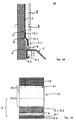
- a first embodiment of the invention is in Fig. 1A and 1B shown.
- a kit 20 for the production of wall closures between installation items such as a bathtub 2, or a shower tray or other sanitary or kitchen utensil and a closure wall. 1 for use.
- the kit 20 includes a separate from the installation item 2 elongated Zargenband 6 for attachment between the installation object 2 and the end wall 1.
- the frame strip 6 in the embodiment shown in the assembled state has an approximately T-shaped cross-section with an angled upper strip 6.1 (in the Fig.
- the roof area in the assembled state extends vertically and parallel to the end wall 1 and its legs (as the foot of the T's T-shaped cross section, which is perpendicular to the roof area) with a horizontal tub Abbordungs area 2.2 of the bathtub. 2 is glued.
- the frame strip 6 comprises a lower strip 6.2, which is more or less an extension of the roof area of the T and runs parallel to the end wall 1.
- the lower strip 6.2 of the Zargenbandes 6 has at least one sealingly attached to the installation object 2 surface.
- Fig. 1A is indicated by a dark gray strip 6.3 between the side facing away from the end wall 1 surface of the lower strip 6.2 and a parallel to the end wall 1 extending vertical surface 2.1 of the bathtub Abbordung that there is an adhesive.
- an adhesive surface is present on the underside of the leg of the upper angled strip 6.1, ie on the horizontal in the example shown underside, which rests on a horizontal surface 2.2 of the bathtub Abbordung.
- the Zargenband 6 further has a connected to the legs of the upper angled strip 6.1 back-feeding section 8, which runs parallel to the horizontal surface 2.2 of the bathtub Abbordung in the example shown.
- the kit 20 additionally comprises a separate from the installation item 2 elongated sealing tape 10 for attachment to the end wall 1.
- This sealing tape 10 has a water-impermeable overlap strip 10.2, the merges into a penetration strip 10.1.
- the overlap strip 10.2 and the penetration strip 10.1 are in the FIGS. 1A to 3 to recognize.
- the sealing tape 10 can be fixed to the end wall 1 after installation of the frame strip 6 (or another frame, such as a rigid frame) on the bath 2 and after placing the bathtub 2 against the end wall 1. Care is taken to ensure that the water-impermeable overlap strip 10.2 partially overlaps the roof area of the upper strip 6.1 of the T-shaped frame 6, as in FIG Fig. 1A and Fig. 1B indicated.
- the penetration strip 10.1 lies flat against the end wall 1 and is covered and impregnated with a coating liquid 13 in this particular embodiment.
- the area 21 of the penetration strip 10.1 is in Fig. 1A illustrates the penetration through a black and white dashed area.
- Fig. 1B shows area 21 as a diamond-shaped area.
- the sealing tape 10 on a back 11 which rests in the assembled state on the end wall 1, an adhesive surface 10.3 or an adhesive in order to fix the sealing tape 10 at least temporarily on the end wall 1 can.
- the entire handling is simplified, since the sealing tape 10 can be easily covered or rolled over after fixing with the coating liquid 13.
- the sealing tape 10 and / or the frame tape 6 may also be temporarily attached to the wall or floor with tape or other fasteners (such as screws, nails, rivets, glue, etc.) to bridge the time until then eg tiles are laid.
- tape or other fasteners such as screws, nails, rivets, glue, etc.
- the sealing tape 10 and / or the frame tape 6 may also be provided with means (e.g., sealing strips) to provide a tight connection to a wall or floor.
- means e.g., sealing strips
- the frame strip 6 may have an adhesive surface or adhesive on the upper strip 6.1 in order to be able to fix the sealing strip 10 at least temporarily to the frame strip 6.
- the kit additionally comprises the suitable brushable or rollable coating liquid 13, which is designed so that it penetrates after fixing the sealing strip 10 on the end wall 1 by sweeping or rolling over the fürdringungsstieifens 10.1 and a sealing connection to the end wall 1 or the floor generated.
- the coating liquid 13 is designed to protect the lightweight wall 1 or the floor from ingress of water.
- the coating liquid 13 fills the pores of the wall 1 or the floor and seals the wall 1 or the floor with a water-repellent protective layer.
- the coating liquid 13 used is a combination of a primer and a paintable liquid film.
- the overlap strip 10.2 is dimensioned so that it overlaps the upper strip 6.1 of the frame strip 6 from above in the assembled state, so that moisture, which runs down the end wall 1, over the fürdringungsstsammlung 10.1 and the overlap strip 10.2 from the end wall 1 away on a side facing away from the end wall 1 outside of the upper strip 6.1 passes.
- the back-feeding section 8 serves, on the one hand, for soundproofing between a wall covering plate 3 (for example a tile or a glass plate) and the rim 2.
- the back-feeding section 8 additionally serves as the basis for a sealing joint and as a spacer for the wall covering plates 3 during their laying.
- the back-feeding section 8 may have an extension which, as a protective strip, protects the tub rim 2 against contamination and damage during assembly. This extension of the back-feeding section 8 can be removed at a pre-perforated position after laying the wall covering plates 3.
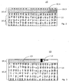
- FIGS. 2 and 3 are sub-steps of the production of a wall termination according to the invention can be seen, wherein Fig. 2 a first embodiment and Fig. 3 shows a second embodiment of the invention. Similarly, a conclusion can be made against a floor.
- the frame strip 6 is glued to the vertical bows 2.1.
- the back-feeding portion 8 is placed or glued with a part of the upper strip 6.1 on the horizontal tub edge 2.2.
- the adhesive bond of a part of the back-feeding section 8 should not be too tight here, if the front part of the back-feeding section 8 is to serve as a protective strip and should later be cut off at the aforementioned pre-perforated point.
- the sealing tape 10 is fixed to the end wall 1. This can be done by peeling off a protective film 10.4 on the rear side 11 of the sealing tape 10 in order to expose an adhesive strip 10.3.
- Fig. 2 are the later to be swept or penetrated fürdringungsstsammlung 10.1 and the overlap strip 10.2 indicated.
- the Penetration tabs 10.1 and overlap tabs 10.2 may both be made of the same material, with at least the overlap tab 10.2 being specifically impregnated to prevent passage of water.
- the penetration strip 10.1 is deliberately unimpregnated in a preferred embodiment, so that the coating liquid 13 reaches through the penetration strip 10.1 through the underlying wall 1 and connects to it.
- Particularly preferred is a penetration strip 10.1, which is porous, absorbent or even holey (for example, reticulated).
- Fig. 3 an embodiment is shown in which the penetration strip 10.1 is in the form of a porous gauze or other porous strip.
- the coating with the coating liquid 13 is in Fig. 3 indicated by a brush 12.
- the wall cover plates are attached.
- the optional front portion of the back-feeding section 8 can be torn off and pulled away.
- the back-feeding section 8 now serves as the basis for a sealing joint as a primary seal, for example of silicone material.
- FIG. 4 Another embodiment of the invention is in Fig. 4 shown. It comes from the installation item 2 separate, elongated Zargenband 6 is used, which is arranged between the installation object 2 and the end wall 1.
- the frame strip 6 In the mounted state, the frame strip 6 has the parallel to the end wall 1 extending lower strip 6.2, which has a sealingly attached to the installation object 2 to be flat.
- an adhesive strip or adhesive material can be used in Fig. 4 marked as dark gray strip 6.3.
- the frame tape 6 can be glued to the tub 2 and there is no water along the tub-Abbordungs-area 2.2 of the bathtub 2 run backwards between frame and wall 1.
- the elongate sealing strip 10 separate from the installation object 2 is used, which can be attached to the end wall 1, as shown schematically in FIG Fig. 4 indicated.
- This sealing tape 10 has the water-impermeable overlap strip 10.2, which merges into the upper area mentioned in the penetration strips 10.1.
- This penetration strip 10.1 is in the in Fig. 4 shown embodiment, which means that even the upper portion of the sealing tape 10 does not pass water.
- the fürdringungsstAIN 10.1 may be glued to the wall 1, screwed, welded, festgetackert or riveted.
- a back-feeding portion 8 is attached, which extends at right angles.
- This back-feeding section 8 can be glued to the horizontal region 2.2 of Abbordung the bathtub 2.
- the tiles 3 are then bonded to the wall 1 and the top of the sealing tape 10 with a conventional tile adhesive not shown in the figures.
- Fig. 4 It is shown that the bottom tile 3 gets up or sits on the back-feeding section 8. If you now tear off the back-feeding section 8 in the region of a perforation 8.1, then a piece of the back-feeding section 8 remains under the tile 3.
- the result is a kind of fillet, which can be filled with a joint material (eg silicone).
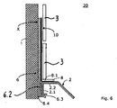
- Fig. 5 Another embodiment of the invention is in Fig. 5 shown. It comes from the installation item 2 separate, elongated Zargenband 6 is used, which is arranged between the installation object 2 and the end wall 1.
- This Zargenband 6 can be rigid or flexible.
- the frame strip 6 is glued in the area designated 6.3 against the installation object 2, where it ensures a watertight Connection.
- the designated 6.2 lower strip of the Zargenbandes 6 extends in height further upwards than in the other embodiments.
- the in Fig. 5 X is designated, the Zargenband 6 may have a fürdringungsstMail, which can be treated as in the sealing strip.
- the Zargenband 6 can also be fixed with the other means mentioned on the wall 1 or on a floor.
- the sealing strip 10 extends parallel to the frame strip 6. Either the frame strip 6 and the sealing strip 10 can be fastened together in the region X, or the sealing strip 10 is fastened, for example by adhering the tiles 3. As with the in Fig. 4 shown embodiment is also in the embodiment according to Fig. 5 the back-feeding section 8 is fastened to the sealing strip 10 and not to the frame strip 6.
- the frame band 6 and the sealing tape 10 are joined together, i.
- the two elements are not supplied individually, to be connected to each other only on site during installation.
- insulating strip 6.4 eg a foam strip
- This insulating strip 6.4 can be arranged on the outside (ie on the wall side) or on the inside (eg between the lower strip 6.2 and the strip 6.3).
- the installation kit 20 comprising at least the frame strip 6 and the sealing strip 10, allows a quick, trouble-free and reliable sealing of all possible sanitary and kitchen installations on an end wall.
- This invention is particularly suitable for use in dry construction in kitchens, bathrooms, swimming pools, but also in industrial environments where moisture may be present in Drywall or soils could penetrate.
- All parts can be pre-assembled or individually assembled and / or assembled on site.
Landscapes
- Health & Medical Sciences (AREA)
- Public Health (AREA)
- Epidemiology (AREA)
- General Health & Medical Sciences (AREA)
- Finishing Walls (AREA)
- Building Environments (AREA)
Description
Die Erfindung bezieht sich auf einen Einbausatz zur Herstellung von wasserdichten wand- und Bodenabschlüssen nach dem An- oder Einbau von Bade-, Duschwannen, Küchengeräten, Arbeitstischen usw., insbesondere auch an Leichtbauwänden und Trockenbauwänden, wie zum Beispiel an Holzfaser- und Gipskartonplatten, nach dem Oberbegriff des Anspruchs 1.The invention relates to a kit for the production of watertight wall and floor finishes after the installation or installation of baths, shower trays, kitchen appliances, work desks, etc., especially on lightweight walls and drywall, such as wood fiber and plasterboard after the preamble of
Es werden die Prioritäten der Schweizer Patentanmeldung
Bislang sind Bad- und Duschwannen mit festen, d.h. mit den Wannen in einem Stück gepressten, starren Zargen bekannt. Diese starr angebrachten Zargen haben den Nachteil, dass sie sich nicht an die entsprechenden Umstände des Einbauortes anpassen lassen. Je nach Einbausituation, z.B. mit oder ohne Mauernische, besteht ein Anpassüngsbedarf. Hierdurch bedingt, müssen Wannen mit festen Zargen daher im Werk entsprechend mit großem Aufwand speziell gefertigt werden. Da eine derartige Wanne mit durch Blechabkantung fest integrierter Zarge unveränderbar ist, kann Sie bei Fehldisposition nicht universell eingesetzt werden.So far, bath and shower trays with fixed, i. known with the tubs in one piece pressed, rigid frames. These rigidly mounted frames have the disadvantage that they can not be adapted to the corresponding circumstances of the installation site. Depending on the installation situation, e.g. with or without wall niche, there is a Anpassüngsbedarf. Due to this, tubs with fixed frames must therefore be specially manufactured in the factory with great effort. Since such a tray with fixed by Blechabkantung fixed frame is unchangeable, it can not be used universally in misallocation.
Gemäß dem Patent
Nun stellt sich aber immer häufiger das Problem, dass im Sanitär- und Küchenbereich Leichtbauwände, zum Beispiel aus Rigips oder Holz zum Einsatz kommen. Diese Wände sind sehr empfindlich gegen Feuchtigkeit und es musste bisher ein großer Aufwand betrieben werden, um solche Wände vor eindringendem Wasser zu schützen. Es bleibt aber das Risiko von Wasserinfiltration und den entsprechenden Folgeschäden außerhalb des Sicherheitsbereichs von Flexzargen, d.h. durch die Hinterwanderung von Wasser zwischen der an Wänden bzw. Böden lose anliegenden Flexzargenborde und der Rohwand.Now, however, the problem increasingly arises that in the sanitary and kitchen area lightweight walls, for example made of plasterboard or wood are used. These walls are very sensitive to moisture and so far a great deal of effort has been made to protect such walls from ingress of water. However, there remains the risk of water infiltration and the consequential damage outside the safety margin of flex frames, i. by the migration of water between the loosely fitting Flexzargenborde walls and floors and the Rohwand.
Bisher gibt es keine Lösung, die es zu verhindern ermöglicht, dass Wasser, das zum Beispiel durch brüchige Kitt- oder Mörtelfugen hindurch hinter Fliesen oder andere Verkleidungsplatten gelangt, in die Wand eindringt. Selbst durch oberflächenbehandelte Wände wird das Problem nicht gelöst, da zwar das Wasser nicht unmittelbar in die Wand eindringen kann, aber an der Wand abwärts rinnt und dann am Übergang zum Boden Schäden verursachen kann.So far, there is no solution that prevents it, that penetrates, for example, through brittle putty or mortar joints behind tiles or other cladding panels, penetrates into the wall. Even with surface-treated walls, the problem is not solved, because although the water can not penetrate directly into the wall, but runs down the wall and then cause damage at the transition to the ground.
Die Erfindung hat die Aufgabe, einen Einbausatz zur Herstellung von wasserdichten Wandanschlüssen und/oder Bodenabschlüssen für Einbaugegenstände (Badewannen, Duschwannen, Arbeitsplatten in Küchen, und dergleichen) vorzuschlagen, wobei eine problemlose und einfache Anpassung an die am Einbauort vorliegenden besonderen Gegebenheiten vor Ort möglich ist.The invention has the object to provide a kit for the production of watertight wall connections and / or bottom finishes for installation items (bathtubs, shower trays, kitchen countertops, and the like), with a simple and easy adaptation to the present on site installation conditions is possible on site ,
Diese Aufgabe wird, ausgehend von einem bekannten flexiblen Zargenband der einleitend genannten Art, durch die kennzeichnenden Merkmale des Anspruchs 1 gelöst.This object is achieved on the basis of a known flexible Zargenband the introductory type, by the characterizing features of
Durch die in den Unteransprüchen genannten Maßnahmen sind vorteilhafte Ausführungen und Weiterbildungen angegeben.The measures mentioned in the dependent claims advantageous embodiments and developments are given.
Dementsprechend wird zusätzlich zu einem z.B. T-förmigen, flexiblen Zargenband ein vom Einbaugegenstand separates Dichtband zum Anbringen an der Abschlusswand vorgesehen. Dieses Dichtband wird hierbei so ausgeführt, dass es in eingebautem Zustand mit einem wasserundurchlässigen Uberlappungsstreifen einen oberen Streifen des Zargenbandes überlappt. Außerdem umfasst das Dichtband in dieser speziellen Ausführungsform einen sogenannten Durchdringungsstreifen, der durch Überstreichen oder Überrollen mit einer Beschichtungsflüssigkeit dicht mit der darunter liegenden Abschlusswand verbunden wird.Accordingly, in addition to e.g. T-shaped, flexible Zargenband a separate from the installation item sealing tape provided for attachment to the end wall. This sealing tape is here designed so that it overlaps in the installed state with a water-impermeable overlap strip an upper strip of the Zargenbandes. In addition, in this particular embodiment, the sealing tape comprises a so-called penetration strip, which is connected by coating or rolling over with a coating liquid close to the underlying end wall.
Die Zarge kann vor Ort jeweils an den Seiten des Einbaugegenstandes angebracht werden, die an einer Abschlusswand oder einem Boden zu liegen kommen und somit einen Abschluss benötigen. Dann wird der Einbaugegenstand an die Abschlusswand oder auf den Boden gestellt und es wird das Dichtband an der Abschlusswand oder am Boden so fixiert, dass der wasserundurchlässige Überlappungsstreifen den oberen Streifen des Zargenbandes überlappt.The frame can be mounted on site on the sides of the installation object, which come to rest on an end wall or floor and thus require a degree. Then the fixture is placed on the end wall or floor and the sealing tape is fixed to the end wall or floor so that the waterproof overlap strip overlaps the top strip of the frame tape.
Anschließend wird der Durchdringungsstreifen und der darüber liegende Bereich der Abschlusswand oder des Bodens mit der Beschichtungsflüssigkeit überstrichen oder überrollt.Subsequently, the penetration strip and the overlying area of the end wall or the floor is coated or rolled over with the coating liquid.
Sind die Einbaugegenstände beispielsweise eine Bade- oder Duschwanne, so kann z.B. mit der T-förmigen, flexiblen Zarge zusammen mit dem Dichtband mit wenigen Handgriffen ein sauberer und dichter wandabschluss oder Bodenabschluss erstellt werden. Statt der T-förmigen, flexiblen Zarge können aber auch einfacher ausgeformte Zargen zum Einsatz kommen. Es können aber auch starre Zargen (z.B. aus Blech oder Metallfolie) im Zusammenhang mit der Erfindung eingesetzt werden.If the installation items, for example, a bath or shower tray, so for example with the T-shaped, flexible frame together with the sealing tape with a few simple steps a clean and dense wall or bottom closure are created. But instead of the T-shaped, flexible frame but also simpler frames can be used. But it can also rigid frames (eg sheet metal or metal foil) in Used in connection with the invention.
Die in Leichtbauweise erstellte Abschlusswand oder ein entsprechender Bodenbereich ist somit zuverlässig vor Feuchtigkeit geschützt.The lightweight wall or a corresponding floor area is thus reliably protected from moisture.
Vorteilhafterweise wird das Dichtband wenigstens teilweise aus flexiblem Material gefertigt. Hierdurch kann das Dichtband Wannenbewegungen, z.B. durch Bodensenkung aufgrund von Schwund oder Verwerfung der Estriche bzw. Unterlagsböden nachgeben, ohne dass die den Wandbelag bildenden Keramikplatten (Fliesen) beschädigt werden. Auch die Dichtheit wird beim Nachgeben eines derart elastischen Materials nicht beeinträchtigt.Advantageously, the sealing tape is at least partially made of flexible material. This allows the sealing band to move the tub, e.g. due to subsidence due to shrinkage or warping of the screeds or underlay floors give, without the ceramic tiles forming the wall covering (tiles) are damaged. The tightness is not affected when yielding such an elastic material.
Je nach Bedarf kann ein erfindungsgemäßes Dichtband zumindest teilweise aus Kunststoff, aus textilen Werkstoffen und/oder Metallfolien und/oder Blech gefertigt werden. Die Materialauswahl für ein derartiges Dichtband hängt vom jeweiligen Einsatzgebiet ab und kann dementsprechend angepasst werden. Das Dichtband kann vorzugsweise vor Ort zugeschnitten und somit in jeder Situation angepasst werden. Das Dichtbands samt Zargenband (z.B. ein T-förmiges flexibles oder starres Zargenband) kann aber auch als Fertigbausatz (vorkonfektioniert) geliefert werden.Depending on requirements, a sealing tape according to the invention can be made at least partially of plastic, of textile materials and / or metal foils and / or sheet metal. The choice of material for such a sealing tape depends on the particular application and can be adjusted accordingly. The sealing tape can preferably be cut on site and thus adapted in every situation. The sealing tape together with Zargenband (for example, a T-shaped flexible or rigid Zargenband) but can also be supplied as a prefabricated kit (prefabricated).
Für die Fixierung des Dichtbandes an der Abschlusswand oder am Boden sind Verklebungen bevorzugt. Es muss darauf geachtet werden, dass das Dichtband möglichst flächig an der entsprechenden Fläche der Abschlusswand oder des Bodens anliegt. Statt des Verklebens kann das Dichtband aber auch geschraubt, genietet, verschweißt, aufvulkanisiert, getackert oder mit einem Klebestreifen oder mit Flüssigkunststoff fixiert werden.For the fixation of the sealing tape on the end wall or on the floor gluing is preferred. Care must be taken that the sealing tape lies as flat as possible against the corresponding surface of the end wall or the floor. Instead of gluing the sealing tape but can also be screwed, riveted, welded, vulcanized, stapled or fixed with an adhesive strip or with liquid plastic.
Im Fall einer klebenden Fixierung des Dichtbandes ist die Verwendung eines Selbstklebebandes zu empfehlen. Auf diese Weise ist das Dichtband besonders leicht zu handhaben. Es kann am Einbauort durch festes Andrücken an die Abschlusswand oder an den Boden befestigt werden. Denkbar sind jedoch auch andere Klebemöglichkeiten, beispielsweise mittels einer Klebemasse, d.h. mit einer Masse, die auf eine Rückseite des Dichtbandes oder direkt auf die Abschlusswand oder den Boden aufgetragen wird.In the case of an adhesive fixation of the sealing tape, the use of a self-adhesive tape is recommended. In this way, the sealing tape is particularly easy to handle. It can be fixed to the installation site by pressing firmly on the end wall or on the floor. However, it is also conceivable other adhesive options, for example by means of an adhesive, i. with a mass applied to a back of the sealing tape or directly to the end wall or floor.
Diese Fixierung dient hauptsächlich dazu, das Dichtband an der Abschlusswand zu fixieren, bis es durch die aufzutragende Beschichtungsflüssigkeit dicht mit der darunter liegenden Abschlusswand verbunden ist. Anstatt eine solche Beschichtungsflüssigkeit nachträglich aufzutragen, kann das Dichtband oder mindestens ein oberer Bereich des Dichtbands auch bereits ab Werk so ausgeführt sein, dass es in sich dicht ist.This fixation is mainly used to fix the sealing tape to the end wall, until it is connected by the coating liquid to be applied tightly with the underlying end wall. Instead of subsequently applying such a coating liquid, the sealing tape or at least one upper region of the sealing tape can already be made ex works so that it is tight in itself.
In einer weiteren Ausführungsform umfasst das Zargenband einen Durchdringungsstreifen.In a further embodiment, the frame strap comprises a penetration strip.
Das Zargenband kann auch einen oder zwei Streifen, z.B. aus dickem, weichem Material (vorzugsweise Schaumstoff), aufweisen, um für eine Schallentkopplung zwischen einer Badewanne oder einer Dusche und der Wand oder dem Boden zu sorgen.The frame strap may also have one or two strips, e.g. of thick, soft material (preferably foam) to provide sound isolation between a bathtub or a shower and the wall or floor.
Weitere Vorteile ergeben sich unmittelbar aus der Beschreibung und den dazu gehörenden Zeichnungen.Further advantages emerge directly from the description and the accompanying drawings.
Im Folgenden wird die Erfindung anhand von Ausführungabeispielen und mit Bezug auf die Zeichnungen ausführlich beschrieben. Es zeigen:
-
Fig. 1A eine erste Anwendungssituation in einer schematischen, seitlichen Schnittdarstellung, in der ein erfindungsgemäßes Einbausystem beim Einbau einer Badewanne zum Einsatz kommt; -
Fig. 1B die erste Anwendungssituation in einer schematischen Vorderansicht; -
Fig. 2 ein erstes Ausführungsbeispiel des erfindungsgemäßen Dichtbandes; -
Fig. 3 ein zweites Ausführungsbeispiel des erfindungsgemäßen Dichtbandes; -
Fig. 4 eine weitere Anwendungssituation in einer schematischen, seitlichen Schnittdarstellung, in der ein weiteres erfindungsgemäßes Einbausystem beim Einbau einer Badewanne zum Einsatz kommt; -
Fig. 5 eine weitere Anwendungssituation in einer schematischen, seitlichen Schnittdarstellung, in der noch ein weiteres erfindungsgemäßes Einbausystem beim Einbau einer Badewanne zum Einsatz kommt; -
Fig. 6 eine weitere Anwendungssituation in einer schematischen, seitlichen Schnittdarstellung, in der noch ein weiteres erfindungsgemäßes Einbausystem beim Einbau einer Badewanne zum Einsatz kommt.
-
Fig. 1A a first application situation in a schematic, lateral sectional view, in which an inventive Built-in system is used when installing a bathtub; -
Fig. 1B the first application situation in a schematic front view; -
Fig. 2 a first embodiment of the sealing strip according to the invention; -
Fig. 3 A second embodiment of the sealing strip according to the invention; -
Fig. 4 a further application situation in a schematic, lateral sectional view, in which a further installation system according to the invention is used when installing a bathtub; -
Fig. 5 a further application situation in a schematic, side sectional view, in which still another inventive installation system when installing a bathtub is used; -
Fig. 6 a further application situation in a schematic, lateral sectional view, in which still another inventive installation system when installing a bathtub is used.
Gleiche, bzw. gleich wirkende konstruktive Elemente sind in den Figuren mit gleichen Bezugszeichen versehen, auch wenn sie sich teilweise voneinander unterscheiden. Angaben wie oben, unten, rechts, links, vorne, hinten beziehen sich auf die Lage der so bezeichneten Elemente in den jeweiligen Figuren.The same or equivalent structural elements are provided in the figures with the same reference numerals, even if they differ from each other in part. Information such as above, below, right, left, front, back refer to the location of the so-called elements in the respective figures.
Die verschiedenen Schichten und Komponenten sind in den Figuren nicht maßstäblich gezeichnet. Einzelne Schichten sind besonders dick hervorgehoben, um ihre Position und Anordnung zeigen zu können.The various layers and components are not drawn to scale in the figures. Individual layers are emphasized to show their position and arrangement.
Eine erste Ausführungsform der Erfindung ist in
Der untere Streifen 6.2 des Zargenbandes 6 hat mindestens eine dichtend an dem Einbaugegenstand 2 zu befestigende Fläche. In
Gemäß Erfindung umfasst der Einbausatz 20 zusätzlich ein vom Einbaugegenstand 2 separates längliches Dichtband 10 zum Anbringen an der Abschlusswand 1. Dieses Dichtband 10 weist einen wasserundurchlässigen Überlappungsstreifen 10.2 auf, der in einen Durchdringungsstreifen 10.1 übergeht. Der Überlappungsstreifen 10.2 und der Durchdringungsstreifen 10.1 sind in den
Wie in
In einer bevorzugten Ausführungsform weist das Dichtband 10 auf einer Rückseite 11 (
Das Dichtband 10 und/oder das Zargenband 6 kann/können auch temporär mit einem Klebeband oder mit anderen Befestigungsmitteln (wie Schrauben, Nägel, Nieten, Klebstoff, usw.) an der Wand oder dem Boden befestigt werden, um die Zeit zu überbrücken, bis dann z.B. Fliesen verlegt werden.The sealing
Das Dichtband 10 und/oder das Zargenband 6 kann/können auch mit Mitteln (z.B. Dichtstreifen) versehen sein, um für eine dichte Verbindung mit einer Wand oder einem Boden zu sorgen.The sealing
Bei einer anderen Ausführungsform (nicht gezeigt), weist das Dichtband 10 auf der Rückseite 11, die im montierten Zustand an dem oberen Streifen 6.1 des Zargenbandes 6 anliegt, eine Klebefläche oder ein Klebemittel auf. Zusätzlich oder alternativ kann das Zargenband 6 an dem oberen Streifen 6.1 eine Klebefläche oder ein Klebemittel aufweisen, um das Dichtband 10 mindestens temporär an dem Zargenband 6 fixieren zu können.In another embodiment (not shown), the sealing
Gemäß einer weiteren Ausführungsform der Erfindung umfasst der Einbausatz zusätzlich die geeignete streich- oder rollbare Beschichtungsflüssigkeit 13, die so ausgelegt ist, dass sie nach dem Fixieren des Dichtbandes 10 an der Abschlusswand 1 durch Überstreichen oder Überrollen des Durchdringungsstieifens 10.1 diesen durchdringt und eine dichtende Verbindung zu der Abschlusswand 1 oder dem Boden erzeugt. Außerdem ist die Beschichtungsflüssigkeit 13 so ausgelegt, dass sie die Leichtbauwand 1 oder den Boden gegen das Eindringen von Wasser schützt. Vorzugsweise füllt die Beschichtungsflüssigkeit 13 die Poren der Wand 1 oder des Bodens und versiegelt die Wand 1 oder den Boden mit einer wasserabweisenden Schutzschicht.According to a further embodiment of the invention, the kit additionally comprises the suitable brushable or
Vorzugsweise kommt als Beschichtungsflüssigkeit 13 eine Kombination aus einem Voranstrich und einer aufstreichbaren Flüssigfolie zum Einsatz.Preferably, the
Besonders bevorzugt ist eine Ausführungsform, bei der der Uberlappungsstreifen 10.2 so dimensioniert ist, dass er im montierten Zustand den oberen Streifen 6.1 des Zargenbandes 6 von oben her überlappt, damit Feuchtigkeit, die an der Abschlusswand 1 abwärts rinnt, über den Durchdringungsstreifen 10.1 und den Überlappungsstreifen 10.2 von der Abschlusswand 1 weg auf eine von der Abschlusswand 1 abgewandte Außenseite des oberen Streifens 6.1 gelangt.Particularly preferred is an embodiment in which the overlap strip 10.2 is dimensioned so that it overlaps the upper strip 6.1 of the
Der Hinterfütterungsabschnitt 8 dient zum einen zur Schallisolierung zwischen einer Wandbelagplatte 3 (zum Beispiel einer Fliese oder einer Glasplatte) und dem Wannenrand 2. Der Hinterfütterungsabschnitt 8 dient zusätzlich als Basis für eine Dichtfuge sowie als Abstandshalter für die Wandbelagplatten 3 bei deren Verlegung. Der Hinterfütterungsabschnitt 8 kann eine Verlängerung aufweisen, die als Schutzstreifen den Wannenrand 2 vor Verunreinigung und Beschädigung während der Montage schützt. Diese Verlängerung des Hinterfütterungsabschnitts 8 kann an einer vorperforierten Stelle nach dem Verlegen der Wandbelagplatten 3 entfernt werden.The back-
Aus den
Zunächst wird das Zargenband 6 am Vertikalabbug 2.1 angeklebt. Sodann wird der Hinterfütterungsabschnitt 8 mit einem Teil des oberen Streifens 6.1 auf den horizontalen Wannenrand 2.2 gelegt oder geklebt. Die Klebeverbindung eines Teils des Hinterfütterungsabschnitts 8 sollte hier nicht allzu fest sitzen, falls der vordere Teil des Hinterfütterungsabschnitts 8 als Schutzstreifen dienen soll und später an der erwähnten vorperforierten Stelle abgetrennt werden soll.First, the
Nun wird das Dichtband 10 an der Abschlusswand 1 fixiert. Das kann dadurch geschehen, dass man auf der Rückseite 11 des Dichtbandes 10 eine Schutzfolie 10.4 abzieht, um einen Klebestreifen 10.3 freizulegen. In
In
Eine weitere Ausführungsform der Erfindung ist in
Am unteren Ende des Dichtbands 10 ist ein Hinterfütterungsabschnitt 8 angebracht, der rechtwinklig verläuft. Dieser Hinterfütterungsabschnitt 8 kann auf den horizontalen Bereich 2.2 der Abbordung der Badewanne 2 aufgeklebt werden. Die Fliesen 3 werden dann mit einem üblichen Fliesenkleber, der nicht in den Figuren gezeigt ist, auf die Wand 1 und den oberen Bereich des Dichtbands 10 geklebt.At the lower end of the sealing
In
Eine weitere Ausführungsform der Erfindung ist in
In einer weiteren Ausführungsform sind das Zargenband 6 und das Dichtband 10 miteinander verbunden, d.h. die beiden Elemente werden nicht einzeln geliefert, um erst vor Ort beim Einbau miteinander verbunden zu werden.In a further embodiment, the
In
Der erfindungsgemäße Einbausatz 20, mindestens das Zargenband 6 und das Dichtband 10 umfassend, ermöglicht eine schnelle, problemlose und zuverlässige Abdichtung aller möglichen Sanitär- und Kücheninstallationen an einer Abschlusswand. Besonders geeignet ist diese Erfindung zur Verwendung im Trockenbau in Küchen, Bädern, Schwimmbädern, aber auch im industriellen Umfeld, wo eventuell Feuchtigkeit in Trockenbauwände oder Böden eindringen könnte.The
Erst die Kombination aus einer flexiblen Zarge 6 und dem beschriebenen Dichtband 10, zusammen mit einer geeigneten Beschichtungsflüssigkeit 13, führt zu einer zufriedenstellenden und problemlosen Abdichtung. Statt der Beschichtungsflüssigkeit 13 können aber auch andere Befestigungsmittel, wie beschrieben zum Einsatz kommen.Only the combination of a
Sämtliche Teile können vorkonfektioniert oder einzeln am Bau zusammengestellt und/oder montiert werden.All parts can be pre-assembled or individually assembled and / or assembled on site.
Claims (12)
- Installation kit (20) for producing wall terminations between installed articles (2) and a termination wall (1) or a floor;
the installation kit (20) comprising, separate from the installed article (2), an oblong frame tape (6) for being placed between installed article (2) and termination wall (1) or floor;
the frame tape (6) having in the mounted state a first strip (6.2), parallel to the termination wall (1) or the floor;
the first strip (6.2) having a surface to be fastened sealed on the installed article (2);
and the frame tape (6) having a second strip-shaped area (6.1), extending in the mounted state parallel to the termination wall (1) or to the floor as prolongation of the first strip (6.2);- the installation kit (20) comprising additionally an oblong sealing tape (10), separate from the installed article (2) and for being placed to the termination wall (1) or the floor;- this sealing tape (10) having a water-impermeable overlapping strip (10.2), which, in the mounted state of the installation kit (20) overlaps the second strip-shaped area (6.1) to the side of the installed article (2) and- that the overlapping strip (10.2) passes into a mounting strip (10.1) for mounting onto the termination wall (1),characterized in that- the installation kit (20) comprises a backing portion (8), which in the mounted state, is affixable on a deflection edge (2.2) of the installed article (2). - Installation kit (20) according to claim 1, characterized in that the frame tape (6) has an upper strip (6.1), serving as second strip-shaped area, and a first strip (6.2), extending parallel to the termination wall (1) as a lower strip, where the upper strip (6.1) and the lower strip (6.2) have surfaces to be mounted sealed on the installed article (2), and the backing portion (8) is part of the frame tape (6).
- Installation kit (20) according to claim 1, characterized in that the backing portion (8) is part of the sealing tape (10).
- Installation kit (20) according to claim 1, 2 or 3,
characterized in that the mounting strip (10.1) of the sealing tape (10) is designed as permeable strip (10.1). - Installation kit (20) according to claim 4, characterized in that the sealing tape (10) has, on a rear side (11) which abuts in the mounted state on the termination wall (1), an adhesive surface (10.3) or an adhesive, with which the sealing tape (10) is at least temporarily fixable on the termination wall (1).
- Installation kit (20) according to claim 4, characterized in that- the sealing tape (10) has, on a rear side (11) which abuts in the mounted state on the upper strip (6.1) of the frame tape (6), an adhesive surface or an adhesive,and/or- the frame tape (6) has, at the upper strip (6.1) an adhesive surface or an adhesive, with which the sealing tape (10) is fixable at least temporarily or permanently sealed on the frame tape (6).
- Installation kit (20) according to claim 4 or 5,
characterized in that the installation kit (20) additionally comprises a spreadable or rollable coating liquid (13) which is designed so that after fixing the sealing tape (10) on the termination wall (1) it can be painted or rolled over in the area of the water-permeable strip (10.1), so that the coating liquid (13) penetrates through the permeable strip (10.1) and creates a sealing connection to the termination wall (1). - Installation kit (20) according to one of the preceding claims, characterized in that the overlapping strip (10.2) is dimensioned such that it overlaps in mounted state the upper strip (6.1) from above, so that moisture trickling down on the termination wall (1) and running over the permeable strip (10.1) and the overlapping strip (10.2) gets away from the termination wall (1) onto an outer side of the frame tape (6), this outer side being far side to the termination wall (1).
- Installation kit (20) according to one of the preceding claims, characterized in that the sealing tape (10) is at least partially made of a flexible material.
- Installation kit (20) according to one of the preceding claims, characterized in that the sealing tape (10) is made at least partially of plastic, of textile material and/or metal foil and/or of metal sheet.
- Installation kit (20) according to one of the preceding claims, characterized in that the sealing tape (10) and/or the frame tape (6) comprises an insulation strip (6.4) for sound insulation.
- Bath tub or shower tub (2), characterized in that it is mounted onto a termination wall (1) or a floor with a frame tape (6) and a sealing strip (10), according to one of the preceding claims.
Applications Claiming Priority (3)
| Application Number | Priority Date | Filing Date | Title |
|---|---|---|---|
| CH01916/06A CH715223B1 (en) | 2006-11-28 | 2006-11-28 | Installation kit for the production of wall closures between built-in objects and an end wall. |
| DE202007003943U DE202007003943U1 (en) | 2006-11-28 | 2007-03-17 | Insert for producing water-tight wall/floor seals after installation of baths, shower trays or kitchen appliances comprises a frame strip and a sealing strip that has a water-impermeable overlap strip that changes into a permeable strip |
| PCT/EP2007/062846 WO2008065096A1 (en) | 2006-11-28 | 2007-11-27 | Installation kit for producing wall or floor terminations between installed articles and a termination wall or a floor |
Publications (2)
| Publication Number | Publication Date |
|---|---|
| EP2129272A1 EP2129272A1 (en) | 2009-12-09 |
| EP2129272B1 true EP2129272B1 (en) | 2016-03-09 |
Family
ID=38109402
Family Applications (1)
| Application Number | Title | Priority Date | Filing Date |
|---|---|---|---|
| EP07847373.3A Active EP2129272B1 (en) | 2006-11-28 | 2007-11-27 | Installation kit for producing wall or floor terminations between installed articles and a termination wall or a floor |
Country Status (4)
| Country | Link |
|---|---|
| EP (1) | EP2129272B1 (en) |
| CH (1) | CH715223B1 (en) |
| DE (1) | DE202007003943U1 (en) |
| WO (1) | WO2008065096A1 (en) |
Families Citing this family (10)
| Publication number | Priority date | Publication date | Assignee | Title |
|---|---|---|---|---|
| ATE482317T1 (en) | 2007-12-07 | 2010-10-15 | Geberit Int Ag | METHOD FOR INSTALLING A DRAIN IN A SUBSTRATE FLOOR, DRAIN WITH A DRAIN TRAY AND BUILDING FLOOR WITH SUCH A DRAIN |
| DE102008057851A1 (en) * | 2008-11-18 | 2010-06-10 | Bernd Urban und Anna Urban GbR (vertretungsberechtigte Gesellschafter: Anna Urban, 42279 Wuppertal, Bernd Urban, 42279 Wuppertal) | Sealing element for use with assembly roiling box, for forming wall connection at sanitary items, particularly bath tubs, is formed by base body in form of metal foil, where sanitary-item is provided with two adhesive areas |
| GB2468116A (en) * | 2009-01-26 | 2010-09-01 | Michael Herbert Charles Smith | Sanitary-ware sealing system |
| AT510126B1 (en) * | 2010-03-18 | 2016-01-15 | Urs Gassmann | ECKAUSGLEICHS PROFILE |
| AT510127B1 (en) * | 2010-03-18 | 2016-01-15 | Urs Gassmann | SEAL AND ASSEMBLY BELT WITH A CUT PROTECTION |
| DE102011101821A1 (en) | 2010-07-09 | 2012-03-08 | Urs Gassmann | Corner input profile for rounded corner of mounting object on e.g. wall, has |
| CH707133B1 (en) * | 2012-10-29 | 2017-05-15 | Sanipat Gmbh | Sealing tape set for bath or shower tray. |
| GB2518649B (en) * | 2013-09-27 | 2015-09-02 | Gerard Francis Robinson | Sealing member |
| ES1103858Y (en) * | 2014-02-28 | 2014-06-10 | Estil Guru S L | MULTIAXIAL SEALING BAND |
| AT17427U1 (en) * | 2020-09-23 | 2022-03-15 | Edm System Gmbh | Sealing and assembly device for sanitary facilities |
Family Cites Families (4)
| Publication number | Priority date | Publication date | Assignee | Title |
|---|---|---|---|---|
| DE3318116A1 (en) * | 1983-05-18 | 1984-11-22 | Engelhard 7500 Karlsruhe Unger | Sealing profile for sanitary articles of daily use, in particular for shower trays and bathtubs |
| DE9006767U1 (en) * | 1990-06-16 | 1990-12-13 | Schilling, Siegfried, 7890 Waldshut-Tiengen | Plastic angle profile strip and its application for sealing wall connections |
| CH690162A5 (en) * | 1995-01-08 | 2000-05-31 | Alfred Gassmann | Frame for producing wall edges |
| GB2387626B (en) * | 2002-04-18 | 2005-09-21 | Polypipe Building Products Ltd | Sealing member |
-
2006
- 2006-11-28 CH CH01916/06A patent/CH715223B1/en not_active IP Right Cessation
-
2007
- 2007-03-17 DE DE202007003943U patent/DE202007003943U1/en not_active Expired - Lifetime
- 2007-11-27 EP EP07847373.3A patent/EP2129272B1/en active Active
- 2007-11-27 WO PCT/EP2007/062846 patent/WO2008065096A1/en active Application Filing
Also Published As
| Publication number | Publication date |
|---|---|
| CH715223B1 (en) | 2020-01-31 |
| WO2008065096A1 (en) | 2008-06-05 |
| EP2129272A1 (en) | 2009-12-09 |
| DE202007003943U1 (en) | 2007-05-24 |
Similar Documents
| Publication | Publication Date | Title |
|---|---|---|
| EP2129272B1 (en) | Installation kit for producing wall or floor terminations between installed articles and a termination wall or a floor | |
| EP1967107B1 (en) | Connecting Joint for Sanitary Devices | |
| EP3548677B1 (en) | Method for renovating and reconstructing wet rooms | |
| EP1038485A2 (en) | Sealing arrangement for sealing the edge area of a sanitary tub to the wall or the floor of a room | |
| EP0748179B1 (en) | Frame for making wall edges | |
| EP2425755B1 (en) | Shower tray | |
| DE102006026708B4 (en) | shower enclosure | |
| AT518596B1 (en) | Device with cut protection strips and corresponding cut protection strips | |
| DE202008014589U1 (en) | Plate-like component | |
| CH705742B1 (en) | Mounting kit for achieving a sealing effect and appropriately equipped plumbing. | |
| DE202010010410U1 (en) | Fugenabdichtband | |
| CH690162A5 (en) | Frame for producing wall edges | |
| DE102012105555B4 (en) | Receiving unit for receiving a weighing unit and arrangement for determining a mass | |
| DE19723153A1 (en) | Shower tray | |
| DE102019101502A1 (en) | Device for sealing between wall and floor surfaces of buildings | |
| AT518597B1 (en) | Connecting band, which serves as a transition between a device and a vertical surface, and methods for creating such a transition | |
| EP3031371B1 (en) | Floor level shower surface unit which is ready for installation | |
| DE202014103287U1 (en) | Wall covering for a hygiene area | |
| EP0723757A1 (en) | Supporting system for bath tubs or shower tubs | |
| DE202009002391U1 (en) | Sealing tape for edge finishing profiles | |
| CH713621B1 (en) | Device for creating a transition between a sanitary facility and a vertical surface and a method for creating such a transition and a damp or wet area with such a transition. | |
| DE10119716A1 (en) | Installation of a bath tub, against a tiled wall, has a seal of a rubber/polymer mass between the bath edge and the wall, covered by a bonded shrouding | |
| DE29502428U1 (en) | Frame for the production of wall closures | |
| DE202016006579U1 (en) | Large-area component | |
| AT13997U1 (en) | Mounting aid and mounting kit with such an assembly aid for creating a wall connection |
Legal Events
| Date | Code | Title | Description |
|---|---|---|---|
| PUAI | Public reference made under article 153(3) epc to a published international application that has entered the european phase |
Free format text: ORIGINAL CODE: 0009012 |
|
| 17P | Request for examination filed |
Effective date: 20090628 |
|
| AK | Designated contracting states |
Kind code of ref document: A1 Designated state(s): AT BE BG CH CY CZ DE DK EE ES FI FR GB GR HU IE IS IT LI LT LU LV MC MT NL PL PT RO SE SI SK TR |
|
| DAX | Request for extension of the european patent (deleted) | ||
| 17Q | First examination report despatched |
Effective date: 20101027 |
|
| GRAP | Despatch of communication of intention to grant a patent |
Free format text: ORIGINAL CODE: EPIDOSNIGR1 |
|
| INTG | Intention to grant announced |
Effective date: 20150625 |
|
| GRAS | Grant fee paid |
Free format text: ORIGINAL CODE: EPIDOSNIGR3 |
|
| GRAA | (expected) grant |
Free format text: ORIGINAL CODE: 0009210 |
|
| RIN1 | Information on inventor provided before grant (corrected) |
Inventor name: GASSMANN, ALFRED |
|
| AK | Designated contracting states |
Kind code of ref document: B1 Designated state(s): AT BE BG CH CY CZ DE DK EE ES FI FR GB GR HU IE IS IT LI LT LU LV MC MT NL PL PT RO SE SI SK TR |
|
| REG | Reference to a national code |
Ref country code: GB Ref legal event code: FG4D Free format text: NOT ENGLISH |
|
| REG | Reference to a national code |
Ref country code: AT Ref legal event code: REF Ref document number: 778837 Country of ref document: AT Kind code of ref document: T Effective date: 20160315 Ref country code: CH Ref legal event code: EP |
|
| REG | Reference to a national code |
Ref country code: IE Ref legal event code: FG4D Free format text: LANGUAGE OF EP DOCUMENT: GERMAN |
|
| REG | Reference to a national code |
Ref country code: DE Ref legal event code: R096 Ref document number: 502007014613 Country of ref document: DE |
|
| REG | Reference to a national code |
Ref country code: CH Ref legal event code: NV Representative=s name: PATENT- AND MARKENBUERO REB, CH |
|
| REG | Reference to a national code |
Ref country code: LT Ref legal event code: MG4D |
|
| REG | Reference to a national code |
Ref country code: NL Ref legal event code: MP Effective date: 20160309 |
|
| PG25 | Lapsed in a contracting state [announced via postgrant information from national office to epo] |
Ref country code: ES Free format text: LAPSE BECAUSE OF FAILURE TO SUBMIT A TRANSLATION OF THE DESCRIPTION OR TO PAY THE FEE WITHIN THE PRESCRIBED TIME-LIMIT Effective date: 20160309 Ref country code: GR Free format text: LAPSE BECAUSE OF FAILURE TO SUBMIT A TRANSLATION OF THE DESCRIPTION OR TO PAY THE FEE WITHIN THE PRESCRIBED TIME-LIMIT Effective date: 20160610 Ref country code: FI Free format text: LAPSE BECAUSE OF FAILURE TO SUBMIT A TRANSLATION OF THE DESCRIPTION OR TO PAY THE FEE WITHIN THE PRESCRIBED TIME-LIMIT Effective date: 20160309 |
|
| PG25 | Lapsed in a contracting state [announced via postgrant information from national office to epo] |
Ref country code: PL Free format text: LAPSE BECAUSE OF FAILURE TO SUBMIT A TRANSLATION OF THE DESCRIPTION OR TO PAY THE FEE WITHIN THE PRESCRIBED TIME-LIMIT Effective date: 20160309 Ref country code: NL Free format text: LAPSE BECAUSE OF FAILURE TO SUBMIT A TRANSLATION OF THE DESCRIPTION OR TO PAY THE FEE WITHIN THE PRESCRIBED TIME-LIMIT Effective date: 20160309 Ref country code: SE Free format text: LAPSE BECAUSE OF FAILURE TO SUBMIT A TRANSLATION OF THE DESCRIPTION OR TO PAY THE FEE WITHIN THE PRESCRIBED TIME-LIMIT Effective date: 20160309 Ref country code: LV Free format text: LAPSE BECAUSE OF FAILURE TO SUBMIT A TRANSLATION OF THE DESCRIPTION OR TO PAY THE FEE WITHIN THE PRESCRIBED TIME-LIMIT Effective date: 20160309 Ref country code: LT Free format text: LAPSE BECAUSE OF FAILURE TO SUBMIT A TRANSLATION OF THE DESCRIPTION OR TO PAY THE FEE WITHIN THE PRESCRIBED TIME-LIMIT Effective date: 20160309 |
|
| PG25 | Lapsed in a contracting state [announced via postgrant information from national office to epo] |
Ref country code: EE Free format text: LAPSE BECAUSE OF FAILURE TO SUBMIT A TRANSLATION OF THE DESCRIPTION OR TO PAY THE FEE WITHIN THE PRESCRIBED TIME-LIMIT Effective date: 20160309 Ref country code: IS Free format text: LAPSE BECAUSE OF FAILURE TO SUBMIT A TRANSLATION OF THE DESCRIPTION OR TO PAY THE FEE WITHIN THE PRESCRIBED TIME-LIMIT Effective date: 20160709 |
|
| PG25 | Lapsed in a contracting state [announced via postgrant information from national office to epo] |
Ref country code: SK Free format text: LAPSE BECAUSE OF FAILURE TO SUBMIT A TRANSLATION OF THE DESCRIPTION OR TO PAY THE FEE WITHIN THE PRESCRIBED TIME-LIMIT Effective date: 20160309 Ref country code: RO Free format text: LAPSE BECAUSE OF FAILURE TO SUBMIT A TRANSLATION OF THE DESCRIPTION OR TO PAY THE FEE WITHIN THE PRESCRIBED TIME-LIMIT Effective date: 20160309 Ref country code: CZ Free format text: LAPSE BECAUSE OF FAILURE TO SUBMIT A TRANSLATION OF THE DESCRIPTION OR TO PAY THE FEE WITHIN THE PRESCRIBED TIME-LIMIT Effective date: 20160309 Ref country code: PT Free format text: LAPSE BECAUSE OF FAILURE TO SUBMIT A TRANSLATION OF THE DESCRIPTION OR TO PAY THE FEE WITHIN THE PRESCRIBED TIME-LIMIT Effective date: 20160711 |
|
| REG | Reference to a national code |
Ref country code: DE Ref legal event code: R097 Ref document number: 502007014613 Country of ref document: DE |
|
| PG25 | Lapsed in a contracting state [announced via postgrant information from national office to epo] |
Ref country code: IT Free format text: LAPSE BECAUSE OF FAILURE TO SUBMIT A TRANSLATION OF THE DESCRIPTION OR TO PAY THE FEE WITHIN THE PRESCRIBED TIME-LIMIT Effective date: 20160309 |
|
| PLBE | No opposition filed within time limit |
Free format text: ORIGINAL CODE: 0009261 |
|
| STAA | Information on the status of an ep patent application or granted ep patent |
Free format text: STATUS: NO OPPOSITION FILED WITHIN TIME LIMIT |
|
| PG25 | Lapsed in a contracting state [announced via postgrant information from national office to epo] |
Ref country code: DK Free format text: LAPSE BECAUSE OF FAILURE TO SUBMIT A TRANSLATION OF THE DESCRIPTION OR TO PAY THE FEE WITHIN THE PRESCRIBED TIME-LIMIT Effective date: 20160309 |
|
| 26N | No opposition filed |
Effective date: 20161212 |
|
| PG25 | Lapsed in a contracting state [announced via postgrant information from national office to epo] |
Ref country code: BE Free format text: LAPSE BECAUSE OF NON-PAYMENT OF DUE FEES Effective date: 20161130 Ref country code: BG Free format text: LAPSE BECAUSE OF FAILURE TO SUBMIT A TRANSLATION OF THE DESCRIPTION OR TO PAY THE FEE WITHIN THE PRESCRIBED TIME-LIMIT Effective date: 20160609 |
|
| PG25 | Lapsed in a contracting state [announced via postgrant information from national office to epo] |
Ref country code: SI Free format text: LAPSE BECAUSE OF FAILURE TO SUBMIT A TRANSLATION OF THE DESCRIPTION OR TO PAY THE FEE WITHIN THE PRESCRIBED TIME-LIMIT Effective date: 20160309 |
|
| GBPC | Gb: european patent ceased through non-payment of renewal fee |
Effective date: 20161127 |
|
| REG | Reference to a national code |
Ref country code: IE Ref legal event code: MM4A |
|
| REG | Reference to a national code |
Ref country code: FR Ref legal event code: ST Effective date: 20170731 |
|
| PG25 | Lapsed in a contracting state [announced via postgrant information from national office to epo] |
Ref country code: LU Free format text: LAPSE BECAUSE OF NON-PAYMENT OF DUE FEES Effective date: 20161130 |
|
| REG | Reference to a national code |
Ref country code: CH Ref legal event code: PCAR Free format text: NEW ADDRESS: RIGIBLICKSTRASSE 78, 6353 WEGGIS (CH) |
|
| PG25 | Lapsed in a contracting state [announced via postgrant information from national office to epo] |
Ref country code: FR Free format text: LAPSE BECAUSE OF NON-PAYMENT OF DUE FEES Effective date: 20161130 |
|
| PG25 | Lapsed in a contracting state [announced via postgrant information from national office to epo] |
Ref country code: IE Free format text: LAPSE BECAUSE OF NON-PAYMENT OF DUE FEES Effective date: 20161127 Ref country code: GB Free format text: LAPSE BECAUSE OF NON-PAYMENT OF DUE FEES Effective date: 20161127 |
|
| REG | Reference to a national code |
Ref country code: BE Ref legal event code: MM Effective date: 20161130 |
|
| PG25 | Lapsed in a contracting state [announced via postgrant information from national office to epo] |
Ref country code: HU Free format text: LAPSE BECAUSE OF FAILURE TO SUBMIT A TRANSLATION OF THE DESCRIPTION OR TO PAY THE FEE WITHIN THE PRESCRIBED TIME-LIMIT; INVALID AB INITIO Effective date: 20071127 Ref country code: CY Free format text: LAPSE BECAUSE OF FAILURE TO SUBMIT A TRANSLATION OF THE DESCRIPTION OR TO PAY THE FEE WITHIN THE PRESCRIBED TIME-LIMIT Effective date: 20160309 |
|
| PG25 | Lapsed in a contracting state [announced via postgrant information from national office to epo] |
Ref country code: MC Free format text: LAPSE BECAUSE OF FAILURE TO SUBMIT A TRANSLATION OF THE DESCRIPTION OR TO PAY THE FEE WITHIN THE PRESCRIBED TIME-LIMIT Effective date: 20160309 Ref country code: TR Free format text: LAPSE BECAUSE OF FAILURE TO SUBMIT A TRANSLATION OF THE DESCRIPTION OR TO PAY THE FEE WITHIN THE PRESCRIBED TIME-LIMIT Effective date: 20160309 |
|
| PG25 | Lapsed in a contracting state [announced via postgrant information from national office to epo] |
Ref country code: MT Free format text: LAPSE BECAUSE OF FAILURE TO SUBMIT A TRANSLATION OF THE DESCRIPTION OR TO PAY THE FEE WITHIN THE PRESCRIBED TIME-LIMIT Effective date: 20160309 |
|
| REG | Reference to a national code |
Ref country code: DE Ref legal event code: R082 Ref document number: 502007014613 Country of ref document: DE Ref country code: DE Ref legal event code: R081 Ref document number: 502007014613 Country of ref document: DE Owner name: SANIPAT GMBH, CH Free format text: FORMER OWNER: GASSMANN, URS, UDLIGENSWILL, CH |
|
| REG | Reference to a national code |
Ref country code: AT Ref legal event code: PC Ref document number: 778837 Country of ref document: AT Kind code of ref document: T Owner name: SANIPAT GMBH, CH Effective date: 20190403 |
|
| PGFP | Annual fee paid to national office [announced via postgrant information from national office to epo] |
Ref country code: DE Payment date: 20231120 Year of fee payment: 17 Ref country code: CH Payment date: 20231201 Year of fee payment: 17 Ref country code: AT Payment date: 20231117 Year of fee payment: 17 |