EP2128574B1 - Servo-verschiebungsströmungsmesser des pumpeinheittyps - Google Patents
Servo-verschiebungsströmungsmesser des pumpeinheittyps Download PDFInfo
- Publication number
- EP2128574B1 EP2128574B1 EP08704317A EP08704317A EP2128574B1 EP 2128574 B1 EP2128574 B1 EP 2128574B1 EP 08704317 A EP08704317 A EP 08704317A EP 08704317 A EP08704317 A EP 08704317A EP 2128574 B1 EP2128574 B1 EP 2128574B1
- Authority
- EP
- European Patent Office
- Prior art keywords
- pump unit
- main body
- differential pressure
- pump
- rotor
- Prior art date
- Legal status (The legal status is an assumption and is not a legal conclusion. Google has not performed a legal analysis and makes no representation as to the accuracy of the status listed.)
- Active
Links
- 238000006073 displacement reaction Methods 0.000 title 1
- 239000012530 fluid Substances 0.000 claims description 67
- 238000001514 detection method Methods 0.000 claims description 41
- 238000000605 extraction Methods 0.000 claims description 6
- 238000010276 construction Methods 0.000 description 9
- 230000008878 coupling Effects 0.000 description 6
- 238000010168 coupling process Methods 0.000 description 6
- 238000005859 coupling reaction Methods 0.000 description 6
- 125000006850 spacer group Chemical group 0.000 description 6
- 238000005259 measurement Methods 0.000 description 5
- 230000009467 reduction Effects 0.000 description 5
- 238000007796 conventional method Methods 0.000 description 3
- 239000007788 liquid Substances 0.000 description 3
- 238000012423 maintenance Methods 0.000 description 3
- 230000008859 change Effects 0.000 description 2
- 238000010586 diagram Methods 0.000 description 2
- 230000000694 effects Effects 0.000 description 2
- 230000006872 improvement Effects 0.000 description 2
- 239000000463 material Substances 0.000 description 2
- 238000012856 packing Methods 0.000 description 2
- 239000005341 toughened glass Substances 0.000 description 2
- 230000004308 accommodation Effects 0.000 description 1
- 230000004323 axial length Effects 0.000 description 1
- 230000015572 biosynthetic process Effects 0.000 description 1
- 238000007599 discharging Methods 0.000 description 1
- 238000009434 installation Methods 0.000 description 1
- 230000013011 mating Effects 0.000 description 1
- 238000000034 method Methods 0.000 description 1
- 238000012986 modification Methods 0.000 description 1
- 230000004048 modification Effects 0.000 description 1
- 238000000926 separation method Methods 0.000 description 1
- 238000011144 upstream manufacturing Methods 0.000 description 1
Images


Classifications
-
- G—PHYSICS
- G01—MEASURING; TESTING
- G01F—MEASURING VOLUME, VOLUME FLOW, MASS FLOW OR LIQUID LEVEL; METERING BY VOLUME
- G01F3/00—Measuring the volume flow of fluids or fluent solid material wherein the fluid passes through the meter in successive and more or less isolated quantities, the meter being driven by the flow
- G01F3/02—Measuring the volume flow of fluids or fluent solid material wherein the fluid passes through the meter in successive and more or less isolated quantities, the meter being driven by the flow with measuring chambers which expand or contract during measurement
- G01F3/04—Measuring the volume flow of fluids or fluent solid material wherein the fluid passes through the meter in successive and more or less isolated quantities, the meter being driven by the flow with measuring chambers which expand or contract during measurement having rigid movable walls
- G01F3/06—Measuring the volume flow of fluids or fluent solid material wherein the fluid passes through the meter in successive and more or less isolated quantities, the meter being driven by the flow with measuring chambers which expand or contract during measurement having rigid movable walls comprising members rotating in a fluid-tight or substantially fluid-tight manner in a housing
- G01F3/10—Geared or lobed impeller meters
-
- G—PHYSICS
- G01—MEASURING; TESTING
- G01F—MEASURING VOLUME, VOLUME FLOW, MASS FLOW OR LIQUID LEVEL; METERING BY VOLUME
- G01F15/00—Details of, or accessories for, apparatus of groups G01F1/00 - G01F13/00 insofar as such details or appliances are not adapted to particular types of such apparatus
- G01F15/02—Compensating or correcting for variations in pressure, density or temperature
- G01F15/026—Compensating or correcting for variations in pressure, density or temperature using means to maintain zero differential pressure across the motor
-
- G—PHYSICS
- G01—MEASURING; TESTING
- G01F—MEASURING VOLUME, VOLUME FLOW, MASS FLOW OR LIQUID LEVEL; METERING BY VOLUME
- G01F25/00—Testing or calibration of apparatus for measuring volume, volume flow or liquid level or for metering by volume
- G01F25/10—Testing or calibration of apparatus for measuring volume, volume flow or liquid level or for metering by volume of flowmeters
Definitions
- the present invention relates to a servo type volumetric flowmeter, and more specifically, to a servo type volumetric flowmeter having a pump portion constituted as a pump unit of a detachable structure.
- a volumetric flowmeter has a pump portion.
- the pump portion is equipped with a measuring chamber provided in a flow path and a pair of rotors causing a fixed volume of fluid to flow out for each rotation in the measuring chamber.
- the volumetric flowmeter can measure flow rate from rotation of the rotors. More specifically, the volume defined by the measuring chamber and the rotors is regarded as a reference volume, and it is possible to obtain flow rate from the rpm of the rotors while discharging fluid flowing into the measuring chamber according to the rotation of the rotors.
- volumetric flowmeter Owing to a capability of direct measurement of volume flow rate and high accuracy thereof, the volumetric flowmeter is widely used as a flowmeter for industrial and transaction uses.
- the US 3 583 220 A discloses a flowmeter for measuring the quantity of materials of high viscosity or for measuring the quantity of various materials of high viscosity and high temperature.
- the flowmeter comprises a pair of rotors driven by the flow of fluid passing through an inlet and an outlet of the meter, wherein the rotary velocity of one rotor is transmitted to an integrating meter and the one rotor is connected to a servomotor. Further, difference in pressure at the inlet and the outlet is detected by a pressure difference detecting assembly and converted to an electric signal which is transmitted to the servomotor so as to rotate the servomotor and the rotor connected with the servomotor in such a manner that the pressure difference is substantially reduced to zero.
- the pair of rotors is comprised in the measuring chamber of the flowmeter while the pressure difference detecting assembly is comprised in a pressure difference detecting chamber.
- the pressure difference detecting assembly has two pressure difference detecting conduits containing a fluid different from the fluid to be measured, each of which beeing connected upstream or downstream of the rotors installed in the measuring chamber, wherein the end of the pressure difference detecting conduits are sealed with flexible plates preventing the passing of the fluid to be measured into the pressure difference detecting conduits.
- the US 4 916 949 A relates to a flowmeter designed for low pressure gas flow measurement.
- the meter is mounted inside a housing and the housing is designed to withstand high pressure differentials.
- the meter itself includes a plurality of divided chambers and one chamber includes moving elements to measure the flow of gas between the inlet and the outlet.
- the US 5 992 230 A relates to a flow meter including a pair of smooth oval shaped rotors mounted to a pair of spaced apart rotatable shafts contained within a sealed housing.
- the rotatable shafts penetrate the measuring chamber and have a pair of toothed, oval shaped timing gears located in a separate gear cavity chamber which are responsible for synchronizing and maintaining the relative orientation of the smooth faced rotors with respect to one another.
- the fluid that is being metered forms seals between the rotating surfaces of the rotors, as well as between the rotors and the wall of rotor chamber.
- a magnetic sensing/counting system which includes an magnetic actuator attached to one of the rotor shafts and a magnetic sensor mounted to the flow meter housing, monitors further the rotation rate of the rotors and hence the flow rate of the fluid passing through the meter.
- the DE 4 211 740 A1 relates to a device having a permanent magnetic coupling which transfers the rotary motion of the oval wheel from a wet into a dry chamber via a housing separation wall.
- the coupling is mounted outside the oval wheel and centrally above it.
- the separating wall is either a specially thinned housing region, e.g. a housing cover or base, or a pressure pot pressed into the housing so as to form a seal.
- the pump portion in the above-mentioned conventional technique will be described more specifically; it is equipped with a casing having an inflow pipe, an outflow pipe, and a measuring chamber, a pair of rotors (gears), rotor shafts provided on the rotors, and bearings for the rotor shafts.
- a casing having an inflow pipe, an outflow pipe, and a measuring chamber, a pair of rotors (gears), rotor shafts provided on the rotors, and bearings for the rotor shafts.
- the fluid flows within the casing through the inlet of the inflow pipe, so the casing functions as a pressure container.
- the thickness of the portions constituting the casing is set sufficiently large. This is for the purpose of minimizing deformation of the fluid due to pressure. As a result, the pump portion has to be rather large, resulting in an overall increase in size. (This problem is not restricted to the volumetric flowmeter of Japanese Patent No. 3,331,212 .)
- the pump portion of the conventional technique has the following problem:
- the rotor shaft of one of the pair of rotors is used as the drive shaft, and this rotor shaft serving as the drive shaft extends to the outside of the casing to receive the drive force of the servomotor, so a seal member has to be attached to the rotor shaft to prevent fluid leakage; the presence of this seal member considerably affects the rotation of the rotor shaft. Further, the presence of the seal member makes it necessary to take durability into consideration.
- the present invention has been made in view of the above-mentioned problems in the prior art. It is an object of the present invention to provide a servo type volumetric flowmeter which is not only of high accuracy but also helps to achieve a reduction in the size of the pump portion and to facilitate the replacement of the pump portion.
- a servo type volumetric flowmeter equipped with a detachable pump unit having a pump portion that is, a servo type volumetric flowmeter employing a pump unit system, which has the following features.
- a servo type volumetric flowmeter employing a pump unit system including a pump unit formed by providing inside a pump portion casing a pump portion having a first rotor and a second rotor having rotation shafts and a measuring chamber formed so as to surround the first rotor and the second rotor, in which: the pump unit has a fluid inflow port communicating with the measuring chamber, a fluid outflow port, and a pressure guide port formed in the pump portion casing, with one of the rotor shafts extending to an exterior of the pump portion casing as a drive shaft; the servo type volumetric flowmeter employing a pump unit system, which is equipped with the pump unit as described above, is further equipped with a main body casing, a unit accommodating recess formed in the main body casing and detachably accommodating the pump unit, a cover member covering the unit accommodating recess and fixed to the main body casing, an inflow path formed in the main body casing and guiding a
- the pump unit having the pump portion is accommodated in the unit accommodating recess of the main body casing, and is covered with the cover member; the unit accommodating recess and the cover member form the portion functioning as the pressure container.
- the fluid flows within the same, and at the same time, the outside space thereof is filled with the fluid, which means both the inner and outer sides thereof are wet.
- the pump unit is constructed so that the fluid pressures applied to the inner and outer sides are equalized.
- the cover member functioning as the pressure container, that undergoes temporary deformation due to the fluid, and the pump unit itself undergoes no deformation.
- the cover member functioning as the pressure container, that undergoes temporary deformation due to the fluid, and the pump unit itself undergoes no deformation.
- the pump portion casing of the pump unit there is no need for the pump portion casing of the pump unit to be formed as a pressure container, so it is possible to reduce the wall thickness, for example, of the pump portion casing. As a result, the pump unit can be relatively small.
- the pump unit it is possible to replace the pump unit by removing the cover member. Since the pump unit is small, the workability at the time of replacement is satisfactory.
- a main body mounting portion formed on the main body casing in order to mount the main body of the shaft driving means is isolated from the unit accommodating recess to shut off the fluid to be measured, and the shaft driving means is constructed such that one of the rotor shafts is driven through a magnetic joint.
- the present invention which has the above-mentioned features, there is no need to attach a seal member to one of the rotor shafts serving as the drive shaft. That is, there is obtained a structure in which durability is taken into consideration.
- the rotor shaft is driven through a magnetic joint, so not only is it free from liquid leakage, but provides a structure in which the rotor shaft rotates smoothly.
- a servo type volumetric flowmeter capable of achieving an improvement in terms of performance and maintenance.
- the rotor shafts of the first rotor and the second rotor are supported in a center-crank-like fashion with respect to the pump portion casing.
- the rotor shaft exhibits a center-crank-like structure, whereby it is possible to stabilize the rotation of the rotor. Further, there is no need to set the shaft length large as in the case of the cantilever-like structure, making it possible to reduce the size of the pump portion.
- the pump portion casing is equipped with three separable plates composed of a middle plate having a measuring chamber forming portion extending therethrough in conformity with the configuration of the measuring chamber, a cover member side plate having a flat surface covering one opening of the measuring chamber forming portion, and a replaceable rotor shaft extension side plate having a flat surface covering the other opening of the measuring chamber forming portion or a recess constituting a part of the measuring chamber, and a plurality of screws for fixing to each other the three plates stacked together, and the pump portion casing when the three plates are stacked together has a fixed thickness and is detachable with respect to the unit accommodating recess.
- a pump unit of a structure in which the ease of replacement at the time of flow rate range change is also taken into consideration.
- the main body casing has a pair of differential pressure detection pressure guide paths each of which has at one end thereof a differential pressure extraction port for differential pressure detection and a differential pressure detecting portion continuous with the other ends of the pair of differential pressure detection pressure guide paths, and the differential pressure detecting means is integrated with the main body casing at a position in a vicinity of the unit accommodating recess.
- the differential pressure extraction port is formed in the inflow port and the outflow port opening in the unit accommodating recess.
- a servo type volumetric flowmeter which is not only of high accuracy but also helps to achieve a reduction in the size of the pump portion and to facilitate the replacement of the pump portion.
- Fig. 1 is a front view of a servo type volumetric flowmeter employing a pump unit system according to an embodiment of the present invention.
- Fig. 2 is a left-hand side view of the servo type volumetric flowmeter employing a pump unit system
- Fig. 3 is a plan view of the servo type volumetric flowmeter employing a pump unit system
- Fig. 4 is a diagram showing a system configuration
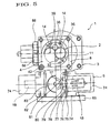
- Fig. 5 is an explanatory structural view as seen from the front side
- Fig. 6 is an explanatory structural view as seen from the left-hand side
- Fig. 7 is an explanatory structural view as seen at a drive position
- Fig. 5 is an explanatory structural view as seen from the front side
- Fig. 6 is an explanatory structural view as seen from the left-hand side
- Fig. 7 is an explanatory structural view as seen at a drive position
- Fig. 5 is an explanatory structural view as seen from the front side
- Fig. 8 is an explanatory structural view of a pump unit
- Fig. 9 is an exploded perspective view of the pump unit
- Fig. 10 is a front view of a front side main body casing integrated with a main body casing
- Fig. 11 is a sectional view of the front side main body casing
- Fig. 12 is a sectional view of the front side main body casing with a pressure guide path formed therein
- Fig. 13 is a view as seen in the direction of the arrow A in Fig. 10
- Fig. 14 is a sectional view taken along the line B-B of Fig. 13
- Fig. 15 is a sectional view of the front side main body casing at the drive position.
- reference numeral 1 indicates a servo type volumetric flowmeter employing a pump unit system according to the present invention (hereinafter referred to simply as volumetric flowmeter 1).
- the volumetric flowmeter 1 is equipped with a pump unit 2, which is detachable. Further, the volumetric flowmeter 1 has a route structure related to fluid flow and differential pressure detection suitable, in particular, for the case in which the pump unit 2 is provided.
- the construction of the volumetric flowmeter 1 will be described more specifically.
- the volumetric flowmeter 1 is equipped with the pump unit 2 as well as a main body casing 3 for accommodating the pump unit 2 and a cover member 4. Further, as shown in from Fig. 4 onward, the volumetric flowmeter 1 is further equipped with a shaft driving means 5, a differential pressure detecting means 6, and a control means 7.
- the arrow P indicates the vertical direction.
- the arrow Q indicates the horizontal direction, and the arrow R indicates the longitudinal direction. Those directions may or may not coincide with the direction in which the volumetric flowmeter 1 is mounted. (It should be noted, however, that a mounting direction in which piston 17 described below is set vertically is not permissible.)
- the main body casing 3 is equipped with a front side main body casing 8 having a structure which accommodates the pump unit 2 and integrates the differential pressure detecting means 6, and a rear side main body casing 10 which is connected to the front side main body casing 8 and in which it is possible to mount a servomotor 9 constituting the main body of the shaft driving means 5.
- a unit accommodating recess 11 for accommodating the pump unit 2.
- the pump unit 2 is inserted into the unit accommodating recess 11, and is then covered with the cover member 4 to be thereby completely accommodated.
- the volumetric flowmeter 1 allows maintenance, replacement or the like of the pump unit 2.
- reference numeral 12 indicates a pump portion.
- the pump portion 12 has a measuring chamber 13 and a pair of rotors 14.
- the pair of rotors 14 are arranged so as to be engaged with each other, and one of them is driven by the servomotor 9.
- the differential pressure detecting means 6 has a pair of differential pressure detection pressure guide paths 15 and a differential pressure detecting portion 16. Further, in this case, it has a piston 17, a light emission side photoelectric sensor (light emitting element) 18, and a light reception side photoelectric sensor (light receiving element) 19.
- the control means 7 has a computation circuit 20, a control circuit 21, and an output circuit 22.
- the fluid to be measured (which flows from the right to the left in the drawing) entering at an inlet 23 reaches an outlet 24 by way of the pair of rotors 14 of the pump portion 12.
- the pair of differential pressure detection pressure guide paths 15 On the output side and the input side of the pair of rotors 14 (i.e., on the left-hand side and the right-hand side in Fig. 4 ), there are provided the pair of differential pressure detection pressure guide paths 15; when a differential pressure is generated, the piston 17 accommodated in the differential pressure detecting portion 16 moves to the right or left. This movement of the piston 17 is observed by the light emission side photoelectric sensor 18 and the light reception side photoelectric sensor 19, and positional information on the piston 17 is transmitted to the computation circuit 20.
- the control circuit 21 In the computation circuit 20, there is generated a signal to be transmitted to the control circuit 21 so as to keep the differential pressure at zero, in other words, so as to stop the piston 17.
- the control circuit 21 is adapted to drive the servomotor 9 based on the signal from the computation circuit 20. Transmitted to the control circuit 21 is an encoder signal fed back from the servomotor 9. This encoder signal is transmitted to the output circuit 22, which outputs the encoder signal to the exterior as a flow rate signal (pulse output).
- volumetric flowmeter 1 The components of the volumetric flowmeter 1 will be described.
- the pump portion 12 is provided inside a pump portion casing 25 (see, for example, Figs. 8 and 9 ).
- the pump portion casing 25 is substantially formed as a cylinder whose thickness in the longitudinal direction is relatively small. In this embodiment, the ease of replacement at the time of flow rate range change is also taken into consideration, so the above-mentioned thickness is set to a fixed level.
- the substantially cylindrical configuration is given only by way of example. (There are no particular limitations regarding its configuration as long as the formation of pump portion 12 is possible and the attachment/detachment with respect to unit accommodating recess 11 (see Fig. 6 ) is easy to perform.)
- the pump portion casing 25 has three circular plates that are separable from each other. In order to give their names from the front side, they are: a cover member side plate 26, a middle plate 27, and a rotor shaft extension side plate 28. Those three plates are stacked together and fixed to each other by a plurality of screws (not indicated by reference numerals).
- the pump portion casing 25, constructed as described above, has rearwardly extending positioning pins 29 (the setting of which may be conducted arbitrarily).
- the positioning pins 29 are provided in order to allow smooth mating when inserting the pump unit 2 into the unit accommodating recess 11 (see Fig. 6 ) for accommodation.
- the pump unit 2 After positioning thereof at the unit accommodating recess 11, the pump unit 2 is fixed in position by mounting screws 30 passed through the pump portion casing 25 (see Fig. 6 ).
- the middle plate 27 has a measuring chamber forming portion 31 formed so as to extend therethrough (from the front side to the rear side) in conformity with the configuration of the measuring chamber 13 (see Fig. 8 ).
- the middle plate 27 of this embodiment is set to a thickness slightly larger than the thickness of the rotors 14.
- the cover member side plate 26 has a flat surface (rear surface) cover the front side opening of the measuring chamber forming portion 31.
- a pressure guide port 33 (see Fig. 8 ) extending therethrough so as to be matched with the position of a fluid inflow port 32 described below.
- the pressure guide port 33 is formed in order to guide a portion of the fluid to be measured entering at the fluid inflow port 32 to the unit accommodating recess 11 (see Fig. 6 ).
- the rotor shaft extension side plate 28 has a flat surface (front surface) covering the rear side opening of the measuring chamber forming portion 31. (When changing the flow rate range, it is possible to recess the front surface to form a part of the measuring chamber forming portion 31. In this case, several types of rotor shaft extension side plate 28 are prepared as replacement components.)
- the fluid inflow port 32 and a fluid outflow port 35 which communicate with the measuring chamber forming portion 31, in other words, with the measuring chamber 13, are formed in the rotor shaft extension side plate 28 so as extend therethrough. Further, also extending through the rotor shaft extension side plate 28 is a drive shaft through-hole 37 corresponding to a rearwardly extending rotor shaft 36 described below.
- the rotor shaft extension side plate 28 On the front surface of the rotor shaft extension side plate 28, there are provided two bearings 38 so as to be arranged horizontally side by side at a predetermined interval.
- One of the bearings 38 is provided in the drive shaft through-hole 37 (see Fig. 7 ).
- the rotor shaft 36 and a rotor shaft 39 of the rotors 14 are rotatably supported in a center-crank-like fashion by the bearings 38 of the rotor shaft extension side plate 28 and the bearings 34 of the cover member side plate 26.
- the pump portion 12 has the measuring chamber 13, the pair of rotors 14, and the rotor shafts 36, 39.
- the pair of rotors 14 are arranged so as to be engaged with each other, and the rotor shaft 36, which is provided on one of the rotors 14 constitutes the drive shaft and extends (rearwards) to the exterior through the drive shaft through-hole 37 (see Fig. 7 ).
- the fluid inflow port 32 and the fluid outflow port 35 are formed to be arranged respectively below and above the engagement portion between the pair of rotors 14.
- the fluid inflow port 32 is on the lower side
- the fluid outflow port 35 is on the upper side.
- the fluid inflow port 32 and the fluid outflow port 35 are formed so as to be arranged as close as possible to the engagement portion.
- the drive shaft through-hole 37 (see Fig. 7 ) is formed and arranged in conformity with position of the servomotor 9 (see Fig. 6 ).
- the drive shaft through-hole 37 is formed and arranged so that the center thereof is positioned on the center axis of the main body casing 3 (see Fig. 6 ).
- the front side main body casing 8 constituting the main body casing 3 has in the front surface thereof the unit accommodating recess 11 for accommodating the pump unit 2. Further, the front side main body casing 8 has in the left-hand side surface thereof a route portion related to the flow of the fluid to be measured. The route portion related to the flow of the fluid to be measured is formed so as to communicated with the unit accommodating recess 11. Further, the front side main body casing 8 has therebelow a portion for integrating the differential pressure detecting portion 6 therewith. This portion is formed such that the route related to differential pressure detection is continuous with the vicinity of the unit accommodating recess 11.
- the front side main body casing 8 has on the rear surface thereof a connecting portion for the rear side front body casing 10 and a portion related to a drive force transmitting portion 40 (see Fig. 7 ).
- the portion related to the drive force transmitting portion 40 is formed so as to be continuous with the unit accommodating recess 11.
- the unit accommodating recess 11 is formed in the front surface of the front side main body casing 8 so as to be a circular recess.
- the mounting of the cover member 4 is effected by fastening four bolts 42.
- the front side main body casing 8 (unit accommodating recess 11) has the function as a pressure container. That is, in the volumetric flowmeter 1, the pump unit 2 itself does not need to have the function of a pressure container.
- the reason for causing the above-mentioned components to function as a pressure container is to cause a portion of the fluid to be measured to flow into the unit accommodating recess 11 through the pressure guide port 33 (see Fig. 8 ), bringing also the outer side portion of the pump unit 2 into a wet state with the fluid filling the same. (The fluid pressures applied to the inner and outer sides of the pump unit 2 are equalized.)
- first inflow path 43 and a first outflow path 44 are formed as route portions related to the flow of the fluid to be measured.
- the first inflow path 43 is formed and arranged to be on the lower side, and the first outflow path 44 is formed and arranged to be on the upper side.
- An O-ring 45 is mounted to the periphery of the opening edge portion of the first outflow path 44 (see Fig. 10 ). The route portions related to the flow of the fluid to be measured will be described in detail below.
- a rotor shaft through-hole 46 so as to be matched with the position of the rotor shaft 36 extending from the pump unit 2 (see Fig. 15 ).
- the rotor shaft through-hole 46 is formed so as to be continuous with a pressure spacer mounting recess 47 open in the rear surface of the front side main body casing 8 (see Fig. 7 ).
- a pressure spacer 48 in the pressure spacer mounting recess 47, there is provided a pressure spacer 48 in a liquid-tight state (state in which the fluid to be measured is shut off).
- the unit accommodating recess 11 side and the servomotor 9 side are spaced apart from each other by the pressure spacer 48 (see Fig. 6 ).
- the rotor shaft through-hole 46, the pressure spacer mounting recess 47, and the pressure spacer 48 constitute the portion related to the drive force transmitting portion 40.
- Reference numeral 49 indicates a shaft coupling.
- Reference numeral 50 indicates a shaft coupling detent pin.
- Reference numeral 51 indicates a driven magnet shaft.
- Reference numeral 52 indicates a driven magnet detent pin.
- Reference numeral 53 indicates a driven magnet.
- Reference numeral 54 indicates an E-ring.
- Reference numeral 55 indicates a ball bearing.
- Reference numeral 56 indicates a driving magnet portion.
- Reference numeral 57 indicates a driving magnet mounting screw.
- Reference numeral 58 indicates a motor adapter.
- Reference numeral 59 indicates a motor adapter screw.
- Reference numeral 60 indicates motor mounting hardware.
- Reference numeral 61 indicates a reduction gear mounting bolt.
- Reference numeral 62 indicates a motor portion mounting bolt.
- the rotor shaft 36 extending from the pump unit 2 is driven by a magnetic coupling 63 formed by the driving magnet portion 56 and the driven magnet 53.
- a method by which the rotor shaft 36 is driven by using the magnetic coupling 63 so not only is there no fear of liquid leakage, but it is also possible to smoothly rotate the rotor shaft 36.
- the servomotor 9 existing at the rear of the portion related to the drive force transmitting portion 40 is mounted so as to be accommodated in a main body mounting portion 64 formed inside the rear side main body casing 10.
- the rear side main body casing 10 in which the main body mounting portion 64 is formed has an installation base 65 for installing the volumetric flowmeter 1 at a predetermined position, and extends to the portion for integrating the differential pressure detecting means 6 formed below the front side main body casing 8, making it possible to fix the differential pressure detecting means 6 in position.
- the route portion related to the flow of the fluid to be measured and the route portion related to the differential pressure detection will be described mainly with reference to Figs. 10 through 14 . First, the route portion related to the flow of the fluid to be measured will be described.
- the first outflow path 44 on the upper side is formed such that one end thereof is continuous with the fluid outflow port 35 of the pump unit 2.
- the first outflow path 44 is formed so as to extend straight rearwards from the depth (bottom) of the unit accommodating recess 11, that is, so as to extend parallel to the axial direction of the rotor shaft 36 extending from the pump unit 2.
- the length of the first outflow path 44 is set minimum. In this embodiment, the length is set such that the position of the other end of the first outflow path 44 is on the front side of the central position in the longitudinal direction of the front side main body casing 8.
- a first inflow path 43 on the lower side is formed such that one end thereof is continuous with the fluid inflow port 32 of the pump unit 2.
- the first inflow path 43 is formed so as to extend straight rearwards from the depth (bottom) of the unit accommodating recess 11, that is, so as to extend parallel to the axial direction of the rotor shaft 36 extending from the pump unit 2. Further, the first inflow path 43 is formed so as to be parallel to the first outflow path 44 on the upper side.
- the first inflow path 43 is formed so as to be somewhat shorter than the first outflow path 44 on the upper side.
- the description of the first inflow path 43 and the first outflow path 44 will be summarized.
- the first inflow path 43 and the first outflow path 44 are open in the size of the fluid inflow port 32 and the flow outflow port 35, and are parallel to each other while maintaining a fixed distance therebetween. Further, the first outflow path 44 is formed so as to extend somewhat longer rearwards.
- a second outflow path 66 is formed so as to be continuous with the first outflow path 44 on the upper side (see Figs. 12 , 14 ).
- the second outflow path 66 is formed so as to extend straight in a direction orthogonal to (to the left in this embodiment) with respect to the axial direction of the rotor shaft 36 extending from the pump unit 2.
- the second outflow path 66 is formed such that one end thereof is continuous with the first outflow path 44 and that the other end thereof is open in the left-hand side surface of the front side main body casing 8.
- the second outflow path 66 is formed so as to open in the same size as the first outflow path 44.
- the second outflow path 66 and the first outflow path 44 are formed as substantially L-shaped routes.
- a second inflow path 67 is formed so as to be continuous with the first inflow path 43 on the lower side.
- the second inflow path 67 is formed so as to extend straight in a direction orthogonal to (to the left in this embodiment) with respect to the axial direction of the rotor shaft 36 extending from the pump unit 2. Further, the second inflow path 67 is formed so as to be parallel to the second outflow path 66.
- the second inflow path 67 is formed such that one end thereof is continuous with the first inflow path 43 and that the other end thereof is open in the left-hand side surface of the front side main body casing 8.
- the second inflow path 67 is formed so as to open in the same size as the first inflow path 43.
- the second inflow path 67 and the first inflow path 43 are formed as substantially L-shaped routes.
- the description of the second inflow path 67 and the second outflow path 66 will be summarized.
- the second inflow path 67 and the second outflow path 66 are open in the size of the fluid inflow port 32 and the flow outflow port 35, respectively, and are parallel to each other while maintaining a fixed distance therebetween, extending in the same length to open in the left-hand surface of the front side main body casing 8.
- the route portion related to the flow of the fluid to be measured is constituted by the substantially L-shaped route formed by the second outflow path 66 and the first outflow path 44 and the substantially L-shaped path formed by the second inflow path 67 and the fist inflow path 43.
- a joint 68 is mounted to each of the opening portions of the second outflow path 66 and the second inflow path 67 in the left-hand side surface of the front side main body casing 8.
- the first outflow path 44 corresponds to the opening end portion of the outflow path opening in the unit accommodating recess 11.
- the first inflow path 43 corresponds to the inflow path opening in the unit accommodating recess 11.
- a continuation center position 69 of the second outflow path 66 and the first outflow path 44 and a continuation center position 70 of the second inflow path 67 and the first inflow path 43 are set so as to be arranged vertically.
- the continuation center position 70 is set in conformity with the other end position of the first inflow path 43.
- the first outflow path 44 has some space on the rear side of the continuation center position 69. This space is used for differential pressure detection. This is why the first outflow path 44 is set somewhat longer than the first inflow path 43.
- One differential pressure detection pressure guide path 71 (corresponding to differential pressure detection pressure guide path 15 of Fig. 4 ) is formed so as to be continuous with the first inflow path 43 on the lower side.
- the one differential pressure detection pressure guide path 71 is formed such that one end thereof is open between the continuation center position 70 of the second inflow path 67 and the first inflow path 43 and one end of the first inflow path 43.
- One end of the one differential pressure detection pressure guide path 71 has the function of a differential pressure extraction port.
- the one differential pressure detection pressure guide path 71 is formed so as to extend straightly downwards.
- the one differential pressure detection pressure guide path 71 is a path for detecting differential pressure, and its diameter is set smaller than that of the first inflow path 43.
- the other differential pressure detection pressure guide path 72 (corresponding to differential pressure detection pressure guide path 15 of Fig. 4 ) is formed so as to be continuous with the first outflow path 44 on the upper side.
- the other differential pressure detection pressure guide path 72 is formed such that one end thereof is open at a position more spaced apart from the fluid outflow port 35 with respect to the continuation center position 69 of the second outflow path 66 and the first outflow path 44.
- One end of the other differential pressure detection pressure guide path 72 has the function of a differential pressure extraction port.
- the other differential pressure detection pressure guide path 72 is formed in conformity with the end portion position of the first outflow path 44.
- the other differential pressure detection pressure guide path 72 is formed so as to extend straightly downwards.
- the other differential pressure detection pressure guide path 72 is formed so as to be parallel to the one differential pressure detection pressure guide path 71.
- the other differential pressure detection pressure guide path 72 is a path for detecting differential pressure, and its diameter is set smaller than that of the first outflow path 44.
- the description of the one differential pressure detection pressure guide path 71 and the other differential pressure detection pressure guide path 72 will be summarized.
- the one differential pressure detection pressure guide path 71 and the other differential pressure detection pressure guide path 72 are formed so as to be arranged longitudinally side by side at a predetermined interval. Further, the one differential pressure detection pressure guide path 71 is connected on the front side of the continuation center position 70 of the second inflow path 67 and the first inflow path 43, and the other differential pressure detection pressure guide path 72 is connected on the rear side of the continuation center position 69 of the second outflow path 66 and the first outflow path 44.
- the connecting positions are set aiming at an arrangement of high efficiency for the piston 17, etc.
- the differential pressure detecting means 6 (whereby it is advantageously possible to achieve a reduction in the longitudinal dimension of the volumetric flowmeter 1 even if the differential pressure detecting means 6 is integrated with the front side main body casing 8. (For example, if the one differential pressure detection pressure guide path 71 is shifted rearwards, it is necessary to shift the components of the differential pressure detecting means 6 rearwards by this shifting amount, resulting in a rearwardly enlarged structure).)
- a differential pressure detecting portion 73 (corresponding to the differential pressure detecting portion 16 of Fig. 4 ) is formed at the other ends of the one differential pressure detection pressure guide path 71 and the other differential pressure detection pressure guide path 72 so as to be continuous therewith.
- Reference numeral 17 indicates a piston.
- Reference numeral 18 indicates a light emission side photoelectric sensor.
- Reference numeral 19 indicates a light emission side photoelectric sensor. Those are basically the same as those shown in Fig. 4 .
- Reference numeral 74 indicates a photoelectric sensor case (see Fig. 5 ).
- Reference numeral 75 indicates a photoelectric sensor mounting plate.
- Reference numeral 76 indicates photoelectric sensor packing.
- Reference numeral 77 indicates glass-paned window packing.
- Reference numeral 78 indicates a photoelectric sensor mounting bolt.
- Reference numeral 79 indicates tempered glass.
- Reference numeral 80 indicates a tempered glass O-ring.
- Reference numeral 81 indicates a photoelectric sensor positioning pin.
- Reference numeral 82 indicates photoelectric sensor case mounting bolts.
- Reference numeral 83 indicates a cylinder front side cover.
- Reference numeral 84 indicates a sleeve (see Fig. 6 ).
- Reference numeral 85 indicates a cylinder cover O-ring.
- Reference numeral 86 indicates a cylinder rear side cover.
- the sleeve 84 has a portion 87 matching a part of the other differential pressure detection pressure guide path 72 with the position of the piston 17.
- the volumetric flowmeter 1 has a construction in which the pump unit 2 having the pump portion 12 is accommodated in the unit accommodating recess 11 of the main body casing 3 (front side main body casing 8) to be covered with the cover member 4, with the unit accommodating recess 11 and the cover member 4 forming a portion functioning as a pressure container.
- the pump unit 2 has a construction in which the fluid to be measured flows within the inner space thereof and in which the entire outer space thereof is filled with the fluid to be measured. In the pump unit 2, the fluid pressures applied to the inner and outer side thereof are equalized.
- the volumetric flowmeter 1 it is the cover member 4 functioning, for example, as a pressure container that undergoes temporary deformation due to fluid pressure, and the pump unit 2 itself undergoes no deformation.
- the volumetric flowmeter 1 is capable of high precision measurement. Apart from this, the volumetric flowmeter 1 provides the following effects.
- the pump portion casing 25 of the pump unit 2 In the volumetric flowmeter 1, there is no need for the pump portion casing 25 of the pump unit 2 to be formed as a pressure container, so it is possible to reduce the wall thickness, for example, of the pump portion casing 25. Thus, the pump unit 2 can be relatively small. (By making the size of the pump unit 2 relatively small, it is also possible to realize a satisfactory workability at the time of replacement.)
- the volumetric flowmeter 1 helps to achieve an improvement in terms of performance and maintenance. (Although there is not yielded such effects, it is also possible to adopt a construction in which driving is effected by using a conventional seal member.)
- the volumetric flowmeter 1 can stabilize the rotation of the rotors 14. Due to the center-crank-like structure of the rotor shafts 36, 39, there is no need to set the axial length large as in the case of the cantilever-like structure, with the result that it is possible to reduce the size of the pump portion 12.
- the pump portion casing 25 of the pump unit 2 is formed by three separable plates, one of which can be replaced according to the size of the rotors 14, so it is also possible to take into consideration the ease with which replacement is performed when the flow rate range is changed.
- the position where differential pressure is extracted is close to the pump portion 12, and the differential pressure detecting means 6 is integrated with the main body casing 3 (front side main body casing 8), so it is possible to enhance the precision in differential pressure detection as compared with that in the prior art.
Landscapes
- Physics & Mathematics (AREA)
- Fluid Mechanics (AREA)
- General Physics & Mathematics (AREA)
- Measuring Volume Flow (AREA)
- Structures Of Non-Positive Displacement Pumps (AREA)
Claims (6)
- Ein Servo-Volumendurchfluß-Meßgerät (1), das eine Pumpeinheit verwendet, mit einer Pumpeinheit (2), die dadurch gebildet ist, dass im Inneren ein Pumpabschnittsgehäuse (12), ein Pumpenabschnitt (12), der einen ersten Rotor (14) und einen zweiten Rotor (14) mit Rotorwellen (36, 39) aufweist und eine Messkammer (13), die so angeordnet ist, um den ersten Rotor (14) und den zweiten Rotor (14) zu umschließen, vorgesehen sind, wobei die Pumpeinheit (2) folgendes aufweist:einen Fluideinlassanschluss (32), der mit der Messkammer (13) verbunden ist,einen Fluidauslassanschluss (35),wobei eine der Rotorwellen (36) aus dem Pumpabschnittsgehäuse (25) alsAntriebswelle (36) herausragt,wobei das Servo-Volumendurchfluss-Messgerät (1) mit der oben beschriebenen Pumpeinheit (2) weiterhin ausgestattet ist mit:einem Hauptkörpergehäuse (3), das die Pumpeinheit (2) beinhaltet,einem Einströmpfad (43, 67), der in dem Hauptkörpergehäuse (3) ausgebildet ist und eine zu messende Flüssigkeit in Richtung Pumpeinheit (2) führt,einem Ausströmpfad (44, 66), der in dem Hauptkörpergehäuse (3) ausgebildet ist und die zu messende Flüssigkeit nach Außen bezüglich des Hauptkörpergehäuses (3) von der Pumpeinheit (2) führt,einer Wellenantriebseinrichtung (5), die an dem Hauptkörpergehäuse (3) angebracht ist und die eine der Rotorwellen (36), die aus dem Pumpabschnittsgehäuse (25) hervorsteht, antreibt,einer Differenzdruckerfassungseinrichtung (6) zum Erfassen einer Druckdifferenz zwischen der Vorder- und Rückseite des ersten Rotors (14) unddes zweiten Rotors (14), undeine Regeleinrichtung (7) zum Regeln der Wellenantriebseinriehtung (5)ausgehend von der Druckdifferenz,dadurch gekennzeichnet, dassdas Hauptkörpergehäuse (3) eine Aufnahmevertiefungseinheit (11) hat, die dann abnehmbar ausgebildet ist und die Pumpeinheit (2) aufnimmt, wobeidas Servo-Volumendurchffuss-Messgerät (1) ferner mit einem Abdeckelement (4) ausgestattet ist, das die Aufnahmevertiefungseinheit (11) abdeckt, die an dem Hauptkörpergehäuse (3) befestigt ist,wobei das Pumpabschnittsgehäuse (25) der Pumpeinheit (2), das in der Aufnahmevertiefungseinheit (11) untergebracht ist und mit dem Abdeckelement (4) bedeckt ist, einen Druckführungsanschluss (33) aufweist, der einen Teil des zu messenden Fluids derart leitet, dass es an dem Fluideinströmanschluss (32) eintritt, wobei der Fluiddruck an der Innen- und Außenseite der Pumpeinheit (2) ausgeglichen ist.
- Ein Servo-Volumendurchfluss-Messgerät (1), das eine Pumpeinheit verwendet, nach Anspruch 1, wobei ein Hauptbefestigungabschnitt (64), der an dem Hauptkörpergehäuse (3) angeordnet ist, um den Hauptkörper der Wellenantriebseinrichtung (5) aufzunehmen, von der Aufnahmevertiefungseinheit (11) isoliert ist, um das zu messende Fluid abzutrennen, und wobei die Wellenantriebseinrichtung (5) derart ausgebildet ist, dass eine der Rotorwellen (36) durch einen magnetischen Anschluss (63) angetrieben wird.
- Ein Servo-Volumendurchfluss-Messgerät (1), das eine Pumpeinheit verwendet, nach Anspruch 1 oder 2, wobei die Rotorwellen (36) des ersten Rotors (14) und des zweiten Rotors (14) in der Art einer zentralen Kurbelanordnung bezüglich des Pumpengehäuses (25) gelagert sind.
- Ein Servo-Volumendurchfluss-Messgerät (1), das eine Pumpeinheit verwendet, nach einem der Ansprüche 1 bis 3, wobei das Pumpabschnittsgehäuse (25) mit drei separierbaren Platten (26, 27; 28) bestückt ist, zusammengesetzt aus:- einer mittleren Platte (27), die einen eine Messkammer bildenden Abschnitt (31) aufweist, der sich in Konformität mit der Konfiguration der Messkammer (13) hindurch erstreckt,- eine Abdeckungselementseitenplatte (26), die eine flache Oberfläche aufweist, die eine Öffnung des die Messkammerbildenden Abschnitts (31) abdeckt, und- eine austauschbare Rotorwellenextensionsseitenplatte abdeckt (28), die eine flache Oberfläche aufweist, die die andere Öffnung des Messkammer formenden Abschnitts (31) oder eine Vertiefung, die einen Teil der Messkammer (13) darstellt, abdeckt, und- mehrere Schrauben, um die drei zusammengesteckten Platten (26, 27; 28), aneinander zu fixieren, und- wobei das Pumpabschnittsgehäuse (25), wenn die drei Platten (26, 27; 28) zusammengesteckt sind, eine feste Dicke hat und abnehmbar bezüglich der Aufnahmevertiefungseinheit (11) ist.
- Ein Servo-Volumendurchfluss-Messgerät (1), das eine Pumpeinheit verwendet, nach einem der Ansprüche 1 bis 4, wobei das Hauptkörpergehäuse (3) ein Paar von Differentialdruckdetektions- und Druckführungspfaden (15) aufweist, wobei jeder der beiden an einem Ende einen Differentialdruckauslassanschluss zur Differentialdruckdetektion und einen Differentialdruckdetektionsabschnitt (16; 73) aufweist, zusammenhängende mit den anderen Enden der Differentialdruckdetektions- und Druckführungspfäden (15), und wobei die Diffemtialdruckdetektionseinrichtung (6) mit dem Hauptkörpergehäuse (3) an einer Position in einer Nähe der Aufnahmevertiefungseinheit (11) integriert ist.
- Ein Servo-Volumendurchfluss-Messgerät (1), das eine Pumpeinheit verwendet, nach Anspruch 5, wobei der Differentialdruckdetektionsanschluss in dem Einströmpfad (43, 67) ausgebildet ist, und wobei der Ausströmpfad (44, 66) sich in die Aufnahmevertiefungseinheit (11) öffnet.
Applications Claiming Priority (2)
| Application Number | Priority Date | Filing Date | Title |
|---|---|---|---|
| JP2007025185A JP4246237B2 (ja) | 2007-02-05 | 2007-02-05 | ポンプユニット式サーボ型容積流量計 |
| PCT/JP2008/051608 WO2008096666A1 (ja) | 2007-02-05 | 2008-01-25 | ポンプユニット式サーボ型容積流量計 |
Publications (3)
| Publication Number | Publication Date |
|---|---|
| EP2128574A1 EP2128574A1 (de) | 2009-12-02 |
| EP2128574A4 EP2128574A4 (de) | 2010-08-11 |
| EP2128574B1 true EP2128574B1 (de) | 2012-10-03 |
Family
ID=39681577
Family Applications (1)
| Application Number | Title | Priority Date | Filing Date |
|---|---|---|---|
| EP08704317A Active EP2128574B1 (de) | 2007-02-05 | 2008-01-25 | Servo-verschiebungsströmungsmesser des pumpeinheittyps |
Country Status (6)
| Country | Link |
|---|---|
| US (1) | US7905142B2 (de) |
| EP (1) | EP2128574B1 (de) |
| JP (1) | JP4246237B2 (de) |
| KR (1) | KR101057560B1 (de) |
| CN (1) | CN101606042B (de) |
| WO (1) | WO2008096666A1 (de) |
Families Citing this family (10)
| Publication number | Priority date | Publication date | Assignee | Title |
|---|---|---|---|---|
| JP4183096B2 (ja) * | 2007-02-05 | 2008-11-19 | 株式会社オーバル | サーボ型容積流量計における被測定流体の流れと差圧検出とに係る経路構造 |
| AT512027B1 (de) | 2013-01-30 | 2014-04-15 | Avl List Gmbh | Durchflussmessgerät |
| AT512619B1 (de) * | 2013-06-26 | 2015-02-15 | Avl List Gmbh | Durchflussmessgerät |
| CN103552465A (zh) * | 2013-11-05 | 2014-02-05 | 宁夏新航能源环境科技有限公司 | 一种节能型液压系统 |
| AT516622B1 (de) | 2015-03-24 | 2016-07-15 | Avl List Gmbh | System zur Messung von zeitlich aufgelösten Durchflussvorgängen von Fluiden |
| AT517817B1 (de) * | 2015-09-15 | 2017-08-15 | Avl List Gmbh | Vorrichtung mit Spalttopfmotor zur Messung von Durchflussvorgängen von Messfluiden |
| AT517819B1 (de) * | 2015-09-15 | 2017-08-15 | Avl List Gmbh | Spülbare Vorrichtung zur Messung von Durchflussvorgängen von Fluiden |
| AT517707B1 (de) * | 2016-01-29 | 2017-04-15 | Avl List Gmbh | Antriebs- und Steuervorrichtung für ein Durchflussmessgerät |
| DE102017004450A1 (de) * | 2017-05-09 | 2018-11-15 | Diehl Metering Gmbh | Anordnung zum Einbau in ein Fluidleitungsnetz |
| US11602589B2 (en) * | 2019-05-21 | 2023-03-14 | Covidien Lp | Peristaltic pumps with selective activation of multiple fluid lines and fluid management systems including the same |
Family Cites Families (19)
| Publication number | Priority date | Publication date | Assignee | Title |
|---|---|---|---|---|
| US2809492A (en) * | 1952-12-23 | 1957-10-15 | Simmonds Aerocessories Inc | Apparatus for measuring and/or controlling fuel/air ratio of gas turbines without direct gravimetric fuel metering |
| US3015233A (en) * | 1958-07-22 | 1962-01-02 | Simmonds Aerocessories Inc | Mass flowmeter |
| US3266309A (en) * | 1962-12-19 | 1966-08-16 | Flotron Inc | Mass flowmeter |
| US3583220A (en) * | 1968-06-20 | 1971-06-08 | Oval Eng Co Ltd | Flowmeter |
| US3699812A (en) * | 1971-01-29 | 1972-10-24 | Walter Masnik | Mass flowmeter |
| US4062236A (en) * | 1976-05-03 | 1977-12-13 | Precision Machine Products, Inc. | Method of and means for accurately measuring the calorific value of combustible gases |
| JPS57104320U (de) | 1980-12-19 | 1982-06-26 | ||
| JPS57104320A (en) | 1980-12-22 | 1982-06-29 | Nec Corp | Digital-analogue converter |
| US4627267A (en) * | 1985-07-19 | 1986-12-09 | Flow Technology, Inc. | Apparatus and method for determining the flow characterstic of a volumetric flowmeter |
| JPS6251231A (ja) | 1985-08-30 | 1987-03-05 | Fujitsu Ltd | 半導体集積回路装置 |
| JPH0323534Y2 (de) | 1985-09-20 | 1991-05-22 | ||
| US4916949A (en) * | 1989-05-03 | 1990-04-17 | Lofink Joseph P | Gas flow meter |
| US5284053A (en) * | 1992-01-10 | 1994-02-08 | The Boc Group, Inc. | Controlled flow volumetric flowmeter |
| DE4211740A1 (de) * | 1992-04-03 | 1993-10-07 | Daniel Messtechnik Gmbh Babels | Einrichtung zur Übertragung der Drehbewegung bei Ovalrad-Mengenmessern |
| JP2878555B2 (ja) * | 1993-03-30 | 1999-04-05 | 株式会社オーバル | サーボ形容積流量計 |
| US5992230A (en) * | 1997-11-15 | 1999-11-30 | Hoffer Flow Controls, Inc. | Dual rotor flow meter |
| JP3331212B2 (ja) | 2000-09-07 | 2002-10-07 | 株式会社オーバル | サーボ形容積式流量計 |
| FR2882098B1 (fr) * | 2005-02-17 | 2011-07-15 | Hispano Suiza Sa | Regulation du debit de carburant alimentant un moteur a turbine a gaz |
| JP4183096B2 (ja) * | 2007-02-05 | 2008-11-19 | 株式会社オーバル | サーボ型容積流量計における被測定流体の流れと差圧検出とに係る経路構造 |
-
2007
- 2007-02-05 JP JP2007025185A patent/JP4246237B2/ja active Active
-
2008
- 2008-01-25 CN CN2008800041714A patent/CN101606042B/zh not_active Expired - Fee Related
- 2008-01-25 US US12/521,796 patent/US7905142B2/en active Active
- 2008-01-25 WO PCT/JP2008/051608 patent/WO2008096666A1/ja not_active Ceased
- 2008-01-25 EP EP08704317A patent/EP2128574B1/de active Active
- 2008-01-25 KR KR1020097013684A patent/KR101057560B1/ko not_active Expired - Fee Related
Also Published As
| Publication number | Publication date |
|---|---|
| US20100043568A1 (en) | 2010-02-25 |
| EP2128574A1 (de) | 2009-12-02 |
| JP2008190982A (ja) | 2008-08-21 |
| EP2128574A4 (de) | 2010-08-11 |
| WO2008096666A1 (ja) | 2008-08-14 |
| CN101606042B (zh) | 2011-10-12 |
| US7905142B2 (en) | 2011-03-15 |
| CN101606042A (zh) | 2009-12-16 |
| KR20090092829A (ko) | 2009-09-01 |
| JP4246237B2 (ja) | 2009-04-02 |
| KR101057560B1 (ko) | 2011-08-17 |
Similar Documents
| Publication | Publication Date | Title |
|---|---|---|
| EP2128574B1 (de) | Servo-verschiebungsströmungsmesser des pumpeinheittyps | |
| US7905141B2 (en) | Path structure related to flow of fluid to be measured and pressure difference detection in servo type volumetric flowmeter | |
| CN201163202Y (zh) | 一种罗茨流量计 | |
| KR101771214B1 (ko) | 용적식 유량계 | |
| KR101924426B1 (ko) | 가스계량기용 누출 점검기 | |
| JP3063809B2 (ja) | 容積流量計 | |
| CN217155491U (zh) | 一种阀控式超声波流量计 | |
| JP3667314B2 (ja) | 容積式流量計 | |
| CN115949776A (zh) | 一种带微流路的旋转分配阀装置 | |
| KR101488277B1 (ko) | 용량식 유량계 | |
| CN115290154B (zh) | 容积式水表 | |
| JP4245414B2 (ja) | 回転検出器、容積式流量計、及び回転検出方法 | |
| CN108827413B (zh) | 一种罗茨流量计 | |
| CN215491915U (zh) | 一种立式水表表壳和阀门腔体一体化的流速测量装置 | |
| JP4881066B2 (ja) | 流量計 | |
| KR101479648B1 (ko) | 용적식 유량계 | |
| KR20150017822A (ko) | 수도계량기 | |
| CN115307691A (zh) | 流量计量机构及容积式水表 | |
| KR20180092229A (ko) | 로터 및 피스톤 방식의 용적식 유량계 | |
| KR20000018511U (ko) | 용적식 유량계 | |
| KR20140134413A (ko) | 수도계량기 | |
| CN116592954A (zh) | 一种特殊结构计量方式的流量计 | |
| JP2010066104A (ja) | マグネットカップリング装置およびこれを用いたメータ | |
| KR20150107084A (ko) | 수도계량기 |
Legal Events
| Date | Code | Title | Description |
|---|---|---|---|
| PUAI | Public reference made under article 153(3) epc to a published international application that has entered the european phase |
Free format text: ORIGINAL CODE: 0009012 |
|
| 17P | Request for examination filed |
Effective date: 20090819 |
|
| AK | Designated contracting states |
Kind code of ref document: A1 Designated state(s): AT BE BG CH CY CZ DE DK EE ES FI FR GB GR HR HU IE IS IT LI LT LU LV MC MT NL NO PL PT RO SE SI SK TR |
|
| DAX | Request for extension of the european patent (deleted) | ||
| A4 | Supplementary search report drawn up and despatched |
Effective date: 20100713 |
|
| RIC1 | Information provided on ipc code assigned before grant |
Ipc: G01F 15/02 20060101ALI20100707BHEP Ipc: G01F 3/10 20060101AFI20080828BHEP |
|
| GRAP | Despatch of communication of intention to grant a patent |
Free format text: ORIGINAL CODE: EPIDOSNIGR1 |
|
| GRAS | Grant fee paid |
Free format text: ORIGINAL CODE: EPIDOSNIGR3 |
|
| GRAA | (expected) grant |
Free format text: ORIGINAL CODE: 0009210 |
|
| AK | Designated contracting states |
Kind code of ref document: B1 Designated state(s): AT BE BG CH CY CZ DE DK EE ES FI FR GB GR HR HU IE IS IT LI LT LU LV MC MT NL NO PL PT RO SE SI SK TR |
|
| REG | Reference to a national code |
Ref country code: GB Ref legal event code: FG4D |
|
| REG | Reference to a national code |
Ref country code: AT Ref legal event code: REF Ref document number: 578173 Country of ref document: AT Kind code of ref document: T Effective date: 20121015 Ref country code: CH Ref legal event code: EP |
|
| REG | Reference to a national code |
Ref country code: IE Ref legal event code: FG4D |
|
| REG | Reference to a national code |
Ref country code: DE Ref legal event code: R096 Ref document number: 602008019128 Country of ref document: DE Effective date: 20121129 |
|
| REG | Reference to a national code |
Ref country code: AT Ref legal event code: MK05 Ref document number: 578173 Country of ref document: AT Kind code of ref document: T Effective date: 20121003 |
|
| PG25 | Lapsed in a contracting state [announced via postgrant information from national office to epo] |
Ref country code: SI Free format text: LAPSE BECAUSE OF FAILURE TO SUBMIT A TRANSLATION OF THE DESCRIPTION OR TO PAY THE FEE WITHIN THE PRESCRIBED TIME-LIMIT Effective date: 20121003 |
|
| REG | Reference to a national code |
Ref country code: NL Ref legal event code: VDEP Effective date: 20121003 |
|
| REG | Reference to a national code |
Ref country code: LT Ref legal event code: MG4D |
|
| PG25 | Lapsed in a contracting state [announced via postgrant information from national office to epo] |
Ref country code: ES Free format text: LAPSE BECAUSE OF FAILURE TO SUBMIT A TRANSLATION OF THE DESCRIPTION OR TO PAY THE FEE WITHIN THE PRESCRIBED TIME-LIMIT Effective date: 20130114 Ref country code: FI Free format text: LAPSE BECAUSE OF FAILURE TO SUBMIT A TRANSLATION OF THE DESCRIPTION OR TO PAY THE FEE WITHIN THE PRESCRIBED TIME-LIMIT Effective date: 20121003 Ref country code: NO Free format text: LAPSE BECAUSE OF FAILURE TO SUBMIT A TRANSLATION OF THE DESCRIPTION OR TO PAY THE FEE WITHIN THE PRESCRIBED TIME-LIMIT Effective date: 20130103 Ref country code: SE Free format text: LAPSE BECAUSE OF FAILURE TO SUBMIT A TRANSLATION OF THE DESCRIPTION OR TO PAY THE FEE WITHIN THE PRESCRIBED TIME-LIMIT Effective date: 20121003 Ref country code: NL Free format text: LAPSE BECAUSE OF FAILURE TO SUBMIT A TRANSLATION OF THE DESCRIPTION OR TO PAY THE FEE WITHIN THE PRESCRIBED TIME-LIMIT Effective date: 20121003 Ref country code: LT Free format text: LAPSE BECAUSE OF FAILURE TO SUBMIT A TRANSLATION OF THE DESCRIPTION OR TO PAY THE FEE WITHIN THE PRESCRIBED TIME-LIMIT Effective date: 20121003 Ref country code: IS Free format text: LAPSE BECAUSE OF FAILURE TO SUBMIT A TRANSLATION OF THE DESCRIPTION OR TO PAY THE FEE WITHIN THE PRESCRIBED TIME-LIMIT Effective date: 20130203 Ref country code: HR Free format text: LAPSE BECAUSE OF FAILURE TO SUBMIT A TRANSLATION OF THE DESCRIPTION OR TO PAY THE FEE WITHIN THE PRESCRIBED TIME-LIMIT Effective date: 20121003 |
|
| PG25 | Lapsed in a contracting state [announced via postgrant information from national office to epo] |
Ref country code: PL Free format text: LAPSE BECAUSE OF FAILURE TO SUBMIT A TRANSLATION OF THE DESCRIPTION OR TO PAY THE FEE WITHIN THE PRESCRIBED TIME-LIMIT Effective date: 20121003 Ref country code: LV Free format text: LAPSE BECAUSE OF FAILURE TO SUBMIT A TRANSLATION OF THE DESCRIPTION OR TO PAY THE FEE WITHIN THE PRESCRIBED TIME-LIMIT Effective date: 20121003 Ref country code: CY Free format text: LAPSE BECAUSE OF FAILURE TO SUBMIT A TRANSLATION OF THE DESCRIPTION OR TO PAY THE FEE WITHIN THE PRESCRIBED TIME-LIMIT Effective date: 20121003 Ref country code: BE Free format text: LAPSE BECAUSE OF FAILURE TO SUBMIT A TRANSLATION OF THE DESCRIPTION OR TO PAY THE FEE WITHIN THE PRESCRIBED TIME-LIMIT Effective date: 20121003 Ref country code: GR Free format text: LAPSE BECAUSE OF FAILURE TO SUBMIT A TRANSLATION OF THE DESCRIPTION OR TO PAY THE FEE WITHIN THE PRESCRIBED TIME-LIMIT Effective date: 20130104 Ref country code: PT Free format text: LAPSE BECAUSE OF FAILURE TO SUBMIT A TRANSLATION OF THE DESCRIPTION OR TO PAY THE FEE WITHIN THE PRESCRIBED TIME-LIMIT Effective date: 20130204 |
|
| PG25 | Lapsed in a contracting state [announced via postgrant information from national office to epo] |
Ref country code: AT Free format text: LAPSE BECAUSE OF FAILURE TO SUBMIT A TRANSLATION OF THE DESCRIPTION OR TO PAY THE FEE WITHIN THE PRESCRIBED TIME-LIMIT Effective date: 20121003 |
|
| PG25 | Lapsed in a contracting state [announced via postgrant information from national office to epo] |
Ref country code: DK Free format text: LAPSE BECAUSE OF FAILURE TO SUBMIT A TRANSLATION OF THE DESCRIPTION OR TO PAY THE FEE WITHIN THE PRESCRIBED TIME-LIMIT Effective date: 20121003 Ref country code: SK Free format text: LAPSE BECAUSE OF FAILURE TO SUBMIT A TRANSLATION OF THE DESCRIPTION OR TO PAY THE FEE WITHIN THE PRESCRIBED TIME-LIMIT Effective date: 20121003 Ref country code: EE Free format text: LAPSE BECAUSE OF FAILURE TO SUBMIT A TRANSLATION OF THE DESCRIPTION OR TO PAY THE FEE WITHIN THE PRESCRIBED TIME-LIMIT Effective date: 20121003 Ref country code: BG Free format text: LAPSE BECAUSE OF FAILURE TO SUBMIT A TRANSLATION OF THE DESCRIPTION OR TO PAY THE FEE WITHIN THE PRESCRIBED TIME-LIMIT Effective date: 20130103 Ref country code: CZ Free format text: LAPSE BECAUSE OF FAILURE TO SUBMIT A TRANSLATION OF THE DESCRIPTION OR TO PAY THE FEE WITHIN THE PRESCRIBED TIME-LIMIT Effective date: 20121003 |
|
| PLBE | No opposition filed within time limit |
Free format text: ORIGINAL CODE: 0009261 |
|
| STAA | Information on the status of an ep patent application or granted ep patent |
Free format text: STATUS: NO OPPOSITION FILED WITHIN TIME LIMIT |
|
| PG25 | Lapsed in a contracting state [announced via postgrant information from national office to epo] |
Ref country code: IT Free format text: LAPSE BECAUSE OF FAILURE TO SUBMIT A TRANSLATION OF THE DESCRIPTION OR TO PAY THE FEE WITHIN THE PRESCRIBED TIME-LIMIT Effective date: 20121003 Ref country code: RO Free format text: LAPSE BECAUSE OF FAILURE TO SUBMIT A TRANSLATION OF THE DESCRIPTION OR TO PAY THE FEE WITHIN THE PRESCRIBED TIME-LIMIT Effective date: 20121003 Ref country code: MC Free format text: LAPSE BECAUSE OF NON-PAYMENT OF DUE FEES Effective date: 20130131 |
|
| REG | Reference to a national code |
Ref country code: CH Ref legal event code: PL |
|
| 26N | No opposition filed |
Effective date: 20130704 |
|
| GBPC | Gb: european patent ceased through non-payment of renewal fee |
Effective date: 20130125 |
|
| REG | Reference to a national code |
Ref country code: IE Ref legal event code: MM4A |
|
| REG | Reference to a national code |
Ref country code: FR Ref legal event code: ST Effective date: 20130930 |
|
| PG25 | Lapsed in a contracting state [announced via postgrant information from national office to epo] |
Ref country code: LI Free format text: LAPSE BECAUSE OF NON-PAYMENT OF DUE FEES Effective date: 20130131 Ref country code: CH Free format text: LAPSE BECAUSE OF NON-PAYMENT OF DUE FEES Effective date: 20130131 |
|
| REG | Reference to a national code |
Ref country code: DE Ref legal event code: R097 Ref document number: 602008019128 Country of ref document: DE Effective date: 20130704 |
|
| REG | Reference to a national code |
Ref country code: HU Ref legal event code: AG4A Ref document number: E017164 Country of ref document: HU |
|
| PG25 | Lapsed in a contracting state [announced via postgrant information from national office to epo] |
Ref country code: FR Free format text: LAPSE BECAUSE OF NON-PAYMENT OF DUE FEES Effective date: 20130131 Ref country code: GB Free format text: LAPSE BECAUSE OF NON-PAYMENT OF DUE FEES Effective date: 20130125 |
|
| PG25 | Lapsed in a contracting state [announced via postgrant information from national office to epo] |
Ref country code: IE Free format text: LAPSE BECAUSE OF NON-PAYMENT OF DUE FEES Effective date: 20130125 |
|
| PG25 | Lapsed in a contracting state [announced via postgrant information from national office to epo] |
Ref country code: MT Free format text: LAPSE BECAUSE OF FAILURE TO SUBMIT A TRANSLATION OF THE DESCRIPTION OR TO PAY THE FEE WITHIN THE PRESCRIBED TIME-LIMIT Effective date: 20121003 |
|
| PG25 | Lapsed in a contracting state [announced via postgrant information from national office to epo] |
Ref country code: TR Free format text: LAPSE BECAUSE OF FAILURE TO SUBMIT A TRANSLATION OF THE DESCRIPTION OR TO PAY THE FEE WITHIN THE PRESCRIBED TIME-LIMIT Effective date: 20121003 |
|
| PG25 | Lapsed in a contracting state [announced via postgrant information from national office to epo] |
Ref country code: LU Free format text: LAPSE BECAUSE OF NON-PAYMENT OF DUE FEES Effective date: 20130125 |
|
| PGFP | Annual fee paid to national office [announced via postgrant information from national office to epo] |
Ref country code: HU Payment date: 20241218 Year of fee payment: 18 |
|
| PGFP | Annual fee paid to national office [announced via postgrant information from national office to epo] |
Ref country code: DE Payment date: 20241203 Year of fee payment: 18 |