EP2128564B1 - Sensor casing - Google Patents
Sensor casing Download PDFInfo
- Publication number
- EP2128564B1 EP2128564B1 EP20090100281 EP09100281A EP2128564B1 EP 2128564 B1 EP2128564 B1 EP 2128564B1 EP 20090100281 EP20090100281 EP 20090100281 EP 09100281 A EP09100281 A EP 09100281A EP 2128564 B1 EP2128564 B1 EP 2128564B1
- Authority
- EP
- European Patent Office
- Prior art keywords
- casing
- sensor
- feet
- sensor casing
- casing body
- Prior art date
- Legal status (The legal status is an assumption and is not a legal conclusion. Google has not performed a legal analysis and makes no representation as to the accuracy of the status listed.)
- Active
Links
Images
Classifications
-
- G—PHYSICS
- G01—MEASURING; TESTING
- G01D—MEASURING NOT SPECIALLY ADAPTED FOR A SPECIFIC VARIABLE; ARRANGEMENTS FOR MEASURING TWO OR MORE VARIABLES NOT COVERED IN A SINGLE OTHER SUBCLASS; TARIFF METERING APPARATUS; MEASURING OR TESTING NOT OTHERWISE PROVIDED FOR
- G01D11/00—Component parts of measuring arrangements not specially adapted for a specific variable
- G01D11/24—Housings ; Casings for instruments
- G01D11/245—Housings for sensors
-
- G—PHYSICS
- G01—MEASURING; TESTING
- G01C—MEASURING DISTANCES, LEVELS OR BEARINGS; SURVEYING; NAVIGATION; GYROSCOPIC INSTRUMENTS; PHOTOGRAMMETRY OR VIDEOGRAMMETRY
- G01C9/00—Measuring inclination, e.g. by clinometers, by levels
- G01C9/18—Measuring inclination, e.g. by clinometers, by levels by using liquids
- G01C9/24—Measuring inclination, e.g. by clinometers, by levels by using liquids in closed containers partially filled with liquid so as to leave a gas bubble
- G01C9/26—Details
- G01C9/28—Mountings
Definitions
- the present invention relates to a sensor housing and more particularly to a sensor housing for an inclinometer.
- Housing 1 for receiving inclinometers are known from the prior art, which comprise a base plate 10 with mounting holes 101 for placement at a predetermined position.
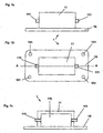
- a known sensor housing 1 with a housing body 11, a base plate 10 and recesses 111 for receiving connectors for the connection of, for example, signal lines is shown schematically in FIG Fig. 1 shown.
- An exact alignment of the sensor during assembly of the sensor housing 1 with the base plate 10 at a predetermined position is possible only with considerable adjustment and assembly costs, which is time-consuming and costly.
- the object of the present invention is therefore to provide an improved sensor housing for an inclinometer, which can be provided and mounted inexpensively, quickly and accurately.
- a sensor housing according to the invention for an inclinometer comprises, in particular, a housing body which is open at the bottom so that the housing interior downwardly exposed and with the housing body integrally formed feet, on each of which mounting holes for fixing the sensor housing are provided at a predetermined position.
- the sensor housing according to the invention also comprises on the underside of the housing and / or the feet three support projections for aligning the sensor housing at a predetermined support position.
- the feet are also designed to be particularly elastic, so that the fastening zones on the fastening bores of the feet are elastically connected to the housing body, which contains the sensor system.
- the feet are suitably formed as flat projections which extend in a plane with the underside of the housing body from the housing body by a predetermined amount in a predetermined direction, wherein on the housing body advantageously three or more Feet, each with a mounting hole and particularly advantageous four feet, each with a mounting hole are provided.
- the housing interior is cuboid and four feet are suitably arranged in the vicinity of the corners of the housing.
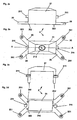
- An inventive sensor housing 2 of Fig. 2a, b, c and d advantageously comprises a housing body 21 with flat feet 20, which are formed as flat projections in a plane with the underside of the housing body 21 extending from the housing body 21 by a predetermined amount in a predetermined direction, provided on the flat feet 20 suitable holes 201 are, over which the sensor housing 2 can be fastened with suitable fastening means, such as screws at a predetermined position.
- suitable fastening means such as screws at a predetermined position.
- three support projections 202 for aligning the sensor housing 2 at a predetermined support position are provided on the underside of the housing body 21 and / or on the feet 20.
- a sensor housing 2 comprises a housing body 21, which is integrally formed with the feet 20, which in particular simplifies the manufacture and also the assembly of the sensor housing 2.
- a sensor housing 2 for providing a defined three-point support, also comprises at least three or more feet 20 with suitable bores 201, wherein in the embodiment of FIG Fig.2 .
- advantageously four feet 20 are provided, suitably close to the edges of the in the execution of Fig.2 advantageous cuboid housing body 21 are arranged.
- the feet 20 are also advantageously elastically formed so that they cooperate with the support projections 202 on the underside of the housing body 21 or the feet 20 to allow an accurate and secure alignment and mounting of the sensor, the sensors of voltages arising during mounting is decoupled. It will be understood that suitable attachment may be provided, for example, with a threaded fastener.
- a sensor housing 2 also comprises suitable recesses 211 for receiving plug connections for, for example, signal lines on the housing body 21 for connecting, for example, signal lines.
- the sensor housing 2 of the invention Fig. 2 is also advantageous and according to the invention open at the bottom, which can be arranged in a simple manner, a suitable sensor in the housing body 21 and subsequently sealed with a potting compound, which can be easily filled into the housing interior 210, whereby the formation of air pockets especially at critical points can be largely excluded, which also increases the resistance to rotation of arranged in the recesses 211 connectors and thus increases the reliability of the sensor.
- the top of the sensor housing 2 of the invention Fig.2 is also advantageously designed as a truncated tetrahedral pyramid, so that five are provided at an angle to each other arranged levels.
- the surface of the top of the housing body 21 is suitably provided with a relief-like structure 212, which is designed so that it remains recognizable after painting the housing body 21, wherein the relief-like structure 212 suitably a company logo and / or positioning marks which are respectively arranged on one or more of the five levels of the housing surface of the top of the housing body 21.
- the holes 201 on the feet 20 may be suitably provided with metal inserts for secure attachment and secure fit, which may be steel inserts in particular, resulting in an attachment by means such as screws and a corresponding tension when tightening the screws and elastic bending of the feet 20 due to the defined three-point support due to the support projections 202 of the invention increases the stabilization of the attachment and facilitates assembly.
- An inventive sensor housing 2 may be suitably made of metal or plastic.
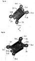
- FIG. 3a shows for a better understanding of the present invention, a schematic perspective view of the sensor housing of Fig. 2 from above and 3b a corresponding schematic perspective view of the sensor housing 2 of Fig. 2 from below, as well as already Fig. 2d can be taken from the housing interior 210 is suitably cuboid.
Landscapes
- Physics & Mathematics (AREA)
- General Physics & Mathematics (AREA)
- Engineering & Computer Science (AREA)
- Radar, Positioning & Navigation (AREA)
- Remote Sensing (AREA)
- Details Of Measuring And Other Instruments (AREA)
- Measuring Fluid Pressure (AREA)
- Casings For Electric Apparatus (AREA)
Description
Die vorliegende Erfindung bezieht sich auf ein Sensorgehäuse und insbesondere auf ein Sensorgehäuse für ein Inklinometer.The present invention relates to a sensor housing and more particularly to a sensor housing for an inclinometer.
Aus dem Stand der Technik sind Gehäuse 1 zur Aufnahme von Inklinometern bekannt, die zur Anordnung an einer vorbestimmten Position eine Grundplatte 10 mit Befestigungsbohrungen 101 umfassen. Ein derartiges bekanntes Sensorgehäuse 1 mit einem Gehäusekörper 11, einer Grundplatte 10 und mit Ausnehmungen 111 zur Aufnahme von Steckverbindungen für den Anschluß von beispielsweise Signalleitungen ist schematisch in
Aufgabe der vorliegenden Erfindung ist daher, ein verbessertes Sensorgehäuse für ein Inklinometer bereitzustellen, das kostengünstig, zeitsparend und exakt bereitgestellt und montiert werden kann.The object of the present invention is therefore to provide an improved sensor housing for an inclinometer, which can be provided and mounted inexpensively, quickly and accurately.
Die Aufgabe der vorliegenden Erfindung wird mit den Merkmalen des unabhängigen Anspruchs 1 gelöst. Vorteilhafte Ausführungen der vorliegenden Erfindung werden mit den Merkmalen der abhängigen Ansprüche erzielt und/oder in der nachfolgenden Beschreibung erwähnt.The object of the present invention is achieved with the features of independent claim 1. Advantageous embodiments of the present invention are achieved with the features of the dependent claims and / or mentioned in the following description.
Ein erfindungsgemäßes Sensorgehäuse für ein Inklinometer umfasst insbesondere einen Gehäusekörper, der nach unten offen ist, so dass der Gehäuseinnenraum nach unten frei liegt und mit dem Gehäusekörper einstückig ausgebildete Füße, an denen jeweils Befestigungsbohrungen zur Befestigung des Sensorgehäuses an einer vorbestimmten Position vorgesehen sind. umfasst das Erfindungsgemäß Sensorgehäuse außerdem an der Unterseite des Gehäuses und/oder der Füße drei Auflagevorsprünge zur Ausrichtung des Sensorgehäuses an einer vorbestimmten Auflageposition. Durch die erfindungsgemäßen drei Auflagevorsprünge wird eine definierte Drei-Punkt-Auflage unabhängig der Anzahl von Befestigungen an den Befestigungsbohrungen der Füße, die die Anzahl der drei Auflagevorsprünge vorteilhaft übersteigen können, bereitgestellt.A sensor housing according to the invention for an inclinometer comprises, in particular, a housing body which is open at the bottom so that the housing interior downwardly exposed and with the housing body integrally formed feet, on each of which mounting holes for fixing the sensor housing are provided at a predetermined position. The sensor housing according to the invention also comprises on the underside of the housing and / or the feet three support projections for aligning the sensor housing at a predetermined support position. By means of the three support projections according to the invention, a defined three-point support is provided, irrespective of the number of fastenings on the fastening bores of the feet, which can advantageously exceed the number of the three support projections.
Besonders vorteilhaft sind bei einem erfindungsgemäßen Sensorgehäuse außerdem die Füße elastisch ausgebildet, so dass die Befestigungszonen an den Befestigungsbohrungen der Füße elastisch mit dem Gehäusekörper verbunden sind, der die Sensorik beinhaltet. Hierdurch ist eine exakte Ausrichtung des Sensorgehäuses und des Sensors insbesondere durch die definierte Drei-Punkt-Auflage und die Entkopplung der Sensorik von bei der Befestigung auftretenden Spannungen möglich.In addition, in a sensor housing according to the invention, the feet are also designed to be particularly elastic, so that the fastening zones on the fastening bores of the feet are elastically connected to the housing body, which contains the sensor system. As a result, an exact alignment of the sensor housing and the sensor is possible in particular by the defined three-point support and the decoupling of the sensor from voltages occurring during mounting.
Nach einer weiteren vorteilhaften Ausführung der vorliegenden Erfindung sind die Füße geeigneter Weise als flache Vorsprünge ausgebildet, die sich in einer Ebene mit der Unterseite des Gehäusekörpers von dem Gehäusekörper ausgehend um einen vorbestimmten Betrag in eine vorbestimmte Richtung erstrecken, wobei an dem Gehäusekörper vorteilhaft drei oder mehr Füße mit jeweils einer Befestigungsbohrung und besonders vorteilhaft vier Füße mit jeweils einer Befestigungsbohrung vorgesehen sind.According to a further advantageous embodiment of the present invention, the feet are suitably formed as flat projections which extend in a plane with the underside of the housing body from the housing body by a predetermined amount in a predetermined direction, wherein on the housing body advantageously three or more Feet, each with a mounting hole and particularly advantageous four feet, each with a mounting hole are provided.
Geeigneter Weise ist hierbei insbesondere der Gehäuseinnenraum quaderförmig ausgebildet und sind geeigneter Weise vier Füße in der Umgebung der Ecken des Gehäuses angeordnet.Suitably, in this case, in particular, the housing interior is cuboid and four feet are suitably arranged in the vicinity of the corners of the housing.
Die vorliegende Erfindung wird nachfolgend ohne jede Beschränkung anhand von vorteilhaften Ausführungen beschrieben, wobei die Beschreibung von schematischen Zeichnungen begleitet ist. Hierzu zeigt:
-
Fig. 1a eine Seitenansicht eines herkömmlichen Sensorgehäuses,Fig. 1b eine Draufsicht auf das Sensorgehäuse vonFig. 1a und Fig. 1c einen Schnitt durch das Sensorgehäuse vonFig. 1a und 1b entlang der Linie A-A vonFig. 1b ; -
Fig. 2a eine Seitenansicht eines erfindungsgemäßen Sensorgehäuses,Fig. 2b eine Draufsicht auf das erfindungsgemäße Sensorgehäuse vonFig. 2a, Fig. 2c einen Schnitt durch das Sensorgehäuse vonFig. 2a und 2b entlang der Linie A-A vonFig. 2b und Fig. 2d das Sensorgehäuse vonFig. 2a, 2b und 2c von unten; -
Fig. 3a eine perspektivische Darstellung des Sensorgehäuses vonFig. 2 von oben undFig. 3b eine perspektivische Darstellung des Sensorgehäuses vonFig. 2 von unten.
-
Fig. 1a a side view of a conventional sensor housing,Fig. 1b a plan view of the sensor housing ofFig. 1a and Fig. 1c a section through the sensor housing ofFig. 1a and 1b along the line AA ofFig. 1b ; -
Fig. 2a a side view of a sensor housing according to the invention,Fig. 2b a plan view of the sensor housing according to the invention ofFig. 2a, Fig. 2c a section through the sensor housing ofFig. 2a and 2b along the line AA ofFig. 2b and Fig. 2d the sensor housing ofFig. 2a, 2b and 2c from underneath; -
Fig. 3a a perspective view of the sensor housing ofFig. 2 from above andFig. 3b a perspective view of the sensor housing ofFig. 2 from underneath.
Ein erfindungsgemäßes Sensorgehäuse 2 von
Vorteilhaft umfasst ein erfindungsgemäßes Sensorgehäuse 2 einen Gehäusekörper 21, der mit den Füßen 20 einstückig ausgebildet ist, was insbesondere die Herstellung und auch die Montage des Sensorgehäuses 2 vereinfacht.Advantageously, a
Für eine Bereitstellung einer definierten Drei-Punkt-Auflage umfasst ein erfindungsgemäßes Sensorgehäuse 2 außerdem wenigstens drei oder mehr Füße 20 mit geeigneten Bohrungen 201, wobei bei der Ausführung von
Die Füße 20 sind außerdem vorteilhaft elastisch ausgebildet, so daß sie mit den Auflagevorsprüngen 202 an der Unterseite des Gehäusekörpers 21 oder der Füße 20 zusammenwirken, um eine exakte und sichere Ausrichtung und Befestigung des Sensors zu ermöglichen, wobei die Sensorik von bei der Befestigung entstehenden Spannungen entkoppelt ist. Es ist klar, daß eine geeignete Befestigung beispielsweise mit einer Schraubbefestigung bereitgestellt werden kann.The
Es ist außerdem klar, dass ein erfindungsgemäßes Sensorgehäuse 2 außerdem geeignete Ausnehmungen 211 zur Aufnahme von Steckverbindungen für beispielsweise Signalleitungen an dem Gehäusekörper 21 zur Verbindung von beispielsweise Signalleitungen umfasst.It is also clear that a
Das erfindungsgemäße Sensorgehäuse 2 von
Die Oberseite des erfindungsgemäßen Sensorgehäuses 2 von
Die Bohrungen 201 an den Füßen 20 können für eine sichere Befestigung und einen sicheren Halt geeigneter Weise mit Metalleinsätzen versehen sein, die insbesondere Stahleinsätze sein können, was bei einer Befestigung mittels beispielsweise Schrauben und einer entsprechenden Spannung beim Anziehen der Schrauben und beim elastischen Verbiegen der Füße 20 aufgrund der definierten Drei-Punkt-Auflage aufgrund der erfindungsgemäßen Auflagevorsprünge 202 die Stabilisierung der Befestigung erhöht und die Montage erleichtert.The
Ein erfindungsgemäßes Sensorgehäuse 2 kann geeigneter Weise aus Metall oder Kunststoff bereitgestellt sein.An
Auf die nach unten freiliegende Oberfläche der Vergußmasse in dem Gehäuseinnenraum 210, in der die Sensorik eingebettet ist, kann geeigneter Weise und vorteilhaft ein Typenschild aufgeklebt sein.On the downwardly exposed surface of the potting compound in the
- Sensorgehäusesensor housing
- 11
- Grundplattebaseplate
- 1010
- Befestigungsbohrungmounting hole
- 101101
- Gehäusekörperhousing body
- 1111
- GehäuseinnenraumHousing interior
- 110110
- Ausnehmungrecess
- 111111
- Sensorgehäusesensor housing
- 22
- Fußfoot
- 2020
- Befestigungsbohrungmounting hole
- 201201
- Auflagevorsprungbearing protrusion
- 202202
- Gehäusekörperhousing body
- 2121
- GehäuseinnenraumHousing interior
- 210210
- Ausnehmungrecess
- 211211
- Reliefartige StrukturRelief-like structure
- 212212
Claims (13)
- Sensor casing (2) for an inclinometer comprising a casing body (21) which is open at the bottom, so that the casing interior (210) is exposed at the bottom, and comprising feet (20) integral with the casing (21), one respective fastening bore (201) being provided on said feet for fastening the sensor casing (2) in a predetermined position, wherein three bearing projections (202) are provided on the underside of the casing body (21) and/or the feet (20) for aligning the sensor casing (2) in a predetermined bearing position.
- Sensor casing (2) according to Claim 1 wherein annular metal inserts are provided in the fastening bores (201) for reinforcing and securing the fastening.
- Sensor casing (2) according to one of the preceding Claims 1 or 2 wherein the feet (20) are of resilient configuration.
- Sensor casing (2) according to one of the preceding Claims 1 to 3 wherein the feet (20) are configured as planar projections which, starting from the casing body (21), extend by a predetermined amount in a predetermined direction in a plane with the underside of the casing body (21).
- Sensor casing (2) according to one of the preceding Claims 1 to 4 wherein four feet (20) are provided on the casing body (21).
- Sensor casing (2) according to one of the preceding Claims 1 to 5 wherein the casing body (21) is of cuboidal configuration and the feet (20) are arranged in the vicinity of the corners of the casing body (21).
- Sensor casing (2) according to one of the preceding Claims 1 to 6 wherein the upper face of the casing body (21) comprises a relief-type structure (212) which is configured such that it remains visible after painting the casing body (21).
- Sensor casing (2) according to Claim 7 wherein the relief-type structure (212) comprises a company logo and/or positional markings.
- Sensor casing (2) according to one of Claims 1 to 8 wherein the upper face of the casing body (21) is configured as a flattened pyramid.
- Sensor casing (2) according to one of Claims 1 to 9 wherein the casing interior (210) is of cuboidal configuration.
- Sensor casing (2) according to one of Claims 1 to 10 wherein the casing body (21) together with the feet (20) consist of metal or plastics material.
- Sensor casing (2) according to one of Claims 1 to 11 comprising an inclinometer which is arranged in the casing body (21) and which is inserted from below into the casing interior (210) and is embedded in sealing compound.
- Sensor casing (2) according to Claim 12 comprising a label adhesively bonded to the surface of the sealing compound which is exposed at the bottom.
Applications Claiming Priority (1)
| Application Number | Priority Date | Filing Date | Title |
|---|---|---|---|
| DE200820007291 DE202008007291U1 (en) | 2008-05-30 | 2008-05-30 | sensor housing |
Publications (2)
| Publication Number | Publication Date |
|---|---|
| EP2128564A1 EP2128564A1 (en) | 2009-12-02 |
| EP2128564B1 true EP2128564B1 (en) | 2012-12-19 |
Family
ID=39736681
Family Applications (1)
| Application Number | Title | Priority Date | Filing Date |
|---|---|---|---|
| EP20090100281 Active EP2128564B1 (en) | 2008-05-30 | 2009-05-14 | Sensor casing |
Country Status (2)
| Country | Link |
|---|---|
| EP (1) | EP2128564B1 (en) |
| DE (1) | DE202008007291U1 (en) |
Families Citing this family (3)
| Publication number | Priority date | Publication date | Assignee | Title |
|---|---|---|---|---|
| GB2558882A (en) * | 2017-01-11 | 2018-07-25 | Christopher Round Martin | Tool and method for crankshaft angle calculation |
| JP2019023606A (en) * | 2017-07-24 | 2019-02-14 | 株式会社デンソー | Physical quantity measuring device and method of manufacturing physical quantity measuring device |
| CN113564430B (en) * | 2021-09-24 | 2021-11-26 | 惠州市华阳精机有限公司 | Sensor housing, die-casting die and die-casting process thereof |
Family Cites Families (2)
| Publication number | Priority date | Publication date | Assignee | Title |
|---|---|---|---|---|
| US3952142A (en) * | 1974-08-09 | 1976-04-20 | Polycase, Inc. | Electronic enclosure |
| US4949467A (en) * | 1988-10-03 | 1990-08-21 | Robert Oman | Inclinometer including an apparatus for maintaining a scientific and measuring instrument or the like in a level plane |
-
2008
- 2008-05-30 DE DE200820007291 patent/DE202008007291U1/en not_active Expired - Lifetime
-
2009
- 2009-05-14 EP EP20090100281 patent/EP2128564B1/en active Active
Also Published As
| Publication number | Publication date |
|---|---|
| EP2128564A1 (en) | 2009-12-02 |
| DE202008007291U1 (en) | 2008-09-04 |
Similar Documents
| Publication | Publication Date | Title |
|---|---|---|
| EP2128564B1 (en) | Sensor casing | |
| DE9202995U1 (en) | Flat key | |
| EP3058846A1 (en) | Side plate for drawer with insertable panel | |
| DE102010005485A1 (en) | support part | |
| EP3370044A1 (en) | Weighing cell for a weighing device | |
| DE19738803B4 (en) | Housing for a device, in particular sensor for motor vehicles | |
| EP2664724B1 (en) | Connection assembly with an intermediate element | |
| WO2011116939A1 (en) | Fastening plate for a door closer and door-closing device with a fastening plate of this type | |
| DE202010000965U1 (en) | Device for fastening preferably sandwich panels | |
| EP2181571B1 (en) | Installation cabinet and method for producing a place for an installation cabinet | |
| EP0939175A2 (en) | Connecting element for assembling wood and concrete | |
| DE202017104271U1 (en) | Floor element for inductive charging | |
| DE102007038737B4 (en) | Base plate for a sensor assembly, support body for fastening the sensor assembly, sensor assembly and fastening system | |
| DE202010006108U1 (en) | Shock-absorbing protection device | |
| DE102008001268A1 (en) | Plug arrangement in a machine tool, in particular in a hand tool | |
| DE102006032024B3 (en) | Electronic control device for automatic transmission in automobile range, has hydraulic plate, electrical carrier component, and radiator box | |
| DE202008005705U1 (en) | Torque wrench with digital display | |
| DE202007015546U1 (en) | survey point | |
| EP3070440B1 (en) | Sensor casing | |
| DE202015102910U1 (en) | Fixing and adjusting device for fixing and / or alignment of angular elements of insulation boards | |
| DE202008016759U1 (en) | An element | |
| WO2019053044A1 (en) | DEVICE FOR INSERTING A TRANSPONDANT | |
| EP1440827B1 (en) | Micro-motor mounting system | |
| DE202014102754U1 (en) | Holder for an electronic device in motor vehicles | |
| DE29802438U1 (en) | Manhole cover |
Legal Events
| Date | Code | Title | Description |
|---|---|---|---|
| PUAI | Public reference made under article 153(3) epc to a published international application that has entered the european phase |
Free format text: ORIGINAL CODE: 0009012 |
|
| 17P | Request for examination filed |
Effective date: 20090610 |
|
| AK | Designated contracting states |
Kind code of ref document: A1 Designated state(s): AT BE BG CH CY CZ DE DK EE ES FI FR GB GR HR HU IE IS IT LI LT LU LV MC MK MT NL NO PL PT RO SE SI SK TR |
|
| RIC1 | Information provided on ipc code assigned before grant |
Ipc: G01D 11/24 20060101ALI20120625BHEP Ipc: G01C 9/28 20060101AFI20120625BHEP |
|
| GRAP | Despatch of communication of intention to grant a patent |
Free format text: ORIGINAL CODE: EPIDOSNIGR1 |
|
| GRAS | Grant fee paid |
Free format text: ORIGINAL CODE: EPIDOSNIGR3 |
|
| GRAA | (expected) grant |
Free format text: ORIGINAL CODE: 0009210 |
|
| AK | Designated contracting states |
Kind code of ref document: B1 Designated state(s): AT BE BG CH CY CZ DE DK EE ES FI FR GB GR HR HU IE IS IT LI LT LU LV MC MK MT NL NO PL PT RO SE SI SK TR |
|
| REG | Reference to a national code |
Ref country code: GB Ref legal event code: FG4D Free format text: NOT ENGLISH |
|
| REG | Reference to a national code |
Ref country code: CH Ref legal event code: EP |
|
| REG | Reference to a national code |
Ref country code: AT Ref legal event code: REF Ref document number: 589621 Country of ref document: AT Kind code of ref document: T Effective date: 20130115 |
|
| REG | Reference to a national code |
Ref country code: DE Ref legal event code: R096 Ref document number: 502009005722 Country of ref document: DE Effective date: 20130221 |
|
| REG | Reference to a national code |
Ref country code: DE Ref legal event code: R082 Ref document number: 502009005722 Country of ref document: DE Representative=s name: STIPPL PATENTANWAELTE, DE |
|
| REG | Reference to a national code |
Ref country code: DE Ref legal event code: R082 Ref document number: 502009005722 Country of ref document: DE Representative=s name: STIPPL PATENTANWAELTE, DE |
|
| PG25 | Lapsed in a contracting state [announced via postgrant information from national office to epo] |
Ref country code: FI Free format text: LAPSE BECAUSE OF FAILURE TO SUBMIT A TRANSLATION OF THE DESCRIPTION OR TO PAY THE FEE WITHIN THE PRESCRIBED TIME-LIMIT Effective date: 20121219 Ref country code: ES Free format text: LAPSE BECAUSE OF FAILURE TO SUBMIT A TRANSLATION OF THE DESCRIPTION OR TO PAY THE FEE WITHIN THE PRESCRIBED TIME-LIMIT Effective date: 20130330 Ref country code: HR Free format text: LAPSE BECAUSE OF FAILURE TO SUBMIT A TRANSLATION OF THE DESCRIPTION OR TO PAY THE FEE WITHIN THE PRESCRIBED TIME-LIMIT Effective date: 20121219 Ref country code: LT Free format text: LAPSE BECAUSE OF FAILURE TO SUBMIT A TRANSLATION OF THE DESCRIPTION OR TO PAY THE FEE WITHIN THE PRESCRIBED TIME-LIMIT Effective date: 20121219 Ref country code: SE Free format text: LAPSE BECAUSE OF FAILURE TO SUBMIT A TRANSLATION OF THE DESCRIPTION OR TO PAY THE FEE WITHIN THE PRESCRIBED TIME-LIMIT Effective date: 20121219 Ref country code: NO Free format text: LAPSE BECAUSE OF FAILURE TO SUBMIT A TRANSLATION OF THE DESCRIPTION OR TO PAY THE FEE WITHIN THE PRESCRIBED TIME-LIMIT Effective date: 20130319 |
|
| REG | Reference to a national code |
Ref country code: NL Ref legal event code: VDEP Effective date: 20121219 |
|
| REG | Reference to a national code |
Ref country code: LT Ref legal event code: MG4D |
|
| PG25 | Lapsed in a contracting state [announced via postgrant information from national office to epo] |
Ref country code: GR Free format text: LAPSE BECAUSE OF FAILURE TO SUBMIT A TRANSLATION OF THE DESCRIPTION OR TO PAY THE FEE WITHIN THE PRESCRIBED TIME-LIMIT Effective date: 20130320 Ref country code: SI Free format text: LAPSE BECAUSE OF FAILURE TO SUBMIT A TRANSLATION OF THE DESCRIPTION OR TO PAY THE FEE WITHIN THE PRESCRIBED TIME-LIMIT Effective date: 20121219 Ref country code: LV Free format text: LAPSE BECAUSE OF FAILURE TO SUBMIT A TRANSLATION OF THE DESCRIPTION OR TO PAY THE FEE WITHIN THE PRESCRIBED TIME-LIMIT Effective date: 20121219 |
|
| PG25 | Lapsed in a contracting state [announced via postgrant information from national office to epo] |
Ref country code: CZ Free format text: LAPSE BECAUSE OF FAILURE TO SUBMIT A TRANSLATION OF THE DESCRIPTION OR TO PAY THE FEE WITHIN THE PRESCRIBED TIME-LIMIT Effective date: 20121219 Ref country code: BG Free format text: LAPSE BECAUSE OF FAILURE TO SUBMIT A TRANSLATION OF THE DESCRIPTION OR TO PAY THE FEE WITHIN THE PRESCRIBED TIME-LIMIT Effective date: 20130319 Ref country code: IS Free format text: LAPSE BECAUSE OF FAILURE TO SUBMIT A TRANSLATION OF THE DESCRIPTION OR TO PAY THE FEE WITHIN THE PRESCRIBED TIME-LIMIT Effective date: 20130419 Ref country code: SK Free format text: LAPSE BECAUSE OF FAILURE TO SUBMIT A TRANSLATION OF THE DESCRIPTION OR TO PAY THE FEE WITHIN THE PRESCRIBED TIME-LIMIT Effective date: 20121219 Ref country code: EE Free format text: LAPSE BECAUSE OF FAILURE TO SUBMIT A TRANSLATION OF THE DESCRIPTION OR TO PAY THE FEE WITHIN THE PRESCRIBED TIME-LIMIT Effective date: 20121219 |
|
| PG25 | Lapsed in a contracting state [announced via postgrant information from national office to epo] |
Ref country code: PT Free format text: LAPSE BECAUSE OF FAILURE TO SUBMIT A TRANSLATION OF THE DESCRIPTION OR TO PAY THE FEE WITHIN THE PRESCRIBED TIME-LIMIT Effective date: 20130419 Ref country code: PL Free format text: LAPSE BECAUSE OF FAILURE TO SUBMIT A TRANSLATION OF THE DESCRIPTION OR TO PAY THE FEE WITHIN THE PRESCRIBED TIME-LIMIT Effective date: 20121219 Ref country code: RO Free format text: LAPSE BECAUSE OF FAILURE TO SUBMIT A TRANSLATION OF THE DESCRIPTION OR TO PAY THE FEE WITHIN THE PRESCRIBED TIME-LIMIT Effective date: 20121219 Ref country code: NL Free format text: LAPSE BECAUSE OF FAILURE TO SUBMIT A TRANSLATION OF THE DESCRIPTION OR TO PAY THE FEE WITHIN THE PRESCRIBED TIME-LIMIT Effective date: 20121219 |
|
| PLBE | No opposition filed within time limit |
Free format text: ORIGINAL CODE: 0009261 |
|
| STAA | Information on the status of an ep patent application or granted ep patent |
Free format text: STATUS: NO OPPOSITION FILED WITHIN TIME LIMIT |
|
| PG25 | Lapsed in a contracting state [announced via postgrant information from national office to epo] |
Ref country code: DK Free format text: LAPSE BECAUSE OF FAILURE TO SUBMIT A TRANSLATION OF THE DESCRIPTION OR TO PAY THE FEE WITHIN THE PRESCRIBED TIME-LIMIT Effective date: 20121219 |
|
| 26N | No opposition filed |
Effective date: 20130920 |
|
| PG25 | Lapsed in a contracting state [announced via postgrant information from national office to epo] |
Ref country code: CY Free format text: LAPSE BECAUSE OF FAILURE TO SUBMIT A TRANSLATION OF THE DESCRIPTION OR TO PAY THE FEE WITHIN THE PRESCRIBED TIME-LIMIT Effective date: 20121219 |
|
| BERE | Be: lapsed |
Owner name: INTER CONTROL HERMANN KOHLER G.M.B.H. & CO. KG Effective date: 20130531 |
|
| PG25 | Lapsed in a contracting state [announced via postgrant information from national office to epo] |
Ref country code: MC Free format text: LAPSE BECAUSE OF FAILURE TO SUBMIT A TRANSLATION OF THE DESCRIPTION OR TO PAY THE FEE WITHIN THE PRESCRIBED TIME-LIMIT Effective date: 20121219 |
|
| REG | Reference to a national code |
Ref country code: CH Ref legal event code: PL |
|
| REG | Reference to a national code |
Ref country code: DE Ref legal event code: R097 Ref document number: 502009005722 Country of ref document: DE Effective date: 20130920 |
|
| PG25 | Lapsed in a contracting state [announced via postgrant information from national office to epo] |
Ref country code: CH Free format text: LAPSE BECAUSE OF NON-PAYMENT OF DUE FEES Effective date: 20130531 Ref country code: LI Free format text: LAPSE BECAUSE OF NON-PAYMENT OF DUE FEES Effective date: 20130531 |
|
| REG | Reference to a national code |
Ref country code: IE Ref legal event code: MM4A |
|
| PG25 | Lapsed in a contracting state [announced via postgrant information from national office to epo] |
Ref country code: BE Free format text: LAPSE BECAUSE OF NON-PAYMENT OF DUE FEES Effective date: 20130531 |
|
| PG25 | Lapsed in a contracting state [announced via postgrant information from national office to epo] |
Ref country code: IE Free format text: LAPSE BECAUSE OF NON-PAYMENT OF DUE FEES Effective date: 20130514 |
|
| PG25 | Lapsed in a contracting state [announced via postgrant information from national office to epo] |
Ref country code: MT Free format text: LAPSE BECAUSE OF FAILURE TO SUBMIT A TRANSLATION OF THE DESCRIPTION OR TO PAY THE FEE WITHIN THE PRESCRIBED TIME-LIMIT Effective date: 20121219 |
|
| PG25 | Lapsed in a contracting state [announced via postgrant information from national office to epo] |
Ref country code: TR Free format text: LAPSE BECAUSE OF FAILURE TO SUBMIT A TRANSLATION OF THE DESCRIPTION OR TO PAY THE FEE WITHIN THE PRESCRIBED TIME-LIMIT Effective date: 20121219 |
|
| REG | Reference to a national code |
Ref country code: AT Ref legal event code: MM01 Ref document number: 589621 Country of ref document: AT Kind code of ref document: T Effective date: 20140514 |
|
| PG25 | Lapsed in a contracting state [announced via postgrant information from national office to epo] |
Ref country code: LU Free format text: LAPSE BECAUSE OF NON-PAYMENT OF DUE FEES Effective date: 20130514 Ref country code: MK Free format text: LAPSE BECAUSE OF FAILURE TO SUBMIT A TRANSLATION OF THE DESCRIPTION OR TO PAY THE FEE WITHIN THE PRESCRIBED TIME-LIMIT Effective date: 20121219 Ref country code: HU Free format text: LAPSE BECAUSE OF FAILURE TO SUBMIT A TRANSLATION OF THE DESCRIPTION OR TO PAY THE FEE WITHIN THE PRESCRIBED TIME-LIMIT; INVALID AB INITIO Effective date: 20090514 |
|
| PGFP | Annual fee paid to national office [announced via postgrant information from national office to epo] |
Ref country code: GB Payment date: 20150521 Year of fee payment: 7 |
|
| PG25 | Lapsed in a contracting state [announced via postgrant information from national office to epo] |
Ref country code: AT Free format text: LAPSE BECAUSE OF NON-PAYMENT OF DUE FEES Effective date: 20140514 |
|
| REG | Reference to a national code |
Ref country code: FR Ref legal event code: PLFP Year of fee payment: 8 |
|
| GBPC | Gb: european patent ceased through non-payment of renewal fee |
Effective date: 20160514 |
|
| REG | Reference to a national code |
Ref country code: FR Ref legal event code: PLFP Year of fee payment: 9 |
|
| PG25 | Lapsed in a contracting state [announced via postgrant information from national office to epo] |
Ref country code: GB Free format text: LAPSE BECAUSE OF NON-PAYMENT OF DUE FEES Effective date: 20160514 |
|
| REG | Reference to a national code |
Ref country code: FR Ref legal event code: PLFP Year of fee payment: 10 |
|
| P01 | Opt-out of the competence of the unified patent court (upc) registered |
Effective date: 20230508 |
|
| PGFP | Annual fee paid to national office [announced via postgrant information from national office to epo] |
Ref country code: FR Payment date: 20230517 Year of fee payment: 15 |
|
| REG | Reference to a national code |
Ref country code: DE Ref legal event code: R082 Ref document number: 502009005722 Country of ref document: DE Representative=s name: 4IP GLEIMPETRI PATENT- UND RECHTSANWALTSPARTNE, DE |
|
| PG25 | Lapsed in a contracting state [announced via postgrant information from national office to epo] |
Ref country code: FR Free format text: LAPSE BECAUSE OF NON-PAYMENT OF DUE FEES Effective date: 20240531 |
|
| PGFP | Annual fee paid to national office [announced via postgrant information from national office to epo] |
Ref country code: DE Payment date: 20250212 Year of fee payment: 17 |
|
| PGFP | Annual fee paid to national office [announced via postgrant information from national office to epo] |
Ref country code: IT Payment date: 20250530 Year of fee payment: 17 |