EP2128452B1 - Jet pump for production of compressed air foam - Google Patents
Jet pump for production of compressed air foam Download PDFInfo
- Publication number
- EP2128452B1 EP2128452B1 EP20090006154 EP09006154A EP2128452B1 EP 2128452 B1 EP2128452 B1 EP 2128452B1 EP 20090006154 EP20090006154 EP 20090006154 EP 09006154 A EP09006154 A EP 09006154A EP 2128452 B1 EP2128452 B1 EP 2128452B1
- Authority
- EP
- European Patent Office
- Prior art keywords
- jet pump
- water
- jet
- nozzles
- pump according
- Prior art date
- Legal status (The legal status is an assumption and is not a legal conclusion. Google has not performed a legal analysis and makes no representation as to the accuracy of the status listed.)
- Not-in-force
Links
Images


Classifications
-
- A—HUMAN NECESSITIES
- A62—LIFE-SAVING; FIRE-FIGHTING
- A62C—FIRE-FIGHTING
- A62C17/00—Hand fire-extinguishers essentially in the form of pistols or rifles
-
- A—HUMAN NECESSITIES
- A62—LIFE-SAVING; FIRE-FIGHTING
- A62C—FIRE-FIGHTING
- A62C31/00—Delivery of fire-extinguishing material
- A62C31/02—Nozzles specially adapted for fire-extinguishing
- A62C31/03—Nozzles specially adapted for fire-extinguishing adjustable, e.g. from spray to jet or vice versa
-
- A—HUMAN NECESSITIES
- A62—LIFE-SAVING; FIRE-FIGHTING
- A62C—FIRE-FIGHTING
- A62C31/00—Delivery of fire-extinguishing material
- A62C31/02—Nozzles specially adapted for fire-extinguishing
- A62C31/12—Nozzles specially adapted for fire-extinguishing for delivering foam or atomised foam
-
- F—MECHANICAL ENGINEERING; LIGHTING; HEATING; WEAPONS; BLASTING
- F04—POSITIVE - DISPLACEMENT MACHINES FOR LIQUIDS; PUMPS FOR LIQUIDS OR ELASTIC FLUIDS
- F04F—PUMPING OF FLUID BY DIRECT CONTACT OF ANOTHER FLUID OR BY USING INERTIA OF FLUID TO BE PUMPED; SIPHONS
- F04F5/00—Jet pumps, i.e. devices in which flow is induced by pressure drop caused by velocity of another fluid flow
- F04F5/02—Jet pumps, i.e. devices in which flow is induced by pressure drop caused by velocity of another fluid flow the inducing fluid being liquid
- F04F5/04—Jet pumps, i.e. devices in which flow is induced by pressure drop caused by velocity of another fluid flow the inducing fluid being liquid displacing elastic fluids
-
- F—MECHANICAL ENGINEERING; LIGHTING; HEATING; WEAPONS; BLASTING
- F04—POSITIVE - DISPLACEMENT MACHINES FOR LIQUIDS; PUMPS FOR LIQUIDS OR ELASTIC FLUIDS
- F04F—PUMPING OF FLUID BY DIRECT CONTACT OF ANOTHER FLUID OR BY USING INERTIA OF FLUID TO BE PUMPED; SIPHONS
- F04F5/00—Jet pumps, i.e. devices in which flow is induced by pressure drop caused by velocity of another fluid flow
- F04F5/44—Component parts, details, or accessories not provided for in, or of interest apart from, groups F04F5/02 - F04F5/42
- F04F5/46—Arrangements of nozzles
- F04F5/461—Adjustable nozzles
-
- F—MECHANICAL ENGINEERING; LIGHTING; HEATING; WEAPONS; BLASTING
- F04—POSITIVE - DISPLACEMENT MACHINES FOR LIQUIDS; PUMPS FOR LIQUIDS OR ELASTIC FLUIDS
- F04F—PUMPING OF FLUID BY DIRECT CONTACT OF ANOTHER FLUID OR BY USING INERTIA OF FLUID TO BE PUMPED; SIPHONS
- F04F5/00—Jet pumps, i.e. devices in which flow is induced by pressure drop caused by velocity of another fluid flow
- F04F5/44—Component parts, details, or accessories not provided for in, or of interest apart from, groups F04F5/02 - F04F5/42
- F04F5/46—Arrangements of nozzles
- F04F5/463—Arrangements of nozzles with provisions for mixing
-
- F—MECHANICAL ENGINEERING; LIGHTING; HEATING; WEAPONS; BLASTING
- F04—POSITIVE - DISPLACEMENT MACHINES FOR LIQUIDS; PUMPS FOR LIQUIDS OR ELASTIC FLUIDS
- F04F—PUMPING OF FLUID BY DIRECT CONTACT OF ANOTHER FLUID OR BY USING INERTIA OF FLUID TO BE PUMPED; SIPHONS
- F04F5/00—Jet pumps, i.e. devices in which flow is induced by pressure drop caused by velocity of another fluid flow
- F04F5/44—Component parts, details, or accessories not provided for in, or of interest apart from, groups F04F5/02 - F04F5/42
- F04F5/46—Arrangements of nozzles
- F04F5/466—Arrangements of nozzles with a plurality of nozzles arranged in parallel
Definitions
- the invention relates to a jet pump, in particular for admixing air to a water, water / foaming agent, wetting agent mixture jet or the like, having a water inlet, an outlet for the water-air mixture and a suction space arranged between inlet and outlet with a Heated nozzle, a catching nozzle and an air inlet.
- jet pumps are known and can be used as simple pumps for sucking, aspirating or admixing gases or liquids to a flowing liquid.
- a jet pump can be operated, for example, with water.
- the water passes through a motive nozzle into the suction chamber. Due to the flow velocity of the water within the motive nozzle, a free water jet is created within the suction space at the mouth of the motive nozzle. Due to the jet velocity, the air present in the suction space is entrained and admixed with the jet, so that a vacuum is created in the suction space arises, which causes a renewed air intake through an air inlet opening.
- the water jet arrives at the other end of the mixing chamber in a catching nozzle and from there to the outlet of the jet pump.
- such jet pumps can only absorb a small amount of air, which is why they are not suitable if as much air as possible is to be admixed and, in particular, not if back pressure exists at the outlet.
- a corresponding apparatus for producing an air foam is in the US 2,577,451 (Standard Oil Development Company).
- the apparatus allows the transport of air foam over a considerable distance under pressure. It includes a plurality of jet pumps which suck air into a liquid foaming agent jet. These jet pumps are connected in parallel and are located between a liquid foam center pipe and a foam pipe.
- Each of the jet pumps comprises a cylindrical nozzle with a cylindrical inner part.
- Each of the cylindrical nozzles is arranged downstream of a mixing tube, wherein there are air nozzles between the cylindrical nozzles and the mixing tubes.
- the object of the invention is therefore to provide a jet pump for admixing gas in a water, water / Schaumffen- or wetting agent mixture beam that mix a larger amount of gas in the trap nozzle foam, compress them in the compression space and can be used universally.
- the traffic cones have slots which are inclined relative to a longitudinal axis.
- the jet pump according to the invention has at least two parallel drive nozzles, which are traversed by the water.
- the individual motive nozzles are designed correspondingly smaller than a single motive nozzle. Due to the smaller diameter of the motive nozzles creates a greater flow velocity of the water within the motive nozzles. As the water emerges from the motive nozzles into the common mixing chamber, the resulting jet of water has a greater velocity immediately more air is sucked in.
- the traffic cone in front of the inlet openings of the driving nozzles there is a turbulence of the water flow, which is thereby converted from an initial laminar into a turbulent flow.
- the inclined slots of the traffic cones generate a twist and thus an even greater turbulence.
- this creates a jet consisting of a large amount of small droplets, which have a large surface area and thus entrain more air.
- the sucked in the mixing chamber air is thereby better mixed with the water, water / foaming agent or wetting agent mixture jet.
- the water jet passes to the suction chamber in the collecting nozzles, which are also designed separately for each jet of water.
- the inlet openings of the collecting nozzles on the mixing chamber are typically larger than the mouth openings of the driving nozzles. This ensures that the air-enriched water, water / foaming agent or wetting agent mixture jet passes completely into the respective catching nozzle.
- the large turbulence creates a homogeneous, fine-bubble extinguishing foam in the catching nozzle.
- the catch nozzles open at the end of the jet pump in a common compression space.
- the transition between catch mouth and compression space is preferably carried out continuously. That is, the inner diameter of the compression space corresponds exactly to the circumference around all catch mouths.
- the Essr located in the axial center of the compression space, a Ablenkdorn, the Essr inscribes an inscribed circle substantially within the Fangdüsenmündept. This also means that when looking through the central longitudinal axis of the jet pump leading longitudinal section through a catching nozzle and the compression chamber, the catching nozzle wall and the compression space wall a line without a step or forming a paragraph.
- the water when exiting the catching nozzles and thus when entering the compression space only slightly extend to the side, so that only a small turbulence takes place.
- the flow velocity ultimately achievable at the outlet of the jet pump on the plate of the hollow jet nozzle is substantially increased compared to the prior art.
- the counterpressure achievable in the compression space is increased.
- a high exit velocity is achieved, resulting in a higher throw distance over conventional devices.
- the deflection mandrel preferably extends over the entire length of the compression space and has a throttle at the jet pump outlet, for example a substantially conical widening, so that only a thin exit gap is formed between the compression space inner wall and the deflection mandrel.
- the exit gap may be changeable, for example by axial displacement of the compression space wall, whereby the pressure and the exit velocity are adjustable.
- the throttle is preferably formed integrally with the Ablenkdorn, wherein the transition between Ablenkdorn and throttle also runs continuously, that is, there are no steps or gaps in the flow path, which could represent a flow resistance.
- a preferred development of the invention provides that the motive nozzles taper conically in the direction of flow. Due to the tapered shape of the individual motive nozzles, the flow rate of the water increases in each nozzle increasingly.
- the mouth of the motive nozzle to the mixing chamber therefore has a, compared to the connection opening the jet pump to a multiple smaller diameter. The speed at which the water shoots into the mixing chamber is therefore many times greater than with jet pumps with only one cylindrical nozzle.
- a further embodiment of the invention provides that the catching nozzles have a region in which the diameter increases conically in the direction of flow.
- the collecting nozzles are usually formed substantially cylindrical over the entire length. However, so that the transition to the compression chamber can be made seamless, it is advantageous if the catching nozzles in the region of the mouth in the compression chamber have a conical enlargement. This allows the compression chamber, despite continuous transition, have a larger volume.
- the tapering of the driving nozzles and / or the extension of the catching nozzles can also take place in another form, for example exponential or parabolic, but the production of conical openings is simpler.
- the jet pump according to the invention is optimized for the admixture of gases or liquids to a water jet. However, it can also be used in this form to aspirate or aspirate liquids or gases.
- An advantageous application of the jet pump according to the invention is the generation of compressed air.
- This application is particularly suitable for fire departments in extinguishing missions, since with the extinguishing water it is possible to generate compressed air without additional effort.
- the compressed air can then be used for Löschschaumpunung and / or for the operation of hydraulic tools, such as spreaders or shears. The entrainment of an additional compressor can thus be omitted.
- the jet pump according to the invention with the output of a water pump, preferably a high-pressure pump, connected, as it is often in use in extinguishing operations.
- the outlet of the jet pump is connected to a separator in which the air added to the water in the jet pump is again separated from the water.
- the compressed air thus obtained can be fed via a line and / or distribution system one or more consumers.
- the separated water can then be used for extinguishing purposes or it is fed back to the pump circuit, so that a re-enrichment can take place with compressed air.
- the jet pump according to the invention is particularly well suited, in particular by the increased air admixture and the larger outlet pressure.
- a further embodiment of the invention provides to use the jet pump directly as a fire extinguisher for fire fighting.
- a beam guide can be arranged at the output of the jet pump in order to control the extinguishing water jet.
- an axially displaceable sleeve can be pushed onto the compression chamber wall, wherein it is possible to select continuously by displacing the sleeve between full jet and spray jet. Due to the aforementioned advantages, the extinguishing pistol thus formed has an increased throw-out distance, as a result of which targeted extinguishing water use can also take place from larger and therefore safer distances.
- the amounts of air and foam extract can be controlled on the suction housing, whereby the foam performance is infinitely adjustable.
- FIG. 1 shows a generally designated 1, inventive jet pump, especially for the fire department use.
- the jet pump 1 has an inlet 2, on which water can be conducted into the jet pump 1.
- the water can be in a hose from a normal pressure or high pressure water pump be promoted to the jet pump 1.
- the inlet 2 can for this purpose have any connection for a hose.
- the inlet 2 of the jet pump is shown enlarged.
- the inlet 2 has a circular motive nozzle body 3.
- an inlet port 4 is arranged accurately to which the hose connection can be arranged and thus forms the interface to a water-supplying unit.
- propulsion nozzles 5 are arranged in a circle around the central longitudinal axis. Before each motive nozzle opening a traffic cone 6 is arranged, which protrudes to about halfway into the motive nozzle.
- the individual traffic cones 6 are slotted ( Fig. 6 ) and inserted into the cone of the motive nozzle.
- the guide pin 7 sits on or in front of the motive nozzle body 3 and directs the inflowing water into the motive nozzles 5.
- the mandrel 7 has a conically widened shape in the flow direction, wherein the largest diameter corresponds to the inscribed circle 9 of the circularly arranged motive nozzles 5 ( Fig. 3 ).
- the transition between the guide pin 7 and the driving nozzles 5 is characterized continuously and seamlessly.
- the traffic cones 6 have a double-cone shape, wherein the input-side cone 10 corresponds in diameter approximately to the inlet opening of the motive nozzle.
- the diameter is smaller and the motive nozzle cone 11 has a non-conical elongate shape with slots 12 that are 5 degrees off the longitudinal axis ( Fig. 6 ) to produce a swirl and thereby greater turbulence and a concave taper 12, wherein the part of the motive nozzle cone 11 is arranged with the slots 12 coaxially within the motive nozzle 3.
- the traffic cones 6 cause a turbulence of the incoming water when entering the motive nozzles 5.
- the motive nozzles 5 are each formed identically, wherein the diameter of the individual motive nozzles compared to the diameter of the inlet nozzle 4 is substantially lower. As a result, the flow velocity of the water within the motive nozzles 5 is greatly increased. A conical taper of the motive nozzle 5 over almost the entire length of the motive nozzle body 3 further enhances this effect.
- a short cylindrical portion 8 is arranged, which forms the mouth opening, from which the water emerges as a jet from the motive nozzle 5.
- a gap 18 which forms a suction chamber open to the environment.
- the strongly accelerated water shoots from the narrow mouth openings 8 of the propellant nozzles 5 in the suction chamber 18 and forms a free jet there.
- the water jet sucks air from the environment and tears it with it. Due to the turbulent flow of the water, which is generated by the traffic cone 6, creates a turbulence, through which the air also enters the interior of the water jet. This allows the water jet to absorb more air.
- the suction chamber 18 of the water-air jet passes into the opening 17 of the corresponding catching nozzle 15.
- the opening of the catching nozzle 15 is slightly larger than the mouth opening 8 of the motive nozzle 5, so that on the route through the suction chamber 18 slightly fanned beam completely can be included.
- a cylindrical Part where the homogeneous fine bubble foaming agent is formed (foam finishing line).
- Adjoining the catching nozzles 15 is a compression space 20, which is enclosed by an adjusting cylinder 21 and in which a central guiding mandrel 22 is arranged. Both the adjusting cylinder 21 and the guide pin 22 are connected to the catching nozzle body 14, wherein the adjusting cylinder 21 is displaceable in the axial direction.
- the compression space 20 is shown enlarged.
- the central guide pin 22 is adapted with its outer diameter to the inscribed circle of the catching nozzle orifices 23, so that the catching nozzles 15 merge without transition into the compression space 20.
- the catching nozzles 15 each have a conical widening 19 at their ends, so that the compression space has a larger volume.
- FIG. 5 shows a cross section through the compression space 20, wherein each remaining between the individual catching nozzle orifices 23, approximately triangular cavities 24 are visible, in which the escaping water can spread. The influence of these cavities 24 is very small.
- the guide pin 22 tapers in the flow direction approximately conical, whereby the volume of the compression space 20 is increased. As a result, the water jet loses speed, but gains in pressure to the same extent.
- the mandrel 22 is seamlessly connected to a Ablenkdorn 25, which is designed as a substantially conical broadening of the guide mandrel 22.
- a gap 26 between the Ablenkdorn 25 and the adjusting cylinder 21 forms a Outlet nozzle for the water-air jet.
- the driving nozzle body 3 and the catching nozzle body 14 each have a central through-hole, through which a central fastening screw in the thread 13 in the guide pin 22 can be screwed.
- By at least one locating pin 16 ensures that the catching nozzles 15 are aligned exactly opposite the driving nozzles 5.
- the Fig. 7 shows an extinguishing pistol 30, which is substantially the in Fig. 1 shown jet pump 1 corresponds.
- adjustable sleeve 27 is arranged, which serves to regulate the water-air jet. By moving the sleeve 27 in the axial direction of the exiting water-air jet can be adjusted continuously between full and spray.
- a suction housing 28 is arranged around the suction chamber 18, through which the suction of air is targeted by a suction port 29.
- FIG. 8 A further embodiment of an extinguishing pistol 38 is shown, which is essentially like the extinguishing pistol 30 of the Fig. 7 is constructed, but at the water inlet side has a gun handle 39 to which a trigger 41, the amount of water is adjustable. At the outlet end, another handle 40 for supporting handling of the extinguishing pistol 38 is arranged.
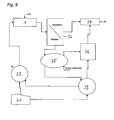
- FIG. 9 shows schematically how a jet pump 1 according to the invention can be used in a Löscheinsatz for compressed air generation.
- a high-pressure pump 32 From at least one water tapping point 31, water is sucked in by a high-pressure pump 32.
- the Water supply point 31 may be an open water point, a hydrant, a tanker or any other source of water.
- the high pressure pump 32 may be powered by a normal pressure pump 33 which is supplied from the same or another source of water.
- the normal pressure pump 33 supplies extinguishing water at a pressure of up to 10 bar.
- the jet pump 1 according to the invention is coupled to the high pressure pump 32, which has a capacity of up to 400 l / min and 40 bar to 60 bar output pressure.
- This admixed air is again separated from the water in the separator 34 connected to the outlet of the jet pump 1, the separated air still having a high pressure.
- the separated water is returned to the inlet of the normal pressure pump 33 or used via a turbo pump 35 for the preparation of a foam extract.
- the turbo-pump 35 has, for example, a delivery rate of 200 l / min to 400 l / min of water and up to 20 l / min of foam extract, although no large pressure is achieved here.
- the foam extract is generated via an admixer 36 with pressure regulator and fed to the normal pressure water of the normal pressure pump 33.
- the water-foam extract mixture is fed to a foam tube 37, which is additionally connected to the compressed-air outlet of the separator 34.
- the foam extract is foamed by the compressed air and thus processed the compressed air-extinguishing foam.
Description
Die Erfindung bezieht sich auf eine Strahlpumpe, insbesondere zum Beimischen von Luft zu einem Wasser-, Wasser/Schaummittel-, Netzmittelgemischstrahl oder dergleichen, mit einem Wassereinlass, einem Auslass für das Wasser-Luft-Gemisch und einem zwischen Einlass und Auslass angeordneten Saugraum mit einer Treibdüse, einer Fangdüse und einem Lufteinlass.The invention relates to a jet pump, in particular for admixing air to a water, water / foaming agent, wetting agent mixture jet or the like, having a water inlet, an outlet for the water-air mixture and a suction space arranged between inlet and outlet with a Heated nozzle, a catching nozzle and an air inlet.
Solche Strahlpumpen sind bekannt und können als einfache Pumpen zum Ansaugen, Absaugen oder Beimischen von Gasen oder Flüssigkeiten zu einer strömenden Flüssigkeit verwendet werden.Such jet pumps are known and can be used as simple pumps for sucking, aspirating or admixing gases or liquids to a flowing liquid.
Eine Strahlpumpe kann beispielsweise mit Wasser betrieben werden. Das Wasser gelangt durch eine Treibdüse in den Saugraum. Durch die Fliessgeschwindigkeit des Wassers innerhalb der Treibdüse entsteht an der Mündung der Treibdüse ein freier Wasserstrahl innerhalb des Saugraums.
Durch die Strahlgeschwindigkeit wird die in dem Saugraum vorhandene Luft mitgerissen und dem Strahl beigemischt, so dass in dem Saugraum ein Unterdruck entsteht, der eine erneute Luftansaugung durch eine Lufteinlassöffnung bewirkt. Der Wasserstrahl gelangt am anderen Ende der Mischkammer in eine Fangdüse und von dort zum Auslass der Strahlpumpe. Solche Strahlpumpen können jedoch nur wenig Luft aufnehmen, weshalb sie nicht geeignet sind, wenn möglichst viel Luft beigemischt werden soll und insbesondere auch nicht, wenn Gegendruck am Ausgang besteht.A jet pump can be operated, for example, with water. The water passes through a motive nozzle into the suction chamber. Due to the flow velocity of the water within the motive nozzle, a free water jet is created within the suction space at the mouth of the motive nozzle.
Due to the jet velocity, the air present in the suction space is entrained and admixed with the jet, so that a vacuum is created in the suction space arises, which causes a renewed air intake through an air inlet opening. The water jet arrives at the other end of the mixing chamber in a catching nozzle and from there to the outlet of the jet pump. However, such jet pumps can only absorb a small amount of air, which is why they are not suitable if as much air as possible is to be admixed and, in particular, not if back pressure exists at the outlet.
Ein entsprechender Apparat zur Erzeugung eines Luftschaums ist in der
Aufgabe der Erfindung ist es daher eine Strahlpumpe zum Beimischen von Gas in einen Wasser-, Wasser/Schaummittel- oder Netzmittelgemischstrahl zu schaffen, die eine größere Gasmenge beimischen, in der Fangdüse Schaum bilden, diese im Kompressionsraum verdichten und universell verwendet werden kann.The object of the invention is therefore to provide a jet pump for admixing gas in a water, water / Schaummittel- or wetting agent mixture beam that mix a larger amount of gas in the trap nozzle foam, compress them in the compression space and can be used universally.
Diese Aufgabe wird erfindungsgemäß insbesondere dadurch gelöst, dass die Leitkegel Schlitze aufweisen, die gegenüber einer Längsachse geneigt sind.This object is achieved in particular by the fact that the traffic cones have slots which are inclined relative to a longitudinal axis.
Die erfindungsgemäße Strahlpumpe weist mindestens zwei parallele Treibdüsen auf, die vom Wasser durchströmt werden. Bei insgesamt gleicher Größe der Strahlpumpe sind die einzelnen Treibdüsen entsprechend kleiner ausgeführt, als eine einzelne Treibdüse. Durch den geringeren Durchmesser der Treibdüsen entsteht eine größere Fließgeschwindigkeit des Wassers innerhalb der Treibdüsen. Beim Austritt des Wassers aus den Treibdüsen in die gemeinsame Mischkammer hat dadurch der entstehende Wasserstrahl eine größere Geschwindigkeit, wodurch unmittelbar mehr Luft angesaugt wird. Durch die Leitkegel vor den Einlass-Öffnungen der Treibdüsen erfolgt eine Verwirbelung der Wasserströmung, die dadurch von einer eingangs laminaren in eine turbulente Strömung überführt wird. Dabei erzeugen die geneigten Schlitze der Leitkegel einen Drall und dadurch eine noch grössere Verwirbelung. Beim Austritt aus den Treibdüsen entsteht dadurch ein Strahl bestehend aus einer großen Menge kleiner Tropfen, die eine große Oberfläche aufweisen und dadurch mehr Luft mitreißen. Die in der Mischkammer angesaugte Luft wird dadurch besser dem Wasser-, Wasser/Schaummittel- oder Netzmittelgemischstrahl beigemischt. Durch diese beiden Maßnahmen kann dem Wasser insgesamt mehr Luft beigemischt werden.The jet pump according to the invention has at least two parallel drive nozzles, which are traversed by the water. With a total of the same size of the jet pump, the individual motive nozzles are designed correspondingly smaller than a single motive nozzle. Due to the smaller diameter of the motive nozzles creates a greater flow velocity of the water within the motive nozzles. As the water emerges from the motive nozzles into the common mixing chamber, the resulting jet of water has a greater velocity immediately more air is sucked in. By the traffic cone in front of the inlet openings of the driving nozzles there is a turbulence of the water flow, which is thereby converted from an initial laminar into a turbulent flow. The inclined slots of the traffic cones generate a twist and thus an even greater turbulence. When leaving the motive nozzles, this creates a jet consisting of a large amount of small droplets, which have a large surface area and thus entrain more air. The sucked in the mixing chamber air is thereby better mixed with the water, water / foaming agent or wetting agent mixture jet. Through these two measures, more water can be added to the water altogether.
Der Wasserstrahl gelangt nach dem Saugraum in die Fangdüsen, die ebenfalls für jeden Wasserstrahl separat ausgeführt sind. Die Eintrittsöffnungen der Fangdüsen an der Mischkammer sind typischerweise größer als die Mündungsöffnungen der Treibdüsen. Dadurch wird sichergestellt, dass der mit Luft angereicherte Wasser-, Wasser/Schaummittel- oder Netzmittelgemischstrahl vollständig in die jeweilige Fangdüse gelangt. Durch die große Verwirbelung entsteht in der Fangdüse ein homogener, feinblasiger Löschschaum.The water jet passes to the suction chamber in the collecting nozzles, which are also designed separately for each jet of water. The inlet openings of the collecting nozzles on the mixing chamber are typically larger than the mouth openings of the driving nozzles. This ensures that the air-enriched water, water / foaming agent or wetting agent mixture jet passes completely into the respective catching nozzle. The large turbulence creates a homogeneous, fine-bubble extinguishing foam in the catching nozzle.
Die Fangdüsen münden am Ende der Strahlpumpe in einen gemeinsamen Kompressionsraum. Der Übergang zwischen Fangdüsenmündung und Kompressionsraum ist bevorzugt kontinuierlich ausgeführt. Das heißt, der Innendurchmesser des Kompressionsraums entspricht genau dem Umkreis um alle Fangdüsenmündungen. Zweckmäßigerweise befindet sich im axialen Zentrum des Kompressionsraums ein Ablenkdorn, der im wesentlichen einen Inkreis innerhalb der Fangdüsenmündungen beschriebt. Das heißt auch, dass bei der Betrachtung eines durch die Mittellängsachse der Strahlpumpe führenden Längsschnitts durch eine Fangdüse und den Kompressionsraum, die Fangdüsenwand und die Kompressionsraum-Wand eine Linie ohne eine Stufe oder einen Absatz bildet.
Dadurch kann sich das Wasser beim Austritt aus den Fangdüsen und damit beim Eintritt in den Kompressionsraum lediglich etwas zur Seite ausdehnen, so dass nur eine geringe Verwirbelung stattfindet. Dadurch wird die letztendlich am Ausgang der Strahlpumpe erreichbare Strömungsgeschwindigkeit am Teller der Hohlstrahldüse gegenüber dem Stand der Technik wesentlich erhöht. Vor allem wird der im Kompressionsraum erreichbare Gegendruck erhöht. Dies führt dazu, dass eine hohe Austrittsgeschwindigkeit erreicht wird und dadurch gegenüber herkömmlichen Geräten zu einer höheren Wurfweite führt.The catch nozzles open at the end of the jet pump in a common compression space. The transition between catch mouth and compression space is preferably carried out continuously. That is, the inner diameter of the compression space corresponds exactly to the circumference around all catch mouths. Conveniently, located in the axial center of the compression space, a Ablenkdorn, the Essr inscribes an inscribed circle substantially within the Fangdüsenmündungen. This also means that when looking through the central longitudinal axis of the jet pump leading longitudinal section through a catching nozzle and the compression chamber, the catching nozzle wall and the compression space wall a line without a step or forming a paragraph.
As a result, the water when exiting the catching nozzles and thus when entering the compression space only slightly extend to the side, so that only a small turbulence takes place. As a result, the flow velocity ultimately achievable at the outlet of the jet pump on the plate of the hollow jet nozzle is substantially increased compared to the prior art. Above all, the counterpressure achievable in the compression space is increased. As a result, a high exit velocity is achieved, resulting in a higher throw distance over conventional devices.
Der Ablenkdorn erstreckt sich vorzugsweise über die gesamte Länge des Kompressionsraums und weist am Strahlpumpenausgang eine Drossel auf, beispielsweise eine im wesentlichen konische Verbreiterung, so dass zwischen der Kompressionsraum-Innenwand und dem Ablenkdorn nur ein dünner Austrittsspalt gebildet wird. Vorzugsweise kann der Austrittsspalt veränderbar sein, beispielsweise durch axiales Verschieben der Kompressionsraum-Wand, wodurch der Druck und die Austrittsgeschwindigkeit einstellbar sind. Die Drossel ist dabei vorzugsweise einstückig mit dem Ablenkdorn ausgebildet, wobei der Übergang zwischen Ablenkdorn und Drossel ebenfalls kontinuierlich verläuft, das heißt es sind keine Stufen oder Spalte im Strömungsverlauf vorhanden, die einen StrömungsWiderstand darstellen könnten.The deflection mandrel preferably extends over the entire length of the compression space and has a throttle at the jet pump outlet, for example a substantially conical widening, so that only a thin exit gap is formed between the compression space inner wall and the deflection mandrel. Preferably, the exit gap may be changeable, for example by axial displacement of the compression space wall, whereby the pressure and the exit velocity are adjustable. The throttle is preferably formed integrally with the Ablenkdorn, wherein the transition between Ablenkdorn and throttle also runs continuously, that is, there are no steps or gaps in the flow path, which could represent a flow resistance.
Eine bevorzugte Weiterbildung der Erfindung sieht vor, dass sich die Treibdüsen in Durchflussrichtung konisch verjüngen. Durch die konisch zulaufende Form der einzelnen Treibdüsen erhöht sich in jeder Düse die Fließgeschwindigkeit des Wassers zunehmend. Die Mündungsöffnung der Treibdüse zur Mischkammer weist daher einen, im Vergleich zur Anschlussöffnung der Strahlpumpe um ein Vielfaches kleineren Durchmesser auf. Die Geschwindigkeit, mit der das Wasser in die Mischkammer schießt, ist daher um ein Vielfaches größer als bei Strahlpumpen mit nur einer zylindrischen Treibdüse.A preferred development of the invention provides that the motive nozzles taper conically in the direction of flow. Due to the tapered shape of the individual motive nozzles, the flow rate of the water increases in each nozzle increasingly. The mouth of the motive nozzle to the mixing chamber therefore has a, compared to the connection opening the jet pump to a multiple smaller diameter. The speed at which the water shoots into the mixing chamber is therefore many times greater than with jet pumps with only one cylindrical nozzle.
Eine weitere Ausführung der Erfindung sieht vor, dass die Fangdüsen einen Bereich aufweisen, in dem sich der Durchmesser in Durchflussrichtung konisch vergrößert. Die Fangdüsen sind üblicherweise über die gesamte Länge im wesentlichen zylinderförmig ausgebildet. Damit jedoch der Übergang zur Kompressionskammer übergangslos gestaltet werden kann, ist es vorteilhaft, wenn die Fangdüsen im Bereich der Mündung in die Kompressionskammer eine konische Vergrößerung aufweisen. Dadurch kann die Kompressionskammer, trotz kontinuierlichem Übergang, ein größeres Volumen aufweisen.
Die Verjüngung der Treibdüsen und/oder die Erweiterung der Fangdüsen kann auch in einer anderen Form, beispielsweise exponentiell oder parabolisch, erfolgen, jedoch ist die Herstellung konischer Öffnungen einfacher.A further embodiment of the invention provides that the catching nozzles have a region in which the diameter increases conically in the direction of flow. The collecting nozzles are usually formed substantially cylindrical over the entire length. However, so that the transition to the compression chamber can be made seamless, it is advantageous if the catching nozzles in the region of the mouth in the compression chamber have a conical enlargement. This allows the compression chamber, despite continuous transition, have a larger volume.
The tapering of the driving nozzles and / or the extension of the catching nozzles can also take place in another form, for example exponential or parabolic, but the production of conical openings is simpler.
Die erfindungsgemäße Strahlpumpe ist für die Beimischung von Gasen oder Flüssigkeiten zu einem Wasserstrahl optimiert. Sie kann in dieser Form jedoch auch zum An- oder Absaugen von Flüssigkeiten oder Gasen benutzt werden.The jet pump according to the invention is optimized for the admixture of gases or liquids to a water jet. However, it can also be used in this form to aspirate or aspirate liquids or gases.
Eine vorteilhafte Anwendung der erfindungsgemäßen Strahlpumpe ist die Erzeugung von Druckluft. Diese Anwendung eignet sich insbesondere für Feuerwehren bei Löscheinsätzen, da mit dem Löschwasser die Möglichkeit besteht, ohne zusätzlichen Aufwand auch Druckluft zu erzeugen. Die Druckluft kann dann zur Löschschaumbereitung und/oder auch für den Betrieb von hydraulischen Werkzeugen, wie beispielsweise Spreizern oder Scheren, verwendet werden. Das Mitführen eines zusätzlichen Kompressors kann somit entfallen.An advantageous application of the jet pump according to the invention is the generation of compressed air. This application is particularly suitable for fire departments in extinguishing missions, since with the extinguishing water it is possible to generate compressed air without additional effort. The compressed air can then be used for Löschschaumbereitung and / or for the operation of hydraulic tools, such as spreaders or shears. The entrainment of an additional compressor can thus be omitted.
Dazu wird die erfindungsgemäße Strahlpumpe mit dem Ausgang einer Wasserpumpe, vorzugsweise einer Hochdruckpumpe, verbunden, wie sie bei Löscheinsätzen häufig im Einsatz ist. Der Ausgang der Strahlpumpe wird mit einem Separator verbunden, in dem die in der Strahlpumpe dem Wasser beigemengte Luft wieder vom Wasser getrennt wird. Die so gewonnene Druckluft kann über ein Leitungs- und/oder Verteilersystem einem oder mehreren Verbrauchern zugeführt werden. Das abgetrennte Wasser kann danach zu Löschzwecken weiterverwendet werden oder es wird wieder dem Pumpenkreislauf zugeführt, so dass eine erneute Anreicherung mit Druckluft stattfinden kann. Auf diesem Wege ist es möglich, mit relativ wenig Brauchwasser eine kontinuierliche Druckluftversorgung zu gewährleisten. Für die Gewinnung von Druckluft ist die erfindungsgemäße Strahlpumpe insbesondere durch die erhöhte Luftbeimengung und den größeren Ausgangsdruck besonders gut geeignet.For this purpose, the jet pump according to the invention with the output of a water pump, preferably a high-pressure pump, connected, as it is often in use in extinguishing operations. The outlet of the jet pump is connected to a separator in which the air added to the water in the jet pump is again separated from the water. The compressed air thus obtained can be fed via a line and / or distribution system one or more consumers. The separated water can then be used for extinguishing purposes or it is fed back to the pump circuit, so that a re-enrichment can take place with compressed air. In this way, it is possible to ensure a continuous compressed air supply with relatively little hot water. For the production of compressed air, the jet pump according to the invention is particularly well suited, in particular by the increased air admixture and the larger outlet pressure.
Eine weitere Ausführung der Erfindung sieht vor, die Strahlpumpe direkt als Löschpistole zur Brandbekämpfung zu verwenden. Dazu kann am Ausgang der Strahlpumpe eine Strahlführung angeordnet werden, um den Löschwasserstrahl steuern zu können. Beispielsweise kann eine axial verschiebbare Hülse auf die Kompressionsraum-Wand geschoben werden, wobei durch Verschieben der Hülse zwischen Voll- und Sprühstrahl stufenlos gewählt werden kann.
Die so gebildete Löschpistole weist aufgrund der vorgenannten Vorteile eine erhöhte Auswurfweite auf, wodurch ein gezielter Löschwassereinsatz auch aus größeren und daher sichereren Entfernungen erfolgen kann.
Bevorzugt können an dem Sauggehäuse die Mengen an Luft und Schaumextrakt geregelt werden, wodurch die Schaumleistung stufenlos einstellbar ist.A further embodiment of the invention provides to use the jet pump directly as a fire extinguisher for fire fighting. For this purpose, a beam guide can be arranged at the output of the jet pump in order to control the extinguishing water jet. For example, an axially displaceable sleeve can be pushed onto the compression chamber wall, wherein it is possible to select continuously by displacing the sleeve between full jet and spray jet.
Due to the aforementioned advantages, the extinguishing pistol thus formed has an increased throw-out distance, as a result of which targeted extinguishing water use can also take place from larger and therefore safer distances.
Preferably, the amounts of air and foam extract can be controlled on the suction housing, whereby the foam performance is infinitely adjustable.
Nachfolgend ist die Erfindung anhand von bevorzugten Ausführungsbeispielen näher erläutert.The invention is explained in more detail below with reference to preferred exemplary embodiments.
Es zeigt:
- Fig. 1
- einen Längsschnitt durch eine erfindungsgemäße Strahlpumpe,
- Fig. 2
- eine Detailansicht der Strahlpumpe im Bereich des Einlasses,
- Fig. 3
- eine Vorderansicht der Strahlpumpe,
- Fig. 4
- eine Detailansicht der Strahlpumpe im Bereich der Kompressionskammer,
- Fig. 5
- einen Querschnitt durch die Kompressionskammer,
- Fig. 6
- eine Detailansicht eines Leitkegels,
- Fig. 7
- einen Längsschnitt durch eine erfindungsgemäße Löschpistole,
- Fig. 8
- einen Längsschnitt durch eine weitere Ausführung einer erfindungsgemäßen Löschpistole und
- Fig. 9
- ein Schema einer Druckluft-Schaum-Anlage mit einer erfindungsgemäßen Strahlpumpe.
- Fig. 1
- a longitudinal section through a jet pump according to the invention,
- Fig. 2
- a detailed view of the jet pump in the region of the inlet,
- Fig. 3
- a front view of the jet pump,
- Fig. 4
- a detailed view of the jet pump in the region of the compression chamber,
- Fig. 5
- a cross section through the compression chamber,
- Fig. 6
- a detailed view of a traffic cone,
- Fig. 7
- a longitudinal section through an extinguishing gun according to the invention,
- Fig. 8
- a longitudinal section through a further embodiment of an extinguishing gun according to the invention and
- Fig. 9
- a diagram of a compressed air foam system with a jet pump according to the invention.
In den
In dem Treibdüsen-Körper 3 sind kreisförmig um die Mittellängsachse neun Treibdüsen 5 angeordnet. Vor jeder Treibdüsen-Öffnung ist ein Leitkegel 6 angeordnet, der bis etwa zur Hälfte in die Treibdüse hineinragt. Die einzelnen Leitkegel 6 sind geschlitzt (
Der Leitdorn 7 sitzt auf oder vor dem Treibdüsen-Körper 3 und leitet das einströmende Wasser in die Treibdüsen 5. Dazu weist der Leitdorn 7 eine in Strömungsrichtung konisch verbreiterte Form auf, wobei der größte Durchmesser dem Inkreis 9 der kreisförmig angeordneten Treibdüsen 5 entspricht (
Die Leitkegel 6 bewirken eine Verwirbelung des einströmenden Wassers beim Eintritt in die Treibdüsen 5. Die Treibdüsen 5 sind jeweils identisch ausgebildet, wobei der Durchmesser der einzelnen Treibdüsen im Vergleich zum Durchmesser des Einlass-Stutzens 4 wesentlich geringer ist. Dadurch wird die Strömungsgeschwindigkeit des Wassers innerhalb der Treibdüsen 5 stark erhöht. Eine konische Verjüngung der Treibdüse 5 über nahezu die gesamte Länge des Treibdüsen-Körpers 3 verstärkt diesen Effekt zusätzlich. Am Ende der Treibdüse 5 ist ein kurzes zylindrisches Teilstück 8 angeordnet, das die Mündungsöffnung bildet, aus der das Wasser als Strahl aus der Treibdüse 5 austritt.The
An dem Treibdüsen-Körper 3 ist ein, im Vergleich zum Einlassstutzen 4 langer Fangdüsen-Körper 14 befestigt, der neun Fangdüsen 15 aufweist, die genau koaxial gegenüber den Treibdüsen 5 ausgerichtet sind.On the
Zwischen den Treibdüsen-Mündungen 8 und den Fangdüsen-Öffnungen 17 ist eine Lücke 18, die einen zur Umgebung offenen Saugraum bildet. Das stark beschleunigte Wasser schießt aus den engen Mündungsöffnungen 8 der Treibdüsen 5 in den Saugraum 18 und bildet dort einen freien Strahl. Der Wasserstrahl saugt Luft aus der Umgebung an und reißt diese mit sich. Durch die turbulente Strömung des Wassers, die durch die Leitkegel 6 erzeugt wird, entsteht eine Verwirbelung, durch die die Luft auch in das Innere des Wasserstrahls gelangt. Dadurch kann der Wasserstrahl mehr Luft aufnehmen. Am Ende des Saugraumes 18 gelangt der Wasser-Luft-Strahl in die Öffnung 17 der entsprechenden Fangdüse 15. Die Öffnung der Fangdüse 15 ist etwas größer als die Mündungsöffnung 8 der Treibdüse 5, damit der auf der Strecke durch den Saugraum 18 leicht aufgefächerte Strahl komplett aufgenommen werden kann. Im Weiteren folgt ein zylindrisches Teil, wo das homogene feinblasige Schaummittel gebildet wird (Schaumveredelungsstrecke).Between the blowing
An die Fangdüsen 15 schließt sich ein Kompressionsraum 20 an, der durch einen Verstellzylinder 21 umschlossen wird und in dem ein zentraler Leitdorn 22 angeordnet ist. Sowohl der Verstellzylinder 21 als auch der Leitdorn 22 sind mit dem Fangdüsen-Körper 14 verbunden, wobei der Verstellzylinder 21 in axialer Richtung verschiebbar ist. In
Ebenso ist der Innendurchmesser des Verstellzylinders 21 an den Umkreis um die Fangdüsen 15 angepasst, so dass die aus den Fangdüsen 15 austretenden Wasserstrahlen nur wenig Raum haben, sich außerhalb der Hauptstrahlrichtung zu verbreitern.
Der Leitdorn 22 verjüngt sich in Strömungsrichtung etwa konisch, wodurch das Volumen des Kompressionsraumes 20 vergrößert wird. Dadurch verliert der Wasserstrahl an Geschwindigkeit, gewinnt aber in gleichem Maß an Druck hinzu. Der Leitdorn 22 ist übergangslos mit einem Ablenkdorn 25 verbunden, der als eine im wesentlichen konische Verbreiterung des Leitdorns 22 ausgeführt ist. Ein Spalt 26 zwischen dem Ablenkdorn 25 und dem Verstellzylinder 21 bildet eine Austrittsdüse für den Wasser-Luft-Strahl. Durch axiales Verschieben des Verstellzylinders ist der Austritts-Spalt 26 und damit auch der Strahl veränderbar.Adjoining the catching
Likewise, the inner diameter of the adjusting
The
Der Treibdüsen-Körper 3 und der Fangdüsen-Körper 14 weisen jeweils eine zentrale Durchgangsbohrung auf, durch die eine zentrale Befestigungsschraube in das Gewinde 13 in dem Leitdorn 22 einschraubbar ist. Durch wenigstens einen Lagestift 16 ist sichergestellt, dass die Fangdüsen 15 exakt gegenüber den Treibdüsen 5 ausgerichtet sind.The driving
Die
In
Claims (11)
- Jet pump, in particular for admixing air to a water, water/foaming agent or water/wetting agent mixture jet, having a water inlet (2), having an outlet (26) for the water/compressed-air/foam mixture and having a suction chamber (18) which is arranged between the inlet (2) and outlet (26) and which has a propellant nozzle (5), a mixing nozzle (15) and an air inlet, with the jet pump (1) having at least two parallel propellant nozzles (5), and with in each case one guide cone (6) being arranged upstream of the inlet openings of the propellant nozzles (5), and with a separate mixing nozzle (15) being positioned downstream of each propellant nozzle (5), and with a common compression chamber (20) being positioned downstream of the mixing nozzles (15) in which the foam formation takes place, with a continuous transition being formed between the mixing nozzles (15) and the compression chamber (20), characterized in that the guide cones (6) have slots (12) which are inclined relative to a longitudinal axis.
- Jet pump according to Claim 1, characterized in that the air supply to the suction chamber can be regulated by varying the spacing between the propellant nozzles (5) and the mixing nozzles (15) .
- Jet pump according to either of Claims 1 or 2, characterized in that the propellant nozzles (5) taper conically in the throughflow direction.
- Jet pump according to one of Claims 1 to 3, characterized in that the mixing nozzles (15) have a region in which the diameter increases conically in the throughflow direction.
- Jet pump according to one of Claims 1 to 4, characterized in that a central guide peg (22) is arranged in the compression chamber (20), with the transition between the mixing nozzles (15) and the deflecting peg (22) being continuous.
- Jet pump according to one of Claims 1 to 5, characterized in that a jet regulating means (21) is arranged on the outlet.
- Jet pump according to one of Claims 1 to 6, characterized in that, for jet regulation, the housing (21) of the compression chamber (20) is movable in the longitudinal direction.
- Jet pump according to one of Claims 1 to 7, characterized in that the jet pump (1) has nine parallel propellant nozzles (5).
- Jet pump according to one of Claims 1 to 8, characterized in that the slots (12) of the guide cone (6) are of concave design.
- Extinguishing pistol having a jet pump according to one of Claims 1 to 9, characterized in that an extinguishing jet regulator (27), which is movable in the longitudinal direction, is arranged on the outlet.
- Compressed air generator having a jet pump according to one of Claims 1 to 9, having a separator (34), which is positioned downstream of the jet pump (1), for separating the compressed air from the water jet.
Applications Claiming Priority (1)
| Application Number | Priority Date | Filing Date | Title |
|---|---|---|---|
| DE200810025325 DE102008025325A1 (en) | 2008-05-27 | 2008-05-27 | Jet pump for use in e.g. compressed air generator, has suction chamber with drive nozzle arranged downstream of diffuser that is arranged downstream of compression chamber, where transition is formed between diffuser and compression chamber |
Publications (2)
| Publication Number | Publication Date |
|---|---|
| EP2128452A1 EP2128452A1 (en) | 2009-12-02 |
| EP2128452B1 true EP2128452B1 (en) | 2011-01-19 |
Family
ID=40435598
Family Applications (1)
| Application Number | Title | Priority Date | Filing Date |
|---|---|---|---|
| EP20090006154 Not-in-force EP2128452B1 (en) | 2008-05-27 | 2009-05-06 | Jet pump for production of compressed air foam |
Country Status (2)
| Country | Link |
|---|---|
| EP (1) | EP2128452B1 (en) |
| DE (2) | DE102008025325A1 (en) |
Families Citing this family (5)
| Publication number | Priority date | Publication date | Assignee | Title |
|---|---|---|---|---|
| GB2471280B (en) * | 2009-06-22 | 2011-08-31 | Hydroventuri Ltd | Apparatus and method for introducing a gas into a liquid |
| FR2975917B1 (en) * | 2011-06-06 | 2014-02-14 | Pok | DEVICE FOR GENERATING FOAM OF A FIRE LANCE |
| US10058882B1 (en) | 2017-10-20 | 2018-08-28 | Kevin J. Quinn | High pressure water/foam nozzle assembly |
| CN109806532A (en) * | 2019-03-13 | 2019-05-28 | 吕鹏 | A kind of compound jet fire extinguishing jet device |
| DE102021122710A1 (en) | 2021-09-02 | 2023-03-02 | Alfred Kärcher SE & Co. KG | POWER NOZZLE AND SURFACE CLEANING HEAD WITH ONE POWER NOZZLE |
Family Cites Families (7)
| Publication number | Priority date | Publication date | Assignee | Title |
|---|---|---|---|---|
| FR736138A (en) * | 1932-04-29 | 1932-11-19 | Vacuum pump | |
| US2373009A (en) * | 1941-06-07 | 1945-04-03 | Pyrenc Dev Corp | Fire-foam producing apparatus |
| US2577451A (en) | 1949-02-24 | 1951-12-04 | Standard Oil Dev Co | Apparatus for the production of air foam and air foam fire-extinguishing installations |
| US2946293A (en) * | 1955-04-18 | 1960-07-26 | Pyrene Co Ltd | Inductors |
| FR2619023B1 (en) * | 1987-08-07 | 1991-04-12 | Lamort E & M | PRESSURE MIXER INJECTOR |
| DE10231218A1 (en) * | 2002-07-11 | 2004-01-29 | Alstom (Switzerland) Ltd. | Atomizing device and method for producing a liquid-gas mixture |
| FR2856603B1 (en) * | 2003-06-26 | 2005-11-04 | Sides | MODULAR JET TYPE FIRE LAUNCHER |
-
2008
- 2008-05-27 DE DE200810025325 patent/DE102008025325A1/en not_active Withdrawn
-
2009
- 2009-05-06 DE DE200950000302 patent/DE502009000302D1/en active Active
- 2009-05-06 EP EP20090006154 patent/EP2128452B1/en not_active Not-in-force
Also Published As
| Publication number | Publication date |
|---|---|
| DE102008025325A1 (en) | 2009-04-16 |
| EP2128452A1 (en) | 2009-12-02 |
| DE502009000302D1 (en) | 2011-03-03 |
Similar Documents
| Publication | Publication Date | Title |
|---|---|---|
| DE60113770T2 (en) | Cleaning nozzle and cleaning device | |
| EP1115317A1 (en) | Device for producing milk froth for cappuccino | |
| EP2128452B1 (en) | Jet pump for production of compressed air foam | |
| EP2181773A1 (en) | Injection device | |
| EP3337576B1 (en) | Fire extinguisher | |
| EP3113887B1 (en) | Extension device for spraying devices and spraying device | |
| EP1852190B1 (en) | Foam device | |
| EP1470864B1 (en) | Two-fluid spray nozzle | |
| EP2578319B1 (en) | Sprinkler head | |
| DE102013002235B4 (en) | Air suction device for a sanitary shower | |
| CH702598A1 (en) | Injection nozzle and method for operating such an injection nozzle. | |
| EP0318646A2 (en) | Method and apparatus for mixing extinguishing water with a foaming or wetting agent | |
| EP1842598A1 (en) | Blasting discharge jet | |
| WO2003022525A2 (en) | Blasting method and device | |
| AT144922B (en) | Air foam generator. | |
| DE1551648A1 (en) | Atomizing burner | |
| DE654981C (en) | Air foam generator | |
| EP0880997A2 (en) | Liquid nozzle and jetting head | |
| CH201450A (en) | Air foam generator. | |
| DE1759742A1 (en) | Foam spray pipe for fire extinguishing devices or the like. | |
| CH684055A5 (en) | Launcher tube with a mixing device for producing a liquid mixture jet. | |
| DE20310119U1 (en) | Jet unit, for blasting surfaces for cleaning, has a relief jet in the connection to a liquid carbon dioxide supply, to form dry ice/snow particles to pass through a narrow pressure path into an expanding zone for acceleration | |
| DE2641195A1 (en) | Multi-component discharge and mixing nozzle - has ring of air jets discharging onto flexible ring at end of mixer chamber | |
| DE644485C (en) | Bunsen burner | |
| AT287379B (en) | Attachment for a liquid atomizer |
Legal Events
| Date | Code | Title | Description |
|---|---|---|---|
| PUAI | Public reference made under article 153(3) epc to a published international application that has entered the european phase |
Free format text: ORIGINAL CODE: 0009012 |
|
| AK | Designated contracting states |
Kind code of ref document: A1 Designated state(s): AT BE BG CH CY CZ DE DK EE ES FI FR GB GR HR HU IE IS IT LI LT LU LV MC MK MT NL NO PL PT RO SE SI SK TR |
|
| 17P | Request for examination filed |
Effective date: 20100305 |
|
| RBV | Designated contracting states (corrected) |
Designated state(s): CH DE LI |
|
| GRAP | Despatch of communication of intention to grant a patent |
Free format text: ORIGINAL CODE: EPIDOSNIGR1 |
|
| GRAS | Grant fee paid |
Free format text: ORIGINAL CODE: EPIDOSNIGR3 |
|
| GRAA | (expected) grant |
Free format text: ORIGINAL CODE: 0009210 |
|
| AK | Designated contracting states |
Kind code of ref document: B1 Designated state(s): CH DE LI |
|
| REG | Reference to a national code |
Ref country code: CH Ref legal event code: EP Ref country code: CH Ref legal event code: NV Representative=s name: KELLER & PARTNER PATENTANWAELTE AG |
|
| REF | Corresponds to: |
Ref document number: 502009000302 Country of ref document: DE Date of ref document: 20110303 Kind code of ref document: P |
|
| REG | Reference to a national code |
Ref country code: DE Ref legal event code: R096 Ref document number: 502009000302 Country of ref document: DE Effective date: 20110303 |
|
| PLBE | No opposition filed within time limit |
Free format text: ORIGINAL CODE: 0009261 |
|
| STAA | Information on the status of an ep patent application or granted ep patent |
Free format text: STATUS: NO OPPOSITION FILED WITHIN TIME LIMIT |
|
| 26N | No opposition filed |
Effective date: 20111020 |
|
| REG | Reference to a national code |
Ref country code: DE Ref legal event code: R097 Ref document number: 502009000302 Country of ref document: DE Effective date: 20111020 |
|
| REG | Reference to a national code |
Ref country code: CH Ref legal event code: PCAR Free format text: NEW ADDRESS: EIGERSTRASSE 2 POSTFACH, 3000 BERN 14 (CH) |
|
| PGFP | Annual fee paid to national office [announced via postgrant information from national office to epo] |
Ref country code: CH Payment date: 20180419 Year of fee payment: 10 Ref country code: DE Payment date: 20180517 Year of fee payment: 10 |
|
| REG | Reference to a national code |
Ref country code: DE Ref legal event code: R119 Ref document number: 502009000302 Country of ref document: DE |
|
| REG | Reference to a national code |
Ref country code: CH Ref legal event code: PL |
|
| PG25 | Lapsed in a contracting state [announced via postgrant information from national office to epo] |
Ref country code: LI Free format text: LAPSE BECAUSE OF NON-PAYMENT OF DUE FEES Effective date: 20190531 Ref country code: CH Free format text: LAPSE BECAUSE OF NON-PAYMENT OF DUE FEES Effective date: 20190531 |
|
| PG25 | Lapsed in a contracting state [announced via postgrant information from national office to epo] |
Ref country code: DE Free format text: LAPSE BECAUSE OF NON-PAYMENT OF DUE FEES Effective date: 20191203 |