EP2128418A1 - Head cover for internal combustion engine - Google Patents
Head cover for internal combustion engine Download PDFInfo
- Publication number
- EP2128418A1 EP2128418A1 EP08751646A EP08751646A EP2128418A1 EP 2128418 A1 EP2128418 A1 EP 2128418A1 EP 08751646 A EP08751646 A EP 08751646A EP 08751646 A EP08751646 A EP 08751646A EP 2128418 A1 EP2128418 A1 EP 2128418A1
- Authority
- EP
- European Patent Office
- Prior art keywords
- oil
- head cover
- prevention wall
- outflow prevention
- attachment boss
- Prior art date
- Legal status (The legal status is an assumption and is not a legal conclusion. Google has not performed a legal analysis and makes no representation as to the accuracy of the status listed.)
- Granted
Links
Images




Classifications
-
- F—MECHANICAL ENGINEERING; LIGHTING; HEATING; WEAPONS; BLASTING
- F01—MACHINES OR ENGINES IN GENERAL; ENGINE PLANTS IN GENERAL; STEAM ENGINES
- F01M—LUBRICATING OF MACHINES OR ENGINES IN GENERAL; LUBRICATING INTERNAL COMBUSTION ENGINES; CRANKCASE VENTILATING
- F01M11/00—Component parts, details or accessories, not provided for in, or of interest apart from, groups F01M1/00 - F01M9/00
- F01M11/04—Filling or draining lubricant of or from machines or engines
- F01M11/0408—Sump drainage devices, e.g. valves, plugs
-
- F—MECHANICAL ENGINEERING; LIGHTING; HEATING; WEAPONS; BLASTING
- F02—COMBUSTION ENGINES; HOT-GAS OR COMBUSTION-PRODUCT ENGINE PLANTS
- F02F—CYLINDERS, PISTONS OR CASINGS, FOR COMBUSTION ENGINES; ARRANGEMENTS OF SEALINGS IN COMBUSTION ENGINES
- F02F7/00—Casings, e.g. crankcases
- F02F7/006—Camshaft or pushrod housings
-
- F—MECHANICAL ENGINEERING; LIGHTING; HEATING; WEAPONS; BLASTING
- F01—MACHINES OR ENGINES IN GENERAL; ENGINE PLANTS IN GENERAL; STEAM ENGINES
- F01M—LUBRICATING OF MACHINES OR ENGINES IN GENERAL; LUBRICATING INTERNAL COMBUSTION ENGINES; CRANKCASE VENTILATING
- F01M11/00—Component parts, details or accessories, not provided for in, or of interest apart from, groups F01M1/00 - F01M9/00
- F01M11/04—Filling or draining lubricant of or from machines or engines
- F01M11/0408—Sump drainage devices, e.g. valves, plugs
- F01M2011/0416—Plugs
-
- F—MECHANICAL ENGINEERING; LIGHTING; HEATING; WEAPONS; BLASTING
- F01—MACHINES OR ENGINES IN GENERAL; ENGINE PLANTS IN GENERAL; STEAM ENGINES
- F01M—LUBRICATING OF MACHINES OR ENGINES IN GENERAL; LUBRICATING INTERNAL COMBUSTION ENGINES; CRANKCASE VENTILATING
- F01M11/00—Component parts, details or accessories, not provided for in, or of interest apart from, groups F01M1/00 - F01M9/00
- F01M11/04—Filling or draining lubricant of or from machines or engines
- F01M2011/0491—Filing cap with special features
Definitions
- the present invention relates to a head cover of an internal combustion engine, and particularly relates to a structure around an oil inlet of the head cover.
- a head cover of an internal combustion engine is formed with an oil inlet through which lubricating oil is supplied to a valve mechanism, etc., and a cylindrical cap attachment boss to which an oil filler cap for closing the oil inlet can be detachably attached is formed around the oil inlet.
- the cylindrical cap attachment boss is formed on the head cover as a protrusion, and the oil inlet is formed inside of the attachment boss as an opening.
- head covers are formed with an oil outflow prevention wall (barrier) that surrounds the cap attachment boss to defme an oil trap portion around the cap attachment boss in order to prevent the oil that has been accidentally poured or spilt outside of the cap attachment boss when oil is supplied through the oil inlet from spreading over a wide area to contaminate a considerable portion of the head cover (see Japanese Utility Model Application Laid-Open Publication No. 61-175514 , for example).
- barrier oil outflow prevention wall
- an internal combustion engine (cylinder block) may be mounted transversely in such a manner that a cylinder axis is inclined with respect to a vertical line.
- Such an engine may be called an inclined engine.
- an upper surface of a cylinder head to which the head cover is fastened is inclined with respect to a horizontal plane, and hence the head cover is also inclined with respect to the horizontal plane in the installed state.
- the upper end of the oil outflow prevention wall extends horizontally when the cylinder head is positioned horizontally. This can cause a problem in the inclined engine that in a lower side of the inclination, the oil spilt from the cap attachment boss can easily get over the oil outflow prevention wall to outside.
- An object to be achieved by the present invention is to prevent the spilt oil from flowing to an undesired part in an inclined engine without compromising the easiness of oil supplying work as well as attachment and detachment of the oil filler cap.
- the present invention provides a head cover of an internal combustion engine in which a fastening plane between the head cover and an engine main body is inclined with respect to a horizontal plane when the engine is mounted in a vehicle, the head cover comprising: a cap attachment boss to which an oil filler cap can be detachably attached, the cap attachment boss having an oil inlet inside thereof; and an oil outflow prevention wall formed around the cap attachment boss, wherein an oil trap portion surrounding the cap attachment boss is defined between the cap attachment boss and the oil outflow preventing wall, and wherein a height of an upper end of the oil outflow prevention wall with respect to the fastening plane becomes greater toward a lower side of the inclination of the fastening plane.
- the present invention provides a head cover of an internal combustion engine in which a fastening plane between the head cover and an engine main body is inclined with respect to a horizontal plane when the engine is mounted in a vehicle, the head cover comprising: a cap attachment boss to which an oil filler cap can be detachably attached, the cap attachment boss having an oil inlet inside thereof; and an oil outflow prevention wall formed around the cap attachment boss, wherein an oil trap portion surrounding the cap attachment boss is defined between the cap attachment boss and the oil outflow preventing wall, and wherein a height of an upper end of the oil outflow prevention wall with respect to the fastening plane is greater in a lower side of the inclination of the fastening plane than in a higher side of the inclination of the fastening plane.
- the oil outflow prevention wall comprises a part having a greater height than a height of the cap attachment boss in a lower side of the inclination of the fastening plane, and a part having a smaller height than the height of the cap attachment boss in a higher side of the inclination of the fastening plane.
- an upper end surface of the oil outflow prevention wall extends substantially horizontally in an installed state in the vehicle.
- a part of the oil outflow prevention wall is provided with an oil discharge opening.
- a bottom of the oil trap portion is provided with a downward slope toward the oil discharge opening in an installed state in the vehicle.
- the cap attachment boss is formed in a vicinity of one end of the head cover with respect to a crankshaft direction, and the oil outflow prevention wall comprises a part that extends along an edge of the one end of the head cover.
- the oil outflow prevention wall has a greater height in the lower side of the inclination, where the oil tends to flow out, than in the higher side of the inclination in an inclined engine, it is difficult for the oil to get over the oil outflow prevention wall to outside and thus outflow of oil to an undesired part can be prevented. Further, because the part of the oil outflow prevention wall in the higher side of the inclination has a smaller height than in the lower side of the inclination, favorable workability can be ensured in supplying oil and attaching/detaching the oil filler cap.
- the oil outflow prevention wall comprises a part having a greater height than a height of the cap attachment boss in a lower side of the inclination of the fastening plane (i.e., in a region where the oil tends to flow out), and a part having a smaller height than the height of the cap attachment boss in a higher side of the inclination of the fastening plane (i.e., in a region where the oil is difficult to flow out), it is possible to favorably achieve both of prevention of oil outflow to an undesired part and easy attachment/detachment of the oil filler cap.
- an upper end surface of the oil outflow prevention wall extends substantially horizontally in an installed state in the vehicle, it is possible to eliminate a part in the oil outflow prevention wall where the oil can easily get over, and thereby prevent the oil from flowing out to an undesired part when the head cover is inclined in the installed state in the vehicle.
- the oil outflow prevention wall is provided with an oil discharge opening in a part thereof, it is possible to desirably set a position at which the oil flows out from the oil trap portion to outside by properly selecting the position of the oil discharge opening, to thereby ensure that the oil is prevented from flowing out to an undesired part, i.e., a part where the oil should be avoided or where it is difficult to wipe out the oil, such as a portion where the timing belt is disposed.
- the bottom of the oil trap portion is provided with a downward slope toward the oil discharge opening in an installed state in the vehicle, the discharge of oil from the oil discharge opening can be achieved smoothly and reliably.
- the rigidity of the end portion of the head cover can be improved and the improved rigidity can result in a better sealing surface pressure of the head cover.
- FIG 1 is a plan view showing an essential part of an internal combustion engine 100 having a head cover 10 according to this embodiment.
- the engine 100 consists of a straight four-cylinder gasoline engine, and is mounted transversely in a vehicle.
- a lower side of the sheet corresponds to a vehicle front F while an upper side of the sheet corresponds to a vehicle rear R.
- the engine 100 is a rearward inclined engine in that a part on a side of the head cover 10 (engine upper part) is inclined toward the vehicle rear R around a crankshaft axis.
- An angle ⁇ (see Figure 5 ) of the rearward inclination of the engine 100 can be about 5-10 degrees.
- a reference numeral 101 indicates an intake surge tank disposed over the head cover 10
- 102 indicates an intake manifold disposed on a side of the vehicle front F
- 103 indicates an exhaust manifold disposed on a side of the vehicle rear R
- 105 indicates a timing belt disposed at an engine end (one end of the engine in a direction of cylinder arrangement) to drive an auxiliary machinery and the like.
- the head cover 10 consists of a lid-like member longitudinal in the direction of cylinder arrangement of the engine 100, and is made by molding a resin material such as glass-fiber reinforced polyamide resin.
- the head cover 10 is securely fastened to an upper surface of a cylinder head 106 by means of fastening bolts 13 passed through corresponding through holes 12 defined in bolt boss portions 11 which are formed at a plurality of locations along an outer periphery of the head cover 10.
- a fastening plane 15 between the head cover 10 and the cylinder head 106 constituting an engine main body is inclined with respect to a horizontal plane h with the rearward inclination angle ⁇ (see Figure 5 ).
- the head cover 10 is formed with a cylindrical cap attachment boss 21 in one end portion in the direction of cylinder arrangement, and more specifically in an end portion of an upper surface 14 on the same side as the timing belt 105 and on the side of the vehicle front F.
- the cap attachment boss 21 has an oil inlet 22 inside of it.
- the oil inlet 22 consists of a round opening extending through the upper surface 14 of the head cover 10 in a vertical direction.
- the cap attachment boss 21 is adapted so as to be detachably attached with an oil filler cap 23 (see Figure 1 ) for closing the oil inlet 22.
- the cap attachment boss 21 is formed with a cap engaging threads 24 in its inner peripheral surface.
- the upper surface 14 of the head cover 10 is also formed with an oil outflow prevention wall 25 which protrudes from the upper surface 14 so as to surround the cap attachment boss 21. Between the cap attachment boss 21 and the oil outflow prevention wall 25 is defined an oil trap portion 27 that surrounds the cap attachment boss 21. It should be noted that the cap attachment boss 21 and the oil outflow prevention wall 25 are integral parts of the head cover 10.
- a height of an upper end of the oil outflow prevention wall 25 with respect to the fastening plane 15 becomes greater toward a lower side of the inclination of the fastening plane 15 (toward left side in Figure 5 or toward vehicle rear R).
- the height of the upper end of the oil outflow prevention wall 25 with respect to the fastening plane 15 is greater in a lower side of the inclination of the fastening plane 15 than in a higher side of the inclination of the fastening plane 15.
- the largest wall height in the lower side of the inclination is indicated by Ha
- the smallest wall height in the higher side of the inclination is indicated by Hb.
- an upper end surface 26 of the oil outflow prevention wall 25 extends substantially in the horizontal direction in an installed state in the vehicle.
- the oil outflow prevention wall 25 comprises a part (high wall part) 25A having a greater height than a height Hc of the cap attachment boss 21 in a lower side of the inclination of the fastening plane 15, and a part (low wall part) 25B having a smaller height than the height Hc of the cap attachment boss in a higher side of the inclination of the fastening plane 15.
- At least part of the oil outflow prevention wall 25 that is on the side of vehicle front F (on the higher side of the inclination) with respect to the center of the cap attachment boss 21 has a smaller height than the height Hc of the cap attachment boss 21, and at least part of the oil outflow prevention wall 25 that is on the side of vehicle rear R (on the lower side of the inclination) with respect to the center of the cap attachment boss 21 has a greater height than the height Hc of the cap attachment boss 21, where the heights are measured from the fastening plane 15.
- the high wall portion 25A of the oil outflow prevention wall 25 in the present embodiment extends over a greater range than an outer diameter Db of the cap attachment boss 21 on the side of the vehicle rear R (lower side of the inclination) with respect to the cap attachment boss portion 21.
- more than a half of the oil outflow prevention wall 25 surrounding the cap attachment boss 21 belongs to the low wall portion 25B.
- all of the part of oil outflow prevention wall 25 that is on the side of the vehicle front F (upper side of the inclination) with respect to the center of the cap attachment boss 21 and a part of the oil outflow prevention wall 25 that is slightly on the side of vehicle rear R (lower side of the inclination) constitute the low wall portion 25B.
- a step is formed at a connection between the high wall portion 25A and the low wall portion 25B which have different heights.
- the oil outflow prevention wall 25 is set as above, specifically, the oil outflow prevention wall 25 is given a greater height in the lower side of the inclination, where the outflow of oil is likely to take place, than in the higher side of the inclination, it is difficult for the spilt oil to get over the oil outflow prevention wall 25 to undesired parts such as those on the side of vehicle rear R. Further, because the part of the oil outflow prevention wall 25 in the higher side of the inclination has a smaller height than in the lower side of the inclination, favorable workability can be ensured in supplying oil from the side of vehicle front F and attaching/detaching the oil filler cap.
- a part of the oil outflow prevention wall 25 is formed with an oil discharge opening 28.
- the oil discharge opening 28 is provided in a part of the oil outflow prevention wall 25 on the side of vehicle front F (upper side of the inclination) so that when the spilt oil flows out, it flows to a space between the intake manifold 102 and an exhaust gas recirculation valve 104, where the space serves as a desired part.
- the work for wiping out the spilt oil can be conducted easily from the side of vehicle front F, and this contributes to improvement in maintainability.
- contamination of the timing belt 105 by the spilt oil can be avoided.
- the bottom of the oil trap portion 27 is provided with a downward slope (slant) toward the oil discharge opening 28 so that the spilt oil is caused to flow toward the desired part smoothly through the oil discharge opening 28.
- the oil outflow prevention wall 25 comprises a part 25C that extends along an edge 10C of one end of the head cover 10 with respect to the crankshaft direction.
- This part 25C also serves as a reinforcement rib for increasing the rigidity of the head cover 10.
- the part 25C is effective in improving the rigidity of the side edge of the head cover 10 and hence in increasing the sealing pressure provided by the fastening bolts 13 along a portion between widthwise-apart fastening points A and B (see Figure 1 ).
- a seal member 16 made of an elastic material is provided on the fastening plane 15 of the head cover 10 so as to extend along an outer periphery of the head cover 10.
- the above part 25C of the oil outflow prevention wall 25 is positioned substantially right above a part of the seal member 16 that extends along the crankshaft-wise end 10C of the head cover 10.
- the part 25C extends between the two fastening points A and B of the head cover 10, and is formed over a length equal to or greater than at least a half (L/2) of the length L of the side edge of the head cover 10 in the direction of connecting the two fastening points A and B so that the length is larger than an outer diameter of the filler cap attachment boss 21.
- the part 25C is provided with a larger thickness compared to other part of the oil outflow prevention wall 25.
- the illustrated layout of the head cover 10 and shape of the oil outflow prevention wall 25 are just an example, and the present invention should not be limited to the illustrated embodiment.
- a step is provided in the oil outflow prevention wall 25 to accommodate a large difference in height between the portions of the oil outflow prevention wall 25 on the front and rear sides of the oil filler cap, but as shown by phantom lines S in Figure 5 , the upper end of the oil outflow prevention wall 25 may extend substantially straight smoothly. Further, the upper end surface of the oil outflow prevention wall 25 does not have to be accurately horizontal but may be approximately horizontal.
- the cap attachment boss 21 may not be limited to the one that extends vertically with respect to the fastening plane of the head cover 10, and may be inclined forward, for example, to improve the maintainability.
- Figures 6 and 7 show another embodiment of the head cover according to the present invention.
- component parts corresponding to those in Figures 3 and 4 are denoted with the same reference numerals as in Figures 3 and 4 , and detailed explanation thereof is omitted.
- a protruding rib 29 for reinforcement is integrally formed to the head cover 10 so as to extend along the edge 10C of the head cover 10 in a portion outside of the oil outflow prevention wall 25.
- the protruding rib 29 not only contributes to the improvement of rigidity but also serves as an additional oil outflow prevention wall that defines another oil trap portion 30 in the end portion of the head cover 10. This can prevent the outflow of oil to an undesired part even more reliably.
Landscapes
- Engineering & Computer Science (AREA)
- Mechanical Engineering (AREA)
- General Engineering & Computer Science (AREA)
- Chemical & Material Sciences (AREA)
- Combustion & Propulsion (AREA)
- Lubrication Details And Ventilation Of Internal Combustion Engines (AREA)
- Cylinder Crankcases Of Internal Combustion Engines (AREA)
Abstract
Description
- The present invention relates to a head cover of an internal combustion engine, and particularly relates to a structure around an oil inlet of the head cover.
- A head cover of an internal combustion engine is formed with an oil inlet through which lubricating oil is supplied to a valve mechanism, etc., and a cylindrical cap attachment boss to which an oil filler cap for closing the oil inlet can be detachably attached is formed around the oil inlet. Thus, the cylindrical cap attachment boss is formed on the head cover as a protrusion, and the oil inlet is formed inside of the attachment boss as an opening.
- Some of such head covers are formed with an oil outflow prevention wall (barrier) that surrounds the cap attachment boss to defme an oil trap portion around the cap attachment boss in order to prevent the oil that has been accidentally poured or spilt outside of the cap attachment boss when oil is supplied through the oil inlet from spreading over a wide area to contaminate a considerable portion of the head cover (see Japanese Utility Model Application Laid-Open Publication No.
61-175514 - In some of the vehicles such as automobiles, an internal combustion engine (cylinder block) may be mounted transversely in such a manner that a cylinder axis is inclined with respect to a vertical line. Such an engine may be called an inclined engine. In the inclined engine, an upper surface of a cylinder head to which the head cover is fastened is inclined with respect to a horizontal plane, and hence the head cover is also inclined with respect to the horizontal plane in the installed state.
- In this regard, in the conventional head cover, the upper end of the oil outflow prevention wall extends horizontally when the cylinder head is positioned horizontally. This can cause a problem in the inclined engine that in a lower side of the inclination, the oil spilt from the cap attachment boss can easily get over the oil outflow prevention wall to outside.
- The higher the oil outflow prevention wall is, the harder the oil flows over the oil outflow prevention wall to outside. However, the higher the oil outflow prevention wall is, the more difficult it becomes to access the oil inlet to supply the oil and to attach or detach the oil filler cap to and from the attachment boss. Further, a higher oil outflow prevention wall can lead to a greater overall height of the engine and thus may compromise an advantage of the inclined engine that the inclined engine can assume a smaller height when installed in the vehicle.
- An object to be achieved by the present invention is to prevent the spilt oil from flowing to an undesired part in an inclined engine without compromising the easiness of oil supplying work as well as attachment and detachment of the oil filler cap.
- The present invention provides a head cover of an internal combustion engine in which a fastening plane between the head cover and an engine main body is inclined with respect to a horizontal plane when the engine is mounted in a vehicle, the head cover comprising: a cap attachment boss to which an oil filler cap can be detachably attached, the cap attachment boss having an oil inlet inside thereof; and an oil outflow prevention wall formed around the cap attachment boss, wherein an oil trap portion surrounding the cap attachment boss is defined between the cap attachment boss and the oil outflow preventing wall, and wherein a height of an upper end of the oil outflow prevention wall with respect to the fastening plane becomes greater toward a lower side of the inclination of the fastening plane.
- Also, the present invention provides a head cover of an internal combustion engine in which a fastening plane between the head cover and an engine main body is inclined with respect to a horizontal plane when the engine is mounted in a vehicle, the head cover comprising: a cap attachment boss to which an oil filler cap can be detachably attached, the cap attachment boss having an oil inlet inside thereof; and an oil outflow prevention wall formed around the cap attachment boss, wherein an oil trap portion surrounding the cap attachment boss is defined between the cap attachment boss and the oil outflow preventing wall, and wherein a height of an upper end of the oil outflow prevention wall with respect to the fastening plane is greater in a lower side of the inclination of the fastening plane than in a higher side of the inclination of the fastening plane.
- In the head cover of an internal combustion engine according to the present invention, preferably, the oil outflow prevention wall comprises a part having a greater height than a height of the cap attachment boss in a lower side of the inclination of the fastening plane, and a part having a smaller height than the height of the cap attachment boss in a higher side of the inclination of the fastening plane.
- In the head cover of an internal combustion engine according to the present invention, preferably, an upper end surface of the oil outflow prevention wall extends substantially horizontally in an installed state in the vehicle.
- In the head cover of an internal combustion engine according to the present invention, preferably, a part of the oil outflow prevention wall is provided with an oil discharge opening.
- In the head cover of an internal combustion engine according to the present invention, preferably, a bottom of the oil trap portion is provided with a downward slope toward the oil discharge opening in an installed state in the vehicle.
- In the head cover of an internal combustion engine according to the present invention, preferably, the cap attachment boss is formed in a vicinity of one end of the head cover with respect to a crankshaft direction, and the oil outflow prevention wall comprises a part that extends along an edge of the one end of the head cover.
- In the head cover of an internal combustion engine according to the present invention, because the oil outflow prevention wall has a greater height in the lower side of the inclination, where the oil tends to flow out, than in the higher side of the inclination in an inclined engine, it is difficult for the oil to get over the oil outflow prevention wall to outside and thus outflow of oil to an undesired part can be prevented. Further, because the part of the oil outflow prevention wall in the higher side of the inclination has a smaller height than in the lower side of the inclination, favorable workability can be ensured in supplying oil and attaching/detaching the oil filler cap.
- Particularly, in the structure where the oil outflow prevention wall comprises a part having a greater height than a height of the cap attachment boss in a lower side of the inclination of the fastening plane (i.e., in a region where the oil tends to flow out), and a part having a smaller height than the height of the cap attachment boss in a higher side of the inclination of the fastening plane (i.e., in a region where the oil is difficult to flow out), it is possible to favorably achieve both of prevention of oil outflow to an undesired part and easy attachment/detachment of the oil filler cap.
- In the case where an upper end surface of the oil outflow prevention wall extends substantially horizontally in an installed state in the vehicle, it is possible to eliminate a part in the oil outflow prevention wall where the oil can easily get over, and thereby prevent the oil from flowing out to an undesired part when the head cover is inclined in the installed state in the vehicle.
- Further, in the case that the oil outflow prevention wall is provided with an oil discharge opening in a part thereof, it is possible to desirably set a position at which the oil flows out from the oil trap portion to outside by properly selecting the position of the oil discharge opening, to thereby ensure that the oil is prevented from flowing out to an undesired part, i.e., a part where the oil should be avoided or where it is difficult to wipe out the oil, such as a portion where the timing belt is disposed. Further, when the bottom of the oil trap portion is provided with a downward slope toward the oil discharge opening in an installed state in the vehicle, the discharge of oil from the oil discharge opening can be achieved smoothly and reliably.
- In the structure where the cap attachment boss is formed in the vicinity of one end of the head cover with respect to the crankshaft direction and the oil outflow prevention wall comprises a part extending along an edge of the crankshaft-wise end of the head cover, the rigidity of the end portion of the head cover can be improved and the improved rigidity can result in a better sealing surface pressure of the head cover.
- Now the present invention is described in the following with reference to the appended drawings, in which:
-
Figure 1 is a plan view showing an essential part of an internal combustion engine comprising a head cover according to the present invention; -
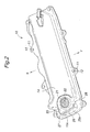
Figure 2 is a perspective view showing an embodiment of a head cover according to the present invention; -
Figure 3 is an enlarged plan view of an essential part of the head cover according to the embodiment; -
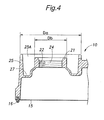
Figure 4 is a cross-sectional view taken along the line IV-IV inFigure 3 ; -
Figure 5 is an enlarged plan view of an essential part of the head cover according to the embodiment; -
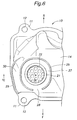
Figure 6 is an enlarged plan view of an essential part of another embodiment of a head cover according to the present invention; and -
Figure 7 is cross-sectional view taken along the line VII-VII inFigure 6 . - Now, an embodiment of a head cover of an internal combustion engine according to the present invention will be described hereinafter with reference to
Figures 1-5 . -
Figure 1 is a plan view showing an essential part of aninternal combustion engine 100 having ahead cover 10 according to this embodiment. Theengine 100 consists of a straight four-cylinder gasoline engine, and is mounted transversely in a vehicle. InFigure 1 , a lower side of the sheet corresponds to a vehicle front F while an upper side of the sheet corresponds to a vehicle rear R. Theengine 100 is a rearward inclined engine in that a part on a side of the head cover 10 (engine upper part) is inclined toward the vehicle rear R around a crankshaft axis. An angle θ (seeFigure 5 ) of the rearward inclination of theengine 100 can be about 5-10 degrees. - In
Figure 1 , areference numeral 101 indicates an intake surge tank disposed over thehead cover - The
head cover 10 consists of a lid-like member longitudinal in the direction of cylinder arrangement of theengine 100, and is made by molding a resin material such as glass-fiber reinforced polyamide resin. Thehead cover 10 is securely fastened to an upper surface of acylinder head 106 by means of fasteningbolts 13 passed through corresponding throughholes 12 defined inbolt boss portions 11 which are formed at a plurality of locations along an outer periphery of thehead cover 10. As a result, when installed in the vehicle, afastening plane 15 between thehead cover 10 and thecylinder head 106 constituting an engine main body is inclined with respect to a horizontal plane h with the rearward inclination angle θ (seeFigure 5 ). - The
head cover 10 is formed with a cylindricalcap attachment boss 21 in one end portion in the direction of cylinder arrangement, and more specifically in an end portion of anupper surface 14 on the same side as thetiming belt 105 and on the side of the vehicle front F. Thecap attachment boss 21 has anoil inlet 22 inside of it. Theoil inlet 22 consists of a round opening extending through theupper surface 14 of thehead cover 10 in a vertical direction. - The
cap attachment boss 21 is adapted so as to be detachably attached with an oil filler cap 23 (seeFigure 1 ) for closing theoil inlet 22. In the case that theoil filler cap 23 is of a screw type, thecap attachment boss 21 is formed with a capengaging threads 24 in its inner peripheral surface. - The
upper surface 14 of thehead cover 10 is also formed with an oiloutflow prevention wall 25 which protrudes from theupper surface 14 so as to surround thecap attachment boss 21. Between thecap attachment boss 21 and the oiloutflow prevention wall 25 is defined anoil trap portion 27 that surrounds thecap attachment boss 21. It should be noted that thecap attachment boss 21 and the oiloutflow prevention wall 25 are integral parts of thehead cover 10. - One thing that is important in the
head cover 10 of the illustrated embodiment is that a height of an upper end of the oiloutflow prevention wall 25 with respect to thefastening plane 15 becomes greater toward a lower side of the inclination of the fastening plane 15 (toward left side inFigure 5 or toward vehicle rear R). In other words, the height of the upper end of the oiloutflow prevention wall 25 with respect to thefastening plane 15 is greater in a lower side of the inclination of thefastening plane 15 than in a higher side of the inclination of thefastening plane 15. InFigure 5 , the largest wall height in the lower side of the inclination is indicated by Ha, while the smallest wall height in the higher side of the inclination is indicated by Hb. It should be also noted that anupper end surface 26 of the oiloutflow prevention wall 25 extends substantially in the horizontal direction in an installed state in the vehicle. - In addition to the above, the oil
outflow prevention wall 25 comprises a part (high wall part) 25A having a greater height than a height Hc of thecap attachment boss 21 in a lower side of the inclination of thefastening plane 15, and a part (low wall part) 25B having a smaller height than the height Hc of the cap attachment boss in a higher side of the inclination of thefastening plane 15. - In this embodiment, at least part of the oil
outflow prevention wall 25 that is on the side of vehicle front F (on the higher side of the inclination) with respect to the center of thecap attachment boss 21 has a smaller height than the height Hc of thecap attachment boss 21, and at least part of the oiloutflow prevention wall 25 that is on the side of vehicle rear R (on the lower side of the inclination) with respect to the center of thecap attachment boss 21 has a greater height than the height Hc of thecap attachment boss 21, where the heights are measured from thefastening plane 15. - As indicated by a reference numeral Da in
Figure 4 , thehigh wall portion 25A of the oiloutflow prevention wall 25 in the present embodiment extends over a greater range than an outer diameter Db of thecap attachment boss 21 on the side of the vehicle rear R (lower side of the inclination) with respect to the capattachment boss portion 21. - Further, in this embodiment, more than a half of the oil
outflow prevention wall 25 surrounding thecap attachment boss 21 belongs to thelow wall portion 25B. Specifically, all of the part of oiloutflow prevention wall 25 that is on the side of the vehicle front F (upper side of the inclination) with respect to the center of thecap attachment boss 21 and a part of the oiloutflow prevention wall 25 that is slightly on the side of vehicle rear R (lower side of the inclination) constitute thelow wall portion 25B. It should be noted that a step is formed at a connection between thehigh wall portion 25A and thelow wall portion 25B which have different heights. - Because the height of the oil
outflow prevention wall 25 is set as above, specifically, the oiloutflow prevention wall 25 is given a greater height in the lower side of the inclination, where the outflow of oil is likely to take place, than in the higher side of the inclination, it is difficult for the spilt oil to get over the oiloutflow prevention wall 25 to undesired parts such as those on the side of vehicle rear R. Further, because the part of the oiloutflow prevention wall 25 in the higher side of the inclination has a smaller height than in the lower side of the inclination, favorable workability can be ensured in supplying oil from the side of vehicle front F and attaching/detaching the oil filler cap. - A part of the oil
outflow prevention wall 25 is formed with anoil discharge opening 28. In this embodiment, theoil discharge opening 28 is provided in a part of the oiloutflow prevention wall 25 on the side of vehicle front F (upper side of the inclination) so that when the spilt oil flows out, it flows to a space between theintake manifold 102 and an exhaustgas recirculation valve 104, where the space serves as a desired part. In this way, the work for wiping out the spilt oil can be conducted easily from the side of vehicle front F, and this contributes to improvement in maintainability. In addition, contamination of thetiming belt 105 by the spilt oil can be avoided. - The bottom of the
oil trap portion 27 is provided with a downward slope (slant) toward the oil discharge opening 28 so that the spilt oil is caused to flow toward the desired part smoothly through theoil discharge opening 28. - The oil
outflow prevention wall 25 comprises apart 25C that extends along anedge 10C of one end of thehead cover 10 with respect to the crankshaft direction. Thispart 25C also serves as a reinforcement rib for increasing the rigidity of thehead cover 10. Thus, in addition to protect theoil filler cap 23 attached to thecap attachment boss 21, thepart 25C is effective in improving the rigidity of the side edge of thehead cover 10 and hence in increasing the sealing pressure provided by thefastening bolts 13 along a portion between widthwise-apart fastening points A and B (seeFigure 1 ). - A
seal member 16 made of an elastic material is provided on thefastening plane 15 of thehead cover 10 so as to extend along an outer periphery of thehead cover 10. Theabove part 25C of the oiloutflow prevention wall 25 is positioned substantially right above a part of theseal member 16 that extends along thecrankshaft-wise end 10C of thehead cover 10. - In this embodiment, the
part 25C extends between the two fastening points A and B of thehead cover 10, and is formed over a length equal to or greater than at least a half (L/2) of the length L of the side edge of thehead cover 10 in the direction of connecting the two fastening points A and B so that the length is larger than an outer diameter of the fillercap attachment boss 21. In order to effectively serve as a reinforcing rib for improving the rigidity, thepart 25C is provided with a larger thickness compared to other part of the oiloutflow prevention wall 25. - The beneficial effects of the
head cover 10 of the present embodiment can be summarized as follows: - (1) Because the oil
outflow prevention wall 25 has a greater height in the lower side of the inclination, where the oil spilt from thecap attachment boss 21 tends to flow out, than in the higher side of the inclination where the oil is difficult to flow out, it is possible to prevent the spilt oil from flowing to an undesired part when thehead cover 10 is inclined in the state that theengine 100 is mounted in the vehicle. - (2) In the case where the
fastening plane 15 between thehead cover 10 and the engine main body is inclined in the installed state in the vehicle, at least part of the oiloutflow prevention wall 25 that is on a front side with respect to the center of thecap attachment boss 21, to which theoil filler cap 23 is attached, is given a smaller height than thecap attachment boss 21, and at least part of the oiloutflow prevention wall 25 that is on a rear side with respect to the center of thecap attachment boss 21 is given a larger height than thecap attachment boss 21. Thus, by providing a greater height to the portion of the oiloutflow prevention wall 25 on the rear side, where the oil tends to flow out, than thecap attachment boss 21, it is possible to prevent the spilt oil from flowing out to an undesired part. Further, by providing a smaller height to the portion of the oiloutflow prevention wall 25 on the front side, where the oil is hard to flow out, than thecap attachment boss 21, it is possible to easily attach/detach the oil filler cap from the front side, to thereby improve the maintainability. - (3) The oil discharge opening 28 provided in the front part of the oil
outflow prevention wall 25 and the forwardly downward slope constituting the bottom of the oil trap space (oil trap portion 27) defined between thecap attachment boss 21 and the oiloutflow prevention wall 25 allows the spilt oil to be guided and discharged to the front side. Therefore, it can be ensured that the oil is prevented from flowing out to a part where the oil should be avoided or where it is difficult to wipe out the oil such as a part where the timing belt is disposed. - (4) By making the
upper end surface 26 of the oiloutflow prevention wall 25 extend substantially horizontally in the installed state in the vehicle, it is possible to eliminate a part in the oiloutflow prevention wall 25 where the oil can easily get over, and thereby prevent the oil from flowing out to an undesired part when thehead cover 10 is inclined in the installed state in the vehicle. - (5) In the case where the
cap attachment boss 21 is formed in a portion that is on the higher side of the inclination of thefastening plane 15 of thehead cover 10 with respect to the center of thehead cover 10 and near one end in the crankshaft direction, it is possible to constitute the oiloutflow prevention wall 25 as a protruding rib (part 25C) extending substantially along theedge 10C of the one end of thehead cover 10, to whereby improve the rigidity of the portion around theedge 10C of thehead cover 10, and the improved rigidity can result in a better sealing surface pressure of thehead cover 10. The protruding rib has a greater height around the central portion of thehead cover 10, and therefore, the protruding rib for preventing the oil outflow can also serve effectively as a rib for protecting theoil filler cap 23 as well as a rib for improving the rigidity of a portion around the oil filler cap. This can eliminate the need for providing a reinforcement rib or protection rib around the oil filler cap in addition to the oiloutflow prevention wall 25, and thus simplify the structure and reduce the cost. - It should be noted that the illustrated layout of the
head cover 10 and shape of the oiloutflow prevention wall 25 are just an example, and the present invention should not be limited to the illustrated embodiment. In the above embodiment, a step is provided in the oiloutflow prevention wall 25 to accommodate a large difference in height between the portions of the oiloutflow prevention wall 25 on the front and rear sides of the oil filler cap, but as shown by phantom lines S inFigure 5 , the upper end of the oiloutflow prevention wall 25 may extend substantially straight smoothly. Further, the upper end surface of the oiloutflow prevention wall 25 does not have to be accurately horizontal but may be approximately horizontal. Thecap attachment boss 21 may not be limited to the one that extends vertically with respect to the fastening plane of thehead cover 10, and may be inclined forward, for example, to improve the maintainability. -
Figures 6 and7 show another embodiment of the head cover according to the present invention. InFigures 6 and7 , component parts corresponding to those inFigures 3 and4 are denoted with the same reference numerals as inFigures 3 and4 , and detailed explanation thereof is omitted. - In this embodiment, in addition to the oil
outflow prevention wall 25 surrounding thecap attachment boss 21, a protrudingrib 29 for reinforcement is integrally formed to thehead cover 10 so as to extend along theedge 10C of thehead cover 10 in a portion outside of the oiloutflow prevention wall 25. - The protruding
rib 29 not only contributes to the improvement of rigidity but also serves as an additional oil outflow prevention wall that defines anotheroil trap portion 30 in the end portion of thehead cover 10. This can prevent the outflow of oil to an undesired part even more reliably. - The disclosure of the original Japanese patent application (Japanese Patent Application No.
2007-130265 filed on May 16, 2007
Claims (7)
- A head cover (10) of an internal combustion engine in which a fastening plane (15) between the head cover and an engine main body (106) is inclined with respect to a horizontal plane when the engine is mounted in a vehicle, the head cover comprising:a cap attachment boss (21) to which an oil filler cap (23) can be detachably attached, the cap attachment boss having an oil inlet inside thereof; andan oil outflow prevention wall (25) formed around the cap attachment boss,wherein an oil trap portion (27) surrounding the cap attachment boss is defined between the cap attachment boss and the oil outflow preventing wall,and wherein a height of an upper end of the oil outflow prevention wall with respect to the fastening plane is greater in a lower side of the inclination of the fastening plane than in a higher side of the inclination of the fastening plane.
- The head cover according to claim 1, wherein the height of the upper end of the oil outflow prevention wall with respect to the fastening plane becomes greater toward the lower side of the inclination of the fastening plane.
- The head cover according to claim 1, wherein the oil outflow prevention wall comprises a part having a greater height than a height of the cap attachment boss in a lower side of the inclination of the fastening plane, and a part having a smaller height than the height of the cap attachment boss in a higher side of the inclination of the fastening plane.
- The head cover according to claim 1, wherein an upper end surface of the oil outflow prevention wall extends substantially horizontally in an installed state in the vehicle.
- The head cover according to claim 1, wherein a part of the oil outflow prevention wall is provided with an oil discharge opening (28).
- The head cover according to claim 5, wherein a bottom of the oil trap portion is provided with a downward slope toward the oil discharge opening in an installed state in the vehicle.
- The head cover according to claim 1, wherein the cap attachment boss is formed in a vicinity of one end of the head cover with respect to a crankshaft direction, and the oil outflow prevention wall comprises a part that extends along an edge of the one end of the head cover.
Applications Claiming Priority (2)
| Application Number | Priority Date | Filing Date | Title |
|---|---|---|---|
| JP2007130265A JP4676458B2 (en) | 2007-05-16 | 2007-05-16 | Internal combustion engine head cover |
| PCT/JP2008/001121 WO2008139718A1 (en) | 2007-05-16 | 2008-04-30 | Head cover for internal combustion engine |
Publications (3)
| Publication Number | Publication Date |
|---|---|
| EP2128418A1 true EP2128418A1 (en) | 2009-12-02 |
| EP2128418A4 EP2128418A4 (en) | 2010-02-17 |
| EP2128418B1 EP2128418B1 (en) | 2012-07-25 |
Family
ID=40001943
Family Applications (1)
| Application Number | Title | Priority Date | Filing Date |
|---|---|---|---|
| EP08751646A Not-in-force EP2128418B1 (en) | 2007-05-16 | 2008-04-30 | Head cover for internal combustion engine |
Country Status (7)
| Country | Link |
|---|---|
| US (1) | US8240281B2 (en) |
| EP (1) | EP2128418B1 (en) |
| JP (1) | JP4676458B2 (en) |
| CN (1) | CN101622435B (en) |
| AR (1) | AR066546A1 (en) |
| TW (1) | TWI350879B (en) |
| WO (1) | WO2008139718A1 (en) |
Cited By (1)
| Publication number | Priority date | Publication date | Assignee | Title |
|---|---|---|---|---|
| FR3010361A1 (en) * | 2013-09-12 | 2015-03-13 | Cera | DISPLAY SCREEN OF A MOTOR VEHICLE ENGINE |
Families Citing this family (11)
| Publication number | Priority date | Publication date | Assignee | Title |
|---|---|---|---|---|
| GB201013957D0 (en) | 2010-08-20 | 2010-10-06 | Trw Ltd | Measurement circuit |
| JP5641976B2 (en) * | 2011-02-25 | 2014-12-17 | 株式会社ニフコ | Damper device |
| CN102862632A (en) * | 2012-09-27 | 2013-01-09 | 力帆实业(集团)股份有限公司 | Mechanism for preventing oil liquid from splashing in oil filling process |
| JP5998024B2 (en) * | 2012-11-28 | 2016-09-28 | 株式会社マーレ フィルターシステムズ | Cylinder head cover |
| JP6136557B2 (en) * | 2013-05-10 | 2017-05-31 | スズキ株式会社 | Cylinder head cover for internal combustion engine |
| CN107191243A (en) * | 2016-03-14 | 2017-09-22 | 福特环球技术公司 | Machine oil oil filler assembly |
| JP6701947B2 (en) * | 2016-05-19 | 2020-05-27 | 三菱自動車工業株式会社 | Oil filler cap |
| JP2019173657A (en) * | 2018-03-28 | 2019-10-10 | トヨタ自動車株式会社 | Cylinder head cover and welding device |
| JP7067282B2 (en) * | 2018-06-04 | 2022-05-16 | トヨタ自動車株式会社 | Engine cover |
| CN210317510U (en) * | 2019-06-21 | 2020-04-14 | 北京致行慕远科技有限公司 | Cylinder cover assembly for all-terrain vehicle and all-terrain vehicle with same |
| US20220154668A1 (en) * | 2020-11-18 | 2022-05-19 | Wayne Douglas Nixon | Universal valve cover |
Family Cites Families (6)
| Publication number | Priority date | Publication date | Assignee | Title |
|---|---|---|---|---|
| JPS60183212U (en) * | 1984-05-16 | 1985-12-05 | ヤマハ発動機株式会社 | Engine oil leak prevention device |
| JPS61175514U (en) * | 1985-04-19 | 1986-11-01 | ||
| JPH0746867Y2 (en) * | 1988-07-05 | 1995-10-25 | 日野自動車工業株式会社 | Cylinder head cover |
| FR2660017B1 (en) * | 1990-03-22 | 1992-07-31 | Peugeot | DEVICE FOR INTAKE AND DEHUILATION OF GASES IN AN INTERNAL COMBUSTION ENGINE AND ENGINE EQUIPPED WITH SUCH A DEVICE. |
| JP3414185B2 (en) * | 1997-01-31 | 2003-06-09 | スズキ株式会社 | Engine cylinder head cover structure |
| JP2007130265A (en) | 2005-11-10 | 2007-05-31 | Chugoku Electric Power Co Inc:The | Cutting board draining device |
-
2007
- 2007-05-16 JP JP2007130265A patent/JP4676458B2/en not_active Expired - Fee Related
-
2008
- 2008-04-30 WO PCT/JP2008/001121 patent/WO2008139718A1/en not_active Ceased
- 2008-04-30 US US12/527,811 patent/US8240281B2/en not_active Expired - Fee Related
- 2008-04-30 CN CN2008800065329A patent/CN101622435B/en not_active Expired - Fee Related
- 2008-04-30 EP EP08751646A patent/EP2128418B1/en not_active Not-in-force
- 2008-05-05 TW TW097116507A patent/TWI350879B/en not_active IP Right Cessation
- 2008-05-13 AR ARP080102017A patent/AR066546A1/en not_active Application Discontinuation
Cited By (1)
| Publication number | Priority date | Publication date | Assignee | Title |
|---|---|---|---|---|
| FR3010361A1 (en) * | 2013-09-12 | 2015-03-13 | Cera | DISPLAY SCREEN OF A MOTOR VEHICLE ENGINE |
Also Published As
| Publication number | Publication date |
|---|---|
| EP2128418A4 (en) | 2010-02-17 |
| AR066546A1 (en) | 2009-08-26 |
| TW200920934A (en) | 2009-05-16 |
| JP4676458B2 (en) | 2011-04-27 |
| WO2008139718A1 (en) | 2008-11-20 |
| EP2128418B1 (en) | 2012-07-25 |
| TWI350879B (en) | 2011-10-21 |
| US8240281B2 (en) | 2012-08-14 |
| US20110061626A1 (en) | 2011-03-17 |
| CN101622435B (en) | 2011-09-07 |
| CN101622435A (en) | 2010-01-06 |
| JP2008286047A (en) | 2008-11-27 |
Similar Documents
| Publication | Publication Date | Title |
|---|---|---|
| US8240281B2 (en) | Head cover of an internal combustion engine | |
| CA2798656C (en) | Air cleaner device for vehicle | |
| EP2112361B1 (en) | Head cover for internal combustion engine | |
| JP4201796B2 (en) | Saddle riding vehicle | |
| JP3970725B2 (en) | Engine fuel injection system | |
| EP2141067A1 (en) | Motorcycle | |
| JP5569175B2 (en) | Vehicle engine cover structure | |
| US8171922B2 (en) | Blow-by gas recirculation system for internal combustion engine | |
| CN106257043A (en) | Protection structure for the parts of engine fuel supply system | |
| EP1895138B1 (en) | Cover structure of an internal combustion engine | |
| US7690461B2 (en) | All terrain vehicle | |
| JP2012012961A (en) | Vehicular engine cover structure | |
| JP2019157802A (en) | Internal combustion engine for automobile | |
| JP4123470B2 (en) | Cooling water bleeder for automobile engine | |
| US20220063399A1 (en) | Fuel adapter cover structure of vehicle | |
| CN110242385A (en) | Oiler structure of the engine | |
| JP4123894B2 (en) | Pump module protection structure | |
| JP4529177B2 (en) | Engine intake system structure | |
| JP5640675B2 (en) | Intake device for internal combustion engine | |
| JP5510245B2 (en) | Engine intake system | |
| JP6858213B2 (en) | Internal combustion engine for vehicles | |
| JPH11350969A (en) | Installation device of throttle body in slanted internal combustion engine | |
| JP2025130304A (en) | internal combustion engine | |
| JP3959591B2 (en) | Support structure for intake manifold | |
| KR100461951B1 (en) | Drain structure of Fuel filler housing part |
Legal Events
| Date | Code | Title | Description |
|---|---|---|---|
| PUAI | Public reference made under article 153(3) epc to a published international application that has entered the european phase |
Free format text: ORIGINAL CODE: 0009012 |
|
| 17P | Request for examination filed |
Effective date: 20090728 |
|
| AK | Designated contracting states |
Kind code of ref document: A1 Designated state(s): AT BE BG CH CY CZ DE DK EE ES FI FR GB GR HR HU IE IS IT LI LT LU LV MC MT NL NO PL PT RO SE SI SK TR |
|
| A4 | Supplementary search report drawn up and despatched |
Effective date: 20100118 |
|
| 17Q | First examination report despatched |
Effective date: 20100303 |
|
| DAX | Request for extension of the european patent (deleted) | ||
| GRAP | Despatch of communication of intention to grant a patent |
Free format text: ORIGINAL CODE: EPIDOSNIGR1 |
|
| GRAS | Grant fee paid |
Free format text: ORIGINAL CODE: EPIDOSNIGR3 |
|
| GRAA | (expected) grant |
Free format text: ORIGINAL CODE: 0009210 |
|
| AK | Designated contracting states |
Kind code of ref document: B1 Designated state(s): AT BE BG CH CY CZ DE DK EE ES FI FR GB GR HR HU IE IS IT LI LT LU LV MC MT NL NO PL PT RO SE SI SK TR |
|
| REG | Reference to a national code |
Ref country code: GB Ref legal event code: FG4D |
|
| REG | Reference to a national code |
Ref country code: CH Ref legal event code: EP |
|
| REG | Reference to a national code |
Ref country code: AT Ref legal event code: REF Ref document number: 567827 Country of ref document: AT Kind code of ref document: T Effective date: 20120815 Ref country code: IE Ref legal event code: FG4D |
|
| REG | Reference to a national code |
Ref country code: DE Ref legal event code: R096 Ref document number: 602008017418 Country of ref document: DE Effective date: 20120920 |
|
| REG | Reference to a national code |
Ref country code: NL Ref legal event code: VDEP Effective date: 20120725 |
|
| REG | Reference to a national code |
Ref country code: AT Ref legal event code: MK05 Ref document number: 567827 Country of ref document: AT Kind code of ref document: T Effective date: 20120725 |
|
| REG | Reference to a national code |
Ref country code: LT Ref legal event code: MG4D Effective date: 20120725 |
|
| PG25 | Lapsed in a contracting state [announced via postgrant information from national office to epo] |
Ref country code: CY Free format text: LAPSE BECAUSE OF FAILURE TO SUBMIT A TRANSLATION OF THE DESCRIPTION OR TO PAY THE FEE WITHIN THE PRESCRIBED TIME-LIMIT Effective date: 20120725 Ref country code: IS Free format text: LAPSE BECAUSE OF FAILURE TO SUBMIT A TRANSLATION OF THE DESCRIPTION OR TO PAY THE FEE WITHIN THE PRESCRIBED TIME-LIMIT Effective date: 20121125 Ref country code: HR Free format text: LAPSE BECAUSE OF FAILURE TO SUBMIT A TRANSLATION OF THE DESCRIPTION OR TO PAY THE FEE WITHIN THE PRESCRIBED TIME-LIMIT Effective date: 20120725 Ref country code: BE Free format text: LAPSE BECAUSE OF FAILURE TO SUBMIT A TRANSLATION OF THE DESCRIPTION OR TO PAY THE FEE WITHIN THE PRESCRIBED TIME-LIMIT Effective date: 20120725 Ref country code: AT Free format text: LAPSE BECAUSE OF FAILURE TO SUBMIT A TRANSLATION OF THE DESCRIPTION OR TO PAY THE FEE WITHIN THE PRESCRIBED TIME-LIMIT Effective date: 20120725 Ref country code: FI Free format text: LAPSE BECAUSE OF FAILURE TO SUBMIT A TRANSLATION OF THE DESCRIPTION OR TO PAY THE FEE WITHIN THE PRESCRIBED TIME-LIMIT Effective date: 20120725 Ref country code: NO Free format text: LAPSE BECAUSE OF FAILURE TO SUBMIT A TRANSLATION OF THE DESCRIPTION OR TO PAY THE FEE WITHIN THE PRESCRIBED TIME-LIMIT Effective date: 20121025 Ref country code: LT Free format text: LAPSE BECAUSE OF FAILURE TO SUBMIT A TRANSLATION OF THE DESCRIPTION OR TO PAY THE FEE WITHIN THE PRESCRIBED TIME-LIMIT Effective date: 20120725 |
|
| PG25 | Lapsed in a contracting state [announced via postgrant information from national office to epo] |
Ref country code: PL Free format text: LAPSE BECAUSE OF FAILURE TO SUBMIT A TRANSLATION OF THE DESCRIPTION OR TO PAY THE FEE WITHIN THE PRESCRIBED TIME-LIMIT Effective date: 20120725 Ref country code: SI Free format text: LAPSE BECAUSE OF FAILURE TO SUBMIT A TRANSLATION OF THE DESCRIPTION OR TO PAY THE FEE WITHIN THE PRESCRIBED TIME-LIMIT Effective date: 20120725 Ref country code: SE Free format text: LAPSE BECAUSE OF FAILURE TO SUBMIT A TRANSLATION OF THE DESCRIPTION OR TO PAY THE FEE WITHIN THE PRESCRIBED TIME-LIMIT Effective date: 20120725 Ref country code: LV Free format text: LAPSE BECAUSE OF FAILURE TO SUBMIT A TRANSLATION OF THE DESCRIPTION OR TO PAY THE FEE WITHIN THE PRESCRIBED TIME-LIMIT Effective date: 20120725 Ref country code: GR Free format text: LAPSE BECAUSE OF FAILURE TO SUBMIT A TRANSLATION OF THE DESCRIPTION OR TO PAY THE FEE WITHIN THE PRESCRIBED TIME-LIMIT Effective date: 20121026 Ref country code: PT Free format text: LAPSE BECAUSE OF FAILURE TO SUBMIT A TRANSLATION OF THE DESCRIPTION OR TO PAY THE FEE WITHIN THE PRESCRIBED TIME-LIMIT Effective date: 20121126 |
|
| PG25 | Lapsed in a contracting state [announced via postgrant information from national office to epo] |
Ref country code: NL Free format text: LAPSE BECAUSE OF FAILURE TO SUBMIT A TRANSLATION OF THE DESCRIPTION OR TO PAY THE FEE WITHIN THE PRESCRIBED TIME-LIMIT Effective date: 20120725 |
|
| PG25 | Lapsed in a contracting state [announced via postgrant information from national office to epo] |
Ref country code: ES Free format text: LAPSE BECAUSE OF FAILURE TO SUBMIT A TRANSLATION OF THE DESCRIPTION OR TO PAY THE FEE WITHIN THE PRESCRIBED TIME-LIMIT Effective date: 20121105 Ref country code: DK Free format text: LAPSE BECAUSE OF FAILURE TO SUBMIT A TRANSLATION OF THE DESCRIPTION OR TO PAY THE FEE WITHIN THE PRESCRIBED TIME-LIMIT Effective date: 20120725 Ref country code: EE Free format text: LAPSE BECAUSE OF FAILURE TO SUBMIT A TRANSLATION OF THE DESCRIPTION OR TO PAY THE FEE WITHIN THE PRESCRIBED TIME-LIMIT Effective date: 20120725 Ref country code: RO Free format text: LAPSE BECAUSE OF FAILURE TO SUBMIT A TRANSLATION OF THE DESCRIPTION OR TO PAY THE FEE WITHIN THE PRESCRIBED TIME-LIMIT Effective date: 20120725 Ref country code: CZ Free format text: LAPSE BECAUSE OF FAILURE TO SUBMIT A TRANSLATION OF THE DESCRIPTION OR TO PAY THE FEE WITHIN THE PRESCRIBED TIME-LIMIT Effective date: 20120725 |
|
| PG25 | Lapsed in a contracting state [announced via postgrant information from national office to epo] |
Ref country code: SK Free format text: LAPSE BECAUSE OF FAILURE TO SUBMIT A TRANSLATION OF THE DESCRIPTION OR TO PAY THE FEE WITHIN THE PRESCRIBED TIME-LIMIT Effective date: 20120725 Ref country code: IT Free format text: LAPSE BECAUSE OF FAILURE TO SUBMIT A TRANSLATION OF THE DESCRIPTION OR TO PAY THE FEE WITHIN THE PRESCRIBED TIME-LIMIT Effective date: 20120725 |
|
| PLBE | No opposition filed within time limit |
Free format text: ORIGINAL CODE: 0009261 |
|
| STAA | Information on the status of an ep patent application or granted ep patent |
Free format text: STATUS: NO OPPOSITION FILED WITHIN TIME LIMIT |
|
| 26N | No opposition filed |
Effective date: 20130426 |
|
| PG25 | Lapsed in a contracting state [announced via postgrant information from national office to epo] |
Ref country code: BG Free format text: LAPSE BECAUSE OF FAILURE TO SUBMIT A TRANSLATION OF THE DESCRIPTION OR TO PAY THE FEE WITHIN THE PRESCRIBED TIME-LIMIT Effective date: 20121025 |
|
| REG | Reference to a national code |
Ref country code: DE Ref legal event code: R097 Ref document number: 602008017418 Country of ref document: DE Effective date: 20130426 |
|
| PGFP | Annual fee paid to national office [announced via postgrant information from national office to epo] |
Ref country code: FR Payment date: 20130527 Year of fee payment: 6 |
|
| PG25 | Lapsed in a contracting state [announced via postgrant information from national office to epo] |
Ref country code: MC Free format text: LAPSE BECAUSE OF FAILURE TO SUBMIT A TRANSLATION OF THE DESCRIPTION OR TO PAY THE FEE WITHIN THE PRESCRIBED TIME-LIMIT Effective date: 20120725 |
|
| REG | Reference to a national code |
Ref country code: CH Ref legal event code: PL |
|
| GBPC | Gb: european patent ceased through non-payment of renewal fee |
Effective date: 20130430 |
|
| REG | Reference to a national code |
Ref country code: IE Ref legal event code: MM4A |
|
| PG25 | Lapsed in a contracting state [announced via postgrant information from national office to epo] |
Ref country code: CH Free format text: LAPSE BECAUSE OF NON-PAYMENT OF DUE FEES Effective date: 20130430 Ref country code: LI Free format text: LAPSE BECAUSE OF NON-PAYMENT OF DUE FEES Effective date: 20130430 Ref country code: GB Free format text: LAPSE BECAUSE OF NON-PAYMENT OF DUE FEES Effective date: 20130430 |
|
| REG | Reference to a national code |
Ref country code: DE Ref legal event code: R084 Ref document number: 602008017418 Country of ref document: DE Effective date: 20140204 |
|
| PG25 | Lapsed in a contracting state [announced via postgrant information from national office to epo] |
Ref country code: IE Free format text: LAPSE BECAUSE OF NON-PAYMENT OF DUE FEES Effective date: 20130430 |
|
| REG | Reference to a national code |
Ref country code: FR Ref legal event code: ST Effective date: 20141231 |
|
| PG25 | Lapsed in a contracting state [announced via postgrant information from national office to epo] |
Ref country code: MT Free format text: LAPSE BECAUSE OF FAILURE TO SUBMIT A TRANSLATION OF THE DESCRIPTION OR TO PAY THE FEE WITHIN THE PRESCRIBED TIME-LIMIT Effective date: 20120725 Ref country code: FR Free format text: LAPSE BECAUSE OF NON-PAYMENT OF DUE FEES Effective date: 20140430 |
|
| PG25 | Lapsed in a contracting state [announced via postgrant information from national office to epo] |
Ref country code: TR Free format text: LAPSE BECAUSE OF FAILURE TO SUBMIT A TRANSLATION OF THE DESCRIPTION OR TO PAY THE FEE WITHIN THE PRESCRIBED TIME-LIMIT Effective date: 20120725 |
|
| PG25 | Lapsed in a contracting state [announced via postgrant information from national office to epo] |
Ref country code: LU Free format text: LAPSE BECAUSE OF NON-PAYMENT OF DUE FEES Effective date: 20130430 Ref country code: HU Free format text: LAPSE BECAUSE OF FAILURE TO SUBMIT A TRANSLATION OF THE DESCRIPTION OR TO PAY THE FEE WITHIN THE PRESCRIBED TIME-LIMIT; INVALID AB INITIO Effective date: 20080430 |
|
| PGFP | Annual fee paid to national office [announced via postgrant information from national office to epo] |
Ref country code: DE Payment date: 20190416 Year of fee payment: 12 |
|
| REG | Reference to a national code |
Ref country code: DE Ref legal event code: R119 Ref document number: 602008017418 Country of ref document: DE |
|
| PG25 | Lapsed in a contracting state [announced via postgrant information from national office to epo] |
Ref country code: DE Free format text: LAPSE BECAUSE OF NON-PAYMENT OF DUE FEES Effective date: 20201103 |