EP2128403A2 - An electrical generator arrangement for a gas turbine - Google Patents
An electrical generator arrangement for a gas turbine Download PDFInfo
- Publication number
- EP2128403A2 EP2128403A2 EP09251121A EP09251121A EP2128403A2 EP 2128403 A2 EP2128403 A2 EP 2128403A2 EP 09251121 A EP09251121 A EP 09251121A EP 09251121 A EP09251121 A EP 09251121A EP 2128403 A2 EP2128403 A2 EP 2128403A2
- Authority
- EP
- European Patent Office
- Prior art keywords
- generator
- hub
- gas turbine
- turbine engine
- electrical
- Prior art date
- Legal status (The legal status is an assumption and is not a legal conclusion. Google has not performed a legal analysis and makes no representation as to the accuracy of the status listed.)
- Granted
Links
Images


Classifications
-
- F—MECHANICAL ENGINEERING; LIGHTING; HEATING; WEAPONS; BLASTING
- F02—COMBUSTION ENGINES; HOT-GAS OR COMBUSTION-PRODUCT ENGINE PLANTS
- F02C—GAS-TURBINE PLANTS; AIR INTAKES FOR JET-PROPULSION PLANTS; CONTROLLING FUEL SUPPLY IN AIR-BREATHING JET-PROPULSION PLANTS
- F02C7/00—Features, components parts, details or accessories, not provided for in, or of interest apart form groups F02C1/00 - F02C6/00; Air intakes for jet-propulsion plants
- F02C7/32—Arrangement, mounting, or driving, of auxiliaries
-
- B—PERFORMING OPERATIONS; TRANSPORTING
- B64—AIRCRAFT; AVIATION; COSMONAUTICS
- B64C—AEROPLANES; HELICOPTERS
- B64C11/00—Propellers, e.g. of ducted type; Features common to propellers and rotors for rotorcraft
- B64C11/30—Blade pitch-changing mechanisms
- B64C11/306—Blade pitch-changing mechanisms specially adapted for contrarotating propellers
- B64C11/308—Blade pitch-changing mechanisms specially adapted for contrarotating propellers automatic
-
- F—MECHANICAL ENGINEERING; LIGHTING; HEATING; WEAPONS; BLASTING
- F02—COMBUSTION ENGINES; HOT-GAS OR COMBUSTION-PRODUCT ENGINE PLANTS
- F02K—JET-PROPULSION PLANTS
- F02K3/00—Plants including a gas turbine driving a compressor or a ducted fan
- F02K3/02—Plants including a gas turbine driving a compressor or a ducted fan in which part of the working fluid by-passes the turbine and combustion chamber
- F02K3/04—Plants including a gas turbine driving a compressor or a ducted fan in which part of the working fluid by-passes the turbine and combustion chamber the plant including ducted fans, i.e. fans with high volume, low pressure outputs, for augmenting the jet thrust, e.g. of double-flow type
- F02K3/072—Plants including a gas turbine driving a compressor or a ducted fan in which part of the working fluid by-passes the turbine and combustion chamber the plant including ducted fans, i.e. fans with high volume, low pressure outputs, for augmenting the jet thrust, e.g. of double-flow type with counter-rotating, e.g. fan rotors
-
- H—ELECTRICITY
- H02—GENERATION; CONVERSION OR DISTRIBUTION OF ELECTRIC POWER
- H02K—DYNAMO-ELECTRIC MACHINES
- H02K16/00—Machines with more than one rotor or stator
- H02K16/005—Machines with only rotors, e.g. counter-rotating rotors
-
- H—ELECTRICITY
- H02—GENERATION; CONVERSION OR DISTRIBUTION OF ELECTRIC POWER
- H02K—DYNAMO-ELECTRIC MACHINES
- H02K7/00—Arrangements for handling mechanical energy structurally associated with dynamo-electric machines, e.g. structural association with mechanical driving motors or auxiliary dynamo-electric machines
- H02K7/18—Structural association of electric generators with mechanical driving motors, e.g. with turbines
- H02K7/1807—Rotary generators
- H02K7/1823—Rotary generators structurally associated with turbines or similar engines
-
- B—PERFORMING OPERATIONS; TRANSPORTING
- B64—AIRCRAFT; AVIATION; COSMONAUTICS
- B64D—EQUIPMENT FOR FITTING IN OR TO AIRCRAFT; FLIGHT SUITS; PARACHUTES; ARRANGEMENT OR MOUNTING OF POWER PLANTS OR PROPULSION TRANSMISSIONS IN AIRCRAFT
- B64D27/00—Arrangement or mounting of power plants in aircraft; Aircraft characterised by the type or position of power plants
- B64D2027/005—Aircraft with an unducted turbofan comprising contra-rotating rotors, e.g. contra-rotating open rotors [CROR]
-
- F—MECHANICAL ENGINEERING; LIGHTING; HEATING; WEAPONS; BLASTING
- F05—INDEXING SCHEMES RELATING TO ENGINES OR PUMPS IN VARIOUS SUBCLASSES OF CLASSES F01-F04
- F05D—INDEXING SCHEME FOR ASPECTS RELATING TO NON-POSITIVE-DISPLACEMENT MACHINES OR ENGINES, GAS-TURBINES OR JET-PROPULSION PLANTS
- F05D2220/00—Application
- F05D2220/70—Application in combination with
- F05D2220/76—Application in combination with an electrical generator
- F05D2220/766—Application in combination with an electrical generator via a direct connection, i.e. a gearless transmission
-
- Y—GENERAL TAGGING OF NEW TECHNOLOGICAL DEVELOPMENTS; GENERAL TAGGING OF CROSS-SECTIONAL TECHNOLOGIES SPANNING OVER SEVERAL SECTIONS OF THE IPC; TECHNICAL SUBJECTS COVERED BY FORMER USPC CROSS-REFERENCE ART COLLECTIONS [XRACs] AND DIGESTS
- Y02—TECHNOLOGIES OR APPLICATIONS FOR MITIGATION OR ADAPTATION AGAINST CLIMATE CHANGE
- Y02T—CLIMATE CHANGE MITIGATION TECHNOLOGIES RELATED TO TRANSPORTATION
- Y02T50/00—Aeronautics or air transport
- Y02T50/60—Efficient propulsion technologies, e.g. for aircraft
Definitions
- the second generator part is magnetic and the first generator part is an electrical coil.
- the second generator part is a plurality of permanent magnets.
- the hubs 33, 34 as illustrated will incorporate respective generator part pairs with a first part 10 in each hub 33, 34 and a second generator part 111 opposite in each hub 33, 34.
- each hub 33, 34 will be substantially identical in terms of presentation of first generator parts 110 and second generator parts 111. As it is the rotation in cutting across the respective parts 110, 111 which will generate the electrical power, it will be understood that the number and distribution of such parts 110, 111 will be determinate with regard to electrical power generation.
- each respective hub 33, 34 will incorporate a plurality of first generator parts 10 and second generator parts 111 arranged in a ring or partial ring around a periphery of the hubs 33, 34.
Landscapes
- Engineering & Computer Science (AREA)
- Chemical & Material Sciences (AREA)
- Combustion & Propulsion (AREA)
- Mechanical Engineering (AREA)
- General Engineering & Computer Science (AREA)
- Power Engineering (AREA)
- Aviation & Aerospace Engineering (AREA)
- Connection Of Motors, Electrical Generators, Mechanical Devices, And The Like (AREA)
- Permanent Magnet Type Synchronous Machine (AREA)
- Turbine Rotor Nozzle Sealing (AREA)
- Magnetic Bearings And Hydrostatic Bearings (AREA)
Abstract
Description
- The present invention relates to electrical generators and more particularly, but not exclusively, to an electrical generator utilised with regard to a contra-rotating open-rotor propulsion system for an aircraft.
- A number of propulsion systems are known for aircraft including open rotor and turbo-prop gas turbine engines. In such systems blades are presented upon a hub and drive given through an appropriate shaft in order to create rotation and therefore propulsion. Typically, the blades have a pitch variation mechanism whereby the angle of the blades can be altered to maximise propulsion effects. It is also known to provide each blade with a de-icing facility in order to remove ice which may build up and so alter the propulsion characteristics of the blade.
- Generally, mechanical couplings are utilised in order to provide the force to alter and operate the pitch change mechanism for each blade. In such circumstances generally a complicated arrangement of rotating thrust plates, operating rods and other mechanical components is used to transfer force from an actulator in an engine nacelle to the blade system providing a rotating reference frame.
- It will be appreciated that in order to drive the pitch adjustment mechanism as well as provide power for de-icing facilities it is necessary to generate electrical power if electrical actuators are used. More recently it has been known to provide contra-rotating multi-bladed propellers. In such circumstances, two sets of blades are presented to rotate on respective hub parts in opposite directions. It can be difficult to integrate the engine design with mechanical designs for achieving electrical power generation.
- It will be understood that electrically driven pitch actuating mechanisms which are mounted upon the same rotating reference frame as a blade assembly would allow control using a compact and controllable arrangement along with greater flexibility and easier installation. The pitch actuators could be in the hub itself or embedded deeper within the engine. In order to make such electrically driven actuators possible as indicated it is desirable to provide electrical power within the rotating frame of reference, that is to say the blade assembly. Such generation may be in the stationary reference frame such as through the aircraft main electrical system or be generated in the rotating frame itself. If generated in the stationary reference frame then it will be necessary to transfer the electrical power from the stationary to the rotating reference frame (blade hub). Such transfer will in itself create further problems with regard to the necessary use of a slip ring and brush system. Since the electrical connection is made by a stationary carbon brush or similar bearing against a rotating metal ring or vice versa it will be subject to mechanical wear. This mechanical wear will be in proportional to the speed of rotation and operating duration. Such wear will require frequent maintenance and such maintenance may not allow a desired interval between scheduled maintenance procedures. Furthermore, access to a slip ring connection is likely to be difficult and involve partial dismantling of the whole engine to allow maintenance.
- In accordance with aspects of the present invention there is provided gas turbine engine comprising a contra-rotating rotor incorporating an electrical generator arrangement, the rotor arranged to cause in use movement of a first generator part relative to a second generator part, the generator characterised in that the rotor comprises a first hub and a second hub arranged in use to rotate in opposite directions with a gap between them, the first generator part in the first hub and the second generator part in the second hub with the second generator part opposite the first generator part across the gap.
- Generally, the second generator part is magnetic and the first generator part is an electrical coil. Generally, the second generator part is a plurality of permanent magnets.
- Generally, each hub half of the rotary hub includes a plurality of generator parts. Possibly, the generator parts present each first generator part and each second generator part across the gap with all first generator parts in the first hub and all second generator parts in the second hub. Alternatively, and advantageously, the generator parts comprise generator part pairs arranged by opposing a first generator part and a second generator part across the gap with either a first generator part or a second generator part in the first hub opposed with a respective first generator part or second generator part in the second hub. Generally, transformer parts in the same hub are concentric with each other with a respective first generator part and second generator part opposite each other in the respective first hub and the second hub of the rotor.
- Typically, the generator parts extend fully or partially around the periphery of the first hub and the second hub.
- Possibly, a gap adjuster is provided to allow variation in the gap in use.
- Possibly, each hub in terms of generator parts is identical.
- Possibly, the arrangement is associated with a plurality of electrical loads. Possibly, the loads relate to actuators for a blade pitch or a de-icer mechanism for a gas turbine engine. Typically, a switch is provided to allow switching between the electrical loads.
- Possibly, the arrangement is associated with an electrical power conditioner mechanism. Typically, the power conditioner mechanism incorporates an electrical rectifier and/or means for electrical power stabilisation.
- Possibly, the hubs are separately driven by a drive mechanism. Alternatively, the hubs are associated with a driven member which incorporates one or both of the transformer parts opposed by a respective transformer part in the hub.
- Possibly, one of the hubs comprises a shaft or a rotor about which the other hub rotates.
- Aspects of the present invention also relate to an engine or aircraft including a generator as described above.
- Embodiments of aspects of the present invention will now be described by way of example and with reference to the accompanying drawings:-
-
Fig. 1 is a schematic section of a twin-spooled, contra-rotating propeller gas turbine engine; -
Fig. 2 is a schematic illustration of a first embodiment of an electrical generator in accordance with aspects of the present invention; -
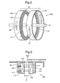
Fig. 3 is a schematic part cross section illustrating the generator parts in hub halves in accordance with the embodiments of aspects of the present invention depicted inFig. 1 ; and, -
Fig. 4 is a schematic perspective view of a second embodiment of an electrical generator in accordance with aspects of the present invention. - Aspects of the present invention provide a means for generating electrical power in a rotating reference frame in the form of a hub. In such circumstances, it is not necessary to transfer the electrical power from a stationary generator to the rotating reference frame. Such an approach will avoid the necessity of slip rings and so considerably improve maintenance, reliability and capability of sustained operation.
- Aspects of the present invention utilise the relatively high differential speeds produced by closely spaced contra-rotating elements in the form of hub halves with a gap between them. These contra-rotating elements are typically a respective first hub half and a second hub half utilised with regard to open rotor or a turbo prop propulsion systems for aircraft.
- Referring to
Figure 1 , a twin-spooled, contra-rotating propeller gas turbine engine is generally indicated at 10 and has a principal androtational axis 9. Theengine 10 comprises acore engine 11 having, in axial flow series, anair intake 12, an intermediate pressure compressor 14 (IPC), a high-pressure compressor 15 (HPC),combustion equipment 16, a high-pressure turbine 17 (HPT), low pressure turbine 18 (IPT), a free power turbine 19 (LPT) and acore exhaust nozzle 20. Anacelle 21 generally surrounds thecore engine 11 and defines theintake 12 andnozzle 20 and acore exhaust duct 22. Theengine 10 also comprises two contra-rotatingpropellers free power turbine 19, which comprises contra-rotatingblade arrays respective hubs - The
gas turbine engine 10 works in a conventional manner so that air entering the intake 13 is accelerated and compressed by the IPC 14 and directed into the HPC 15 where further compression takes place. The compressed air exhausted from the HPC 15 is directed into thecombustion equipment 16 where it is mixed with fuel and the mixture combusted. The resultant hot combustion products then expand through, and thereby drive the high, low-pressure andfree power turbines nozzle 20 to provide some propulsive thrust. The high, low-pressure andfree power turbines intermediate pressure compressors propellers propellers -
Fig. 2 provides a schematic illustration of anelectrical generator 100 in accordance with a first embodiment of the present invention. Thegenerator 100 comprises arotor hub 32 having afirst hub 33 and asecond hub 34. In use therespective halves arrowheads hubs axis 9. There is agap 8 between thehalves arrowheads - In this embodiment, the
electrical generator 100 is incorporated into the contra-rotating propellergas turbine engine 10 ofFig 1 . Therotor hub 32 is configured as part of the contra-rotatingturbine 19, where the contra-rotatinghubs first hub 33 and thesecond hub 34 of thegenerator 100. - Opposed surfaces of the
respective halves generator coil parts 110 and secondgenerator magnet parts 111. As will be described later, the respective first generator parts and second generator parts comprise a generator part pair, comprising a magnet and coil to allow electrical power generation. However, it will be appreciated that a single generator pair comprisingfirst generator parts 110 andsecond generator parts 111 could be provided as a basic configuration in accordance with aspects of the present invention. As illustrated theparts hub first part 110 and asecond part 111 in use in thehubs - The
gap 8 will be set between thehub parts gap 8 may be variable in some circumstances in order to alter electrical power generation by reducing the extent of the electromagnetic interaction between thetransformer parts - Generally, the
first generator parts 110 comprise electrical coils as shown in appropriate positions about the periphery of thehubs second generator parts 111 comprise magnets and most typically permanent magnets in order to avoid electrical power couplings for utilisation of electromagnets in use. However, where such electrical couplings are possible it will be appreciated that the magnets 4 may be electromagnets or it may be possible to provide batteries within thegenerator 100 in order to powerelectromagnets 111 in use. The batteries may be charged when the hub is stationary. However, such an approach is generally contrary to the objective of providing self contained electrical power generation within the rotary frame constituted by therotor 32 without necessity for electrical couplings such as slip rings etc. A further option is to use electromagnets to augment (positively or negatively) the field produced by the permanent magnet to give additional control over the generated voltage. In this arrangement the initial energisation of the electromagnets could be accomplished using the generation capability of the permanent magnets and as the resulting voltage builds, so may the electromagnet's field. - It is by interaction between the first generator parts and the second generator parts that electrical power is generated.
Fig. 3 provides a schematic part cross section of the arrangement 1 depicted inFig. 2 . It will be noted that thegenerator parts appropriate fastenings 120, 121 such that in use despite the high speed rotation of thehubs generator parts gap 8. In such circumstances, the relative rotation of the hub s33, 34 generates an electromagnetic interaction depicted by respectivebroken lines first generator parts 111 and these coils will be connected through electrical wiring to electrical loads such as blade pitch actuators or de-icer mechanisms. - It will be appreciated that the width of the
gap 8 will be significant with regard to electrical power generation. Possibly, the gap will be in the order of 10mm. The closer thegap 8 the greater the electromagnetic interaction but clearly agap 8 of a reasonable extent is required in order to take account of rotational eccentricities ofhubs hubs gap 8 through an appropriate gap adjuster (not shown). Such an approach may allow variations in theelectromagnetic interactions first transformer parts 110. - Generally, the
hubs first part 10 in eachhub second generator part 111 opposite in eachhub - Generally, each
hub first generator parts 110 andsecond generator parts 111. As it is the rotation in cutting across therespective parts such parts respective hub first generator parts 10 andsecond generator parts 111 arranged in a ring or partial ring around a periphery of thehubs respective hub hubs - By providing a
generator 100 as described above, it will be understood that a substantially self contained electrical generator is provided within the rotating reference frame constituted by therotor 32. In such circumstances, it is not necessary to provide an electrical connection from a stationary or static generator through slip rings. - Clearly, space will be a significant factor with regard to acceptability with regard to electrical generators in accordance with aspects of the present invention. By appropriate analysis it is possible to generate within a typical turbo prop or contra rotating arrangement in the order of 500 kW of generation capacity between the two
hubs - As with the first embodiment to the present invention, the second embodiment shown in
Fig 4 comprises theelectrical generator 100 incorporated into the contra-rotating propellergas turbine engine 10 ofFig 1 . Therotor 32 is configured as part of the contra-rotatingturbine 19, as an example, where the contra-rotatinghubs first hub 43 and thesecond hub 44 of thegenerator 100. -
Fig. 4 provides a schematic front perspective view of a second embodiment of the present invention with respect to anelectrical generator 31 in whichrespective hubs arrowheads gap 8 is provided between thehubs hubs first generator parts 40 andsecond generator parts 41 arranged around the periphery of thehubs second generator parts 41 is provided whilst only a small proportion of the peripheral surface of thehubs first generator parts 40. In such circumstances, electrical power generated will be reduced as indicated above to that necessary but more particularly in accordance with this aspect of the present invention the weight of further coils which are unnecessary in thefirst generator part 40 is avoided. In terms of other operation as indicated thehubs common axis 9 and in such circumstances operate in a similar fashion to that described above with regard toFig. 2 and Fig. 3 above. - As indicated above, matching the capacity of the electrical generator in accordance with aspects of the present invention with potential loads in the effectively self contained and isolated generator system has advantages in terms of minimising mass and volume. In such circumstances, consideration of typical loads which may be presented to the electrical generator can be made. These loads, as indicated above, particularly may relate to pitch variation mechanisms and mechanisms for de-icing. The necessary electrical capacity for the generator can be determined by summing all of the potential loads which may be applied. Such an approach will obviously create an electrical generator which for most stages and periods of operation the arrangement has a capacity which is significantly greater than that necessary. To optimise usage consideration of natural diversity factors and thermal gradients as well as thermal inertia will allow potential switching between the loads. For example, as indicated, one load may relate to de-icing and therefore it may be possible to switch off such de-icing functions while the pitch variation actuator is operational. Once the desired pitch for each blade has been achieved the de-icing function can then be resumed. Such an approach will require use of a suitable controller which can oversee such load balancing to ensure that the functional objectives are met whilst safety is not compromised.
- It will be understood that the electrical output from the coils in a generator in accordance with aspects of the present invention will be an alternating current. However, during operation typically the speed of rotation between the respective hub halves will not be constant as there will typically be a different optimised speed for each phase of flight with respect to contra rotating turbo prop arrangements. These changing speeds will clearly alter the frequency of the alternating current output and furthermore, as excitation is via permanent magnets in the preferred embodiment, the output voltage will change with the operating speed. In such circumstances, generally, in accordance with aspects of the present invention the electrical generator will incorporate suitable power conditioning facilities such as for rectification and voltage stabilisation in order to ensure an adequately stable power supply is provided to the loads such as the pitch variation actuators or de-icing mechanism along with associated controls and systems.
- By aspects of the present invention it will be appreciated that an electrical power generator is provided within which electrical power can be generated in a self contained manner within the rotating hub of a contra-rotating aircraft propulsion system. The generator can be made entirely independently and from solid state components and therefore is free from moving parts. It will be appreciated that avoiding soft moving parts which wear will improve reliability. Even though the parts rotate within the rotary frame they are static with respect to other parts of the generator. It will be understood that aspects of the present invention avoid utilisation of sliding contacts which will inherently wear in use and require regular maintenance.
- By utilisation of a multiplicity of permanent magnets for excitation of independent electrical coils it will be understood that the generator in accordance with aspects of the present invention has a high tolerance to faults and therefore is a highly reliable source of electrical power in use.
- Although described with regard to propulsion systems for an aircraft in the example described above, it will also be understood that aspects of the present invention could be utilised with respect to other installations where there are differential speeds developed between elements that rotate in opposite directions in order to effectively double the operating speed of the generator.
- It will be understood that existing differential motion between two separate elements and a common third element such as a shaft may be utilised in order to provide the necessary relative motion and interaction between the generator parts in accordance with aspects of the present invention. For example, where there is a high speed shaft rotating at in the order of 5000rpm that shaft may carry permanent magnets and rotating hubs may carry coils for electrical power generation. These hubs may incorporate power conversion devices and may be driven at a lower speed and in opposite directions to each other. In such a way the relative speed between the relatively slowly rotating hubs as one hub half and the faster rotating drive shaft as the other hub half will enable a more compact design for a given power generation requirement even though it may be necessary to embed such arrangements within other machinery.
- Modifications and alterations to aspects of the present invention will be appreciated by persons skilled in the technology. In such circumstances, as described above, the coils utilised as the first generator parts in accordance with aspects of the present invention may be arranged to be operable only in a proportion of the periphery of the hub half. Nevertheless, several segments may be configured in appropriate pairs such that elective switching into operation of coil segments may be provided to vary the electrical power value generated by a generator in accordance with aspects of the present invention. Furthermore, means for laterally displacing the generator parts and in particular the magnetic second generator parts relative to the first generator parts may be provided in order to adjust interaction and therefore electrical power generation. The number of segments in operation may be dependent upon a centrifugal switch tied to the rotational speeds of the hub.
- As shown in
Fig 1 , the present invention is particularly applicable to a gas turbine engine having contra-rotating rotors and in this exemplary case an open rotor or propeller engine. Nonetheless, other contra rotating compressors and turbines of gas turbines (including aero, industrial, vehicular or marine) may comprise thegenerator 100 of the present invention.
Claims (15)
- A gas turbine engine (10) comprising a contra-rotating rotor (19, 32) incorporating an electrical generator arrangement (100, 31), the rotor (19, 32) arranged to cause in use movement of a first generator part (110, 40) relative to a second generator part (111, 41), the generator characterised in that the rotor (19, 32) comprises a first hub (33, 43) and a second hub (34, 44) arranged in use to rotate in opposite directions with a gap (8) between them, the first generator part in the first hub and the second generator part in the second hub with the second generator part opposite the first generator part across the gap.
- A gas turbine engine (10) as claimed in claim 1 wherein the second generator part is magnetic and the first generator part is an electrical coil.
- A gas turbine engine (10) as claimed in claim 1 or claim 2 wherein the second transformer part is a plurality of permanent magnets.
- A gas turbine engine (10) as claimed in any of claims 1, 2 or 3 wherein each hub of the rotary hub includes a plurality of generator parts.
- A gas turbine engine (10) as claimed in claim 4 wherein the generator parts present each first generator part and each second generator part across the gap with all first generator parts in the first hub and all second generator parts in the second hub.
- A gas turbine engine (10) as claimed in claim 4 wherein the generator parts comprise generator part pairs arranged by opposing a first generator part and a second generator part across the gap with either a first generator part or a second generator part in the first hub opposed with a respective first generator part or second generator part in the second hub.
- A gas turbine engine (10) as claimed in claim 4 and any claim dependent thereon wherein the generator parts in the same hub are concentric with each other with a respective first generator part and second generator part opposite each other in the respective first hub and the second hub part of the rotor.
- A gas turbine engine (10) as claimed in any preceding claim wherein the generator parts extend fully or partially around the periphery of the first hub and the second hub.
- A gas turbine engine (10) as claimed in any preceding claim wherein each hub, in terms of generator parts, is identical, except with regard to configuration of the transformer part on each hub to interact with the corresponding magnets on the other hub.
- A gas turbine engine (10) as claimed in any preceding claim wherein the generator is associated with a plurality of electrical loads comprising any one or more of the group actuators for blade pitch, a de-icer mechanism, and a gas turbine engine system.
- A gas turbine engine (10) as claimed in claim 10 wherein a switch is provided to allow switching between the electrical loads.
- A gas turbine engine (10) as claimed in any preceding claim wherein the generator is associated with an electrical power conditioner mechanism.
- A gas turbine engine (10) as claimed in claim 13 wherein the power conditioner mechanism incorporates an electrical rectifier and/or means for electrical power stabilisation.
- A gas turbine engine (10) as claimed in any preceding claim wherein the hubs are separately driven by a drive mechanism to cause relative motion between the hubs.
- A gas turbine engine (10) as claimed in any of claims 1 to 13 wherein the hubs are associated with a driven member which incorporates one or both of the generator parts opposed by a respective generator part in the hub.
Applications Claiming Priority (1)
| Application Number | Priority Date | Filing Date | Title |
|---|---|---|---|
| GBGB0809247.0A GB0809247D0 (en) | 2008-05-22 | 2008-05-22 | An electrical generator arrangement |
Publications (3)
| Publication Number | Publication Date |
|---|---|
| EP2128403A2 true EP2128403A2 (en) | 2009-12-02 |
| EP2128403A3 EP2128403A3 (en) | 2017-07-26 |
| EP2128403B1 EP2128403B1 (en) | 2018-06-27 |
Family
ID=39596273
Family Applications (1)
| Application Number | Title | Priority Date | Filing Date |
|---|---|---|---|
| EP09251121.1A Not-in-force EP2128403B1 (en) | 2008-05-22 | 2009-04-17 | An electrical generator arrangement for a gas turbine |
Country Status (4)
| Country | Link |
|---|---|
| US (1) | US8008822B2 (en) |
| EP (1) | EP2128403B1 (en) |
| JP (1) | JP2009281385A (en) |
| GB (1) | GB0809247D0 (en) |
Cited By (4)
| Publication number | Priority date | Publication date | Assignee | Title |
|---|---|---|---|---|
| FR2961176A1 (en) * | 2010-06-15 | 2011-12-16 | Hispano Suiza Sa | ELECTRICAL SUPPLY OF EQUIPMENT FITTED BY THE ROTOR OF AN AIRCRAFT ENGINE |
| GB2467208B (en) * | 2009-01-23 | 2013-02-27 | Snecma | Turbine engine with a power turbine equipped with an electric power generator centered on the axis of the turbine engine. |
| WO2013138837A3 (en) * | 2012-03-22 | 2013-11-14 | Sima Ewald | Embodiments of electric-magnetic-mechanical machines having rotors with interacting magnetic forces and the use thereof |
| EP3691091A1 (en) * | 2019-01-31 | 2020-08-05 | General Electric Company | Dual rotor electric machine |
Families Citing this family (33)
| Publication number | Priority date | Publication date | Assignee | Title |
|---|---|---|---|---|
| US8294316B2 (en) * | 2009-07-28 | 2012-10-23 | Rolls-Royce North American Technologies, Inc. | Electrical power generation apparatus for contra-rotating open-rotor aircraft propulsion system |
| US8063528B2 (en) * | 2009-12-18 | 2011-11-22 | General Electric Company | Counter-rotatable generator |
| GB201007063D0 (en) * | 2010-04-28 | 2010-06-09 | Rolls Royce Plc | A gas turbine engine |
| US8522522B2 (en) * | 2010-07-30 | 2013-09-03 | Hamilton Sundstrand Corporation | Fan embedded power generator |
| MY164491A (en) * | 2010-09-03 | 2017-12-29 | Winpro Co Ltd | Disk-shaped coaxial inversion generator and wind driven generating equipment including the same |
| US8701381B2 (en) | 2010-11-24 | 2014-04-22 | Rolls-Royce Corporation | Remote shaft driven open rotor propulsion system with electrical power generation |
| GB201110640D0 (en) * | 2011-06-23 | 2011-08-10 | Rolls Royce Plc | An electrical machine with contra-rotating rotors |
| US8464511B1 (en) * | 2012-01-06 | 2013-06-18 | Hamilton Sundstrand Corporation | Magnetically coupled contra-rotating propulsion stages |
| CN102787961A (en) * | 2012-06-28 | 2012-11-21 | 万成高 | Tail water and tail gas generating device |
| US8907512B2 (en) | 2012-11-20 | 2014-12-09 | Turbogen, Llc | Load apparatus and method of using same |
| US8796875B2 (en) | 2012-11-20 | 2014-08-05 | Turbogen, Llc | Housing apparatus for use with an electrical system and method of using same |
| EP3929406B1 (en) | 2013-03-15 | 2024-05-22 | RTX Corporation | De-icing by integral electric heat generation |
| WO2014150377A1 (en) * | 2013-03-15 | 2014-09-25 | Embry-Riddle Aeronautical University, Inc. | Electrically coupled counter-rotation for gas turbine compressors |
| US10243424B2 (en) * | 2013-04-18 | 2019-03-26 | Oeco, Llp | Mast-mounted aircraft generator |
| US9556624B1 (en) | 2014-06-27 | 2017-01-31 | Utility Service Co., Inc. | Scaffold system |
| US9973058B2 (en) | 2014-07-23 | 2018-05-15 | Hamilton Sundstrand Corporation | Propeller in-hub power generation and control |
| US10116187B1 (en) * | 2015-10-02 | 2018-10-30 | Cr Flight Llc | Thin-profile counter-rotating differential electric motor assembly |
| US10071811B2 (en) * | 2016-08-22 | 2018-09-11 | General Electric Company | Embedded electric machine |
| US10312781B2 (en) | 2016-10-05 | 2019-06-04 | Rolls-Royce North American Technologies, Inc. | Multiple coil electric generator in turbine engine |
| US10513986B2 (en) | 2016-10-05 | 2019-12-24 | Rolls-Royce North American Technologies, Inc. | Counter-rotating electric generator in turbine engine |
| US10737801B2 (en) * | 2016-10-31 | 2020-08-11 | Rolls-Royce Corporation | Fan module with rotatable vane ring power system |
| US10618667B2 (en) | 2016-10-31 | 2020-04-14 | Rolls-Royce Corporation | Fan module with adjustable pitch blades and power system |
| US11148784B2 (en) * | 2017-03-31 | 2021-10-19 | Alluvionic, Inc. | Propeller system with directional thrust control |
| GB201807770D0 (en) * | 2018-05-14 | 2018-06-27 | Rolls Royce Plc | Electric ducted fan |
| GB201807769D0 (en) * | 2018-05-14 | 2018-06-27 | Rolls Royce Plc | Electric ducted fan |
| US11156128B2 (en) | 2018-08-22 | 2021-10-26 | General Electric Company | Embedded electric machine |
| CN111509934B (en) * | 2019-01-31 | 2023-05-05 | 通用电气公司 | double rotor motor |
| GB201902095D0 (en) * | 2019-02-15 | 2019-04-03 | Rolls Royce Plc | Electric turbomachine |
| US11362567B2 (en) | 2020-01-16 | 2022-06-14 | The Boeing Company | Electrical power generation from turbine engines |
| CN114762229B (en) * | 2020-01-17 | 2026-04-14 | 小鹰公司 | Non-reaction free-turning motor with double propellers |
| JP2021180579A (en) | 2020-05-14 | 2021-11-18 | 国立大学法人東京海洋大学 | Radial gap type synchronous machine and motor power generation system |
| CN113123871B (en) * | 2021-04-21 | 2022-04-22 | 南京航空航天大学 | Jet self-driven and blade tip turbine driven contra-rotating propeller fan engine with hoop |
| US12149154B2 (en) | 2021-07-22 | 2024-11-19 | General Electric Company | Electric machine having a hybrid insulative-conductive manifold |
Family Cites Families (18)
| Publication number | Priority date | Publication date | Assignee | Title |
|---|---|---|---|---|
| US279476A (en) * | 1883-06-12 | Dynamo electric machine | ||
| US889883A (en) * | 1907-08-31 | 1908-06-02 | Emil J Johnson | Wind-operated dynamo. |
| US1163501A (en) * | 1914-08-17 | 1915-12-07 | Gustav W Eisenhohr | Electric generator. |
| US1530376A (en) * | 1921-08-15 | 1925-03-17 | Krawinkel Gunther | High-frequency machine |
| US1787930A (en) * | 1929-04-20 | 1931-01-06 | William D Fletcher | Apparatus for generating electric energy |
| GB585556A (en) | 1945-03-01 | 1947-02-11 | Fairey Aviat Co Ltd | Improvements in or relating to means for preventing the formation of ice on rotatable parts of aircraft |
| GB603438A (en) | 1945-05-07 | 1948-06-16 | Fairey Aviat Co Ltd | Improvements in or relating to electrical equipment on aircraft |
| GB603450A (en) | 1945-07-03 | 1948-06-16 | Fairey Aviat Co Ltd | Improvements in or relating to electrical equipment on aircraft |
| US2896143A (en) * | 1957-03-11 | 1959-07-21 | Genisco Inc | Electric drive assembly |
| NL7213122A (en) * | 1971-10-04 | 1973-04-06 | ||
| DE2248571A1 (en) | 1972-10-04 | 1974-04-11 | Walter Schoenball | RINGDYNAMO / RING GENERATOR WIND POWER PLANT |
| US4556366A (en) | 1983-10-17 | 1985-12-03 | General Electric Company | Propeller actuation system |
| US4927329A (en) * | 1988-10-21 | 1990-05-22 | General Electric Company | Aircraft engine unducted fan blade pitch control system |
| US5376827A (en) * | 1993-05-27 | 1994-12-27 | General Electric Company | Integrated turbine-generator |
| DE4444757A1 (en) | 1994-12-15 | 1996-06-20 | Lehmann Klaus Dieter | Wind-powered generator/blower arrangement |
| GB2402976B (en) | 2003-06-05 | 2006-09-27 | Intec Power Systems Ltd | Generator |
| GB0313456D0 (en) * | 2003-06-11 | 2003-07-16 | Rolls Royce Plc | Propulsion arrangement |
| US7453180B2 (en) * | 2003-11-25 | 2008-11-18 | General Atomics | Rotary disk energy storage and pulse power supply |
-
2008
- 2008-05-22 GB GBGB0809247.0A patent/GB0809247D0/en not_active Ceased
-
2009
- 2009-04-17 EP EP09251121.1A patent/EP2128403B1/en not_active Not-in-force
- 2009-04-21 US US12/385,827 patent/US8008822B2/en active Active
- 2009-05-21 JP JP2009123239A patent/JP2009281385A/en not_active Ceased
Cited By (8)
| Publication number | Priority date | Publication date | Assignee | Title |
|---|---|---|---|---|
| GB2467208B (en) * | 2009-01-23 | 2013-02-27 | Snecma | Turbine engine with a power turbine equipped with an electric power generator centered on the axis of the turbine engine. |
| FR2961176A1 (en) * | 2010-06-15 | 2011-12-16 | Hispano Suiza Sa | ELECTRICAL SUPPLY OF EQUIPMENT FITTED BY THE ROTOR OF AN AIRCRAFT ENGINE |
| WO2011157924A1 (en) * | 2010-06-15 | 2011-12-22 | Hispano-Suiza | Electric power supply for apparatuses supported by the rotor of an aircraft engine |
| JP2013531579A (en) * | 2010-06-15 | 2013-08-08 | イスパノ・シユイザ | Power supply to equipment supported by aircraft engine rotors |
| US9458729B2 (en) | 2010-06-15 | 2016-10-04 | Labinal Power Systems | Electric power supply for apparatuses supported by the rotor of an aircraft engine |
| WO2013138837A3 (en) * | 2012-03-22 | 2013-11-14 | Sima Ewald | Embodiments of electric-magnetic-mechanical machines having rotors with interacting magnetic forces and the use thereof |
| EP3691091A1 (en) * | 2019-01-31 | 2020-08-05 | General Electric Company | Dual rotor electric machine |
| US11735988B2 (en) | 2019-01-31 | 2023-08-22 | General Electric Company | Dual rotor electric machine |
Also Published As
| Publication number | Publication date |
|---|---|
| JP2009281385A (en) | 2009-12-03 |
| US8008822B2 (en) | 2011-08-30 |
| GB0809247D0 (en) | 2008-06-25 |
| EP2128403A3 (en) | 2017-07-26 |
| US20090289516A1 (en) | 2009-11-26 |
| EP2128403B1 (en) | 2018-06-27 |
Similar Documents
| Publication | Publication Date | Title |
|---|---|---|
| US8008822B2 (en) | Electrical generator arrangement | |
| EP2613033B1 (en) | Magnetically coupled contra-rotating propulsion stages | |
| US6767187B2 (en) | Electrohydraulic device for varying the pitch of the blades of a machine rotor | |
| US20200309027A1 (en) | Gas turbine engine with an electromagnetic transmission | |
| US10240477B2 (en) | Turbofan engine with generator | |
| US6914344B2 (en) | Integrated starter/generator for a turbomachine | |
| US8198744B2 (en) | Integrated boost cavity ring generator for turbofan and turboshaft engines | |
| US20200227966A1 (en) | Turbomachine | |
| US20160160867A1 (en) | Electrically coupled counter-rotation for gas turbine compressors | |
| EP2977314B1 (en) | Propeller in-hub power generation and control | |
| US11905890B2 (en) | Differential gearbox assembly for a turbine engine | |
| US9963981B2 (en) | Pitch change mechanism for shrouded fan with low fan pressure ratio | |
| CA2736795A1 (en) | Accessory gearbox with a starter/generator | |
| US20070169462A1 (en) | Gas turbine, especially an aircraft engine | |
| WO2014196975A1 (en) | Jet engine assembly and method for generating electricity | |
| EP3690199A1 (en) | De-icing system for vanes of a gas turbine engine and corresponding de-icing method | |
| US20140260323A1 (en) | Gas turbine engine and active balancing system | |
| US10731504B2 (en) | Device for controlling inlet guide vanes by means of a multilayer piezoelectric actuator | |
| US20220364508A1 (en) | System for vibration management in rotating machinery | |
| EP4462655A1 (en) | Electrical energy system having active segments for variable voltage generation | |
| US20250389202A1 (en) | Gas turbine-driven shared-rotor electric generator | |
| CN121794453A (en) | Including turbines for driving permanent magnet motors for rotating loads. | |
| EP4023558A1 (en) | Aeronautical propulsion device |
Legal Events
| Date | Code | Title | Description |
|---|---|---|---|
| PUAI | Public reference made under article 153(3) epc to a published international application that has entered the european phase |
Free format text: ORIGINAL CODE: 0009012 |
|
| AK | Designated contracting states |
Kind code of ref document: A2 Designated state(s): AT BE BG CH CY CZ DE DK EE ES FI FR GB GR HR HU IE IS IT LI LT LU LV MC MK MT NL NO PL PT RO SE SI SK TR |
|
| RAP1 | Party data changed (applicant data changed or rights of an application transferred) |
Owner name: ROLLS-ROYCE PLC |
|
| PUAL | Search report despatched |
Free format text: ORIGINAL CODE: 0009013 |
|
| AK | Designated contracting states |
Kind code of ref document: A3 Designated state(s): AT BE BG CH CY CZ DE DK EE ES FI FR GB GR HR HU IE IS IT LI LT LU LV MC MK MT NL NO PL PT RO SE SI SK TR |
|
| AX | Request for extension of the european patent |
Extension state: AL BA RS |
|
| RIC1 | Information provided on ipc code assigned before grant |
Ipc: F02C 7/32 20060101AFI20170622BHEP Ipc: F01D 15/10 20060101ALI20170622BHEP |
|
| STAA | Information on the status of an ep patent application or granted ep patent |
Free format text: STATUS: REQUEST FOR EXAMINATION WAS MADE |
|
| 17P | Request for examination filed |
Effective date: 20180111 |
|
| GRAP | Despatch of communication of intention to grant a patent |
Free format text: ORIGINAL CODE: EPIDOSNIGR1 |
|
| STAA | Information on the status of an ep patent application or granted ep patent |
Free format text: STATUS: GRANT OF PATENT IS INTENDED |
|
| INTG | Intention to grant announced |
Effective date: 20180328 |
|
| GRAS | Grant fee paid |
Free format text: ORIGINAL CODE: EPIDOSNIGR3 |
|
| GRAA | (expected) grant |
Free format text: ORIGINAL CODE: 0009210 |
|
| STAA | Information on the status of an ep patent application or granted ep patent |
Free format text: STATUS: THE PATENT HAS BEEN GRANTED |
|
| AK | Designated contracting states |
Kind code of ref document: B1 Designated state(s): AT BE BG CH CY CZ DE DK EE ES FI FR GB GR HR HU IE IS IT LI LT LU LV MC MK MT NL NO PL PT RO SE SI SK TR |
|
| REG | Reference to a national code |
Ref country code: GB Ref legal event code: FG4D |
|
| REG | Reference to a national code |
Ref country code: AT Ref legal event code: REF Ref document number: 1012560 Country of ref document: AT Kind code of ref document: T Effective date: 20180715 |
|
| REG | Reference to a national code |
Ref country code: IE Ref legal event code: FG4D |
|
| REG | Reference to a national code |
Ref country code: DE Ref legal event code: R096 Ref document number: 602009052925 Country of ref document: DE |
|
| PG25 | Lapsed in a contracting state [announced via postgrant information from national office to epo] |
Ref country code: FI Free format text: LAPSE BECAUSE OF FAILURE TO SUBMIT A TRANSLATION OF THE DESCRIPTION OR TO PAY THE FEE WITHIN THE PRESCRIBED TIME-LIMIT Effective date: 20180627 Ref country code: LT Free format text: LAPSE BECAUSE OF FAILURE TO SUBMIT A TRANSLATION OF THE DESCRIPTION OR TO PAY THE FEE WITHIN THE PRESCRIBED TIME-LIMIT Effective date: 20180627 Ref country code: BG Free format text: LAPSE BECAUSE OF FAILURE TO SUBMIT A TRANSLATION OF THE DESCRIPTION OR TO PAY THE FEE WITHIN THE PRESCRIBED TIME-LIMIT Effective date: 20180927 Ref country code: SE Free format text: LAPSE BECAUSE OF FAILURE TO SUBMIT A TRANSLATION OF THE DESCRIPTION OR TO PAY THE FEE WITHIN THE PRESCRIBED TIME-LIMIT Effective date: 20180627 Ref country code: NO Free format text: LAPSE BECAUSE OF FAILURE TO SUBMIT A TRANSLATION OF THE DESCRIPTION OR TO PAY THE FEE WITHIN THE PRESCRIBED TIME-LIMIT Effective date: 20180927 |
|
| REG | Reference to a national code |
Ref country code: NL Ref legal event code: MP Effective date: 20180627 |
|
| REG | Reference to a national code |
Ref country code: LT Ref legal event code: MG4D |
|
| PG25 | Lapsed in a contracting state [announced via postgrant information from national office to epo] |
Ref country code: GR Free format text: LAPSE BECAUSE OF FAILURE TO SUBMIT A TRANSLATION OF THE DESCRIPTION OR TO PAY THE FEE WITHIN THE PRESCRIBED TIME-LIMIT Effective date: 20180928 Ref country code: HR Free format text: LAPSE BECAUSE OF FAILURE TO SUBMIT A TRANSLATION OF THE DESCRIPTION OR TO PAY THE FEE WITHIN THE PRESCRIBED TIME-LIMIT Effective date: 20180627 Ref country code: LV Free format text: LAPSE BECAUSE OF FAILURE TO SUBMIT A TRANSLATION OF THE DESCRIPTION OR TO PAY THE FEE WITHIN THE PRESCRIBED TIME-LIMIT Effective date: 20180627 |
|
| REG | Reference to a national code |
Ref country code: AT Ref legal event code: MK05 Ref document number: 1012560 Country of ref document: AT Kind code of ref document: T Effective date: 20180627 |
|
| PG25 | Lapsed in a contracting state [announced via postgrant information from national office to epo] |
Ref country code: NL Free format text: LAPSE BECAUSE OF FAILURE TO SUBMIT A TRANSLATION OF THE DESCRIPTION OR TO PAY THE FEE WITHIN THE PRESCRIBED TIME-LIMIT Effective date: 20180627 |
|
| PG25 | Lapsed in a contracting state [announced via postgrant information from national office to epo] |
Ref country code: IS Free format text: LAPSE BECAUSE OF FAILURE TO SUBMIT A TRANSLATION OF THE DESCRIPTION OR TO PAY THE FEE WITHIN THE PRESCRIBED TIME-LIMIT Effective date: 20181027 Ref country code: EE Free format text: LAPSE BECAUSE OF FAILURE TO SUBMIT A TRANSLATION OF THE DESCRIPTION OR TO PAY THE FEE WITHIN THE PRESCRIBED TIME-LIMIT Effective date: 20180627 Ref country code: AT Free format text: LAPSE BECAUSE OF FAILURE TO SUBMIT A TRANSLATION OF THE DESCRIPTION OR TO PAY THE FEE WITHIN THE PRESCRIBED TIME-LIMIT Effective date: 20180627 Ref country code: CZ Free format text: LAPSE BECAUSE OF FAILURE TO SUBMIT A TRANSLATION OF THE DESCRIPTION OR TO PAY THE FEE WITHIN THE PRESCRIBED TIME-LIMIT Effective date: 20180627 Ref country code: SK Free format text: LAPSE BECAUSE OF FAILURE TO SUBMIT A TRANSLATION OF THE DESCRIPTION OR TO PAY THE FEE WITHIN THE PRESCRIBED TIME-LIMIT Effective date: 20180627 Ref country code: RO Free format text: LAPSE BECAUSE OF FAILURE TO SUBMIT A TRANSLATION OF THE DESCRIPTION OR TO PAY THE FEE WITHIN THE PRESCRIBED TIME-LIMIT Effective date: 20180627 Ref country code: PL Free format text: LAPSE BECAUSE OF FAILURE TO SUBMIT A TRANSLATION OF THE DESCRIPTION OR TO PAY THE FEE WITHIN THE PRESCRIBED TIME-LIMIT Effective date: 20180627 |
|
| PG25 | Lapsed in a contracting state [announced via postgrant information from national office to epo] |
Ref country code: IT Free format text: LAPSE BECAUSE OF FAILURE TO SUBMIT A TRANSLATION OF THE DESCRIPTION OR TO PAY THE FEE WITHIN THE PRESCRIBED TIME-LIMIT Effective date: 20180627 Ref country code: ES Free format text: LAPSE BECAUSE OF FAILURE TO SUBMIT A TRANSLATION OF THE DESCRIPTION OR TO PAY THE FEE WITHIN THE PRESCRIBED TIME-LIMIT Effective date: 20180627 |
|
| REG | Reference to a national code |
Ref country code: DE Ref legal event code: R097 Ref document number: 602009052925 Country of ref document: DE |
|
| PLBE | No opposition filed within time limit |
Free format text: ORIGINAL CODE: 0009261 |
|
| STAA | Information on the status of an ep patent application or granted ep patent |
Free format text: STATUS: NO OPPOSITION FILED WITHIN TIME LIMIT |
|
| PG25 | Lapsed in a contracting state [announced via postgrant information from national office to epo] |
Ref country code: DK Free format text: LAPSE BECAUSE OF FAILURE TO SUBMIT A TRANSLATION OF THE DESCRIPTION OR TO PAY THE FEE WITHIN THE PRESCRIBED TIME-LIMIT Effective date: 20180627 |
|
| 26N | No opposition filed |
Effective date: 20190328 |
|
| PG25 | Lapsed in a contracting state [announced via postgrant information from national office to epo] |
Ref country code: SI Free format text: LAPSE BECAUSE OF FAILURE TO SUBMIT A TRANSLATION OF THE DESCRIPTION OR TO PAY THE FEE WITHIN THE PRESCRIBED TIME-LIMIT Effective date: 20180627 |
|
| REG | Reference to a national code |
Ref country code: CH Ref legal event code: PL |
|
| REG | Reference to a national code |
Ref country code: BE Ref legal event code: MM Effective date: 20190430 |
|
| PG25 | Lapsed in a contracting state [announced via postgrant information from national office to epo] |
Ref country code: LU Free format text: LAPSE BECAUSE OF NON-PAYMENT OF DUE FEES Effective date: 20190417 Ref country code: MC Free format text: LAPSE BECAUSE OF FAILURE TO SUBMIT A TRANSLATION OF THE DESCRIPTION OR TO PAY THE FEE WITHIN THE PRESCRIBED TIME-LIMIT Effective date: 20180627 |
|
| PG25 | Lapsed in a contracting state [announced via postgrant information from national office to epo] |
Ref country code: LI Free format text: LAPSE BECAUSE OF NON-PAYMENT OF DUE FEES Effective date: 20190430 Ref country code: CH Free format text: LAPSE BECAUSE OF NON-PAYMENT OF DUE FEES Effective date: 20190430 |
|
| PG25 | Lapsed in a contracting state [announced via postgrant information from national office to epo] |
Ref country code: BE Free format text: LAPSE BECAUSE OF NON-PAYMENT OF DUE FEES Effective date: 20190430 |
|
| PG25 | Lapsed in a contracting state [announced via postgrant information from national office to epo] |
Ref country code: TR Free format text: LAPSE BECAUSE OF FAILURE TO SUBMIT A TRANSLATION OF THE DESCRIPTION OR TO PAY THE FEE WITHIN THE PRESCRIBED TIME-LIMIT Effective date: 20180627 |
|
| PG25 | Lapsed in a contracting state [announced via postgrant information from national office to epo] |
Ref country code: IE Free format text: LAPSE BECAUSE OF NON-PAYMENT OF DUE FEES Effective date: 20190417 |
|
| PG25 | Lapsed in a contracting state [announced via postgrant information from national office to epo] |
Ref country code: PT Free format text: LAPSE BECAUSE OF FAILURE TO SUBMIT A TRANSLATION OF THE DESCRIPTION OR TO PAY THE FEE WITHIN THE PRESCRIBED TIME-LIMIT Effective date: 20181029 |
|
| PG25 | Lapsed in a contracting state [announced via postgrant information from national office to epo] |
Ref country code: CY Free format text: LAPSE BECAUSE OF FAILURE TO SUBMIT A TRANSLATION OF THE DESCRIPTION OR TO PAY THE FEE WITHIN THE PRESCRIBED TIME-LIMIT Effective date: 20180627 |
|
| PG25 | Lapsed in a contracting state [announced via postgrant information from national office to epo] |
Ref country code: HU Free format text: LAPSE BECAUSE OF FAILURE TO SUBMIT A TRANSLATION OF THE DESCRIPTION OR TO PAY THE FEE WITHIN THE PRESCRIBED TIME-LIMIT; INVALID AB INITIO Effective date: 20090417 Ref country code: MT Free format text: LAPSE BECAUSE OF FAILURE TO SUBMIT A TRANSLATION OF THE DESCRIPTION OR TO PAY THE FEE WITHIN THE PRESCRIBED TIME-LIMIT Effective date: 20180627 |
|
| PG25 | Lapsed in a contracting state [announced via postgrant information from national office to epo] |
Ref country code: MK Free format text: LAPSE BECAUSE OF FAILURE TO SUBMIT A TRANSLATION OF THE DESCRIPTION OR TO PAY THE FEE WITHIN THE PRESCRIBED TIME-LIMIT Effective date: 20180627 |
|
| P01 | Opt-out of the competence of the unified patent court (upc) registered |
Effective date: 20230528 |
|
| PGFP | Annual fee paid to national office [announced via postgrant information from national office to epo] |
Ref country code: FR Payment date: 20230421 Year of fee payment: 15 Ref country code: DE Payment date: 20230427 Year of fee payment: 15 |
|
| PGFP | Annual fee paid to national office [announced via postgrant information from national office to epo] |
Ref country code: GB Payment date: 20230418 Year of fee payment: 15 |
|
| REG | Reference to a national code |
Ref country code: DE Ref legal event code: R119 Ref document number: 602009052925 Country of ref document: DE |
|
| GBPC | Gb: european patent ceased through non-payment of renewal fee |
Effective date: 20240417 |
|
| PG25 | Lapsed in a contracting state [announced via postgrant information from national office to epo] |
Ref country code: DE Free format text: LAPSE BECAUSE OF NON-PAYMENT OF DUE FEES Effective date: 20241105 |
|
| PG25 | Lapsed in a contracting state [announced via postgrant information from national office to epo] |
Ref country code: GB Free format text: LAPSE BECAUSE OF NON-PAYMENT OF DUE FEES Effective date: 20240417 |
|
| PG25 | Lapsed in a contracting state [announced via postgrant information from national office to epo] |
Ref country code: FR Free format text: LAPSE BECAUSE OF NON-PAYMENT OF DUE FEES Effective date: 20240430 |
|
| PG25 | Lapsed in a contracting state [announced via postgrant information from national office to epo] |
Ref country code: GB Free format text: LAPSE BECAUSE OF NON-PAYMENT OF DUE FEES Effective date: 20240417 Ref country code: FR Free format text: LAPSE BECAUSE OF NON-PAYMENT OF DUE FEES Effective date: 20240430 Ref country code: DE Free format text: LAPSE BECAUSE OF NON-PAYMENT OF DUE FEES Effective date: 20241105 |