EP2127842A1 - Process for production of solid products having depressions on the surface - Google Patents
Process for production of solid products having depressions on the surface Download PDFInfo
- Publication number
- EP2127842A1 EP2127842A1 EP07713808A EP07713808A EP2127842A1 EP 2127842 A1 EP2127842 A1 EP 2127842A1 EP 07713808 A EP07713808 A EP 07713808A EP 07713808 A EP07713808 A EP 07713808A EP 2127842 A1 EP2127842 A1 EP 2127842A1
- Authority
- EP
- European Patent Office
- Prior art keywords
- solvent
- solution
- solid body
- parts
- producing
- Prior art date
- Legal status (The legal status is an assumption and is not a legal conclusion. Google has not performed a legal analysis and makes no representation as to the accuracy of the status listed.)
- Granted
Links
- 238000000034 method Methods 0.000 title claims abstract description 35
- 238000004519 manufacturing process Methods 0.000 title description 14
- 239000012265 solid product Substances 0.000 title 1
- 239000002904 solvent Substances 0.000 claims abstract description 188
- 230000000994 depressogenic effect Effects 0.000 claims abstract description 39
- 229920000642 polymer Polymers 0.000 claims abstract description 39
- 150000001875 compounds Chemical class 0.000 claims abstract description 35
- 239000007787 solid Substances 0.000 claims abstract description 29
- 238000009835 boiling Methods 0.000 claims abstract description 25
- 238000009833 condensation Methods 0.000 claims abstract description 19
- 230000005494 condensation Effects 0.000 claims abstract description 19
- 230000002209 hydrophobic effect Effects 0.000 claims abstract description 15
- 238000001704 evaporation Methods 0.000 claims abstract description 11
- 239000004431 polycarbonate resin Substances 0.000 claims description 39
- 229920005668 polycarbonate resin Polymers 0.000 claims description 39
- MVPPADPHJFYWMZ-UHFFFAOYSA-N chlorobenzene Chemical compound ClC1=CC=CC=C1 MVPPADPHJFYWMZ-UHFFFAOYSA-N 0.000 claims description 27
- YXFVVABEGXRONW-UHFFFAOYSA-N Toluene Chemical compound CC1=CC=CC=C1 YXFVVABEGXRONW-UHFFFAOYSA-N 0.000 claims description 17
- IAZDPXIOMUYVGZ-UHFFFAOYSA-N Dimethylsulphoxide Chemical compound CS(C)=O IAZDPXIOMUYVGZ-UHFFFAOYSA-N 0.000 claims description 16
- ZMXDDKWLCZADIW-UHFFFAOYSA-N N,N-Dimethylformamide Chemical compound CN(C)C=O ZMXDDKWLCZADIW-UHFFFAOYSA-N 0.000 claims description 12
- 238000004776 molecular orbital Methods 0.000 claims description 11
- 238000004364 calculation method Methods 0.000 claims description 10
- SECXISVLQFMRJM-UHFFFAOYSA-N N-Methylpyrrolidone Chemical compound CN1CCCC1=O SECXISVLQFMRJM-UHFFFAOYSA-N 0.000 claims description 8
- AUHZEENZYGFFBQ-UHFFFAOYSA-N 1,3,5-trimethylbenzene Chemical compound CC1=CC(C)=CC(C)=C1 AUHZEENZYGFFBQ-UHFFFAOYSA-N 0.000 claims description 6
- CTQNGGLPUBDAKN-UHFFFAOYSA-N O-Xylene Chemical compound CC1=CC=CC=C1C CTQNGGLPUBDAKN-UHFFFAOYSA-N 0.000 claims description 6
- URLKBWYHVLBVBO-UHFFFAOYSA-N Para-Xylene Chemical compound CC1=CC=C(C)C=C1 URLKBWYHVLBVBO-UHFFFAOYSA-N 0.000 claims description 6
- IVSZLXZYQVIEFR-UHFFFAOYSA-N m-xylene Chemical compound CC1=CC=CC(C)=C1 IVSZLXZYQVIEFR-UHFFFAOYSA-N 0.000 claims description 6
- 238000005457 optimization Methods 0.000 claims description 6
- KMTRUDSVKNLOMY-UHFFFAOYSA-N Ethylene carbonate Chemical compound O=C1OCCO1 KMTRUDSVKNLOMY-UHFFFAOYSA-N 0.000 claims description 5
- SZXQTJUDPRGNJN-UHFFFAOYSA-N dipropylene glycol Chemical compound OCCCOCCCO SZXQTJUDPRGNJN-UHFFFAOYSA-N 0.000 claims description 5
- ZIBGPFATKBEMQZ-UHFFFAOYSA-N triethylene glycol Chemical compound OCCOCCOCCO ZIBGPFATKBEMQZ-UHFFFAOYSA-N 0.000 claims description 5
- SBASXUCJHJRPEV-UHFFFAOYSA-N 2-(2-methoxyethoxy)ethanol Chemical compound COCCOCCO SBASXUCJHJRPEV-UHFFFAOYSA-N 0.000 claims description 4
- POAOYUHQDCAZBD-UHFFFAOYSA-N 2-butoxyethanol Chemical compound CCCCOCCO POAOYUHQDCAZBD-UHFFFAOYSA-N 0.000 claims description 4
- FXHOOIRPVKKKFG-UHFFFAOYSA-N N,N-Dimethylacetamide Chemical compound CN(C)C(C)=O FXHOOIRPVKKKFG-UHFFFAOYSA-N 0.000 claims description 4
- XXJWXESWEXIICW-UHFFFAOYSA-N diethylene glycol monoethyl ether Chemical compound CCOCCOCCO XXJWXESWEXIICW-UHFFFAOYSA-N 0.000 claims description 4
- 229940075557 diethylene glycol monoethyl ether Drugs 0.000 claims description 4
- 229920001225 polyester resin Polymers 0.000 claims description 4
- 239000004645 polyester resin Substances 0.000 claims description 4
- HNJBEVLQSNELDL-UHFFFAOYSA-N pyrrolidin-2-one Chemical compound O=C1CCCN1 HNJBEVLQSNELDL-UHFFFAOYSA-N 0.000 claims description 4
- SUAKHGWARZSWIH-UHFFFAOYSA-N N,N‐diethylformamide Chemical compound CCN(CC)C=O SUAKHGWARZSWIH-UHFFFAOYSA-N 0.000 claims description 3
- 239000002635 aromatic organic solvent Substances 0.000 claims description 3
- 125000003118 aryl group Chemical group 0.000 claims description 3
- RUOJZAUFBMNUDX-UHFFFAOYSA-N propylene carbonate Chemical compound CC1COC(=O)O1 RUOJZAUFBMNUDX-UHFFFAOYSA-N 0.000 claims description 3
- HXJUTPCZVOIRIF-UHFFFAOYSA-N sulfolane Chemical compound O=S1(=O)CCCC1 HXJUTPCZVOIRIF-UHFFFAOYSA-N 0.000 claims description 3
- 229940113088 dimethylacetamide Drugs 0.000 claims description 2
- 239000000243 solution Substances 0.000 description 86
- 229920005989 resin Polymers 0.000 description 74
- 239000011347 resin Substances 0.000 description 74
- 239000011521 glass Substances 0.000 description 54
- XLYOFNOQVPJJNP-UHFFFAOYSA-N water Substances O XLYOFNOQVPJJNP-UHFFFAOYSA-N 0.000 description 42
- 238000002156 mixing Methods 0.000 description 26
- 229920001230 polyarylate Polymers 0.000 description 25
- 239000011148 porous material Substances 0.000 description 24
- 238000010438 heat treatment Methods 0.000 description 23
- 238000005259 measurement Methods 0.000 description 22
- KKEYFWRCBNTPAC-UHFFFAOYSA-N Terephthalic acid Chemical compound OC(=O)C1=CC=C(C(O)=O)C=C1 KKEYFWRCBNTPAC-UHFFFAOYSA-N 0.000 description 16
- QQVIHTHCMHWDBS-UHFFFAOYSA-N isophthalic acid Chemical compound OC(=O)C1=CC=CC(C(O)=O)=C1 QQVIHTHCMHWDBS-UHFFFAOYSA-N 0.000 description 16
- 239000000126 substance Substances 0.000 description 16
- 239000004420 Iupilon Substances 0.000 description 12
- 239000000203 mixture Substances 0.000 description 12
- 239000004713 Cyclic olefin copolymer Substances 0.000 description 11
- 229920000089 Cyclic olefin copolymer Polymers 0.000 description 10
- XDTMQSROBMDMFD-UHFFFAOYSA-N Cyclohexane Chemical compound C1CCCCC1 XDTMQSROBMDMFD-UHFFFAOYSA-N 0.000 description 9
- -1 Monochlorobenzene Dimethoxymethane Chemical compound 0.000 description 9
- 239000000463 material Substances 0.000 description 9
- YMWUJEATGCHHMB-UHFFFAOYSA-N Dichloromethane Chemical compound ClCCl YMWUJEATGCHHMB-UHFFFAOYSA-N 0.000 description 8
- 230000000052 comparative effect Effects 0.000 description 8
- 239000000758 substrate Substances 0.000 description 8
- 239000008346 aqueous phase Substances 0.000 description 7
- 239000012528 membrane Substances 0.000 description 7
- NKDDWNXOKDWJAK-UHFFFAOYSA-N dimethoxymethane Chemical group COCOC NKDDWNXOKDWJAK-UHFFFAOYSA-N 0.000 description 6
- WKBPZYKAUNRMKP-UHFFFAOYSA-N 1-[2-(2,4-dichlorophenyl)pentyl]1,2,4-triazole Chemical compound C=1C=C(Cl)C=C(Cl)C=1C(CCC)CN1C=NC=N1 WKBPZYKAUNRMKP-UHFFFAOYSA-N 0.000 description 5
- 239000001089 [(2R)-oxolan-2-yl]methanol Substances 0.000 description 5
- BSYVTEYKTMYBMK-UHFFFAOYSA-N tetrahydrofurfuryl alcohol Chemical compound OCC1CCCO1 BSYVTEYKTMYBMK-UHFFFAOYSA-N 0.000 description 5
- SVTBMSDMJJWYQN-UHFFFAOYSA-N 2-methylpentane-2,4-diol Chemical compound CC(O)CC(C)(C)O SVTBMSDMJJWYQN-UHFFFAOYSA-N 0.000 description 4
- KWYHDKDOAIKMQN-UHFFFAOYSA-N N,N,N',N'-tetramethylethylenediamine Chemical compound CN(C)CCN(C)C KWYHDKDOAIKMQN-UHFFFAOYSA-N 0.000 description 4
- 229940113120 dipropylene glycol Drugs 0.000 description 4
- 238000002474 experimental method Methods 0.000 description 4
- 239000003960 organic solvent Substances 0.000 description 4
- 230000001737 promoting effect Effects 0.000 description 4
- 230000005428 wave function Effects 0.000 description 4
- OISVCGZHLKNMSJ-UHFFFAOYSA-N 2,6-dimethylpyridine Chemical compound CC1=CC=CC(C)=N1 OISVCGZHLKNMSJ-UHFFFAOYSA-N 0.000 description 3
- 0 CN(CCN1*)C1=C Chemical compound CN(CCN1*)C1=C 0.000 description 3
- ZHNUHDYFZUAESO-UHFFFAOYSA-N Formamide Chemical compound NC=O ZHNUHDYFZUAESO-UHFFFAOYSA-N 0.000 description 3
- PEDCQBHIVMGVHV-UHFFFAOYSA-N Glycerine Chemical compound OCC(O)CO PEDCQBHIVMGVHV-UHFFFAOYSA-N 0.000 description 3
- IMNFDUFMRHMDMM-UHFFFAOYSA-N N-Heptane Chemical compound CCCCCCC IMNFDUFMRHMDMM-UHFFFAOYSA-N 0.000 description 3
- 238000007664 blowing Methods 0.000 description 3
- 239000011248 coating agent Substances 0.000 description 3
- 238000000576 coating method Methods 0.000 description 3
- 238000001816 cooling Methods 0.000 description 3
- MTHSVFCYNBDYFN-UHFFFAOYSA-N diethylene glycol Chemical compound OCCOCCO MTHSVFCYNBDYFN-UHFFFAOYSA-N 0.000 description 3
- 230000000694 effects Effects 0.000 description 3
- 238000007747 plating Methods 0.000 description 3
- 239000002344 surface layer Substances 0.000 description 3
- PUPZLCDOIYMWBV-UHFFFAOYSA-N (+/-)-1,3-Butanediol Chemical compound CC(O)CCO PUPZLCDOIYMWBV-UHFFFAOYSA-N 0.000 description 2
- AVQQQNCBBIEMEU-UHFFFAOYSA-N 1,1,3,3-tetramethylurea Chemical compound CN(C)C(=O)N(C)C AVQQQNCBBIEMEU-UHFFFAOYSA-N 0.000 description 2
- RRQYJINTUHWNHW-UHFFFAOYSA-N 1-ethoxy-2-(2-ethoxyethoxy)ethane Chemical compound CCOCCOCCOCC RRQYJINTUHWNHW-UHFFFAOYSA-N 0.000 description 2
- JYYNAJVZFGKDEQ-UHFFFAOYSA-N 2,4-Dimethylpyridine Chemical compound CC1=CC=NC(C)=C1 JYYNAJVZFGKDEQ-UHFFFAOYSA-N 0.000 description 2
- XLLIQLLCWZCATF-UHFFFAOYSA-N 2-methoxyethyl acetate Chemical compound COCCOC(C)=O XLLIQLLCWZCATF-UHFFFAOYSA-N 0.000 description 2
- YEJRWHAVMIAJKC-UHFFFAOYSA-N 4-Butyrolactone Chemical compound O=C1CCCO1 YEJRWHAVMIAJKC-UHFFFAOYSA-N 0.000 description 2
- FKNQCJSGGFJEIZ-UHFFFAOYSA-N 4-methylpyridine Chemical compound CC1=CC=NC=C1 FKNQCJSGGFJEIZ-UHFFFAOYSA-N 0.000 description 2
- FERIUCNNQQJTOY-UHFFFAOYSA-N Butyric acid Chemical compound CCCC(O)=O FERIUCNNQQJTOY-UHFFFAOYSA-N 0.000 description 2
- OFBQJSOFQDEBGM-UHFFFAOYSA-N Pentane Chemical compound CCCCC OFBQJSOFQDEBGM-UHFFFAOYSA-N 0.000 description 2
- ALQSHHUCVQOPAS-UHFFFAOYSA-N Pentane-1,5-diol Chemical compound OCCCCCO ALQSHHUCVQOPAS-UHFFFAOYSA-N 0.000 description 2
- SMWDFEZZVXVKRB-UHFFFAOYSA-N Quinoline Chemical compound N1=CC=CC2=CC=CC=C21 SMWDFEZZVXVKRB-UHFFFAOYSA-N 0.000 description 2
- PPBRXRYQALVLMV-UHFFFAOYSA-N Styrene Chemical compound C=CC1=CC=CC=C1 PPBRXRYQALVLMV-UHFFFAOYSA-N 0.000 description 2
- WYURNTSHIVDZCO-UHFFFAOYSA-N Tetrahydrofuran Chemical compound C1CCOC1 WYURNTSHIVDZCO-UHFFFAOYSA-N 0.000 description 2
- KOXIVMUITVOLHH-UHFFFAOYSA-N chlorobenzene methylsulfinylmethane Chemical compound ClC1=CC=CC=C1.CS(=O)C KOXIVMUITVOLHH-UHFFFAOYSA-N 0.000 description 2
- SWXVUIWOUIDPGS-UHFFFAOYSA-N diacetone alcohol Chemical compound CC(=O)CC(C)(C)O SWXVUIWOUIDPGS-UHFFFAOYSA-N 0.000 description 2
- 229940019778 diethylene glycol diethyl ether Drugs 0.000 description 2
- XBDQKXXYIPTUBI-UHFFFAOYSA-N dimethylselenoniopropionate Natural products CCC(O)=O XBDQKXXYIPTUBI-UHFFFAOYSA-N 0.000 description 2
- 239000010419 fine particle Substances 0.000 description 2
- VLKZOEOYAKHREP-UHFFFAOYSA-N n-Hexane Chemical compound CCCCCC VLKZOEOYAKHREP-UHFFFAOYSA-N 0.000 description 2
- 229940113115 polyethylene glycol 200 Drugs 0.000 description 2
- DNIAPMSPPWPWGF-GSVOUGTGSA-N (R)-(-)-Propylene glycol Chemical compound C[C@@H](O)CO DNIAPMSPPWPWGF-GSVOUGTGSA-N 0.000 description 1
- MAUMSNABMVEOGP-UHFFFAOYSA-N (methyl-$l^{2}-azanyl)methane Chemical compound C[N]C MAUMSNABMVEOGP-UHFFFAOYSA-N 0.000 description 1
- ZWVMLYRJXORSEP-UHFFFAOYSA-N 1,2,6-Hexanetriol Chemical compound OCCCCC(O)CO ZWVMLYRJXORSEP-UHFFFAOYSA-N 0.000 description 1
- CYSGHNMQYZDMIA-UHFFFAOYSA-N 1,3-Dimethyl-2-imidazolidinon Chemical compound CN1CCN(C)C1=O CYSGHNMQYZDMIA-UHFFFAOYSA-N 0.000 description 1
- QWOZZTWBWQMEPD-UHFFFAOYSA-N 1-(2-ethoxypropoxy)propan-2-ol Chemical compound CCOC(C)COCC(C)O QWOZZTWBWQMEPD-UHFFFAOYSA-N 0.000 description 1
- JOLQKTGDSGKSKJ-UHFFFAOYSA-N 1-ethoxypropan-2-ol Chemical compound CCOCC(C)O JOLQKTGDSGKSKJ-UHFFFAOYSA-N 0.000 description 1
- KMZHZAAOEWVPSE-UHFFFAOYSA-N 2,3-dihydroxypropyl acetate Chemical compound CC(=O)OCC(O)CO KMZHZAAOEWVPSE-UHFFFAOYSA-N 0.000 description 1
- FPZWZCWUIYYYBU-UHFFFAOYSA-N 2-(2-ethoxyethoxy)ethyl acetate Chemical compound CCOCCOCCOC(C)=O FPZWZCWUIYYYBU-UHFFFAOYSA-N 0.000 description 1
- FMVOPJLFZGSYOS-UHFFFAOYSA-N 2-[2-(2-ethoxypropoxy)propoxy]propan-1-ol Chemical compound CCOC(C)COC(C)COC(C)CO FMVOPJLFZGSYOS-UHFFFAOYSA-N 0.000 description 1
- GVNHOISKXMSMPX-UHFFFAOYSA-N 2-[butyl(2-hydroxyethyl)amino]ethanol Chemical compound CCCCN(CCO)CCO GVNHOISKXMSMPX-UHFFFAOYSA-N 0.000 description 1
- ZNQVEEAIQZEUHB-UHFFFAOYSA-N 2-ethoxyethanol Chemical compound CCOCCO ZNQVEEAIQZEUHB-UHFFFAOYSA-N 0.000 description 1
- 229940093475 2-ethoxyethanol Drugs 0.000 description 1
- XWKFPIODWVPXLX-UHFFFAOYSA-N 2-methyl-5-methylpyridine Natural products CC1=CC=C(C)N=C1 XWKFPIODWVPXLX-UHFFFAOYSA-N 0.000 description 1
- QCAHUFWKIQLBNB-UHFFFAOYSA-N 3-(3-methoxypropoxy)propan-1-ol Chemical compound COCCCOCCCO QCAHUFWKIQLBNB-UHFFFAOYSA-N 0.000 description 1
- SSZWWUDQMAHNAQ-UHFFFAOYSA-N 3-chloropropane-1,2-diol Chemical compound OCC(O)CCl SSZWWUDQMAHNAQ-UHFFFAOYSA-N 0.000 description 1
- ITQTTZVARXURQS-UHFFFAOYSA-N 3-methylpyridine Chemical compound CC1=CC=CN=C1 ITQTTZVARXURQS-UHFFFAOYSA-N 0.000 description 1
- 239000004925 Acrylic resin Substances 0.000 description 1
- 229920000178 Acrylic resin Polymers 0.000 description 1
- WLTDYZNLDKNMLM-UHFFFAOYSA-N CCCC1C(CC2)CC2C1C Chemical compound CCCC1C(CC2)CC2C1C WLTDYZNLDKNMLM-UHFFFAOYSA-N 0.000 description 1
- HEDRZPFGACZZDS-UHFFFAOYSA-N Chloroform Chemical compound ClC(Cl)Cl HEDRZPFGACZZDS-UHFFFAOYSA-N 0.000 description 1
- DAMHJWNXYOSPHL-UHFFFAOYSA-N ClC1=CC=CC=C1.C(CCC)OCCO Chemical compound ClC1=CC=CC=C1.C(CCC)OCCO DAMHJWNXYOSPHL-UHFFFAOYSA-N 0.000 description 1
- 239000004641 Diallyl-phthalate Substances 0.000 description 1
- 239000004348 Glyceryl diacetate Substances 0.000 description 1
- 238000004957 LCAO calculation Methods 0.000 description 1
- 239000004721 Polyphenylene oxide Substances 0.000 description 1
- 241000053208 Porcellio laevis Species 0.000 description 1
- XUIMIQQOPSSXEZ-UHFFFAOYSA-N Silicon Chemical compound [Si] XUIMIQQOPSSXEZ-UHFFFAOYSA-N 0.000 description 1
- GSEJCLTVZPLZKY-UHFFFAOYSA-N Triethanolamine Chemical compound OCCN(CCO)CCO GSEJCLTVZPLZKY-UHFFFAOYSA-N 0.000 description 1
- 229920006311 Urethane elastomer Polymers 0.000 description 1
- 239000012814 acoustic material Substances 0.000 description 1
- 239000003463 adsorbent Substances 0.000 description 1
- 229920000180 alkyd Polymers 0.000 description 1
- 239000004599 antimicrobial Substances 0.000 description 1
- 239000012298 atmosphere Substances 0.000 description 1
- QUDWYFHPNIMBFC-UHFFFAOYSA-N bis(prop-2-enyl) benzene-1,2-dicarboxylate Chemical compound C=CCOC(=O)C1=CC=CC=C1C(=O)OCC=C QUDWYFHPNIMBFC-UHFFFAOYSA-N 0.000 description 1
- 238000005266 casting Methods 0.000 description 1
- 239000003054 catalyst Substances 0.000 description 1
- VBZLMUUEMHVOMQ-UHFFFAOYSA-N chlorobenzene N,N-dimethylacetamide Chemical compound CC(=O)N(C)C.ClC1=CC=CC=C1 VBZLMUUEMHVOMQ-UHFFFAOYSA-N 0.000 description 1
- VVRBGMKQGBCMNL-UHFFFAOYSA-N chlorobenzene;1-methylpyrrolidin-2-one Chemical compound CN1CCCC1=O.ClC1=CC=CC=C1 VVRBGMKQGBCMNL-UHFFFAOYSA-N 0.000 description 1
- DRBUOMRBZPMETF-UHFFFAOYSA-N chlorobenzene;n,n-dimethylformamide Chemical compound CN(C)C=O.ClC1=CC=CC=C1 DRBUOMRBZPMETF-UHFFFAOYSA-N 0.000 description 1
- 239000004020 conductor Substances 0.000 description 1
- 239000003431 cross linking reagent Substances 0.000 description 1
- 230000007547 defect Effects 0.000 description 1
- 239000003989 dielectric material Substances 0.000 description 1
- SBZXBUIDTXKZTM-UHFFFAOYSA-N diglyme Chemical compound COCCOCCOC SBZXBUIDTXKZTM-UHFFFAOYSA-N 0.000 description 1
- 238000003618 dip coating Methods 0.000 description 1
- 238000001035 drying Methods 0.000 description 1
- 229920001971 elastomer Polymers 0.000 description 1
- 239000003822 epoxy resin Substances 0.000 description 1
- 230000008020 evaporation Effects 0.000 description 1
- 238000012617 force field calculation Methods 0.000 description 1
- 239000002783 friction material Substances 0.000 description 1
- 235000019443 glyceryl diacetate Nutrition 0.000 description 1
- GNOIPBMMFNIUFM-UHFFFAOYSA-N hexamethylphosphoric triamide Chemical compound CN(C)P(=O)(N(C)C)N(C)C GNOIPBMMFNIUFM-UHFFFAOYSA-N 0.000 description 1
- CBOIHMRHGLHBPB-UHFFFAOYSA-N hydroxymethyl Chemical compound O[CH2] CBOIHMRHGLHBPB-UHFFFAOYSA-N 0.000 description 1
- 239000012774 insulation material Substances 0.000 description 1
- 239000012567 medical material Substances 0.000 description 1
- 239000002184 metal Substances 0.000 description 1
- 239000000113 methacrylic resin Substances 0.000 description 1
- 239000011259 mixed solution Substances 0.000 description 1
- 238000012986 modification Methods 0.000 description 1
- 230000004048 modification Effects 0.000 description 1
- 238000004219 molecular orbital method Methods 0.000 description 1
- DNIAPMSPPWPWGF-UHFFFAOYSA-N monopropylene glycol Natural products CC(O)CO DNIAPMSPPWPWGF-UHFFFAOYSA-N 0.000 description 1
- 239000004014 plasticizer Substances 0.000 description 1
- 229920002285 poly(styrene-co-acrylonitrile) Polymers 0.000 description 1
- 229920002492 poly(sulfone) Polymers 0.000 description 1
- 229920000647 polyepoxide Polymers 0.000 description 1
- 229920001223 polyethylene glycol Polymers 0.000 description 1
- 229920006380 polyphenylene oxide Polymers 0.000 description 1
- 229920005749 polyurethane resin Polymers 0.000 description 1
- 235000019260 propionic acid Nutrition 0.000 description 1
- 235000013772 propylene glycol Nutrition 0.000 description 1
- IUVKMZGDUIUOCP-BTNSXGMBSA-N quinbolone Chemical compound O([C@H]1CC[C@H]2[C@H]3[C@@H]([C@]4(C=CC(=O)C=C4CC3)C)CC[C@@]21C)C1=CCCC1 IUVKMZGDUIUOCP-BTNSXGMBSA-N 0.000 description 1
- 230000002940 repellent Effects 0.000 description 1
- 239000005871 repellent Substances 0.000 description 1
- 238000001338 self-assembly Methods 0.000 description 1
- 238000000926 separation method Methods 0.000 description 1
- 229910052710 silicon Inorganic materials 0.000 description 1
- 239000010703 silicon Substances 0.000 description 1
- 238000004528 spin coating Methods 0.000 description 1
- UWHCKJMYHZGTIT-UHFFFAOYSA-N tetraethylene glycol Chemical compound OCCOCCOCCOCCO UWHCKJMYHZGTIT-UHFFFAOYSA-N 0.000 description 1
- YLQBMQCUIZJEEH-UHFFFAOYSA-N tetrahydrofuran Natural products C=1C=COC=1 YLQBMQCUIZJEEH-UHFFFAOYSA-N 0.000 description 1
- 125000003944 tolyl group Chemical group 0.000 description 1
- DQWPFSLDHJDLRL-UHFFFAOYSA-N triethyl phosphate Chemical compound CCOP(=O)(OCC)OCC DQWPFSLDHJDLRL-UHFFFAOYSA-N 0.000 description 1
Images



Classifications
-
- B—PERFORMING OPERATIONS; TRANSPORTING
- B29—WORKING OF PLASTICS; WORKING OF SUBSTANCES IN A PLASTIC STATE IN GENERAL
- B29C—SHAPING OR JOINING OF PLASTICS; SHAPING OF MATERIAL IN A PLASTIC STATE, NOT OTHERWISE PROVIDED FOR; AFTER-TREATMENT OF THE SHAPED PRODUCTS, e.g. REPAIRING
- B29C41/00—Shaping by coating a mould, core or other substrate, i.e. by depositing material and stripping-off the shaped article; Apparatus therefor
- B29C41/02—Shaping by coating a mould, core or other substrate, i.e. by depositing material and stripping-off the shaped article; Apparatus therefor for making articles of definite length, i.e. discrete articles
-
- C—CHEMISTRY; METALLURGY
- C09—DYES; PAINTS; POLISHES; NATURAL RESINS; ADHESIVES; COMPOSITIONS NOT OTHERWISE PROVIDED FOR; APPLICATIONS OF MATERIALS NOT OTHERWISE PROVIDED FOR
- C09D—COATING COMPOSITIONS, e.g. PAINTS, VARNISHES OR LACQUERS; FILLING PASTES; CHEMICAL PAINT OR INK REMOVERS; INKS; CORRECTING FLUIDS; WOODSTAINS; PASTES OR SOLIDS FOR COLOURING OR PRINTING; USE OF MATERIALS THEREFOR
- C09D169/00—Coating compositions based on polycarbonates; Coating compositions based on derivatives of polycarbonates
-
- C—CHEMISTRY; METALLURGY
- C08—ORGANIC MACROMOLECULAR COMPOUNDS; THEIR PREPARATION OR CHEMICAL WORKING-UP; COMPOSITIONS BASED THEREON
- C08J—WORKING-UP; GENERAL PROCESSES OF COMPOUNDING; AFTER-TREATMENT NOT COVERED BY SUBCLASSES C08B, C08C, C08F, C08G or C08H
- C08J9/00—Working-up of macromolecular substances to porous or cellular articles or materials; After-treatment thereof
- C08J9/28—Working-up of macromolecular substances to porous or cellular articles or materials; After-treatment thereof by elimination of a liquid phase from a macromolecular composition or article, e.g. drying of coagulum
-
- C—CHEMISTRY; METALLURGY
- C09—DYES; PAINTS; POLISHES; NATURAL RESINS; ADHESIVES; COMPOSITIONS NOT OTHERWISE PROVIDED FOR; APPLICATIONS OF MATERIALS NOT OTHERWISE PROVIDED FOR
- C09D—COATING COMPOSITIONS, e.g. PAINTS, VARNISHES OR LACQUERS; FILLING PASTES; CHEMICAL PAINT OR INK REMOVERS; INKS; CORRECTING FLUIDS; WOODSTAINS; PASTES OR SOLIDS FOR COLOURING OR PRINTING; USE OF MATERIALS THEREFOR
- C09D167/00—Coating compositions based on polyesters obtained by reactions forming a carboxylic ester link in the main chain; Coating compositions based on derivatives of such polymers
- C09D167/02—Polyesters derived from dicarboxylic acids and dihydroxy compounds
- C09D167/03—Polyesters derived from dicarboxylic acids and dihydroxy compounds the dicarboxylic acids and dihydroxy compounds having the carboxyl - and the hydroxy groups directly linked to aromatic rings
-
- C—CHEMISTRY; METALLURGY
- C09—DYES; PAINTS; POLISHES; NATURAL RESINS; ADHESIVES; COMPOSITIONS NOT OTHERWISE PROVIDED FOR; APPLICATIONS OF MATERIALS NOT OTHERWISE PROVIDED FOR
- C09D—COATING COMPOSITIONS, e.g. PAINTS, VARNISHES OR LACQUERS; FILLING PASTES; CHEMICAL PAINT OR INK REMOVERS; INKS; CORRECTING FLUIDS; WOODSTAINS; PASTES OR SOLIDS FOR COLOURING OR PRINTING; USE OF MATERIALS THEREFOR
- C09D5/00—Coating compositions, e.g. paints, varnishes or lacquers, characterised by their physical nature or the effects produced; Filling pastes
- C09D5/28—Coating compositions, e.g. paints, varnishes or lacquers, characterised by their physical nature or the effects produced; Filling pastes for wrinkle, crackle, orange-peel, or similar decorative effects
Definitions
- the present invention relates to a method of producing a solid body having a depressed portion on a surface. More specifically, the present invention relates to a method of producing a solid body having a surface formed with a depressed portion by self assembly from selection of a specific solution composition.
- Japanese Patent Application Laid-Open No. H01-268733 discloses a method of producing a porous membrane having uses in a filter or the like by condensation fine droplets on a substrate, coating the substrate with a membrane material solution that is immiscible with the fine droplets and drying the thus-formed substrate.
- Japanese Patent Application Laid-Open No. H08-311231 discloses a method of producing a porous body having a honeycomb structure by coating a cooled polymer solution to condense vapor in the atmosphere on the coated surface.
- Japanese Patent Laid-Open Nos. 2001-157574 and 2002-335949 disclose a method of producing a porous body having a honeycomb structure by casting a hydrophobic organic solvent solution of a biodegradable, amphiphilic polymer to condense droplets on the cast solution surface. This porous body is expected to be used in applications in the medical field.
- the present invention is characterized by using a solution at least comprising a solvent A, a solvent B and a polymer compound soluble in solvent B, solvent A being a hydrophilic solvent and solvent B being a hydrophobic solvent, the boiling point of solvent A being equal to or higher than the boiling point of solvent B, and the total mass of solvent B being 50% or more of the total mass of the solvents contained in the solution, and solidifying the solution while forming an depressed portion from condensation on the surface of the solution during a process wherein either one or both of the solvent A and solvent B contained in the solution are evaporating.
- a very inexpensive and stable method for producing a solid body having a depressed portion on a surface is provided. Especially in the case where a specific solution composition has been selected, it is possible to provide a production method in which a depressed portion on a surface can be self-assembled, or more specifically, a surface shape can be formed without any other controls, just by evaporating the solvent under normal temperature and humidity conditions.
- the "solid body" having a depressed portion on a surface which is produced according to the present invention may be used in a variety of industrial fields, capable of being used as, for example, a separation membrane, an adsorbent, a catalyst, a carrier, a battery member, a medical material, a lightweight structural material, a cushioning material, an insulation material, an acoustic material, vibration restrained material, an electrically conductive material, a piezoelectric material, a friction material, a slidable material and a low-dielectric material.
- hydrophilic solvent refers to a solvent which exhibits a large affinity with water
- hydrophobic solvent refers to a solvent which exhibits a small affinity with water
- the solvent is classified as hydrophilic. In cases where the volume of the aqueous phase is 45 ml or more to 50 ml or less, the solvent is classified as hydrophobic. In cases of a uniform monophase, the volume of the aqueous phase is 0, and the solvent is classified as being hydrophilic. In cases beyond these ranges, the solvent is not classified as either being hydrophilic or hydrophobic.
- the solvent is toluene, for example, the volume of the aqueous phase is 50 ml, and thus is classified as hydrophobic. If the solvent is dimethyl sulfoxide (DMSO), a monophase is formed, and thus the volume of the aqueous phase is 0 ml. In this case, the solvent is classified as hydrophilic. Further, if the solvent is 1,1-dimethoxymethane (methylal), the volume of the aqueous phase is 69 ml, and thus the solvent is not classified as either hydrophilic or hydrophobic.
- DMSO dimethyl sulfoxide
- the expression "dipole moment as calculated from geometry optimization based on a semiempirical molecular-orbital calculation” refers to the value of the dipole moment calculated based on the semiempirical molecular orbital calculation program MOPAC using PM3 parameters.
- a wave function used in the Schroedinger's equation is approximated by the Slater type matricial equation or Gauss type matricial equation consisting of a molecular orbital expressed as a linear combination of atomic orbitals, and the molecular orbital constituting the wave function is found by the use of approximation of field, whereby various physical quantities can be calculated as the total energy, the wave function or as expected values of the wave function.
- Semiempirical molecular-orbital calculation is a method which, when determining a molecular orbital from a field approximation, shortens the calculation time through approximation using parameters in which various actual experiment values are employed whose integral calculations took time to calculate.
- the calculations in the present invention were calculated based on the semiempirical molecular orbital calculation program MOPAC using PM3 parameters as semiempirical parameters.
- the chemical modeling software Cerius2 is used for dipole moment calculation.
- the molecular structure of the solvent to be calculated is produced using the Sketching function of the Cerius2.
- the force-field of this molecular structure is calculated using the Dreding 2.21 program to calculate the charge using the Charge function.
- the structure is then corrected based on a molecular force field calculation using the Minimizer.
- PM3 parameters, Geometry Optimization and Dipole are specified in the MOPAC93 program, and corrected structure and dipole moment are calculated for the thus-obtained structure.
- the affinity between the solvent and water is related to dipole moment.
- a hydrophilic solvent tends to have a large dipole moment, while a hydrophobic solvent tends to have a small dipole moment.
- the tendency is for the hydrophilic solvent A to preferably have a large dipole moment, and the hydrophobic solvent B to preferably have a small dipole moment.
- solvent A and solvent B are respectively shown in the following Tables 1 and 2. However, the solvents A and B according to the present invention are not limited to these examples.
- the term "dipole moment" in Tables 1 and 2 refers to the dipole moment value as calculated in accordance with the above-described method. Further, as a rule, "boiling point” in Tables 1 and 2 refers to the boiling point at atmospheric pressure. In cases where it does not refer to atmospheric pressure, the pressure is clearly specified.
- Table 1 Representative examples of solvent A No.
- solvent A examples include dimethyl sulfoxide, sulfolane, ethylene carbonate, propylene carbonate, dimethyl formamide, diethyl formamide, dimethyl acetamide, 2-butoxyethanol, 2-pyrrolidone, N-methyl-2-pyrrolidone, diethylene glycol monomethyl ether, diethylene glycol monoethyl ether, triethylene glycol and dipropylene glycol.
- solvent B examples include aromatic organic solvents.
- solvents may be used alone, or in combination of two or more thereof. Further, in terms of production stability, solvent A and solvent B preferably have affinity with each other and form a uniform solution; specifically, they are compatible with each other.
- the polymer compound which is soluble in solvent B according to the present invention can be variously selected without restriction depending on the functional properties required in the solid body to be obtained as a product, as long as it is soluble in solvent B.
- preferable examples would include acrylic resin, methacrylic resin, styrene resin, styrene-acrylonitrile copolymer resin, polyester resin, polycarbonate resin, polyarylate resin, polysulfone resin, polyphenyleneoxide resin, epoxy resin, polyurethane resin, alkyd resin, unsaturated resins, conductive resins, aromatic polyester resins and diallylphthalate resin.
- a polycarbonate resin or aromatic polyester resin is especially preferable.
- These polymer compounds may be used alone, or in combination of two or more thereof.
- the production method according to the present invention forms a depressed portion from condensation on a surface of a solution during the process of evaporating the solvent in a solution which comprises the above-described solvent A, solvent B, and polymer compound which is soluble in solvent B.
- condensation refers to water vapor in the air condensing on the solution surface and/or in the solution.
- the solid body having a depressed portion includes the solid body having a depressed portion only on the surface, the solid body in which pores on the surface is penetrated, and the solid body in which many pores are also present in interior of the solid body.
- Commonly-known methods to promote the condensation of water on the surface of a hydrophobic organic solvent solution of a polymer compound include: promoting condensation by cooling the hydrophobic organic solvent solution of a polymer compound; using a highly volatile organic solvent such as dichloromethane to promote condensation by utilizing the cooling effect from evaporation; promoting condensation by controlling the surrounding environment at a high humidity; promoting condensation by blowing a high-humidity gas; or promoting condensation by controlling the solute in which a special amphiphilic polymer is utilized.
- the production method according to the present invention is characterized in that condensation is promoted by using a hydrophilic solvent A for the solvent of the above-described solution, and controlling the solvent system of the above-described solution.
- the present invention has the advantages that: the shape and the depth of the depressed portion formed on the surface of the solid body by condensation can be controlled in accordance with the kind and amount of solvent A, or by the combination thereof; costs can be reduced by utilizing a general-purpose solvent; production stability is excellent as a result of the production method being simple; versatility is excellent because no special production equipment is necessary; and the range of applications is broad.
- the solvent A boiling point must be equal to or higher than the solvent B boiling point. If this is not the case, the solvent A will evaporate before the depressed portion can be stably formed by condensation, or condensation water will boil off along with solvent A, whereby the depressed portion might not be able to be formed.
- the total mass of the hydrophobic solvent B has to be 50% or more of the total mass of the solvents contained in the above-described solution in order to form the depressed portion from condensation on the surface of the solid body. If this range is not satisfied, it may be difficult to form the depressed portion from condensation.
- the boiling point of the solvent with the highest composition ratio among such solvents becomes the "solvent A boiling point”.
- the boiling point of the solvent with the highest composition ratio among such solvents becomes the "solvent B boiling point”.
- the above-described solution can be treated in a variety of different ways depending on the functional properties required in the solid body to be obtained as a product.
- the surface layer can be coated onto the substrate by a well-known method such as dip coating or spin coating, to form the surface layer having a depressed portion.
- a thin membrane or film can be fabricated by peeling off a film formed on the substrate by these same methods from the substrate.
- a thin membrane or film can be fabricated by flowing the above-described solution over a water surface.
- various compounds may be added to the solution for the purpose of conferring functionality to the solid body to be obtained as a product, such as a plasticizer, crosslinking agent, metal fine particles, organic fine particles, electrically conductive compound, antimicrobial agent or the like.
- the kind or amount of solvent A and solvent B may be varied or two or more kinds of solvent can be used together in order to control of the solution viscosity, dew point or overall coated surface smoothness, modify the dissolving power of the solvent system of the solution, or control the size and depth of the pores in the product.
- various solvents other than solvent A and solvent B may be used. It is also possible to combine the step of modifying the temperature of the solution, the temperature of the substrate over which the solution flows, and the humidity of the surrounding environment, and the step of blowing a high-humidity gas onto the surface of the solution.
- a solution was prepared by mixing together and dissolving 6 parts of dimethyl sulfoxide as solvent A, 54 parts of monochlorobenzene as solvent B and 12 parts of polycarbonate resin ("Iupilon Z200", manufactured by Mitsubishi Gas Chemical Company, Inc.) as the polymer compound.
- this solution was coated onto a glass plate under normal temperature and humidity conditions (23°C, 50% RH). Then, while evaporating the solvent by leaving the glass plate for 10 minutes under normal temperature and humidity conditions, a depressed portion was formed on the coated film surface. The glass plate was then dried by heating for 1 hour at 150°C to form a polycarbonate resin film on the glass plate.
- a solution was prepared, without using any solvent A, by mixing together and dissolving 60 parts of monochlorobenzene and 12 parts of polycarbonate resin ("Iupilon Z200", manufactured by Mitsubishi Gas Chemical Company, Inc.). Next, this solution was coated onto a glass plate under normal temperature and humidity conditions (23°C, 50% RH). Then, the solvent was made to evaporate by leaving the glass plate for 10 minutes under normal temperature and humidity conditions. The glass plate was then dried by heating for 1 hour at 150°C to form a polycarbonate resin film on the glass plate. Observation of this resin film in the same manner as in Example 1 with a laser microscope ("VK-9500", manufactured by Keyence Corporation) showed that depressed portions were not formed. The contact angle with water of the thus-formed resin film was measured at 75°. The friction coefficient was measured to be 1.2. These results are shown in Table 3-3.
- a solution was prepared by mixing together and dissolving 1.8 parts of dimethyl sulfoxide as solvent A, 58.2 parts of monochlorobenzene as solvent B and 12 parts of polycarbonate resin ("Iupilon Z200", manufactured by Mitsubishi Gas Chemical Company, Inc.) as the polymer compound.
- the solution was coated onto a glass plate and left to stand, then dried by heating to form a polycarbonate resin film.
- the surface state was observed, and the contact angle with water and the friction coefficient were measured. The results of the contact angle and friction coefficient measurements are shown in Table 3-1. Further, a plurality of pores were regularly formed on the surface of the resin film. The pore diameter was about 6 ⁇ m, and the depth was about 4 ⁇ m.
- a solution was prepared by mixing together and dissolving 9 parts of N,N-dimethylformamide as solvent A, 51 parts of monochlorobenzene as solvent B and 12 parts of polycarbonate resin ("Iupilon Z200", manufactured by Mitsubishi Gas Chemical Company, Inc.) as the polymer compound.
- this solution was coated onto a glass plate under normal temperature and humidity conditions (23°C, 50% RH).
- a depressed portion was formed on the coated film surface, and a polycarbonate resin film was formed on the glass plate.
- the surface state of this resin was observed, and the contact angle with water and the friction coefficient were measured. The observed results of the surface are shown in Figure 9 , and the results of the contact angle and friction coefficient measurements are shown in Table 3-1.
- a solution was prepared by mixing together and dissolving 9 parts of N,N-dimethylacetamide as solvent A, 51 parts of monochlorobenzene as solvent B and 12 parts of polycarbonate resin ("Iupilon Z200", manufactured by Mitsubishi Gas Chemical Company, Inc.) as the polymer compound.
- this solution was coated onto a glass plate under normal temperature and humidity conditions (23°C, 50% RH).
- a depressed portion was formed on the coated film surface, and a polycarbonate resin film was formed on the glass plate.
- the surface state of this resin was observed, and the contact angle with water and the friction coefficient were measured. The observed results of the surface are shown in Figure 10 , and the results of the contact angle and friction coefficient measurements are shown in Table 3-1.
- a solution was prepared by mixing together and dissolving 6 parts of ethylene carbonate as solvent A, 48 parts of monochlorobenzene as solvent B, 6 parts of dimethoxymethane as another solvent and 12 parts of polycarbonate resin ("Iupilon Z200", manufactured by Mitsubishi Gas Chemical Company, Inc.) as the polymer compound.
- the solution was coated onto a glass plate and left to stand, then dried by heating to form a polycarbonate resin film.
- the surface state was observed, and the contact angle with water and the friction coefficient were measured. A plurality of pores were formed on the surface of the resin film. The results of the contact angle and friction coefficient measurements are shown in Table 3-1.
- a solution was prepared, without using any solvent A, by mixing together and dissolving 54 parts of monochlorobenzene, 6 parts of dimethoxymethane and 12 parts of polycarbonate resin ("Iupilon Z200", manufactured by Mitsubishi Gas Chemical Company, Inc.). Next, this solution was coated onto a glass plate under normal temperature and humidity conditions (23°C, 50% RH). Then, the solvent was made to evaporate by leaving the glass plate for 10 minutes under normal temperature and humidity conditions. The glass plate was then dried by heating for 1 hour at 150°C to form a polycarbonate resin film on the glass plate. Observation of this resin film in the same manner as in Example 1 with a laser microscope ("VK-9500", manufactured by Keyence Corporation) showed that depressed portions were not formed. The contact angle with water of the thus-formed resin film was measured at 75°. The friction coefficient was measured to be 1.2. These results are shown in Table 3-3.
- a solution was prepared by mixing together and dissolving 9 parts of tetrahydrofurfuryl alcohol as solvent A, 51 parts of monochlorobenzene as solvent B, and 12 parts of polycarbonate resin ("Iupilon Z200", manufactured by Mitsubishi Gas Chemical Company, Inc.) as the polymer compound.
- the solution was coated onto a glass plate and left to stand, then dried by heating to form a polycarbonate resin film.
- the surface state was observed, and the contact angle with water and the friction coefficient were measured. A plurality of pores were formed on the surface of the resin film. The results of the contact angle and friction coefficient measurements are shown in Table 3-1.
- a solution was prepared by mixing together and dissolving 6 parts of 2-pyrrolidone as solvent A, 54 parts of monochlorobenzene as solvent B and 12 parts of polycarbonate resin ("Iupilon Z200", manufactured by Mitsubishi Gas Chemical Company, Inc.) as the polymer compound.
- the solution was coated onto a glass plate and left to stand, then dried by heating to form a polycarbonate resin film.
- the surface state was observed, and the contact angle with water and the friction coefficient were measured. A plurality of pores were formed on the surface of the resin film. The results of the contact angle and friction coefficient measurements are shown in Table 3-1.
- a solution was prepared by mixing together and dissolving 6 parts of N-methyl-2-pyrrolidone as solvent A, 54 parts of monochlorobenzene as solvent B and 12 parts of polycarbonate resin ("Iupilon Z200", manufactured by Mitsubishi Gas Chemical Company, Inc.) as the polymer compound.
- the solution was coated onto a glass plate and left to stand, then dried by heating to form a polycarbonate resin film.
- the surface state was observed, and the contact angle with water and the friction coefficient were measured. A plurality of pores were formed on the surface of the resin film. The results of the contact angle and friction coefficient measurements are shown in Table 3-1.
- a solution was prepared by mixing together and dissolving 3 parts of 2-methyl-2,4-pentanediol as solvent A, 57 parts of monochlorobenzene as solvent B and 12 parts of polycarbonate resin ("Iupilon Z200", manufactured by Mitsubishi Gas Chemical Company, Inc.) as the polymer compound.
- the solution was coated onto a glass plate and left to stand, then dried by heating to form a polycarbonate resin film.
- the surface state was observed, and the contact angle with water and the friction coefficient were measured. A plurality of pores were formed on the surface of the resin film. The results of the contact angle and friction coefficient measurements are shown in Table 3-1.
- a solution was prepared by mixing together and dissolving 6 parts of triethylene glycol as solvent A, 54 parts of monochlorobenzene as solvent B and 12 parts of polycarbonate resin ("Iupilon Z200", manufactured by Mitsubishi Gas Chemical Company, Inc.) as the polymer compound.
- the solution was coated onto a glass plate and left to stand, then dried by heating to form a polycarbonate resin film.
- the surface state was observed, and the contact angle with water and the friction coefficient were measured. A plurality of pores were formed on the surface of the resin film. The results of the contact angle and friction coefficient measurements are shown in Table 3-1.
- a solution was prepared by mixing together and dissolving 4 parts of dimethyl sulfoxide as solvent A, 22 parts of toluene as solvent B, 14 parts of dimethoxymethane as another solvent and 4 parts of polyarylate resin having the following structure as the polymer compound.
- this solution was dip-coated onto a glass plate under normal temperature and humidity conditions (23°C, 50% RH). Then, while evaporating the solvent by leaving the glass plate for 10 minutes under normal temperature and humidity conditions, an depressed portion was formed on the coated film surface.
- the glass plate was then dried by heating for 1 hour at 150°C to form a polyarylate resin film on the glass plate.
- the surface state of this resin film was observed in the same manner as in Example 1, and the contact angle with water and the friction coefficient were measured. A plurality of pores were regularly formed on the surface of the resin film. The results of the contact angle and friction coefficient measurements are shown in Table 3-2.
- the aromatic dicarboxylic acid moiety in the above structural formula represents a fifty-fifty mixture of terephthalic acid and isophthalic acid.
- a solution was prepared, without using any solvent A, by mixing together and dissolving 26 parts of toluene, 14 parts of dimethoxymethane and 4 parts of polyarylate resin having the following structure.
- this solution was dip-coated onto a glass plate under normal temperature and humidity conditions (23°C, 50% RH). Then, the solvent was made to evaporate by leaving the glass plate for 10 minutes under normal temperature and humidity conditions. The glass plate was then dried by heating for 1 hour at 150°C to form a polyarylate resin film on the glass plate. Observation of this resin film in the same manner as in Example 1 with a laser microscope ("VK-9500", manufactured by Keyence Corporation) showed that depressed portions were not formed. The contact angle with water of the thus-formed resin film was measured at 77°. The friction coefficient was measured to be 1.5.
- the aromatic dicarboxylic acid moiety in the above structural formula represents a fifty-fifty mixture of terephthalic acid and isophthalic acid.
- a solution was prepared by mixing together and dissolving 6 parts of 2-butoxyethanol as solvent A, 54 parts of monochlorobenzene as solvent B and 6 parts of polyarylate resin having the following structure as the polymer compound.
- the solution was dip-coated onto a glass plate and left to stand, then dried by heating to form a polyarylate resin film.
- the surface state was observed, and the contact angle with water and the friction coefficient were measured. A plurality of pores were formed on the surface of the resin film. The results of the contact angle and friction coefficient measurements are shown in Table 3-2.
- the aromatic dicarboxylic acid moiety in the above structural formula represents a fifty-fifty mixture of terephthalic acid and isophthalic acid.
- a solution was prepared, without using any solvent A, by mixing together and dissolving 60 parts of monochlorobenzene and 6 parts of polyarylate resin having the following structure.
- this solution was dip-coated onto a glass plate under normal temperature and humidity conditions (23°C, 50% RH). Then, the solvent was made to evaporate by leaving the glass plate for 10 minutes under normal temperature and humidity conditions. The glass plate was then dried by heating for 1 hour at 150°C to form a polyarylate resin film on the glass plate. Observation of this resin film in the same manner as in Example 1 with a laser microscope ("VK-9500", manufactured by Keyence Corporation) showed that depressed portions were not formed. The contact angle with water of the thus-formed resin film was measured at 76°. The friction coefficient was measured to be 1.5.
- the aromatic dicarboxylic acid moiety in the above structural formula represents a fifty-fifty mixture of terephthalic acid and isophthalic acid.
- a solution was prepared by mixing together and dissolving 6 parts of diethylene glycol monomethyl ether as solvent A, 54 parts of monochlorobenzene as solvent B and 6 parts of polyarylate resin having the following structure as the polymer compound.
- the solution was dip-coated onto a glass plate and left to stand, then dried by heating to form a polyarylate resin film.
- the surface state was observed, and the contact angle with water and the friction coefficient were measured. A plurality of pores were formed on the surface of the resin film. The results of the contact angle and friction coefficient measurements are shown in Table 3-2.
- the aromatic dicarboxylic acid moiety in the above structural formula represents a fifty-fifty mixture of terephthalic acid and isophthalic acid.
- a solution was prepared by mixing together and dissolving 6 parts of diethylene glycol monoethyl ether as solvent A, 54 parts of monochlorobenzene as solvent B and 6 parts of polyarylate resin having the following structure as the polymer compound.
- the solution was dip-coated onto a glass plate and left to stand, then dried by heating to form a polyarylate resin film.
- the surface state was observed, and the contact angle with water and the friction coefficient were measured. A plurality of pores were formed on the surface of the resin film. The results of the contact angle and friction coefficient measurements are shown in Table 3-2.
- the aromatic dicarboxylic acid moiety in the above structural formula represents a fifty-fifty mixture of terephthalic acid and isophthalic acid.
- a solution was prepared by mixing together and dissolving 6 parts of dipropylene glycol as solvent A, 54 parts of monochlorobenzene as solvent B and 6 parts of polyarylate resin having the following structure as the polymer compound.
- the solution was dip-coated onto a glass plate and left to stand, then dried by heating to form a polyarylate resin film.
- the surface state was observed, and the contact angle with water and the friction coefficient were measured. A plurality of pores were formed on the surface of the resin film. The results of the contact angle and friction coefficient measurements are shown in Table 3-2.
- the aromatic dicarboxylic acid moiety in the above structural formula represents a fifty-fifty mixture of terephthalic acid and isophthalic acid.
- a solution was prepared by mixing together and dissolving 6 parts of polyethylene glycol 200 (average molecular weight of 190 to 200) as solvent A, 54 parts of monochlorobenzene as solvent B and 6 parts of polyarylate resin having the following structure as the polymer compound.
- the solution was dip-coated onto a glass plate and left to stand, then dried by heating to form a polyarylate resin film.
- the surface state was observed, and the contact angle with water and the friction coefficient were measured. A plurality of pores were formed on the surface of the resin film. The results of the contact angle and friction coefficient measurements are shown in Table 3-2.
- the aromatic dicarboxylic acid moiety in the above structural formula represents a fifty-fifty mixture of terephthalic acid and isophthalic acid.
- a solution was prepared by mixing together and dissolving 8 parts of diethylene glycol diethyl ether as solvent A, 32 parts of cyclohexane as solvent B and 8 parts of cyclic olefin copolymer ("Topas 5013", manufactured by Ticona Limited) having the following structure as the polymer compound.
- this solution was spin-coated onto a glass plate under normal temperature and humidity conditions (23°C, 50% RH). Then, while evaporating the solvent by leaving the glass plate for 10 minutes under normal temperature and humidity conditions, a depressed portion was formed on the coated film surface.
- the glass plate was then dried by heating for 1 hour at 150°C to form a resin film on the glass plate.
- the surface state of this resin film was observed in the same manner as in Example 1, and the contact angle with water and the friction coefficient were measured. A plurality of pores were regularly formed on the surface of the resin film.
- the results of the contact angle and friction coefficient measurements are shown in Table 3-2.
- a solution was prepared, without using any solvent A, by mixing together and dissolving 40 parts of cyclohexane and 8 parts of cyclic olefin copolymer ("Topas 5013", manufactured by Ticona Limited) having the following structure as the polymer compound.
- this solution was spin-coated onto a glass plate under normal temperature and humidity conditions (23°C, 50% RH). Then, the solvent was made to evaporate by leaving the glass plate for 10 minutes under normal temperature and humidity conditions. The glass plate was then dried by heating for 1 hour at 150°C to form a resin film on the glass plate. Observation of this resin film in the same manner as in Example 1 with a laser microscope ("VK-9500", manufactured by Keyence Corporation) showed that depressed portions were not formed. The contact angle with water of the thus-formed resin film was measured at 80°. The friction coefficient was measured to be 1.0.
- a solution was prepared by mixing together and dissolving 4 parts of tetrahydrofurfuryl alcohol as solvent A, 36 parts of cyclohexane as solvent B and 8 parts of cyclic olefin copolymer ("Topas 5013", manufactured by Ticona) having the following structure as the polymer compound.
- the solution was spin-coated onto a glass plate and left to stand, then dried by heating to form a resin film.
- the surface state was observed, and the contact angle with water and the friction coefficient were measured. A plurality of pores were formed on the surface of the resin film. The results of the contact angle and friction coefficient measurements are shown in Table 3-2.
- a solution was prepared by mixing together and dissolving 4 parts of N,N,N',N'-tetramethylurea as solvent A, 36 parts of cyclohexane as solvent B and 8 parts of cyclic olefin copolymer ("Topas 5013", manufactured by Ticona Limited) having the following structure as the polymer compound.
- the solution was spin-coated onto a glass plate and left to stand, then dried by heating to form a resin film.
- the surface state was observed, and the contact angle with water and the friction coefficient were measured. A plurality of pores were formed on the surface of the resin film. The results of the contact angle and friction coefficient measurements are shown in Table 3-2.
- a solution was prepared by mixing together and dissolving 4 parts of N,N,N',N'-tetramethylethylenediamine as solvent A, 36 parts of cyclohexane as solvent B and 8 parts of cyclic olefin copolymer ("Topas 5013", manufactured by Ticona Limited) having the following structure as the polymer compound.
- the solution was spin-coated onto a glass plate and left to stand, then dried by heating to form a resin film.
- the surface state was observed, and the contact angle with water and the friction coefficient were measured. A plurality of pores were formed on the surface of the resin film.
- Solvent A Solvent B Other solvent Polymer compound Contact angle Friction coefficient Dipole moment Boiling point Parts by mass Dipole moment Boiling point Parts by mass Dipole moment Boiling point Parts by mass Dipole moment Boiling point Parts by mass Parts by mass Ex. 1 Dimethylsulfoxide Monochlorobenzene - - Polycarbonate resin 110 0.8 4.5 [D] 189 [°C] 6 0.953[D ] 131.7 [°C ] 54 12 Ex. 2 Dimethylsulfoxide Monochlorobenzene - - Polycarbonate resin 112 0.8 4.5 [D] 189 [°C] 1.8 0.953[D ] 131.7 [°C ] 58.2 12 Ex.
- Solvent A Solvent B Other solvent Polymer compound Contact angle Friction coefficient Dipole moment Boiling point Parts by mass Dipole moment Boiling point Parts by mass Dipole moment Boiling point Parts by mass Dipole moment Boiling point Parts by mass Com. ex. 1 - - Monochlorobenzene - - Polycarbonate resin 75 1.2 0.953[D [°C 131.7 ] 60 12 Com. ex. 2 - - Monochlorobenzene Dimethoxymethane Polycarbonate resin 75 1.2 0.953[D 131.7[°C ] 54 2.4[D] 42.3[° C] 6 12 Com. ex.
Landscapes
- Chemical & Material Sciences (AREA)
- Engineering & Computer Science (AREA)
- Materials Engineering (AREA)
- Organic Chemistry (AREA)
- Life Sciences & Earth Sciences (AREA)
- Wood Science & Technology (AREA)
- Chemical Kinetics & Catalysis (AREA)
- Health & Medical Sciences (AREA)
- Medicinal Chemistry (AREA)
- Polymers & Plastics (AREA)
- Mechanical Engineering (AREA)
- Manufacture Of Porous Articles, And Recovery And Treatment Of Waste Products (AREA)
- Moulding By Coating Moulds (AREA)
- Application Of Or Painting With Fluid Materials (AREA)
- Paints Or Removers (AREA)
Abstract
Description
- The present invention relates to a method of producing a solid body having a depressed portion on a surface. More specifically, the present invention relates to a method of producing a solid body having a surface formed with a depressed portion by self assembly from selection of a specific solution composition.
- Recently, in a variety of fields the shape of solid body surfaces is attracting attention and being researched. For example, Japanese Patent Application Laid-Open No.
H01-268733 H08-311231 2001-157574 2002-335949 - However, with the method disclosed in Japanese Patent Application Laid-Open No.
H01-268733 H08-311231 2001-157574 2002-335949 - It is an object of the present invention to provide a method of producing a solid body having a depressed portion on a surface.
- The present invention is characterized by using a solution at least comprising a solvent A, a solvent B and a polymer compound soluble in solvent B, solvent A being a hydrophilic solvent and solvent B being a hydrophobic solvent, the boiling point of solvent A being equal to or higher than the boiling point of solvent B, and the total mass of solvent B being 50% or more of the total mass of the solvents contained in the solution, and solidifying the solution while forming an depressed portion from condensation on the surface of the solution during a process wherein either one or both of the solvent A and solvent B contained in the solution are evaporating.
- According to the present invention, a very inexpensive and stable method for producing a solid body having a depressed portion on a surface is provided. Especially in the case where a specific solution composition has been selected, it is possible to provide a production method in which a depressed portion on a surface can be self-assembled, or more specifically, a surface shape can be formed without any other controls, just by evaporating the solvent under normal temperature and humidity conditions. The "solid body" having a depressed portion on a surface which is produced according to the present invention may be used in a variety of industrial fields, capable of being used as, for example, a separation membrane, an adsorbent, a catalyst, a carrier, a battery member, a medical material, a lightweight structural material, a cushioning material, an insulation material, an acoustic material, vibration restrained material, an electrically conductive material, a piezoelectric material, a friction material, a slidable material and a low-dielectric material.
-
-
Figure 1 illustrates one shape as seen from surface observation of the depressed portion according to the present invention. -
Figure 2 illustrates another shape as seen from surface observation of the depressed portion according to the present invention. -
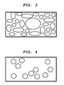
Figure 3 illustrates another shape as seen from surface observation of the depressed portion according to the present invention. -
Figure 4 illustrates another shape as seen from surface observation of the depressed portion according to the present invention. -
Figure 5 illustrates another shape as seen from surface observation of the depressed portion according to the present invention. -
Figure 6 illustrates another shape as seen from surface observation of the depressed portion according to the present invention. -
Figure 7 illustrates another shape as seen from surface observation of the depressed portion according to the present invention. -
Figure 8 is an image observed by laser microscope of the resin film surface formed in Example 1. -
Figure 9 is an image observed by laser microscope of the resin film surface formed in Example 3. -
Figure 10 is an image observed by laser microscope of the resin film surface formed in Example 4. - The present invention will now be described in more detail.
- In the present invention, the term "hydrophilic solvent" refers to a solvent which exhibits a large affinity with water, and the term "hydrophobic solvent" refers to a solvent which exhibits a small affinity with water. In the present invention, the distinction between "hydrophilic solvent" and "hydrophobic solvent" is made according to the following experiment and criteria.
- First, under normal temperature and humidity conditions (23±3°C, 50±10% RH), 50 ml of water is measured into a 50 ml measuring cylinder. Next, 50 ml of solvent is measured into a 100 ml measuring cylinder, and this cylinder is charged with the 50 ml of water measured in the previous procedure. The resulting solution is thoroughly stirred with a glass rod until the whole solution is uniform. A lid is put on so that the solvent and the water will not volatilize. The solution is left for a sufficiently long period until air bubbles disappear and the surface boundary becomes stable. The state of the mixed solution in the 100 ml measuring cylinder is observed, and the volume of the aqueous phase is measured.
- In cases where the volume of the aqueous phase is 0 ml or more to 5 ml or less, the solvent is classified as hydrophilic. In cases where the volume of the aqueous phase is 45 ml or more to 50 ml or less, the solvent is classified as hydrophobic. In cases of a uniform monophase, the volume of the aqueous phase is 0, and the solvent is classified as being hydrophilic. In cases beyond these ranges, the solvent is not classified as either being hydrophilic or hydrophobic.
- In the above-described experiment, if the solvent is toluene, for example, the volume of the aqueous phase is 50 ml, and thus is classified as hydrophobic. If the solvent is dimethyl sulfoxide (DMSO), a monophase is formed, and thus the volume of the aqueous phase is 0 ml. In this case, the solvent is classified as hydrophilic. Further, if the solvent is 1,1-dimethoxymethane (methylal), the volume of the aqueous phase is 69 ml, and thus the solvent is not classified as either hydrophilic or hydrophobic.
- In the present invention, the expression "dipole moment as calculated from geometry optimization based on a semiempirical molecular-orbital calculation", refers to the value of the dipole moment calculated based on the semiempirical molecular orbital calculation program MOPAC using PM3 parameters. In the molecular-orbital method, a wave function used in the Schroedinger's equation is approximated by the Slater type matricial equation or Gauss type matricial equation consisting of a molecular orbital expressed as a linear combination of atomic orbitals, and the molecular orbital constituting the wave function is found by the use of approximation of field, whereby various physical quantities can be calculated as the total energy, the wave function or as expected values of the wave function.
- Semiempirical molecular-orbital calculation is a method which, when determining a molecular orbital from a field approximation, shortens the calculation time through approximation using parameters in which various actual experiment values are employed whose integral calculations took time to calculate. The calculations in the present invention were calculated based on the semiempirical molecular orbital calculation program MOPAC using PM3 parameters as semiempirical parameters.
- Specifically, using an Indigo2 workstation (manufactured by Silicon Graphics) as the computer, the chemical modeling software Cerius2 is used for dipole moment calculation. The molecular structure of the solvent to be calculated is produced using the Sketching function of the Cerius2. The force-field of this molecular structure is calculated using the Dreding 2.21 program to calculate the charge using the Charge function. The structure is then corrected based on a molecular force field calculation using the Minimizer. PM3 parameters, Geometry Optimization and Dipole are specified in the MOPAC93 program, and corrected structure and dipole moment are calculated for the thus-obtained structure.
- The affinity between the solvent and water is related to dipole moment. A hydrophilic solvent tends to have a large dipole moment, while a hydrophobic solvent tends to have a small dipole moment. However, for a highly symmetrical molecular structure, consideration needs to be given to the fact that even a hydrophilic solvent will have a small dipole moment. In the present invention, the tendency is for the hydrophilic solvent A to preferably have a large dipole moment, and the hydrophobic solvent B to preferably have a small dipole moment.
- Representative examples of solvent A and solvent B are respectively shown in the following Tables 1 and 2. However, the solvents A and B according to the present invention are not limited to these examples. The term "dipole moment" in Tables 1 and 2 refers to the dipole moment value as calculated in accordance with the above-described method. Further, as a rule, "boiling point" in Tables 1 and 2 refers to the boiling point at atmospheric pressure. In cases where it does not refer to atmospheric pressure, the pressure is clearly specified.
Table 1 Representative examples of solvent A No. Name Chemical formula Boiling point [°C] Dipole moment [D] 1-1 1,2-Propanediol CH3CHOHCH2OH 187 0.1 1-2 1,3-Butanediol HOCH2CH2CHOHCH3 207 0.1 1-3 1,5-Pentanediol HO(CH2)5OH 242 2.8 1-4 Glycerol 
290 2.3 1-5 1,2,6-Hexanetriol 
178 (5 mmHg) 2.2 1-6 Tetrahydrofuran 
66 1.7 1-7 Diethylene glycol dimethyl ether 
160 1.2 1-8 Propionic acid CH3CH2COOH 141 1.8 1-9 Butyric acid CH3CH2CH2COOH 163 1.8 1-10 γ-Butyrolactone 
204 4.2 1-11 Diethylene glycol diethyl ether H5C2OC2H4-O-C2H4OC2H5 188 1.1 1-12 Monoacetin H3CCOOC3H5(OH)2 182 3.4 1-13 Diacetin (CH3COO)2C3H5OH 172 4.4 1-14 Ethylene carbonate 
238 4.6 1-15 Propylene carbonate 
242 4.8 1-16 Triethyl phosphate PO(OC2H5)3 215 3.6 1-17 β-Picoline 
144 2.1 1-18 γ-Picoline 
145 2.3 1-19 2,4-Lutidine 
157 2.2 1-20 2,6-Lutidine 
144 1.5 1-21 Quinoline 
237 1.8 1-22 Formamide HCONH2 210 3.4 1-23 N,N-Dimethylformamide HCON (CH3)2 153 3.4 1-24 N,N-Diethylformamide HCON(C2H5)2 177 3.4 1-25 N,N-Dimethylacetamid e CH3CON (CH3)2 166 3.2 1-26 N,N,N',N'-Tetramethylurea (CH3)2NCON (CH3)2 177 2.4 1-27 2-Pyrrolidone 
245 3.6 1-28 N-Methyl-2-pyrrolidone 
202 3.3 1-29 Dimethyl sulfoxide (CH3)2SO 189 4.5 1-30 Sulfolane 
287 4.9 1-31 2-Ethoxyethanol C2H5OCH2CH2OH 136 0.03 1-32 Tetrahydrofurfuryl alcohol 
178 1.2 1-33 Diethylene glycol HOC2H4OC2H4OH 245 1.2 1-34 Tetraethylene glycol HO(C2H4O)4H 327 1.7 1-35 1-Ethoxy-2-propanol 
132 2.6 1-36 Dipropylene glycol HOC3H6OC3H6OH 232 3.9 1-37 Dipropylene glycol monomethyl ether H3COC3H6OC3H6OH 190 3.7 1-38 Dipropylene glycol monoethyl ether H5C2OC3H6OC3H6OH 198 3.6 1-39 Tripropylene glycol monoethyl ether H3CO(C3H6O)3H 243 4.7 1-40 Diacetone alcohol 
168 3.3 1-41 3-Chloro-1,2-propanediol CH2ClCH(OH)CH2OH 213 3.1 1-42 N-Butyldiethanolamine 
274 1.1 1-43 Triethanolamine 
360 1.7 1-44 2-Methoxyethyl acetate CH3COOCH2CH2OCH3 144 3.0 1-45 Diethylene glycol monoethyl ether acetate CH3COOCH2CH2 OCH2CH2OC2H5 217 1.8 1-46 Hexamethylphosph oric triamide [(CH3)2N]3P=O 233 2.8 1-47 1,3-Dimethyl-2-imidazolidinone 
225 3.5 1-48 N,N,N',N'-Tetramethylethyl enediamine (CH3)2NCH2CH2 N(CH3)2 121 0.1 1-49 2-methyl-2,4-pentanediol (CH3)2C(OH) -CH2-CH(OH)-CH3 197 2.8 1-50 2-Butoxyethanol H9C4OCH2CH2OH 170 0.4 1-51 Diethylene glycol monomethyl ether H3CO(C2H4O)2H 194 1.5 1-52 Diethylene glycol monoethyl ether H5C2O(C2H4O)2H 202 1.6 1-53 Triethylene glycol HOC2H4OC2H4O C2H4OH 288 0.03 Table 2 Representative examples of solvent B No. Name Chemical formula Boiling point [°C] Dipole moment [D] 2-1 Toluene 
110 0.3 2-2 1,2-Dimethylbenzene 
144 0.5 2-3 1,3- Dimethylbenzene 
139 0.2 2-4 1,4- Dimethylbenzene 
138 0.1 2-5 1,3,5- Trimethylbenzene 
165 0.05 2-6 Monochlorobenzene 
132 0.7 2-7 Pentane C5H12 36 0 2-8 n-Hexane C6H14 69 0 2-9 Cyclohexane 
81 0 2-10 n-Heptane C7H16 98 0 2-11 Dichloromethane CH2Cl2 39 0.9 2-12 Chloroform CHCl3 62 1.0 - Among the solvents listed in Tables 1 and 2, from the perspective of affinity with water, preferable examples of solvent A include dimethyl sulfoxide, sulfolane, ethylene carbonate, propylene carbonate, dimethyl formamide, diethyl formamide, dimethyl acetamide, 2-butoxyethanol, 2-pyrrolidone, N-methyl-2-pyrrolidone, diethylene glycol monomethyl ether, diethylene glycol monoethyl ether, triethylene glycol and dipropylene glycol. Preferable examples of solvent B include aromatic organic solvents. Especially preferable examples include toluene, 1,2-dimethylbenzene, 1,3-dimethylbenzene, 1,4-dimethylbenzene, 1,3,5-trimethylbenzene and monochlorobenzene. These solvents may be used alone, or in combination of two or more thereof. Further, in terms of production stability, solvent A and solvent B preferably have affinity with each other and form a uniform solution; specifically, they are compatible with each other.
- The polymer compound which is soluble in solvent B according to the present invention can be variously selected without restriction depending on the functional properties required in the solid body to be obtained as a product, as long as it is soluble in solvent B. For example, if considering applying to an electronic device, preferable examples would include acrylic resin, methacrylic resin, styrene resin, styrene-acrylonitrile copolymer resin, polyester resin, polycarbonate resin, polyarylate resin, polysulfone resin, polyphenyleneoxide resin, epoxy resin, polyurethane resin, alkyd resin, unsaturated resins, conductive resins, aromatic polyester resins and diallylphthalate resin. Among these examples, in terms of good solubility in solvent B, a polycarbonate resin or aromatic polyester resin is especially preferable. These polymer compounds may be used alone, or in combination of two or more thereof.
- The production method according to the present invention forms a depressed portion from condensation on a surface of a solution during the process of evaporating the solvent in a solution which comprises the above-described solvent A, solvent B, and polymer compound which is soluble in solvent B. Here, "condensation" as used in the present invention refers to water vapor in the air condensing on the solution surface and/or in the solution. Accordingly, the solid body having a depressed portion includes the solid body having a depressed portion only on the surface, the solid body in which pores on the surface is penetrated, and the solid body in which many pores are also present in interior of the solid body.
- Commonly-known methods to promote the condensation of water on the surface of a hydrophobic organic solvent solution of a polymer compound include: promoting condensation by cooling the hydrophobic organic solvent solution of a polymer compound; using a highly volatile organic solvent such as dichloromethane to promote condensation by utilizing the cooling effect from evaporation; promoting condensation by controlling the surrounding environment at a high humidity; promoting condensation by blowing a high-humidity gas; or promoting condensation by controlling the solute in which a special amphiphilic polymer is utilized.
- The production method according to the present invention is characterized in that condensation is promoted by using a hydrophilic solvent A for the solvent of the above-described solution, and controlling the solvent system of the above-described solution. The present invention has the advantages that: the shape and the depth of the depressed portion formed on the surface of the solid body by condensation can be controlled in accordance with the kind and amount of solvent A, or by the combination thereof; costs can be reduced by utilizing a general-purpose solvent; production stability is excellent as a result of the production method being simple; versatility is excellent because no special production equipment is necessary; and the range of applications is broad. However, to achieve a sufficient condensation promotion effect from the solvent A, the solvent A boiling point must be equal to or higher than the solvent B boiling point. If this is not the case, the solvent A will evaporate before the depressed portion can be stably formed by condensation, or condensation water will boil off along with solvent A, whereby the depressed portion might not be able to be formed.
- Further, in the production method according to the present invention, the total mass of the hydrophobic solvent B has to be 50% or more of the total mass of the solvents contained in the above-described solution in order to form the depressed portion from condensation on the surface of the solid body. If this range is not satisfied, it may be difficult to form the depressed portion from condensation.
- Further, in the present invention, in the case of using two or more kinds of solvent A together, the boiling point of the solvent with the highest composition ratio among such solvents becomes the "solvent A boiling point". Similarly, in the case of using two or more kinds of solvent B together, the boiling point of the solvent with the highest composition ratio among such solvents becomes the "solvent B boiling point".
- In the production method according to the present invention, the above-described solution can be treated in a variety of different ways depending on the functional properties required in the solid body to be obtained as a product. For example, for the solid body, if forming a surface layer having a depressed portion, the surface layer can be coated onto the substrate by a well-known method such as dip coating or spin coating, to form the surface layer having a depressed portion. Further, a thin membrane or film can be fabricated by peeling off a film formed on the substrate by these same methods from the substrate. In addition, a thin membrane or film can be fabricated by flowing the above-described solution over a water surface.
- Further, in the production method according to the present invention, various compounds may be added to the solution for the purpose of conferring functionality to the solid body to be obtained as a product, such as a plasticizer, crosslinking agent, metal fine particles, organic fine particles, electrically conductive compound, antimicrobial agent or the like. Moreover, the kind or amount of solvent A and solvent B may be varied or two or more kinds of solvent can be used together in order to control of the solution viscosity, dew point or overall coated surface smoothness, modify the dissolving power of the solvent system of the solution, or control the size and depth of the pores in the product. In addition, various solvents other than solvent A and solvent B may be used. It is also possible to combine the step of modifying the temperature of the solution, the temperature of the substrate over which the solution flows, and the humidity of the surrounding environment, and the step of blowing a high-humidity gas onto the surface of the solution.
- The present invention will now be described in more detail with reference to specific examples. However, the present invention is not intended to be limited to these examples. In the examples, the term "parts" means "parts by mass" and "MW" means "weight average molecular weight (MW)".
- A solution was prepared by mixing together and dissolving 6 parts of dimethyl sulfoxide as solvent A, 54 parts of monochlorobenzene as solvent B and 12 parts of polycarbonate resin ("Iupilon Z200", manufactured by Mitsubishi Gas Chemical Company, Inc.) as the polymer compound. Next, this solution was coated onto a glass plate under normal temperature and humidity conditions (23°C, 50% RH). Then, while evaporating the solvent by leaving the glass plate for 10 minutes under normal temperature and humidity conditions, a depressed portion was formed on the coated film surface. The glass plate was then dried by heating for 1 hour at 150°C to form a polycarbonate resin film on the glass plate. Observation of this resin film with a laser microscope ("VK-9500", manufactured by Keyence Corporation) showed that shapes were formed on the surface which had a plurality of pores regularly formed thereon. The pore diameter was about 14 µm, and the depth was about 10 µm. The observed results of this surface are shown in
Figure 8 . The contact angle with water on the thus-formed resin film was measured at 110°, which is a high contact angle showing that the resin film was water repellent. The friction coefficient was measured to be 0.8. These results are shown in Table 3-1. The contact angle with respect to water and the friction coefficient were measured in accordance with the following methods. - Contact angle was measured by a droplet method using pure water under normal temperature and humidity conditions (23±3°C, 50±10% RH) with a contact angle meter (CA-VP series) and accompanying application software ("FAMAS version 21.0"), both manufactured by Kyowa Interface Science Co., Ltd. Measurement was conducted 0.3 seconds after a pure water drop had adhered to the surface by setting the "Auto Dispenser AD-21", also manufactured by Kyowa Interface Science Co., Ltd., to Level 50 and modifying the amount of pure water.
- Using a "Tribostation Type 32" manufactured by Shinto Scientific Co., Ltd., a urethane rubber blade (rubber hardness of 77 degrees) manufactured by Bando Chemical Industries Limited was mounted onto a blade holder. Then, under normal temperature and humidity conditions (23±3°C, 50±10% RH), friction coefficient was measured by adjusting to conditions of a 20 g load, 22.5° contact angle and 10 mm abutting width.
- A solution was prepared, without using any solvent A, by mixing together and dissolving 60 parts of monochlorobenzene and 12 parts of polycarbonate resin ("Iupilon Z200", manufactured by Mitsubishi Gas Chemical Company, Inc.). Next, this solution was coated onto a glass plate under normal temperature and humidity conditions (23°C, 50% RH). Then, the solvent was made to evaporate by leaving the glass plate for 10 minutes under normal temperature and humidity conditions. The glass plate was then dried by heating for 1 hour at 150°C to form a polycarbonate resin film on the glass plate. Observation of this resin film in the same manner as in Example 1 with a laser microscope ("VK-9500", manufactured by Keyence Corporation) showed that depressed portions were not formed. The contact angle with water of the thus-formed resin film was measured at 75°. The friction coefficient was measured to be 1.2. These results are shown in Table 3-3.
- A solution was prepared by mixing together and dissolving 1.8 parts of dimethyl sulfoxide as solvent A, 58.2 parts of monochlorobenzene as solvent B and 12 parts of polycarbonate resin ("Iupilon Z200", manufactured by Mitsubishi Gas Chemical Company, Inc.) as the polymer compound. In the same manner as in Example 1, the solution was coated onto a glass plate and left to stand, then dried by heating to form a polycarbonate resin film. In the same manner as in Example 1, the surface state was observed, and the contact angle with water and the friction coefficient were measured. The results of the contact angle and friction coefficient measurements are shown in Table 3-1. Further, a plurality of pores were regularly formed on the surface of the resin film. The pore diameter was about 6 µm, and the depth was about 4 µm.
- A solution was prepared by mixing together and dissolving 9 parts of N,N-dimethylformamide as solvent A, 51 parts of monochlorobenzene as solvent B and 12 parts of polycarbonate resin ("Iupilon Z200", manufactured by Mitsubishi Gas Chemical Company, Inc.) as the polymer compound. Next, this solution was coated onto a glass plate under normal temperature and humidity conditions (23°C, 50% RH). Then, while evaporating the solvent by standing the glass plate for 24 hours under normal temperature and humidity conditions, a depressed portion was formed on the coated film surface, and a polycarbonate resin film was formed on the glass plate. In the same manner as in Example 1, the surface state of this resin was observed, and the contact angle with water and the friction coefficient were measured. The observed results of the surface are shown in
Figure 9 , and the results of the contact angle and friction coefficient measurements are shown in Table 3-1. - A solution was prepared by mixing together and dissolving 9 parts of N,N-dimethylacetamide as solvent A, 51 parts of monochlorobenzene as solvent B and 12 parts of polycarbonate resin ("Iupilon Z200", manufactured by Mitsubishi Gas Chemical Company, Inc.) as the polymer compound. Next, this solution was coated onto a glass plate under normal temperature and humidity conditions (23°C, 50% RH). Then, while evaporating the solvent by standing the glass plate for 24 hours under normal temperature and humidity conditions, a depressed portion was formed on the coated film surface, and a polycarbonate resin film was formed on the glass plate. In the same manner as in Example 1, the surface state of this resin was observed, and the contact angle with water and the friction coefficient were measured. The observed results of the surface are shown in
Figure 10 , and the results of the contact angle and friction coefficient measurements are shown in Table 3-1. - A solution was prepared by mixing together and dissolving 6 parts of ethylene carbonate as solvent A, 48 parts of monochlorobenzene as solvent B, 6 parts of dimethoxymethane as another solvent and 12 parts of polycarbonate resin ("Iupilon Z200", manufactured by Mitsubishi Gas Chemical Company, Inc.) as the polymer compound. In the same manner as in Example 1, the solution was coated onto a glass plate and left to stand, then dried by heating to form a polycarbonate resin film. In the same manner as in Example 1, the surface state was observed, and the contact angle with water and the friction coefficient were measured. A plurality of pores were formed on the surface of the resin film. The results of the contact angle and friction coefficient measurements are shown in Table 3-1.
- A solution was prepared, without using any solvent A, by mixing together and dissolving 54 parts of monochlorobenzene, 6 parts of dimethoxymethane and 12 parts of polycarbonate resin ("Iupilon Z200", manufactured by Mitsubishi Gas Chemical Company, Inc.). Next, this solution was coated onto a glass plate under normal temperature and humidity conditions (23°C, 50% RH). Then, the solvent was made to evaporate by leaving the glass plate for 10 minutes under normal temperature and humidity conditions. The glass plate was then dried by heating for 1 hour at 150°C to form a polycarbonate resin film on the glass plate. Observation of this resin film in the same manner as in Example 1 with a laser microscope ("VK-9500", manufactured by Keyence Corporation) showed that depressed portions were not formed. The contact angle with water of the thus-formed resin film was measured at 75°. The friction coefficient was measured to be 1.2. These results are shown in Table 3-3.
- A solution was prepared by mixing together and dissolving 9 parts of tetrahydrofurfuryl alcohol as solvent A, 51 parts of monochlorobenzene as solvent B, and 12 parts of polycarbonate resin ("Iupilon Z200", manufactured by Mitsubishi Gas Chemical Company, Inc.) as the polymer compound. In the same manner as in Example 1, the solution was coated onto a glass plate and left to stand, then dried by heating to form a polycarbonate resin film. In the same manner as in Example 1, the surface state was observed, and the contact angle with water and the friction coefficient were measured. A plurality of pores were formed on the surface of the resin film. The results of the contact angle and friction coefficient measurements are shown in Table 3-1.
- A solution was prepared by mixing together and dissolving 6 parts of 2-pyrrolidone as solvent A, 54 parts of monochlorobenzene as solvent B and 12 parts of polycarbonate resin ("Iupilon Z200", manufactured by Mitsubishi Gas Chemical Company, Inc.) as the polymer compound. In the same manner as in Example 1, the solution was coated onto a glass plate and left to stand, then dried by heating to form a polycarbonate resin film. In the same manner as in Example 1, the surface state was observed, and the contact angle with water and the friction coefficient were measured. A plurality of pores were formed on the surface of the resin film. The results of the contact angle and friction coefficient measurements are shown in Table 3-1.
- A solution was prepared by mixing together and dissolving 6 parts of N-methyl-2-pyrrolidone as solvent A, 54 parts of monochlorobenzene as solvent B and 12 parts of polycarbonate resin ("Iupilon Z200", manufactured by Mitsubishi Gas Chemical Company, Inc.) as the polymer compound. In the same manner as in Example 1, the solution was coated onto a glass plate and left to stand, then dried by heating to form a polycarbonate resin film. In the same manner as in Example 1, the surface state was observed, and the contact angle with water and the friction coefficient were measured. A plurality of pores were formed on the surface of the resin film. The results of the contact angle and friction coefficient measurements are shown in Table 3-1.
- A solution was prepared by mixing together and dissolving 3 parts of 2-methyl-2,4-pentanediol as solvent A, 57 parts of monochlorobenzene as solvent B and 12 parts of polycarbonate resin ("Iupilon Z200", manufactured by Mitsubishi Gas Chemical Company, Inc.) as the polymer compound. In the same manner as in Example 1, the solution was coated onto a glass plate and left to stand, then dried by heating to form a polycarbonate resin film. In the same manner as in Example 1, the surface state was observed, and the contact angle with water and the friction coefficient were measured. A plurality of pores were formed on the surface of the resin film. The results of the contact angle and friction coefficient measurements are shown in Table 3-1.
- A solution was prepared by mixing together and dissolving 6 parts of triethylene glycol as solvent A, 54 parts of monochlorobenzene as solvent B and 12 parts of polycarbonate resin ("Iupilon Z200", manufactured by Mitsubishi Gas Chemical Company, Inc.) as the polymer compound. In the same manner as in Example 1, the solution was coated onto a glass plate and left to stand, then dried by heating to form a polycarbonate resin film. In the same manner as in Example 1, the surface state was observed, and the contact angle with water and the friction coefficient were measured. A plurality of pores were formed on the surface of the resin film. The results of the contact angle and friction coefficient measurements are shown in Table 3-1.
- A solution was prepared by mixing together and dissolving 4 parts of dimethyl sulfoxide as solvent A, 22 parts of toluene as solvent B, 14 parts of dimethoxymethane as another solvent and 4 parts of polyarylate resin having the following structure as the polymer compound. Next, this solution was dip-coated onto a glass plate under normal temperature and humidity conditions (23°C, 50% RH). Then, while evaporating the solvent by leaving the glass plate for 10 minutes under normal temperature and humidity conditions, an depressed portion was formed on the coated film surface. The glass plate was then dried by heating for 1 hour at 150°C to form a polyarylate resin film on the glass plate. The surface state of this resin film was observed in the same manner as in Example 1, and the contact angle with water and the friction coefficient were measured. A plurality of pores were regularly formed on the surface of the resin film. The results of the contact angle and friction coefficient measurements are shown in Table 3-2.

- Note: The aromatic dicarboxylic acid moiety in the above structural formula represents a fifty-fifty mixture of terephthalic acid and isophthalic acid.
- A solution was prepared, without using any solvent A, by mixing together and dissolving 26 parts of toluene, 14 parts of dimethoxymethane and 4 parts of polyarylate resin having the following structure. Next, this solution was dip-coated onto a glass plate under normal temperature and humidity conditions (23°C, 50% RH). Then, the solvent was made to evaporate by leaving the glass plate for 10 minutes under normal temperature and humidity conditions. The glass plate was then dried by heating for 1 hour at 150°C to form a polyarylate resin film on the glass plate. Observation of this resin film in the same manner as in Example 1 with a laser microscope ("VK-9500", manufactured by Keyence Corporation) showed that depressed portions were not formed. The contact angle with water of the thus-formed resin film was measured at 77°. The friction coefficient was measured to be 1.5. These results are shown in Table 3-3.

- Note: The aromatic dicarboxylic acid moiety in the above structural formula represents a fifty-fifty mixture of terephthalic acid and isophthalic acid.
- A solution was prepared by mixing together and dissolving 6 parts of 2-butoxyethanol as solvent A, 54 parts of monochlorobenzene as solvent B and 6 parts of polyarylate resin having the following structure as the polymer compound. In the same manner as in Example 11, the solution was dip-coated onto a glass plate and left to stand, then dried by heating to form a polyarylate resin film. In the same manner as in Example 1, the surface state was observed, and the contact angle with water and the friction coefficient were measured. A plurality of pores were formed on the surface of the resin film. The results of the contact angle and friction coefficient measurements are shown in Table 3-2.

- Note: The aromatic dicarboxylic acid moiety in the above structural formula represents a fifty-fifty mixture of terephthalic acid and isophthalic acid.
- A solution was prepared, without using any solvent A, by mixing together and dissolving 60 parts of monochlorobenzene and 6 parts of polyarylate resin having the following structure. Next, this solution was dip-coated onto a glass plate under normal temperature and humidity conditions (23°C, 50% RH). Then, the solvent was made to evaporate by leaving the glass plate for 10 minutes under normal temperature and humidity conditions. The glass plate was then dried by heating for 1 hour at 150°C to form a polyarylate resin film on the glass plate. Observation of this resin film in the same manner as in Example 1 with a laser microscope ("VK-9500", manufactured by Keyence Corporation) showed that depressed portions were not formed. The contact angle with water of the thus-formed resin film was measured at 76°. The friction coefficient was measured to be 1.5. These results are shown in Table 3-3.

- Note: The aromatic dicarboxylic acid moiety in the above structural formula represents a fifty-fifty mixture of terephthalic acid and isophthalic acid.
- A solution was prepared by mixing together and dissolving 6 parts of diethylene glycol monomethyl ether as solvent A, 54 parts of monochlorobenzene as solvent B and 6 parts of polyarylate resin having the following structure as the polymer compound. In the same manner as in Example 11, the solution was dip-coated onto a glass plate and left to stand, then dried by heating to form a polyarylate resin film. In the same manner as in Example 1, the surface state was observed, and the contact angle with water and the friction coefficient were measured. A plurality of pores were formed on the surface of the resin film. The results of the contact angle and friction coefficient measurements are shown in Table 3-2.

- Note: The aromatic dicarboxylic acid moiety in the above structural formula represents a fifty-fifty mixture of terephthalic acid and isophthalic acid.
- A solution was prepared by mixing together and dissolving 6 parts of diethylene glycol monoethyl ether as solvent A, 54 parts of monochlorobenzene as solvent B and 6 parts of polyarylate resin having the following structure as the polymer compound. In the same manner as in Example 11, the solution was dip-coated onto a glass plate and left to stand, then dried by heating to form a polyarylate resin film. In the same manner as in Example 1, the surface state was observed, and the contact angle with water and the friction coefficient were measured. A plurality of pores were formed on the surface of the resin film. The results of the contact angle and friction coefficient measurements are shown in Table 3-2.

- Note: The aromatic dicarboxylic acid moiety in the above structural formula represents a fifty-fifty mixture of terephthalic acid and isophthalic acid.
- A solution was prepared by mixing together and dissolving 6 parts of dipropylene glycol as solvent A, 54 parts of monochlorobenzene as solvent B and 6 parts of polyarylate resin having the following structure as the polymer compound. In the same manner as in Example 11, the solution was dip-coated onto a glass plate and left to stand, then dried by heating to form a polyarylate resin film. In the same manner as in Example 1, the surface state was observed, and the contact angle with water and the friction coefficient were measured. A plurality of pores were formed on the surface of the resin film. The results of the contact angle and friction coefficient measurements are shown in Table 3-2.

- Note: The aromatic dicarboxylic acid moiety in the above structural formula represents a fifty-fifty mixture of terephthalic acid and isophthalic acid.
- A solution was prepared by mixing together and dissolving 6 parts of polyethylene glycol 200 (average molecular weight of 190 to 200) as solvent A, 54 parts of monochlorobenzene as solvent B and 6 parts of polyarylate resin having the following structure as the polymer compound. In the same manner as in Example 11, the solution was dip-coated onto a glass plate and left to stand, then dried by heating to form a polyarylate resin film. In the same manner as in Example 1, the surface state was observed, and the contact angle with water and the friction coefficient were measured. A plurality of pores were formed on the surface of the resin film. The results of the contact angle and friction coefficient measurements are shown in Table 3-2.

- Note: The aromatic dicarboxylic acid moiety in the above structural formula represents a fifty-fifty mixture of terephthalic acid and isophthalic acid.
- A solution was prepared by mixing together and dissolving 8 parts of diethylene glycol diethyl ether as solvent A, 32 parts of cyclohexane as solvent B and 8 parts of cyclic olefin copolymer ("Topas 5013", manufactured by Ticona Limited) having the following structure as the polymer compound. Next, this solution was spin-coated onto a glass plate under normal temperature and humidity conditions (23°C, 50% RH). Then, while evaporating the solvent by leaving the glass plate for 10 minutes under normal temperature and humidity conditions, a depressed portion was formed on the coated film surface. The glass plate was then dried by heating for 1 hour at 150°C to form a resin film on the glass plate. The surface state of this resin film was observed in the same manner as in Example 1, and the contact angle with water and the friction coefficient were measured. A plurality of pores were regularly formed on the surface of the resin film. The results of the contact angle and friction coefficient measurements are shown in Table 3-2.

- A solution was prepared, without using any solvent A, by mixing together and dissolving 40 parts of cyclohexane and 8 parts of cyclic olefin copolymer ("Topas 5013", manufactured by Ticona Limited) having the following structure as the polymer compound. Next, this solution was spin-coated onto a glass plate under normal temperature and humidity conditions (23°C, 50% RH). Then, the solvent was made to evaporate by leaving the glass plate for 10 minutes under normal temperature and humidity conditions. The glass plate was then dried by heating for 1 hour at 150°C to form a resin film on the glass plate. Observation of this resin film in the same manner as in Example 1 with a laser microscope ("VK-9500", manufactured by Keyence Corporation) showed that depressed portions were not formed. The contact angle with water of the thus-formed resin film was measured at 80°. The friction coefficient was measured to be 1.0. These results are shown in Table 3-3.

- A solution was prepared by mixing together and dissolving 4 parts of tetrahydrofurfuryl alcohol as solvent A, 36 parts of cyclohexane as solvent B and 8 parts of cyclic olefin copolymer ("Topas 5013", manufactured by Ticona) having the following structure as the polymer compound. In the same manner as in Example 17, the solution was spin-coated onto a glass plate and left to stand, then dried by heating to form a resin film. In the same manner as in Example 1, the surface state was observed, and the contact angle with water and the friction coefficient were measured. A plurality of pores were formed on the surface of the resin film. The results of the contact angle and friction coefficient measurements are shown in Table 3-2.

- A solution was prepared by mixing together and dissolving 4 parts of N,N,N',N'-tetramethylurea as solvent A, 36 parts of cyclohexane as solvent B and 8 parts of cyclic olefin copolymer ("Topas 5013", manufactured by Ticona Limited) having the following structure as the polymer compound. In the same manner as in Example 17, the solution was spin-coated onto a glass plate and left to stand, then dried by heating to form a resin film. In the same manner as in Example 1, the surface state was observed, and the contact angle with water and the friction coefficient were measured. A plurality of pores were formed on the surface of the resin film. The results of the contact angle and friction coefficient measurements are shown in Table 3-2.

- A solution was prepared by mixing together and dissolving 4 parts of N,N,N',N'-tetramethylethylenediamine as solvent A, 36 parts of cyclohexane as solvent B and 8 parts of cyclic olefin copolymer ("Topas 5013", manufactured by Ticona Limited) having the following structure as the polymer compound. In the same manner as in Example 17, the solution was spin-coated onto a glass plate and left to stand, then dried by heating to form a resin film. In the same manner as in Example 1, the surface state was observed, and the contact angle with water and the friction coefficient were measured. A plurality of pores were formed on the surface of the resin film. The results of the contact angle and friction coefficient measurements are shown in Table 3-2.
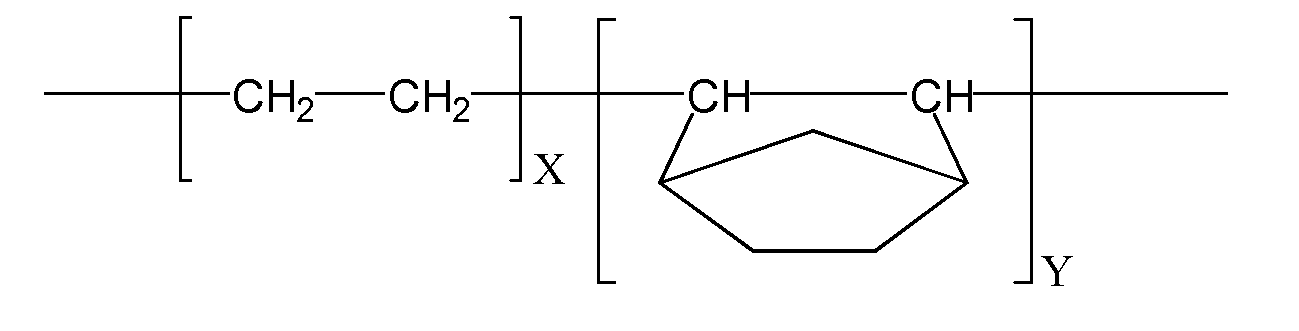
Table 3-1 No. Solvent A Solvent B Other solvent Polymer compound Contact angle Friction coefficient Dipole moment Boiling point Parts by mass Dipole moment Boiling point Parts by mass Dipole moment Boiling point Parts by mass Parts by mass Ex. 1 Dimethylsulfoxide Monochlorobenzene - - Polycarbonate resin 110 0.8 4.5 [D] 189 [°C] 6 0.953[D ] 131.7 [°C ] 54 12 Ex. 2 Dimethylsulfoxide Monochlorobenzene - - Polycarbonate resin 112 0.8 4.5 [D] 189 [°C] 1.8 0.953[D ] 131.7 [°C ] 58.2 12 Ex. 3 N,N-dimethylformamide Monochlorobenzene - - Polycarbonate resin 123 0.7 3.4 [D] 153[°C] 9 0.953[D ] 131.7 [°C ] 51 12 Ex. 4 N,N-dimethylacetamide Monochlorobenzene - - Polycarbonate resin 128 0.7 3.2 [D] 166 [°C] 9 0.953[D ] 131.7 [°C ] 51 12 Ex. 5 Ethylenecarbonate Monochlorobenzene Dimethoxymethane Polycarbonate resin 105 0.9 4.6[D] 238 [°C] 6 0.953[D ] 131.7 [°C ] 48 2.4[D] 42.3[° C] 6 12 Ex. 6 Tetrahydrofurfuryl alcohol Monochlorobenzene - - Polycarbonate resin 92 1.0 1.2 [D] 178 [°C] 9 0.953[D ] 131.7 [°C ] 51 12 Ex. 7 2-pyrrolidone Monochlorobenzene - - Polycarbonate resin 120 0.7 3.6[D] 245 [°C] 6 0.953[D ] 131.7 [°C ] 54 12 Ex. 8 N-methyl-2-pyrrolidone Monochlorobenzene - - Polycarbonate resin 100 0.9 3.3 [D] 202 [°C] 6 0.953[D ] 131.7 [°C ] 54 12 Ex. 9 2-methyl-2,4-pentanediol Monochlorobenzene - - Polycarbonate resin 96 0.9 2.8 [D] 197 [°C] 3 0.953[D ] 131.7 [°C ] 57 12 Ex. 10 Triethyleneglycol Monochloroben zene - - Polycarbonate resin 110 0.8 0.03 [D] 288 [°C] 6 0.953[D ] 131.7 [°C ] 54 12 Table 3-2 No. Solvent A Solvent B Other solvent Polymer compound Contact angle Friction coefficient Dipole moment Boiling point Parts by mass Dipole moment Boiling point Parts by mass Dipole moment Boiling point Parts by mass Parts by mass Ex. 11 Dimethylsulfoxide Toluene Dimethoxymethane Polyarylate resin 104 1.2 4.5 [D] 189 [°C] 4 0.261[D ] 110.6 [° C] 22 2.4 [D] 42.3 [° C] 14 4 Ex. 12 2-butoxyethanol Monochlorobenzene - - Polyarylate resin 110 1.0 0.4 [D] 170 [°C] 6 0.953[D ] 131.7 [° C] 54 6 Ex. 13 Diethylene glycol monomethylether Monochlorobenzene - - Polyarylate resin 110 1.0 1.5 [D] 194[°C] 6 0.953[D ] 131.7 [° C] 54 6 Ex. 14 Diethylene glycol monoethylether Monochlorobenzene - - Polyarylate resin 108 1.0 1.6[D] 202 [°C] 6 0.953[D ] 131.7 [° C] 54 6 Ex. 15 Dipropyleneglycol Monochlorobe nzene - - Polyarylate resin 103 1.2 3.9[D] 232 [°C] 6 0.953[D ] 131.7[° C] 54 6 Ex. 16 Polyethyleneglycol 200 Monochlorobe nzene - - Polyarylate resin 112 0.8 250 [°C] 6 0.953[D ] 131.7 [° C] 54 6 Ex. 17 Diethylene glycol diethylether Cyclohexane - - Cyclic olefin copolymer 115 0.8 1.1[D] 188 [°C] 8 0 [D] 81 [°C] 32 8 Ex. 18 Tetrahydrofurfuryl alcohol Cyclohexane - - Cyclic olefin copolymer 120 0.8 1.2 [D] 178 [°C] 4 0 [D] 81 [°C] 36 8 Ex. 19 N,N,N',N'-tetramethylurea Cyclohexane - - Cyclic olefin copolymer 125 0.7 2.4 [D] 177[°C] 4 0 [D] 81 [°C] 36 8 Ex. 20 N,N,N',N'-tetramethyle thylenediamine Cyclohexane - - Cyclic olefin copolymer 90 0.9 0.1 [D] 121 [°C] 4 0 [D] 81 [°C] 36 8 Table 3-3 No. Solvent A Solvent B Other solvent Polymer compound Contact angle Friction coefficient Dipole moment Boiling point Parts by mass Dipole moment Boiling point Parts by mass Dipole moment Boiling point Parts by mass Parts by mass Com. ex. 1 - - Monochlorobenzene - - Polycarbonate resin 75 1.2 0.953[D [°C 131.7 ] 60 12 Com. ex. 2 - - Monochlorobenzene Dimethoxymethane Polycarbonate resin 75 1.2 0.953[D 131.7[°C ] 54 2.4[D] 42.3[° C] 6 12 Com. ex. 3 - - Toluene Dimethoxymethane Polyarylate resin 77 1.5 0.261[D 110.6[°C ] 26 2.4 [D] 42.3 [° C] 14 4 Com. ex. 4 - - Monochlorobenzene - - Polyarylate resin 76 1.5 0.953[D 131.7[°C ] 60 6 Com. ex. 5 - - Cyclohexane - - Cyclic olefin copolymer 80 1.0 0 [D] 81 [°C] 40 8 - As is clear from the results of Examples 1 to 16 and Comparative Examples 1 to 4, and from Examples 17 to 20 and Comparative Example 5, depending on the kind of solvent A, it is possible to form various porous surface shapes having a high contact angle and a low friction coefficient. Further, as is clear from the results of Examples 1 and 2 and Comparative Example 1, depending on the amount of solvent A, it is possible to control surface pore diameter and depth.
- While the present invention has been described with reference to exemplary embodiments, it is to be understood that the invention is not limited to the disclosed exemplary embodiments. The scope of the following claims is to be accorded the broadest interpretation so as to encompass all such modifications and equivalent structures and functions.
- The present application claims priority from Japanese Patent Application No.
2007-016222 which was filed on January 26, 2007
Claims (10)
- A method of producing a solid body having a depressed portion on a surface, characterized by:using a solution at least comprising a solvent A, a solvent B and a polymer compound soluble in solvent B, solvent A being a hydrophilic solvent and solvent B being a hydrophobic solvent, the boiling point of solvent A being equal to or higher than the boiling point of solvent B, and the total mass of solvent B being 50% or more of the total mass of the solvents contained in the solution; andsolidifying the solution while forming a depressed portion from condensation on the surface of the solution during a process wherein either one or both of the solvent A and solvent B contained in the solution are evaporating.
- The method of producing a solid body according to claim 1, characterized in that solvent A and solvent B are compatible.
- The method of producing a solid body according to claim 1 or 2 characterized in that a dipole moment as calculated from geometry optimization based on a semiempirical molecular-orbital calculation of solvent A is 2.0 or more.
- The method of producing a solid body according to claim 1 or 2, characterized in that a dipole moment as calculated from geometry optimization based on a semiempirical molecular-orbital calculation of solvent A is 3.0 or more.
- The method of producing a solid body according to claim 1 or 2, characterized in that a dipole moment as calculated from geometry optimization based on a semiempirical molecular-orbital calculation of solvent A is 4.0 or more.
- The method of producing a solid body according to any one of claims 1 to 5, characterized in that a dipole moment as calculated from geometry optimization based on a semiempirical molecular-orbital calculation of solvent B is 1.0 or less.
- The method of producing a solid body according to any one of claims 1 to 6, characterized in that solvent B is an aromatic organic solvent.
- The method of producing a solid body according to any one of claims 1 to 7, characterized in that the polymer compound soluble in solvent B is polycarbonate resin and/or aromatic polyester resin.
- The method of producing a solid body according to any one of claims 1 to 8, characterized in that the aromatic organic solvent is at least one or more solvents selected from the group consisting of toluene, 1,2-dimethylbenzene, 1,3-dimethylbenzene, 1,4-dimethylbenzene, 1,3,5-trimethylbenzene and monochlorobenzene.
- The method of producing a solid body according to any one of claims 1 to 9, characterized in that solvent A is at least one or more solvents selected from the group consisting of dimethyl sulfoxide, sulfolane, ethylene carbonate, propylene carbonate, dimethyl formamide, diethyl formamide, dimethyl acetamide, 2-butoxyethanol, 2-pyrrolidone, N-methyl-2-pyrrolidone, diethylene glycol monomethyl ether, diethylene glycol monoethyl ether, triethylene glycol and dipropylene glycol.
The present application claims priority from Japanese Patent Application No. 2007-016222 which was filed on January 26, 2007, which is herein incorporated by reference in its entirety.
Applications Claiming Priority (2)
| Application Number | Priority Date | Filing Date | Title |
|---|---|---|---|
| JP2007016222A JP4018741B1 (en) | 2007-01-26 | 2007-01-26 | Method for producing a solid having a concave shape on the surface |
| PCT/JP2007/051847 WO2008090634A1 (en) | 2007-01-26 | 2007-01-30 | Process for production of solid products having depressions on the surface |
Publications (3)
| Publication Number | Publication Date |
|---|---|
| EP2127842A1 true EP2127842A1 (en) | 2009-12-02 |
| EP2127842A4 EP2127842A4 (en) | 2010-03-03 |
| EP2127842B1 EP2127842B1 (en) | 2014-01-29 |
Family
ID=38857807
Family Applications (1)
| Application Number | Title | Priority Date | Filing Date |
|---|---|---|---|
| EP07713808.9A Not-in-force EP2127842B1 (en) | 2007-01-26 | 2007-01-30 | Process for production of solid products having depressions on the surface |
Country Status (6)
| Country | Link |
|---|---|
| US (1) | US7931848B2 (en) |
| EP (1) | EP2127842B1 (en) |
| JP (1) | JP4018741B1 (en) |
| KR (1) | KR101122799B1 (en) |
| CN (1) | CN101583474B (en) |
| WO (1) | WO2008090634A1 (en) |
Cited By (1)
| Publication number | Priority date | Publication date | Assignee | Title |
|---|---|---|---|---|
| EP2565222A1 (en) * | 2011-08-31 | 2013-03-06 | Constantia Hueck Folien GmbH & Co. KG | Sealing wax |
Families Citing this family (26)
| Publication number | Priority date | Publication date | Assignee | Title |
|---|---|---|---|---|
| JPWO2009041352A1 (en) * | 2007-09-25 | 2011-01-27 | 富士フイルム株式会社 | Method for producing porous film, porous film and composite material |
| WO2009041376A1 (en) * | 2007-09-27 | 2009-04-02 | Fujifilm Corporation | Process for producing porous structure |
| JP5534750B2 (en) * | 2008-09-19 | 2014-07-02 | キヤノン株式会社 | Method for producing solid material having concave portion on surface and method for producing electrophotographic photosensitive member |
| JP2010185057A (en) * | 2009-02-13 | 2010-08-26 | Polyplastics Co | Method for producing cyclic olefin-based resin foam |
| JP5537857B2 (en) | 2009-07-30 | 2014-07-02 | 富士フイルム株式会社 | Method for producing porous film |
| JP4663819B1 (en) | 2009-08-31 | 2011-04-06 | キヤノン株式会社 | Electrophotographic equipment |
| JP5629588B2 (en) * | 2010-01-15 | 2014-11-19 | キヤノン株式会社 | Electrophotographic photosensitive member, process cartridge, and electrophotographic apparatus |
| CN103109236B (en) | 2010-09-14 | 2015-03-25 | 佳能株式会社 | Electrophotographic photosensitive member, process cartridge, electrophotographic apparatus, and method of manufacturing electrophotographic photosensitive member |
| JP4948670B2 (en) | 2010-10-14 | 2012-06-06 | キヤノン株式会社 | Electrophotographic photosensitive member, process cartridge, electrophotographic apparatus, and method of manufacturing electrophotographic photosensitive member |
| JP4959022B2 (en) | 2010-10-29 | 2012-06-20 | キヤノン株式会社 | Electrophotographic photosensitive member, process cartridge, and electrophotographic apparatus |
| JP5036901B1 (en) | 2010-10-29 | 2012-09-26 | キヤノン株式会社 | Electrophotographic photosensitive member, process cartridge, electrophotographic apparatus, and method of manufacturing electrophotographic photosensitive member |
| JP4975185B1 (en) | 2010-11-26 | 2012-07-11 | キヤノン株式会社 | Method for forming uneven shape on surface of surface layer of cylindrical electrophotographic photoreceptor, and method for producing cylindrical electrophotographic photoreceptor having uneven surface formed on surface of surface layer |
| JP4959024B1 (en) | 2010-12-02 | 2012-06-20 | キヤノン株式会社 | Electrophotographic photosensitive member, process cartridge, electrophotographic apparatus, and method of manufacturing electrophotographic photosensitive member |
| JP5588915B2 (en) * | 2011-04-14 | 2014-09-10 | 株式会社ノリタケカンパニーリミテド | Cycloolefin polymer structure and method for producing the same |
| US20140099445A1 (en) * | 2012-10-09 | 2014-04-10 | University Of Massachusetts | Method for producing a film having a nano-structure on the surface of the film |
| KR20150064438A (en) * | 2013-12-03 | 2015-06-11 | 삼성에스디아이 주식회사 | Separator containing coating layer, method for manufacturing the separator and battery using the separator |
| JP6588731B2 (en) | 2015-05-07 | 2019-10-09 | キヤノン株式会社 | Electrophotographic photosensitive member, process cartridge, and electrophotographic apparatus |
| JP6639256B2 (en) | 2016-02-10 | 2020-02-05 | キヤノン株式会社 | Electrophotographic apparatus and process cartridge |
| WO2018082024A1 (en) * | 2016-11-04 | 2018-05-11 | The University Of Hong Kong | Omniphobic porous membrane and methods for preparing the same |
| JP7240124B2 (en) * | 2017-10-16 | 2023-03-15 | キヤノン株式会社 | Electrophotographic photoreceptor, process cartridge and electrophotographic apparatus |
| JP7046571B2 (en) | 2017-11-24 | 2022-04-04 | キヤノン株式会社 | Process cartridges and electrophotographic equipment |
| JP7187270B2 (en) | 2017-11-24 | 2022-12-12 | キヤノン株式会社 | Process cartridge and electrophotographic device |
| JP7057104B2 (en) | 2017-11-24 | 2022-04-19 | キヤノン株式会社 | Process cartridge and electrophotographic image forming apparatus |
| US11573499B2 (en) | 2019-07-25 | 2023-02-07 | Canon Kabushiki Kaisha | Process cartridge and electrophotographic apparatus |
| US11320754B2 (en) | 2019-07-25 | 2022-05-03 | Canon Kabushiki Kaisha | Process cartridge and electrophotographic apparatus |
| US12466962B1 (en) * | 2024-10-30 | 2025-11-11 | Valeo Vision | Illuminated body panels including optics having coating with bubbles and method |
Family Cites Families (16)
| Publication number | Priority date | Publication date | Assignee | Title |
|---|---|---|---|---|
| US5238636A (en) * | 1988-03-07 | 1993-08-24 | Rikagaku Kenkyusho | Processes for producing porous polymer films and composite films |
| JPH01268733A (en) * | 1988-04-20 | 1989-10-26 | Brother Ind Ltd | Production of porous membrane |
| JPH08311231A (en) * | 1995-05-17 | 1996-11-26 | Toyota Central Res & Dev Lab Inc | Honeycomb-like porous body and method for manufacturing the same |
| JP2001081229A (en) * | 1999-09-16 | 2001-03-27 | Toyo Cloth Co Ltd | Biodegradable porous membrane and its preparation |
| JP4431233B2 (en) * | 1999-11-30 | 2010-03-10 | テルモ株式会社 | Honeycomb structure and method for preparing the same, and film and cell culture substrate using the structure |
| MXPA03002502A (en) * | 2000-09-24 | 2004-05-05 | 3M Innovative Properties Co | Extrusion method and apparatus. |
| JP2002335949A (en) * | 2001-05-22 | 2002-11-26 | Inst Of Physical & Chemical Res | Three-dimensional tissue culture method of cells using honeycomb structure film |
| JP4731044B2 (en) * | 2001-05-22 | 2011-07-20 | 独立行政法人理化学研究所 | Stretched film and cell culture substrate using the same |
| JP4904025B2 (en) * | 2004-08-06 | 2012-03-28 | 富士フイルム株式会社 | Film production method |
| US8497343B2 (en) * | 2005-04-06 | 2013-07-30 | Sabic Innovative Plastics Ip B.V. | Polyarylate compositions and articles therefrom |
| WO2006126735A1 (en) * | 2005-05-27 | 2006-11-30 | Fujifilm Corporation | Method for producing self-assembled construction |
| JP2007016179A (en) * | 2005-07-11 | 2007-01-25 | Tokai Rubber Ind Ltd | Porous membrane and anisotropic conductive film using the same |
| JP4101278B2 (en) * | 2006-01-31 | 2008-06-18 | キヤノン株式会社 | Electrophotographic photosensitive member, process cartridge, and electrophotographic apparatus |
| JP4183267B2 (en) * | 2006-01-31 | 2008-11-19 | キヤノン株式会社 | Electrophotographic photosensitive member, process cartridge, and electrophotographic apparatus |
| JP4041921B1 (en) * | 2007-01-26 | 2008-02-06 | キヤノン株式会社 | Electrophotographic photoreceptor manufacturing method |
| JP4235673B2 (en) * | 2007-07-17 | 2009-03-11 | キヤノン株式会社 | Method for producing electrophotographic photosensitive member |
-
2007
- 2007-01-26 JP JP2007016222A patent/JP4018741B1/en not_active Expired - Fee Related
- 2007-01-30 EP EP07713808.9A patent/EP2127842B1/en not_active Not-in-force
- 2007-01-30 KR KR1020097017344A patent/KR101122799B1/en not_active Expired - Fee Related
- 2007-01-30 CN CN2007800499111A patent/CN101583474B/en not_active Expired - Fee Related
- 2007-01-30 WO PCT/JP2007/051847 patent/WO2008090634A1/en not_active Ceased
- 2007-06-28 US US11/770,246 patent/US7931848B2/en not_active Expired - Fee Related
Cited By (1)
| Publication number | Priority date | Publication date | Assignee | Title |
|---|---|---|---|---|
| EP2565222A1 (en) * | 2011-08-31 | 2013-03-06 | Constantia Hueck Folien GmbH & Co. KG | Sealing wax |
Also Published As
| Publication number | Publication date |
|---|---|
| JP4018741B1 (en) | 2007-12-05 |
| KR101122799B1 (en) | 2012-03-22 |
| WO2008090634A1 (en) | 2008-07-31 |
| US7931848B2 (en) | 2011-04-26 |
| US20080182024A1 (en) | 2008-07-31 |
| CN101583474A (en) | 2009-11-18 |
| EP2127842B1 (en) | 2014-01-29 |
| EP2127842A4 (en) | 2010-03-03 |
| CN101583474B (en) | 2012-08-29 |
| KR20090113300A (en) | 2009-10-29 |
| JP2008179749A (en) | 2008-08-07 |
Similar Documents
| Publication | Publication Date | Title |
|---|---|---|
| EP2127842B1 (en) | Process for production of solid products having depressions on the surface | |
| JP5226512B2 (en) | Coating liquid, conductive thin film formed using coating liquid, and method for forming the same | |
| JP6434519B2 (en) | Hydrophilic material comprising sulfonic acid copolymer and amino resin | |
| CN103189928B (en) | The preparation method of nesa coating and nesa coating prepared therefrom | |
| KR101605650B1 (en) | Copper film-forming composition, and method for producing copper film by using the composition | |
| TW201038627A (en) | Liquid crystal aligning agent for inkjet coating, liquid crystal alignment film, and liquid crystal display element | |
| KR20170077703A (en) | A composition for antifogging coating and a coating film comprising the same | |
| Arrington et al. | Supramolecular salts for additive manufacturing of polyimides | |
| Teo et al. | The in situ synthesis of conductive polyaniline patterns using micro-reactive inkjet printing | |
| WO2009104865A2 (en) | Release film | |
| KR20170101626A (en) | Composition for forming a barrier layer, and a barrier layer obtained therefrom | |
| JP5257528B2 (en) | Crosslinkable composition | |
| CN108384443B (en) | Organic/inorganic hybrid super-hydrophobic coating and preparation method and application thereof | |
| Segut et al. | Electrochemically deposited polyethyleneimine films and their characterization | |
| CN114940860B (en) | Hydrophobic and oleophobic polymer film material and preparation method thereof | |
| Tajima et al. | Surface free energy and wettability determination of various fullerene derivative films on amorphous carbon wafer | |
| EP2568019B1 (en) | Inkjet ink | |
| Tiwari et al. | Effect of oxygen plasma asher on poly (methylphenylsiloxane)-polyimide blends | |
| WO2008102680A1 (en) | Hyperbranched polymer and method for producing the same | |
| JP6420191B2 (en) | Nickel film forming composition and method for producing nickel film using the same | |
| CN112513195A (en) | Organic solvent composition and coating composition comprising the same | |
| JP7247003B2 (en) | Heat-dissipating paint composition and method for producing heat-dissipating coating | |
| JPH10330756A (en) | Liquid crystal aligning agent and liquid crystal display prepared by using the same | |
| WO2007146604A2 (en) | Solvent-borne coating compositions, related coating methods and coated substrates | |
| JP4146156B2 (en) | Method for preparing photocatalyst layer forming composition and method for producing photocatalyst carrying structure |
Legal Events
| Date | Code | Title | Description |
|---|---|---|---|
| PUAI | Public reference made under article 153(3) epc to a published international application that has entered the european phase |
Free format text: ORIGINAL CODE: 0009012 |
|
| 17P | Request for examination filed |
Effective date: 20090826 |
|
| AK | Designated contracting states |
Kind code of ref document: A1 Designated state(s): AT BE BG CH CY CZ DE DK EE ES FI FR GB GR HU IE IS IT LI LT LU LV MC NL PL PT RO SE SI SK TR |
|
| A4 | Supplementary search report drawn up and despatched |
Effective date: 20100203 |
|
| DAX | Request for extension of the european patent (deleted) | ||
| 17Q | First examination report despatched |
Effective date: 20100521 |
|
| REG | Reference to a national code |
Ref country code: DE Ref legal event code: R079 Ref document number: 602007034989 Country of ref document: DE Free format text: PREVIOUS MAIN CLASS: B29C0041020000 Ipc: C09D0005280000 |
|
| RIC1 | Information provided on ipc code assigned before grant |
Ipc: C09D 169/00 20060101ALI20120821BHEP Ipc: C09D 5/28 20060101AFI20120821BHEP Ipc: C09D 167/03 20060101ALI20120821BHEP |
|
| GRAP | Despatch of communication of intention to grant a patent |
Free format text: ORIGINAL CODE: EPIDOSNIGR1 |
|
| GRAP | Despatch of communication of intention to grant a patent |
Free format text: ORIGINAL CODE: EPIDOSNIGR1 |
|
| INTG | Intention to grant announced |
Effective date: 20130813 |
|
| GRAS | Grant fee paid |
Free format text: ORIGINAL CODE: EPIDOSNIGR3 |
|
| GRAA | (expected) grant |
Free format text: ORIGINAL CODE: 0009210 |
|
| AK | Designated contracting states |
Kind code of ref document: B1 Designated state(s): AT BE BG CH CY CZ DE DK EE ES FI FR GB GR HU IE IS IT LI LT LU LV MC NL PL PT RO SE SI SK TR |
|
| REG | Reference to a national code |
Ref country code: GB Ref legal event code: FG4D |
|
| REG | Reference to a national code |
Ref country code: CH Ref legal event code: EP |
|
| REG | Reference to a national code |
Ref country code: AT Ref legal event code: REF Ref document number: 651520 Country of ref document: AT Kind code of ref document: T Effective date: 20140215 |
|
| REG | Reference to a national code |
Ref country code: IE Ref legal event code: FG4D |
|
| REG | Reference to a national code |
Ref country code: DE Ref legal event code: R096 Ref document number: 602007034989 Country of ref document: DE Effective date: 20140306 |
|
| PGFP | Annual fee paid to national office [announced via postgrant information from national office to epo] |
Ref country code: FR Payment date: 20140131 Year of fee payment: 8 |
|
| REG | Reference to a national code |
Ref country code: AT Ref legal event code: MK05 Ref document number: 651520 Country of ref document: AT Kind code of ref document: T Effective date: 20140129 |
|
| REG | Reference to a national code |
Ref country code: NL Ref legal event code: VDEP Effective date: 20140129 |
|
| REG | Reference to a national code |
Ref country code: LT Ref legal event code: MG4D |
|
| PG25 | Lapsed in a contracting state [announced via postgrant information from national office to epo] |
Ref country code: IS Free format text: LAPSE BECAUSE OF FAILURE TO SUBMIT A TRANSLATION OF THE DESCRIPTION OR TO PAY THE FEE WITHIN THE PRESCRIBED TIME-LIMIT Effective date: 20140529 Ref country code: LT Free format text: LAPSE BECAUSE OF FAILURE TO SUBMIT A TRANSLATION OF THE DESCRIPTION OR TO PAY THE FEE WITHIN THE PRESCRIBED TIME-LIMIT Effective date: 20140129 |
|
| PG25 | Lapsed in a contracting state [announced via postgrant information from national office to epo] |
Ref country code: PT Free format text: LAPSE BECAUSE OF FAILURE TO SUBMIT A TRANSLATION OF THE DESCRIPTION OR TO PAY THE FEE WITHIN THE PRESCRIBED TIME-LIMIT Effective date: 20140529 Ref country code: ES Free format text: LAPSE BECAUSE OF FAILURE TO SUBMIT A TRANSLATION OF THE DESCRIPTION OR TO PAY THE FEE WITHIN THE PRESCRIBED TIME-LIMIT Effective date: 20140129 Ref country code: FI Free format text: LAPSE BECAUSE OF FAILURE TO SUBMIT A TRANSLATION OF THE DESCRIPTION OR TO PAY THE FEE WITHIN THE PRESCRIBED TIME-LIMIT Effective date: 20140129 Ref country code: AT Free format text: LAPSE BECAUSE OF FAILURE TO SUBMIT A TRANSLATION OF THE DESCRIPTION OR TO PAY THE FEE WITHIN THE PRESCRIBED TIME-LIMIT Effective date: 20140129 Ref country code: NL Free format text: LAPSE BECAUSE OF FAILURE TO SUBMIT A TRANSLATION OF THE DESCRIPTION OR TO PAY THE FEE WITHIN THE PRESCRIBED TIME-LIMIT Effective date: 20140129 Ref country code: SE Free format text: LAPSE BECAUSE OF FAILURE TO SUBMIT A TRANSLATION OF THE DESCRIPTION OR TO PAY THE FEE WITHIN THE PRESCRIBED TIME-LIMIT Effective date: 20140129 Ref country code: CY Free format text: LAPSE BECAUSE OF FAILURE TO SUBMIT A TRANSLATION OF THE DESCRIPTION OR TO PAY THE FEE WITHIN THE PRESCRIBED TIME-LIMIT Effective date: 20140129 |
|
| PGFP | Annual fee paid to national office [announced via postgrant information from national office to epo] |
Ref country code: IT Payment date: 20140116 Year of fee payment: 8 |
|
| REG | Reference to a national code |
Ref country code: CH Ref legal event code: PL |
|
| PG25 | Lapsed in a contracting state [announced via postgrant information from national office to epo] |
Ref country code: LV Free format text: LAPSE BECAUSE OF FAILURE TO SUBMIT A TRANSLATION OF THE DESCRIPTION OR TO PAY THE FEE WITHIN THE PRESCRIBED TIME-LIMIT Effective date: 20140129 Ref country code: BE Free format text: LAPSE BECAUSE OF FAILURE TO SUBMIT A TRANSLATION OF THE DESCRIPTION OR TO PAY THE FEE WITHIN THE PRESCRIBED TIME-LIMIT Effective date: 20140129 |
|
| REG | Reference to a national code |
Ref country code: DE Ref legal event code: R097 Ref document number: 602007034989 Country of ref document: DE |
|
| PG25 | Lapsed in a contracting state [announced via postgrant information from national office to epo] |
Ref country code: DK Free format text: LAPSE BECAUSE OF FAILURE TO SUBMIT A TRANSLATION OF THE DESCRIPTION OR TO PAY THE FEE WITHIN THE PRESCRIBED TIME-LIMIT Effective date: 20140129 Ref country code: LI Free format text: LAPSE BECAUSE OF NON-PAYMENT OF DUE FEES Effective date: 20140131 Ref country code: CH Free format text: LAPSE BECAUSE OF NON-PAYMENT OF DUE FEES Effective date: 20140131 Ref country code: RO Free format text: LAPSE BECAUSE OF FAILURE TO SUBMIT A TRANSLATION OF THE DESCRIPTION OR TO PAY THE FEE WITHIN THE PRESCRIBED TIME-LIMIT Effective date: 20140129 Ref country code: EE Free format text: LAPSE BECAUSE OF FAILURE TO SUBMIT A TRANSLATION OF THE DESCRIPTION OR TO PAY THE FEE WITHIN THE PRESCRIBED TIME-LIMIT Effective date: 20140129 Ref country code: CZ Free format text: LAPSE BECAUSE OF FAILURE TO SUBMIT A TRANSLATION OF THE DESCRIPTION OR TO PAY THE FEE WITHIN THE PRESCRIBED TIME-LIMIT Effective date: 20140129 |
|
| REG | Reference to a national code |
Ref country code: IE Ref legal event code: MM4A |
|
| PG25 | Lapsed in a contracting state [announced via postgrant information from national office to epo] |
Ref country code: SK Free format text: LAPSE BECAUSE OF FAILURE TO SUBMIT A TRANSLATION OF THE DESCRIPTION OR TO PAY THE FEE WITHIN THE PRESCRIBED TIME-LIMIT Effective date: 20140129 Ref country code: PL Free format text: LAPSE BECAUSE OF FAILURE TO SUBMIT A TRANSLATION OF THE DESCRIPTION OR TO PAY THE FEE WITHIN THE PRESCRIBED TIME-LIMIT Effective date: 20140129 |
|
| PLBE | No opposition filed within time limit |
Free format text: ORIGINAL CODE: 0009261 |
|
| STAA | Information on the status of an ep patent application or granted ep patent |
Free format text: STATUS: NO OPPOSITION FILED WITHIN TIME LIMIT |
|
| 26N | No opposition filed |
Effective date: 20141030 |
|
| PG25 | Lapsed in a contracting state [announced via postgrant information from national office to epo] |
Ref country code: IE Free format text: LAPSE BECAUSE OF NON-PAYMENT OF DUE FEES Effective date: 20140130 |
|
| REG | Reference to a national code |
Ref country code: DE Ref legal event code: R097 Ref document number: 602007034989 Country of ref document: DE Effective date: 20141030 |
|
| PG25 | Lapsed in a contracting state [announced via postgrant information from national office to epo] |
Ref country code: SI Free format text: LAPSE BECAUSE OF FAILURE TO SUBMIT A TRANSLATION OF THE DESCRIPTION OR TO PAY THE FEE WITHIN THE PRESCRIBED TIME-LIMIT Effective date: 20140129 |
|
| REG | Reference to a national code |
Ref country code: FR Ref legal event code: ST Effective date: 20150930 |
|
| PG25 | Lapsed in a contracting state [announced via postgrant information from national office to epo] |
Ref country code: FR Free format text: LAPSE BECAUSE OF NON-PAYMENT OF DUE FEES Effective date: 20150202 |
|
| PG25 | Lapsed in a contracting state [announced via postgrant information from national office to epo] |
Ref country code: IT Free format text: LAPSE BECAUSE OF NON-PAYMENT OF DUE FEES Effective date: 20150130 |
|
| PG25 | Lapsed in a contracting state [announced via postgrant information from national office to epo] |
Ref country code: BG Free format text: LAPSE BECAUSE OF FAILURE TO SUBMIT A TRANSLATION OF THE DESCRIPTION OR TO PAY THE FEE WITHIN THE PRESCRIBED TIME-LIMIT Effective date: 20140129 Ref country code: MC Free format text: LAPSE BECAUSE OF FAILURE TO SUBMIT A TRANSLATION OF THE DESCRIPTION OR TO PAY THE FEE WITHIN THE PRESCRIBED TIME-LIMIT Effective date: 20140129 |
|
| PGFP | Annual fee paid to national office [announced via postgrant information from national office to epo] |
Ref country code: GB Payment date: 20160127 Year of fee payment: 10 |
|
| PG25 | Lapsed in a contracting state [announced via postgrant information from national office to epo] |
Ref country code: GR Free format text: LAPSE BECAUSE OF FAILURE TO SUBMIT A TRANSLATION OF THE DESCRIPTION OR TO PAY THE FEE WITHIN THE PRESCRIBED TIME-LIMIT Effective date: 20140430 |
|
| PG25 | Lapsed in a contracting state [announced via postgrant information from national office to epo] |
Ref country code: LU Free format text: LAPSE BECAUSE OF NON-PAYMENT OF DUE FEES Effective date: 20140130 Ref country code: HU Free format text: LAPSE BECAUSE OF FAILURE TO SUBMIT A TRANSLATION OF THE DESCRIPTION OR TO PAY THE FEE WITHIN THE PRESCRIBED TIME-LIMIT; INVALID AB INITIO Effective date: 20070130 Ref country code: TR Free format text: LAPSE BECAUSE OF FAILURE TO SUBMIT A TRANSLATION OF THE DESCRIPTION OR TO PAY THE FEE WITHIN THE PRESCRIBED TIME-LIMIT Effective date: 20140129 |
|
| GBPC | Gb: european patent ceased through non-payment of renewal fee |
Effective date: 20170130 |
|
| PG25 | Lapsed in a contracting state [announced via postgrant information from national office to epo] |
Ref country code: GB Free format text: LAPSE BECAUSE OF NON-PAYMENT OF DUE FEES Effective date: 20170130 |
|
| PGFP | Annual fee paid to national office [announced via postgrant information from national office to epo] |
Ref country code: DE Payment date: 20200327 Year of fee payment: 14 |
|
| REG | Reference to a national code |
Ref country code: DE Ref legal event code: R119 Ref document number: 602007034989 Country of ref document: DE |
|
| PG25 | Lapsed in a contracting state [announced via postgrant information from national office to epo] |
Ref country code: DE Free format text: LAPSE BECAUSE OF NON-PAYMENT OF DUE FEES Effective date: 20210803 |