EP2127607A1 - Medizinische Stanze - Google Patents
Medizinische Stanze Download PDFInfo
- Publication number
- EP2127607A1 EP2127607A1 EP09006874A EP09006874A EP2127607A1 EP 2127607 A1 EP2127607 A1 EP 2127607A1 EP 09006874 A EP09006874 A EP 09006874A EP 09006874 A EP09006874 A EP 09006874A EP 2127607 A1 EP2127607 A1 EP 2127607A1
- Authority
- EP
- European Patent Office
- Prior art keywords
- cutting edge
- hollow shaft
- handle
- push
- pull rod
- Prior art date
- Legal status (The legal status is an assumption and is not a legal conclusion. Google has not performed a legal analysis and makes no representation as to the accuracy of the status listed.)
- Ceased
Links
- 238000005520 cutting process Methods 0.000 claims abstract description 67
- 238000004080 punching Methods 0.000 claims abstract description 14
- 238000004140 cleaning Methods 0.000 description 5
- 230000015572 biosynthetic process Effects 0.000 description 4
- 238000006073 displacement reaction Methods 0.000 description 4
- 230000008878 coupling Effects 0.000 description 3
- 238000010168 coupling process Methods 0.000 description 3
- 238000005859 coupling reaction Methods 0.000 description 3
- 230000003670 easy-to-clean Effects 0.000 description 3
- 238000011010 flushing procedure Methods 0.000 description 3
- 230000006835 compression Effects 0.000 description 1
- 238000007906 compression Methods 0.000 description 1
- 238000003780 insertion Methods 0.000 description 1
- 230000037431 insertion Effects 0.000 description 1
- 238000009434 installation Methods 0.000 description 1
- 238000004519 manufacturing process Methods 0.000 description 1
Images


Classifications
-
- A—HUMAN NECESSITIES
- A61—MEDICAL OR VETERINARY SCIENCE; HYGIENE
- A61B—DIAGNOSIS; SURGERY; IDENTIFICATION
- A61B17/00—Surgical instruments, devices or methods
- A61B17/16—Instruments for performing osteoclasis; Drills or chisels for bones; Trepans
- A61B17/1604—Chisels; Rongeurs; Punches; Stamps
- A61B17/1606—Chisels; Rongeurs; Punches; Stamps of forceps type, i.e. having two jaw elements moving relative to each other
- A61B17/1608—Chisels; Rongeurs; Punches; Stamps of forceps type, i.e. having two jaw elements moving relative to each other the two jaw elements being linked to two elongated shaft elements moving longitudinally relative to each other
- A61B17/1611—Chisels; Rongeurs; Punches; Stamps of forceps type, i.e. having two jaw elements moving relative to each other the two jaw elements being linked to two elongated shaft elements moving longitudinally relative to each other the two jaw elements being integral with respective elongate shaft elements
Definitions
- the invention relates to a medical punch with a hollow shaft, a arranged at the distal end of the hollow shaft, consisting of a rigid cutting edge and a sliding edge relative to the rigid cutting edge punch and a arranged at the proximal end of the hollow shaft handle, wherein the sliding cutting edge and the handle via a displaceably mounted in the hollow shaft, designed as a push / pull rod push / pull device are in operative connection with each other.
- the medical punches are cutting tools with a rigid cutting edge and a cutting edge which is displaceable relative to the rigid cutting edge, wherein the two cutting edges are not pivotable relative to one another about a pivot point, as is the case with a pair of scissors or the like, but are generally movable horizontally relative to one another.
- the instrument shaft constructed as a sliding shaft consists of a rigid shaft part and a displaceable shaft part displaceably mounted in a guide on the rigid shaft part, wherein the displaceable shaft part can be displaced via the handle relative to the rigid shaft part.
- a generic medical punch is for example from the EP 1 055 397 A1 known.
- the invention has the object , a medical punch of the type mentioned in such a way that it is easy to clean with a simple structure.
- the push / pull rod is formed as a hollow tube which can be inserted over the proximal end of the hollow shaft in the hollow shaft and pulled out of the hollow shaft.
- This embodiment of the punch as hollow shaft instrument with a hollow outer shaft and a displaceably mounted in the hollow shaft push / pull rod has the advantage that the push / pull rod for cleaning purposes can be removed from the hollow shaft, so that on the one hand the hollow shaft separately, for example via an integrated Flushing connection, can be cleaned and on the other hand, the push / pull rod is separately cleaned.
- the push / pull rod as a hollow tube which can be inserted over the proximal end of the hollow shaft in the hollow shaft and pulled out of the hollow shaft, the push / pull rod is easy and easy to clean, for example by simply rinsing.
- the push / pull rod provided with the displaceable cutting edge arranged on the proximal side is always correctly positioned relative to the rigid cutting edge in the hollow shaft, it is proposed with the invention that at the push - / pull rod and formed on the handle with each other corresponding positioning elements are that allow a coupling of the two components to be joined together only in the correct position.
- the positioning elements are designed as formed on a component pin and formed on the other component groove for receiving the pin.
- the rigid cutting edge is formed on the hollow shaft in the region of the distal end.
- the formation of the rigid cutting edge on the hollow shaft allows the formation of a cutting edge of the punching tool in a simple manner.
- To form the rigid cutting edge on the hollow shaft is proposed in a preferred embodiment of the invention that in the region of the distal end of the hollow shaft, a radially-facing recess is formed, the proximal-facing edge forms the rigid cutting edge.
- the displaceable cutting edge form the distal end which forms the push / pull rod mounted in the hollow shaft.
- the two cutting edges of the punching tool are designed in a structurally particularly simple way.
- the rigid cutting edge and the displaceable cutting edge are formed parallel to each other and substantially perpendicular to the longitudinal axis of the shaft.
- the rigid cutting edge and the displaceable cutting edge are also formed parallel to each other, but at an angle deviating from the right angle, preferably of 45 ° to the longitudinal axis of the shaft.
- the handle consists of a rigid handle part and a pivotable relative to the rigid handle part handle part, wherein the mounted in the hollow shaft push / pull rod is coupled to the pivotable handle part.
- the design of the handle with the two handle parts allows safe handling of the punch and metered displacement of the coupled with the pivotable handle part push / pull rod within the hollow shaft, which in turn allows a metered and precise actuation of the punch.
- the medical punch 1 shown completely consists essentially of a shaft 2 designed as a hollow shaft, on the proximal end of which a handle 3 is arranged which consists of a rigid grip part 4 and a grip part 5 pivotable relative to the rigid grip part 4.
- a punching tool 6 is arranged, which consists of a rigid cutting edge 7 and a relative to the rigid cutting edge 7 slidable cutting edge 8, wherein the sliding cutting edge 8 at the distal end of a slidably mounted in the hollow shaft 2 hollow push / pull rod. 9 is arranged.
- Fig. 1 and 2 how out Fig. 1 and 2 can be seen, the sliding cutting edge 8 of the punching tool 6 and the pivotable handle part 5 of the handle 3 via the hollow shaft 2 mounted, designed as push / pull rod 9 push / pull device in operative connection with each other, that by adjusting the pivoting handle 5 of Handle 3, the movable cutting edge 8 on the displacement of the push / pull rod 9 in the direction of the longitudinal axis 10 of the shaft 2 on the rigid cutting edge 7 of the punching tool 6 and vice versa from the rigid cutting edge 7 is displaced.
- the compression of the handle parts 4 and 5 of the handle 3 causes a displacement of the push / pull rod 9 in the distal direction and thus shifting the sliding cutting edge 8 in the direction of the rigid cutting edge 7.
- a spring element 11 is arranged, which presses the grip parts 4 and 5 apart and thus biases the push / pull rod 9 in the proximal direction, in which the displaceable cutting edge 8 and the rigid cutting edge 7 are farthest from each other and in FIGS. 2 and 3 take shown positions to each other.
- the structure and the arrangement of the cutting edges 7 and 8 of the punching tool 6 is in particular the pictures FIGS. 2 and 3 to see the two embodiments for the design of the cutting edges 7 and 8 show.
- the displaceable cutting edge 8 forms the distal end of the hollow push / pull rod 9 displaceably mounted in the hollow shaft 2.
- a radially pointing recess 12 is formed in the hollow shaft 2 in the region of the distal end of the hollow shaft 2, the proximal edge of which forms the rigid cutting edge 7.
- the two illustrated embodiments for the design of the rigid and displaceable cutting edges 7 and 8 differ from each other by the alignment of the cutting edges 7 and 8 to the longitudinal axis 10 of the shaft 2. To each other, the cutting edges 7 and 8 are aligned in parallel in both embodiments
- the rigid cutting edge 7 and the movable cutting edge 8 are formed substantially perpendicular to the longitudinal axis 10 of the shaft 2.
- a captive on the push / pull rod 9 mounted cap nut 13 which is screwed onto a corresponding threaded portion 14 of the handle 3.
- the positioning elements 15 are formed as formed on the push / pull rod 9 pin 16 and formed on the handle 3 groove 17 for receiving the pin 16. Only when the pin 16 has been completely inserted into the groove 17, the union nut 13 for fixing the push / pull rod 9 can be screwed to the handle 3 on the threaded portion 14. Of course, it is also possible to make the formation of the pin 16 and the groove 17 on the other component 3 and 9 respectively.
- the medical punch 1 After the correct position introducing the push / pull rod 9 in the hollow shaft 9 and the setting of the push / pull rod 9 on the pivotable handle part 5 of the handle 3 by means of the nut 13, the medical punch 1 is ready for use.
- the push / pull rod can be pulled out of the hollow shaft 2 via the proximal end of the shaft 2.
- the cleaning of the hollow shaft 2 takes place, for example, via a flushing connection 18 arranged on the handle 3.
- the push / pull rod 9 pulled out of the hollow shaft 2 can likewise be easily and well cleaned as a separate component.
- Such a trained medical punch 1 is characterized by the fact that it enables the production of very small shaft diameter with a simple structural design on the one hand and on the other hand is easy to clean.
Landscapes
- Health & Medical Sciences (AREA)
- Surgery (AREA)
- Life Sciences & Earth Sciences (AREA)
- Biomedical Technology (AREA)
- Medical Informatics (AREA)
- Orthopedic Medicine & Surgery (AREA)
- Oral & Maxillofacial Surgery (AREA)
- Engineering & Computer Science (AREA)
- Dentistry (AREA)
- Heart & Thoracic Surgery (AREA)
- Nuclear Medicine, Radiotherapy & Molecular Imaging (AREA)
- Molecular Biology (AREA)
- Animal Behavior & Ethology (AREA)
- General Health & Medical Sciences (AREA)
- Public Health (AREA)
- Veterinary Medicine (AREA)
- Surgical Instruments (AREA)
Abstract
Die Erfindung betrifft eine medizinische Stanze mit einem Hohlschaft (2), einem am distale Ende des Hohlschaftes (2) angeordneten, aus einer starren Schneidkante (7) und einer gegenüber der starren Schneidkante (7) verschiebbaren Schneidkante (8) bestehenden Stanzwerkzeug (6) sowie mit einer am proximalen Ende des Hohlschaftes (2) angeordneten Handhabe (3), wobei die verschiebbare Schneidkante (8) und die Handhabe (3) über eine verschiebbar in dem Hohlschaft (2) gelagerte, als Schub-/Zugstange (9) ausgebildete Schub-/Zugeinrichtung (9) miteinander in Wirkverbindung stehen. Um eine medizinische Stanze (1) zu schaffen, die bei einfachem Aufbau gut zu reinigen ist, wird erfindungsgemäß vorgeschlagen, dass die Schub-/Zugstange (9) als hohles Rohr ausgebildet ist, die über das proximale Ende des Hohlschaftes (2) in den Hohlschaft (2) einsetzbar und aus dem Hohlschaft (2) herausziehbar ist.
Description
- Die Erfindung betrifft eine medizinische Stanze mit einem Hohlschaft, einem am distale Ende des Hohlschaftes angeordneten, aus einer starren Schneidkante und einer gegenüber der starren Schneidkante verschiebbaren Schneidkante bestehenden Stanzwerkzeug sowie mit einer am proximalen Ende des Hohlschaftes angeordneten Handhabe, wobei die verschiebbare Schneidkante und die Handhabe über eine verschiebbar in dem Hohlschaft gelagerte, als Schub-/Zugstange ausgebildete Schub-/Zugeinrichtung miteinander in Wirkverbindung stehen.
- Bei den medizinischen Stanzen handelt es sich um Schneidwerkzeuge mit einer starren Schneidkante und einer gegenüber der starren Schneidkante verschiebbaren Schneidkante, wobei die beiden Schneidkanten nicht wie bei einer Schere oder dergleichen um einen Drehpunkt gegeneinander verschwenkbar sind, sondern in der Regel horizontal gegeneinander verfahrbar sind.
- Bei den aus der Praxis bekannten medizinischen Stanzen besteht der als Schiebeschaft ausgebildete Instrumentenschaft aus einem starren Schaftteil und einem auf dem starren Schaftteil in einer Führung verschiebbar gelagerten verschiebbaren Schaftteil, wobei der verschiebbare Schaftteil über die Handhabe relativ zum starren Schaftteil verlagerbar ist. Diese Stanzen haben sich in der Praxis zwar durchaus bewährt, jedoch sind aufgrund der aufeinander gelagerten Schaftteile sehr kleine Schaftdurchmesser kaum herstellbar. Weiterhin sind dieses bekannten Stanzen zu Reinigungszwecken mit einigem Montageaufwand nur von distal zerlegbar, was die Handhabung bei der Reinigung deutlich erschwert.
- Eine gattungsgemäße medizinische Stanze ist beispielsweise aus der
EP 1 055 397 A1 bekannt. - Davon ausgehend liegt der Erfindung die Aufgabe zugrunde, eine medizinische Stanze der eingangs genannten Art so auszugestalten, dass diese bei einfachem Aufbau gut zu reinigen ist.
- Die Lösung dieser Aufgabenstellung ist erfindungsgemäß dadurch gekennzeichnet, dass die Schub-/Zugstange als hohles Rohr ausgebildet ist, die über das proximale Ende des Hohlschaftes in den Hohlschaft einsetzbar und aus dem Hohlschaft herausziehbar ist.
- Diese Ausgestaltung der Stanze als Hohlschaftinstrument mit einem hohlen Außenschaft und einer in dem Hohlschaft verschiebbar gelagerten Schub-/Zugstange hat den Vorteil, dass die Schub-/Zugstange zu Reinigungszwecken aus dem Hohlschaft entnehmbar ist, so dass einerseits der Hohlschaft separat, beispielsweise über einen integrierten Spülanschluss, reinigbar ist und andererseits die Schub-/Zugstange separat reinigbar ist.
- Durch die erfindungsgemäße Ausbildung der Schub-/Zugstange als hohles Rohr, das über das proximale Ende des Hohlschaftes in den Hohlschaft einsetzbar und aus dem Hohlschaft herausziehbar ist, ist die Schub-/Zugstange einfach und gut zu reinigen, beispielsweise durch einfaches Durchspülen.
- Das Koppeln der Schub-/Zugstange mit der Handhabe, insbesondere dem verschwenkbaren Griffteil der Handhabe, erfolgt erfindungsgemäß vorteilhafterweise mittels einer an der Handhabe oder an der Schub-/Zugstange gelagerte Überwurfmutter.
- Um sicherzustellen, dass, insbesondere bei den winklig zur Schaftlängsachse ausgebildeten Schneidkanten des Stanzwerkzeugs, die mit der proximalseitig angeordneten verschiebbaren Schneidkante versehene Schub-/Zugstange immer richtig positioniert zur starren Schneidkante in den Hohlschaft eingesetzt wird, wird mit der Erfindung vorgeschlagen, dass an der Schub-/Zugstange und an der Handhabe miteinander korrespondierende Positionierungselemente ausgebildet sind, die ein Koppeln der beiden miteinander zu verbindenden Bauteile nur in der richtigen Position erlauben.
- Weiterhin wird mit der Erfindung vorgeschlagen, dass die Positionierungselemente als an einem Bauteil ausgebildeter Stift und am anderen Bauteil ausgebildete Nut zur Aufnahme des Stiftes ausgebildet sind.
- Gemäß einer praktischen Ausführungsform der Erfindung wird vorgeschlagen, dass die starre Schneidkante im Bereich des distalen Endes am Hohlschaft ausgebildet ist. Die Ausbildung der starren Schneidkante am Hohlschaft ermöglicht auf einfache Art und Weise die Ausbildung der einen Schneidkante des Stanzwerkzeugs. Zur Ausbildung der starren Schneidkante am Hohlschaft wird mit einer bevorzugten Ausführungsform der Erfindung vorgeschlagen, dass im Bereich des distalen Endes des Hohlschaftes eine radialwärts weisende Aussparung ausgebildet ist, deren nach proximal weisende Kante die starre Schneidkante bildet.
- Zur Ausbildung der verschiebbaren Schneidkante des Stanzwerkzeugs wird erfindungsgemäß vorgeschlagen, dass die verschiebbare Schneidkante das distale Ende, der in dem Hohlschaft gelagerten Schub-/Zugstange bildet. Durch die Ausbildung der starren Schneidkante am Hohlschaft und der verschiebbaren Schneidkante am distalen Ende der verschiebbar im Hohlschaft gelagerten Schub-/Zugstange werden die beiden Schneidkanten des Stanzwerkzeugs auf konstruktiv besonders einfache Art ausgebildet.
- Weiterhin wird mit einer ersten Ausführungsform der Erfindung vorgeschlagen, dass die starre Schneidkante und die verschiebbare Schneidkante parallel zueinander und im Wesentlichen rechtwinklig zur Längsachse des Schaftes ausgebildet sind.
- Gemäß einer zweiten Ausführungsform der Erfindung wird vorgeschlagen, dass die starre Schneidkante und die verschiebbare Schneidkante ebenfalls parallel zueinander, jedoch in einem vom rechten Winkel abweichenden Winkel, vorzugsweise von 45°, zur Längsachse des Schaftes ausgebildet sind.
- Schließlich wird mit der Erfindung vorgeschlagen, dass die Handhabe aus einem starren Griffteil und einem gegenüber dem starren Griffteil verschwenkbaren Griffteil besteht, wobei die in dem Hohlschaft gelagerte Schub-/Zugstange mit dem verschwenkbaren Griffteil gekoppelt ist. Die Ausbildung der Handhabe mit den beiden Griffteilen ermöglicht ein sicheres Handhaben der Stanze und dosiertes Verschieben der mit dem verschwenkbaren Griffteil gekoppelten Schub-/Zugstange innerhalb des Hohlschaftes, was seinerseits ein dosiertes und präzises Betätigen des Stanzwerkzeugs ermöglicht.
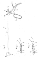
- Weitere Merkmale und Vorteile der Erfindung ergeben sich anhand der zugehörigen Zeichnung, in der zwei Ausführungsbeispiele einer erfindungsgemäßen medizinischen Stanze nur beispielhaft dargestellt sind, ohne die Erfindung auf diese Ausführungsbeispiele zu beschränken. In der Zeichnung zeigt:
- Fig. 1
- eine teilweise geschnittene Seitenansicht einer ersten Ausführungsform einer erfindungsgemäßen medizinischen Stanze;
- Fig. 2
- eine vergrößerte Ansicht des Details II gemäß
Fig. 1 ; - Fig. 3
- eine Ansicht gemäß
Fig. 2 , jedoch eine zweite Ausführungsform darstellend; - Fig. 4
- eine perspektivische Ansicht der Stanze gemäß
Fig. 1 , jedoch im zerlegten Zustand; - Fig. 5
- eine perspektivische Ansicht gemäß
Fig. 4 , jedoch die Stanze im zusammengesetzten Zustand darstellend; - Fig. 6
- eine vergrößerte Ansicht des Details VI gemäß
Fig. 5 - Fig. 7
- eine Seitenansicht der Detailansicht gemäß
Fig. 6 ; - Fig. 8
- eine vergrößerte Ansicht des Details VIII gemäß
Fig. 5 und - Fig. 9
- eine Seitenansicht der Detailansicht gemäß
Fig. 8 . - Die in den Abbildungen
Fig. 1, 3 ,4 und5 vollständig dargestellte medizinische Stanze 1 besteht im Wesentlichen aus einem als Hohlschaft ausgebildeten Schaft 2, an dessen proximalem Ende eine Handhabe 3 angeordnet ist, die aus einem starren Griffteil 4 und einem gegenüber dem starren Griffteil 4 verschwenkbaren Griffteil 5 besteht. Am distalen Ende des Schaftes 2 ist ein Stanzwerkzeug 6 angeordnet, das aus einer starren Schneidkante 7 und einer gegenüber der starren Schneidkante 7 verschiebbaren Schneidkante 8 besteht, wobei die verschiebbare Schneidkante 8 am distalen Ende einer verschiebbar im Hohlschaft 2 gelagerten hohlen Schub-/Zugstange 9 angeordnet ist. - Wie aus
Fig. 1 und 2 ersichtlich, stehen die verschiebbare Schneidkante 8 des Stanzwerkzeugs 6 und der verschwenkbare Griffteil 5 der Handhabe 3 über die im Hohlschaft 2 gelagerte, als Schub-/Zugstange 9 ausgebildete Schub-/Zugeinrichtung derart in Wirkverbindung miteinander, dass durch das Verstellen des verschwenkbaren Handgriffs 5 der Handhabe 3 die verschiebbare Schneidkante 8 über die Verlagerung des Schub-/Zugstange 9 in Richtung der Längsachse 10 des Schaftes 2 auf die starre Schneidkante 7 des Stanzwerkzeugs 6 zu bzw. umgekehrt von der starren Schneidkante 7 fort verschiebbar ist. - Bei der dargestellten Ausführungsform bewirkt das Zusammendrücken der Griffteile 4 und 5 der Handhabe 3 eine Verlagerung der Schub-/Zugstange 9 in distale Richtung und somit ein Verschieben der verschiebbaren Schneidkante 8 in Richtung der starren Schneidkante 7. Zwischen den beiden Griffteilen 4 und 5 der Handhabe 3 ist ein Federelement 11 angeordnet, welches die Griffteile 4 und 5 auseinanderdrückt und somit die Schub-/Zugstange 9 in proximale Richtung vorspannt, in der die verschiebbare Schneidkante 8 und die starre Schneidkante 7 am weitesten voneinander entfernt sind und die in
Fig. 2 und 3 dargestellten Positionen zueinander einnehmen. - Der Aufbau und die Anordnung der Schneidkanten 7 und 8 des Stanzwerkzeugs 6 ist insbesondere den Abbildungen
Fig. 2 und 3 zu entnehmen, die zwei Ausführungsbeispiele zur Ausgestaltung der Schneidkanten 7 und 8 zeigen. In beiden Fällen bildet die verschiebbare Schneidkante 8 das distale Ende der im Hohlschaft 2 verschiebbar gelagerten hohlen Schub-/Zugstange 9. - Zur Ausbildung der starren Schneidkante 7 ist im Bereich des distalen Endes des Hohlschaftes 2 eine radialwärts weisende Aussparung 12 im Hohlschaft 2 ausgebildet, deren nach proximal weisende Kante die starre Schneidkante 7 bildet.
- Die beiden dargestellten Ausführungsformen zur Ausgestaltung der starren und verschiebbaren Schneidkanten 7 und 8 unterscheiden sich voneinander durch die Ausrichtung der Schneidkanten 7 und 8 zur Längsachse 10 des Schaftes 2. Zueinander sind die Schneidkanten 7 und 8 bei beiden Ausführungsformen parallel ausgerichtet
- Wie aus
Fig. 1 und 2 ersichtlich, sind die starre Schneidkante 7 und die verschiebbare Schneidkante 8 bei der ersten Ausführungsform parallel zueinander und in einem vom rechten Winkel abweichenden Winkel, vorzugsweise einem Winkel von 45°, zur Längsachse 10 des Schaftes 2 ausgebildet. Bei der inFig. 3 dargestellten zweiten Ausführungsform sind die starre Schneidkante 7 und die verschiebbare Schneidkante 8 im Wesentlichen rechtwinklig zur Längsachse 10 des Schaftes 2 ausgebildet. - Das Montieren und Demontieren einer solchermaßen ausgebildeten medizinischen Stanze 1 wird nachfolgend insbesondere anhand der Abbildungen
Fig. 4 bis 9 beschrieben. - Zur Montage der medizinischen Stanze 1 wird ausgehend von dem in
Fig. 4 dargelegten zerlegten Zustand zunächst die hohle Schub-/Zugstange 9 vom proximalen Ende her in den Hohlschaft 2 eingeschoben und dann mit dem verschwenkbaren Griffteil 5 der Handhabe 3 derart gekoppelt, dass eine Betätigung des verschwenkbaren Griffteils 5 eine Längsverlagerung der Schub-/Zugstange 9 im Hohlschaft 2 bewirkt. - Bei der dargestellten Ausführungsform erfolgt das Festlegen der Schub-/Zugstange 9 am verschwenkbaren Griffteil 5 der Handhabe 3 über eine unverlierbar an der Schub-/Zugstange 9 gelagerte Überwurfmutter 13, die auf einen entsprechenden Gewindebereich 14 der Handhabe 3 aufgeschraubt wird. Selbstverständlich ist es auch möglich, die Überwurfmutter 13 an der Handhabe 3 zu lagern und den Gewindebereich am proximalen Ende der Schub-/Zugstange 9 auszubilden.
- Insbesondere bei der Ausbildung der Schneidkanten 7 und 8 des Stanzwerkzeugs 6 mit einem vom rechten Winkel abweichenden Winkel zur Längsachse 10 des Schaftes 2 ist es zwingend erforderlich, dass die die verschiebbare Schneidkante 8 tragende Schub-/Zugstange 9 in der richtigen Ausrichtung zur am Hohlschaft 2 ausgebildeten starren Schneidkante 7 in den Hohlschaft 2 eingeführt wird. Um ein lagerichtiges und richtig positioniertes Einführen der Schub-/Zugstange 9 in den Hohlschaft 2 zu gewährleisten, sind an der Schub-/Zugstange 9 und an der Handhabe 3 miteinander korrespondierende Positionierungselemente 15 ausgebildet, die eine Fehlpositionierung verhindern.
- Bei der dargestellten Ausführungsform sind die Positionierungselemente 15 als an der Schub-/Zugstange 9 ausgebildeter Stift 16 und an der Handhabe 3 ausgebildete Nut 17 zur Aufnahme des Stiftes 16 ausgebildet. Erst wenn der Stift 16 vollständig in die Nut 17 eingeschoben wurde, lässt sich die Überwurfmutter 13 zum Festlegen der Schub-/Zugstange 9 an der Handhabe 3 auf den Gewindebereich 14 aufschrauben. Selbstverständlich ist es auch möglich, die Ausbildung des Stiftes 16 und der Nut 17 am jeweils anderen Bauteil 3 und 9 vorzunehmen.
- Die durch die Positionierungselemente 15 bewirkte lagerichtige Ausrichtung der Schneidkanten 7 und 8 des Stanzwerkzeugs 6 zueinander ist insbesondere den Abbildungen
Fig. 6 bis Fig. 9 zu entnehmen. - Nach dem lagerichtigen Einführen der Schub-/Zugstange 9 in den Hohlschaft 9 und dem Festlegen der Schub-/Zugstange 9 am verschwenkbaren Griffteil 5 der Handhabe 3 mittels der Überwurfmutter 13 ist die medizinische Stanze 1 einsatzbereit.
- Die Demontage der medizinischen Stanze 1, beispielsweise zu Reinigungszwecken, erfolgt in umgekehrter Reihenfolge und wird durch das Abschrauben der Überwurfmutter 13 vom Gewindebereich 14 und somit das Lösen der Kopplung zwischen der Schub-/Zugstange 9 und der Handhabe 3 eingeleitet.
- Nachfolgend kann die Schub-/Zugstange über das proximale Ende des Schaftes 2 aus dem Hohlschaft 2 herausgezogen werden. Das Reinigen des Hohlschaftes 2 erfolgt beispielsweise über einen an der Handhabe 3 angeordneten Spülanschluss 18. Die aus dem Hohlschaft 2 herausgezogene Schub-/Zugstange 9 lässt sich als separates Bauteil ebenfalls einfach und gut reinigen.
- Eine solchermaßen ausgebildete medizinische Stanze 1 zeichnet sich dadurch aus, dass sie bei einfachem konstruktiven Aufbau einerseits die Herstellung sehr kleiner Schaftdurchmesser ermöglicht und andererseits gut zu reinigen ist.
-
- 1
- medizinische Stanze
- 2
- Schaft/Hohlschaft
- 3
- Handhabe
- 4
- starrer Griffteil
- 5
- verschwenkbarer Griffteil
- 6
- Stanzwerkzeug
- 7
- starre Schneidkante
- 8
- verschiebbare Schneidkante
- 9
- Schub-/Zugstange
- 10
- Längsachse
- 11
- Federelement
- 12
- Aussparung
- 13
- Überwurfmutter
- 14
- Gewindebereich
- 15
- Positionierungselemente
- 16
- Stift
- 17
- Nut
- 18
- Spülanschluss
Claims (10)
- Medizinische Stanze mit einem Hohlschaft (2), einem am distale Ende des Hohlschaftes (2) angeordneten, aus einer starren Schneidkante (7) und einer gegenüber der starren Schneidkante (7) verschiebbaren Schneidkante (8) bestehenden Stanzwerkzeug (6) sowie mit einer am proximalen Ende des Hohlschaftes (2) angeordneten Handhabe (3), wobei die verschiebbare Schneidkante (8) und die Handhabe (3) über eine verschiebbar in dem Hohlschaft (2) gelagerte, als Schub-/Zugstange (9) ausgebildete Schub-/Zugeinrichtung (9) miteinander in Wirkverbindung stehen,
dadurch gekennzeichnet,
dass die Schub-/Zugstange (9) als hohles Rohr ausgebildet ist, die über das proximale Ende des Hohlschaftes (2) in den Hohlschaft (2) einsetzbar und aus dem Hohlschaft (2) herausziehbar ist. - Medizinische Stanze nach Anspruch 1, dadurch gekennzeichnet, dass die Schub-/Zugstange (9) über eine Überwurfmutter (13) an der Handhabe (3) festlegbar ist.
- Medizinische Stanze nach Anspruch 1 oder 2, dadurch gekennzeichnet, dass an der Schub-/Zugstange (9) und an der Handhabe (3) miteinander korrespondierende Positionierungselemente (15) ausgebildet sind.
- Medizinische Stanze nach Anspruch 3, dadurch gekennzeichnet, dass die Positionierungselemente (15) als an einem Bauteil (3 oder 9) ausgebildeter Stift (16) und am anderen Bauteil (9 oder 3) ausgebildete Nut (17) zur Aufnahme des Stiftes (16) ausgebildet sind.
- Medizinische Stanze nach einem der Ansprüche 1 bis 4" dadurch gekennzeichnet, dass die starre Schneidkante (7) im Bereich des distalen Endes am Hohlschaft (2) ausgebildet ist.
- Medizinische Stanze nach Anspruch 5, dadurch gekennzeichnet, dass im Bereich des distalen Endes des Hohlschaftes (2) eine radialwärts weisende Aussparung (12) ausgebildet ist, deren nach proximal weisende Kante die starre Schneidkante (7) bildet.
- Medizinische Stanze nach einem der Ansprüche 1 bis 6, dadurch gekennzeichnet, dass die verschiebbare Schneidkante (8) das distale Ende der in dem Hohlschaft (2) gelagerten Schub-/Zugstange (9) bildet.
- Medizinische Stanze nach einem der Ansprüche 1 bis 7, dadurch gekennzeichnet, dass die starre Schneidkante (7) und die verschiebbare Schneidkante (8) parallel zueinander und im Wesentlichen rechtwinklig zur Längsachse (10) des Schaftes (2) ausgebildet sind.
- Medizinische Stanze nach einem der Ansprüche 1 bis 7, dadurch gekennzeichnet, dass die starre Schneidkante (7) und die verschiebbare Schneidkante (8) parallel zueinander und in einem vom rechten Winkel abweichenden Winkel, vorzugsweise von 45°, zur Längsachse (10) des Schaftes (2) ausgebildet sind.
- Medizinische Stanze nach einem der Ansprüche 1 bis 9, dadurch gekennzeichnet, dass die Handhabe (3) aus einem starren Griffteil (4) und einem gegenüber dem starren Griffteil (4) verschwenkbaren Griffteil (5) besteht, wobei die in dem Hohlschaft gelagerte Schub-/Zugstange (9) mit dem verschwenkbaren Griffteil (5) gekoppelt ist.
Applications Claiming Priority (1)
| Application Number | Priority Date | Filing Date | Title |
|---|---|---|---|
| DE102008026353A DE102008026353A1 (de) | 2008-05-31 | 2008-05-31 | Medizinische Stanze |
Publications (1)
| Publication Number | Publication Date |
|---|---|
| EP2127607A1 true EP2127607A1 (de) | 2009-12-02 |
Family
ID=41100611
Family Applications (1)
| Application Number | Title | Priority Date | Filing Date |
|---|---|---|---|
| EP09006874A Ceased EP2127607A1 (de) | 2008-05-31 | 2009-05-22 | Medizinische Stanze |
Country Status (3)
| Country | Link |
|---|---|
| US (1) | US20090299399A1 (de) |
| EP (1) | EP2127607A1 (de) |
| DE (1) | DE102008026353A1 (de) |
Citations (5)
| Publication number | Priority date | Publication date | Assignee | Title |
|---|---|---|---|---|
| DE3729513A1 (de) * | 1986-09-04 | 1988-03-10 | Ewald Hensler | Chirurgisches instrument insbesondere fuer die arthroskopie |
| DE4424659A1 (de) * | 1994-07-14 | 1996-01-18 | Waizenegger Klaus | Chirurgisches Instrument |
| US5766177A (en) * | 1996-04-02 | 1998-06-16 | Oceaneering International, Inc. | Rongeur |
| EP1055397A1 (de) | 1999-04-29 | 2000-11-29 | Karl Storz GmbH & Co. KG | Medizinisches Instrument zum Präparieren von Gewebe |
| EP1362556A1 (de) * | 1995-04-04 | 2003-11-19 | United States Surgical Corporation | Chirurgisches Schneidinstrument |
Family Cites Families (1)
| Publication number | Priority date | Publication date | Assignee | Title |
|---|---|---|---|---|
| DE2808911C2 (de) * | 1978-03-02 | 1979-11-08 | B. Braun Melsungen Ag, 3508 Melsungen | Stanze zum Abtragen von Knochen und Knorpel |
-
2008
- 2008-05-31 DE DE102008026353A patent/DE102008026353A1/de not_active Withdrawn
-
2009
- 2009-05-22 EP EP09006874A patent/EP2127607A1/de not_active Ceased
- 2009-05-29 US US12/474,914 patent/US20090299399A1/en not_active Abandoned
Patent Citations (5)
| Publication number | Priority date | Publication date | Assignee | Title |
|---|---|---|---|---|
| DE3729513A1 (de) * | 1986-09-04 | 1988-03-10 | Ewald Hensler | Chirurgisches instrument insbesondere fuer die arthroskopie |
| DE4424659A1 (de) * | 1994-07-14 | 1996-01-18 | Waizenegger Klaus | Chirurgisches Instrument |
| EP1362556A1 (de) * | 1995-04-04 | 2003-11-19 | United States Surgical Corporation | Chirurgisches Schneidinstrument |
| US5766177A (en) * | 1996-04-02 | 1998-06-16 | Oceaneering International, Inc. | Rongeur |
| EP1055397A1 (de) | 1999-04-29 | 2000-11-29 | Karl Storz GmbH & Co. KG | Medizinisches Instrument zum Präparieren von Gewebe |
Also Published As
| Publication number | Publication date |
|---|---|
| US20090299399A1 (en) | 2009-12-03 |
| DE102008026353A1 (de) | 2009-12-03 |
Similar Documents
| Publication | Publication Date | Title |
|---|---|---|
| EP1889578B1 (de) | Medizinisches Rohrschaftinstrument | |
| EP3442450B1 (de) | Instrument zum führen eines stabs in eine implantataufnahme | |
| DE102011100484B4 (de) | Klemmvorrichtung für Photovoltaik-Module | |
| EP3410965B1 (de) | Instrument zum führen eines stabs in eine implantataufnahme | |
| EP1400211B1 (de) | Endoskopisches Instrument mit abnehmbarem Werkzeugkopf | |
| DE102010011926A1 (de) | Laparoskopischer Nadelhalter | |
| DE29819914U1 (de) | Endoskopisches Einsetzinstrumentarium | |
| EP2523734B1 (de) | Trampolin | |
| EP0699054A1 (de) | Chirurgisches instrument mit zwei trennbaren griffbranchen | |
| DE102015223479A1 (de) | Handhabungsinstrument für eine Knochenschraube | |
| DE102009056099B4 (de) | Chirurgisches Instrument | |
| DE212023000434U1 (de) | Verbindungsvorrichtung und Endoskop-Verbindungssystem | |
| EP2371308B1 (de) | Medizinisches Instrument | |
| DE9421125U1 (de) | Chirurgische Zange, insbesondere Siebbeinzange | |
| DE202004020838U1 (de) | Chirurgisches Instrument | |
| EP3066997B1 (de) | Endoskopische vorrichtung | |
| DE102013107308A1 (de) | Stabeinsetzinstrument | |
| EP2258285B1 (de) | Medizinische Stanze | |
| EP3300675A1 (de) | Komponente für ein medizinisches instrument und medizinisches instrument | |
| DE102012007474A1 (de) | Haltevorrichtung | |
| DE4327233A1 (de) | Endoskopisches Setzgerät für chirurgische Instrumentenköpfe | |
| DE102018108088B4 (de) | Stabeinsetzinstrument | |
| DE102008026353A1 (de) | Medizinische Stanze | |
| WO1997038641A1 (de) | Knochenmarknagel | |
| DE102013211368A1 (de) | Endoskopisches Schaftinstrument |
Legal Events
| Date | Code | Title | Description |
|---|---|---|---|
| PUAI | Public reference made under article 153(3) epc to a published international application that has entered the european phase |
Free format text: ORIGINAL CODE: 0009012 |
|
| AK | Designated contracting states |
Kind code of ref document: A1 Designated state(s): AT BE BG CH CY CZ DE DK EE ES FI FR GB GR HR HU IE IS IT LI LT LU LV MC MK MT NL NO PL PT RO SE SI SK TR |
|
| 17P | Request for examination filed |
Effective date: 20100531 |
|
| 17Q | First examination report despatched |
Effective date: 20100623 |
|
| STAA | Information on the status of an ep patent application or granted ep patent |
Free format text: STATUS: THE APPLICATION HAS BEEN REFUSED |
|
| 18R | Application refused |
Effective date: 20111026 |