EP2127593A1 - Fluorescence monitoring apparatus - Google Patents
Fluorescence monitoring apparatus Download PDFInfo
- Publication number
- EP2127593A1 EP2127593A1 EP08722195A EP08722195A EP2127593A1 EP 2127593 A1 EP2127593 A1 EP 2127593A1 EP 08722195 A EP08722195 A EP 08722195A EP 08722195 A EP08722195 A EP 08722195A EP 2127593 A1 EP2127593 A1 EP 2127593A1
- Authority
- EP
- European Patent Office
- Prior art keywords
- fluorescence
- excitation light
- wavelength
- wavelength band
- excitation
- Prior art date
- Legal status (The legal status is an assumption and is not a legal conclusion. Google has not performed a legal analysis and makes no representation as to the accuracy of the status listed.)
- Withdrawn
Links
Images



Classifications
-
- A—HUMAN NECESSITIES
- A61—MEDICAL OR VETERINARY SCIENCE; HYGIENE
- A61B—DIAGNOSIS; SURGERY; IDENTIFICATION
- A61B5/00—Measuring for diagnostic purposes; Identification of persons
- A61B5/0059—Measuring for diagnostic purposes; Identification of persons using light, e.g. diagnosis by transillumination, diascopy, fluorescence
- A61B5/0071—Measuring for diagnostic purposes; Identification of persons using light, e.g. diagnosis by transillumination, diascopy, fluorescence by measuring fluorescence emission
-
- A—HUMAN NECESSITIES
- A61—MEDICAL OR VETERINARY SCIENCE; HYGIENE
- A61B—DIAGNOSIS; SURGERY; IDENTIFICATION
- A61B1/00—Instruments for performing medical examinations of the interior of cavities or tubes of the body by visual or photographical inspection, e.g. endoscopes; Illuminating arrangements therefor
- A61B1/00002—Operational features of endoscopes
- A61B1/00004—Operational features of endoscopes characterised by electronic signal processing
- A61B1/00009—Operational features of endoscopes characterised by electronic signal processing of image signals during a use of endoscope
-
- A—HUMAN NECESSITIES
- A61—MEDICAL OR VETERINARY SCIENCE; HYGIENE
- A61B—DIAGNOSIS; SURGERY; IDENTIFICATION
- A61B1/00—Instruments for performing medical examinations of the interior of cavities or tubes of the body by visual or photographical inspection, e.g. endoscopes; Illuminating arrangements therefor
- A61B1/00163—Optical arrangements
- A61B1/00186—Optical arrangements with imaging filters
-
- A—HUMAN NECESSITIES
- A61—MEDICAL OR VETERINARY SCIENCE; HYGIENE
- A61B—DIAGNOSIS; SURGERY; IDENTIFICATION
- A61B1/00—Instruments for performing medical examinations of the interior of cavities or tubes of the body by visual or photographical inspection, e.g. endoscopes; Illuminating arrangements therefor
- A61B1/04—Instruments for performing medical examinations of the interior of cavities or tubes of the body by visual or photographical inspection, e.g. endoscopes; Illuminating arrangements therefor combined with photographic or television appliances
- A61B1/043—Instruments for performing medical examinations of the interior of cavities or tubes of the body by visual or photographical inspection, e.g. endoscopes; Illuminating arrangements therefor combined with photographic or television appliances for fluorescence imaging
-
- A—HUMAN NECESSITIES
- A61—MEDICAL OR VETERINARY SCIENCE; HYGIENE
- A61B—DIAGNOSIS; SURGERY; IDENTIFICATION
- A61B1/00—Instruments for performing medical examinations of the interior of cavities or tubes of the body by visual or photographical inspection, e.g. endoscopes; Illuminating arrangements therefor
- A61B1/06—Instruments for performing medical examinations of the interior of cavities or tubes of the body by visual or photographical inspection, e.g. endoscopes; Illuminating arrangements therefor with illuminating arrangements
- A61B1/0638—Instruments for performing medical examinations of the interior of cavities or tubes of the body by visual or photographical inspection, e.g. endoscopes; Illuminating arrangements therefor with illuminating arrangements providing two or more wavelengths
-
- A—HUMAN NECESSITIES
- A61—MEDICAL OR VETERINARY SCIENCE; HYGIENE
- A61B—DIAGNOSIS; SURGERY; IDENTIFICATION
- A61B5/00—Measuring for diagnostic purposes; Identification of persons
- A61B5/0059—Measuring for diagnostic purposes; Identification of persons using light, e.g. diagnosis by transillumination, diascopy, fluorescence
- A61B5/0082—Measuring for diagnostic purposes; Identification of persons using light, e.g. diagnosis by transillumination, diascopy, fluorescence adapted for particular medical purposes
- A61B5/0084—Measuring for diagnostic purposes; Identification of persons using light, e.g. diagnosis by transillumination, diascopy, fluorescence adapted for particular medical purposes for introduction into the body, e.g. by catheters
Definitions
- the present invention relates to a fluorescence imaging apparatus.
- the endoscope disclosed in Patent Document 2 is capable of observation using a plurality of kinds of light without employing spectral means such as a dichroic mirror, and therefore, a plurality of image-acquisition optical systems are disposed at the tip of the insertion portion of the endoscope.
- fluorescent probes that emit light upon binding to material in a living organism; and by administering the living organism with a fluorescent probe that binds to a material related to a lesion and observing the fluorescence therefrom, it is possible to obtain information about the lesion.
- fluorescence in multiple wavelength bands may be excited with one kind of excitation light. In this case, it is possible to more precisely observe the state of the living organism by separating and detecting the fluorescences.
- material that absorbs light is also present in biological tissue, in addition to the material that emits fluorescence, there is a problem in that it is not possible to precisely detect the distribution of the fluorescent material due to the distribution of this absorbing material.
- the present invention has been conceived in light of the circumstances described above, and an object thereof is to provide a fluorescence imaging apparatus that can precisely detect the distribution of abnormal tissue, such as lesions, in an observed object regardless of the distribution of absorbing material present in a living organism.
- a fluorescence imaging apparatus including an excitation-light radiating unit that irradiates an observed object with excitation light of a plurality of wavelengths; a filter that transmits fluorescence in a specific wavelength band from among fluorescence produced from the observed object in response to the excitation light radiated from the excitation-light radiating unit; a light detector that detects the fluorescence transmitted through the filter; and a computing unit that calculates a fluorescence intensity ratio in the same wavelength band in response to the excitation light of the plurality of wavelengths, which is detected by the light detector.
- the filter may transmit fluorescence of a plurality of wavelength bands, and the computing unit may calculate the fluorescence intensity ratio in each wavelength band.
- the filter may be formed of a variable spectrum element that can change the wavelength band at which the fluorescence is transmitted.
- the above-described aspect may be configured such that the wavelength of at least one kind of excitation light of the excitation light of the plurality of wavelengths is contained in a wavelength band between a maximum-excitation wavelength of a first substance excited by the excitation light and a maximum-excitation wavelength of a second substance that differs from the first substance.
- the first substance may be collagen or NADH
- the second substance may be FAD.
- the wavelength of at least one kind of excitation light in the excitation light of the plurality of wavelengths may contain a wavelength with a middle value between the maximum-excitation wavelength of the first substance excited by the excitation light and the maximum-excitation wavelength of the second substance that differs from the first substance.
- the pass band of the filter that transmits the fluorescence with a specific wavelength band may contain a wavelength at which the fluorescence intensity of collagen, NADH, FAD, or porphyrin is maximized.
- variable spectrum element may shift a transmission band that is narrower than the wavelength band for detecting fluorescence
- the computing unit may calculate the ratio using integrated values of the fluorescence intensities detected by the light detector at each shifted position of the transmission band.
- the computing unit may calculate the fluorescence intensity ratio according to the following expression.
- EM1ex1 is the fluorescence intensity in response to the first excitation light, in a first wavelength band
- EM1ex2 is the fluorescence intensity in response to second excitation light, in the first wavelength band
- EM2ex2 is the fluorescence intensity in response to the second excitation light, in a second wavelength band
- EM2ex3 is the fluorescence intensity in response to the third excitation light, in the second wavelength band.
- the above-described aspect may further comprise a display unit that displays a distribution of results calculated by the computing unit on the basis of the fluorescence from each part of the observed object.
- the display unit may display the results calculated by the computing unit in a conspicuous fashion.
- the present invention affords an advantage in that it is possible to precisely detect the distribution of abnormal tissue, such as lesions, in an observed object regardless of the distribution of absorbing material that is present in a living organism.
- a fluorescence imaging apparatus 1 includes a light source unit 2 that can emit white light and excitation light of two wavelengths in a switching fashion, an elongated insertion portion 3 that is inserted inside a body cavity, an image-acquisition unit 4 provided in the insertion portion 3, a signal processing unit 5 that processes fluorescence image information detected by the image-acquisition unit 4, and a display unit 6 that displays the output signal from the signal processing unit 5.
- the insertion unit 3 has extremely narrow outer dimensions allowing it to be inserted into the body cavity of a living organism and is provided, in the interior thereof, with the image-acquisition unit 4 and a light guide 12 that conveys light from the light source unit 2 to a tip 3a thereof.
- the image-acquisition unit 4 is provided with an objective lens 13 that collects light incident from the observed object, a fluorescence filter 14 that transmits fluorescence in a specific wavelength band from the light collected by the objective lens 13, and an image-acquisition device 15 that acquires the fluorescence transmitted through the fluorescence filter 14 and converts it to an electrical signal.
- the transmission wavelength band of the fluorescence filter 14 is set from 450 nm to 500 nm, inclusive, as shown in Fig. 2 .
- the signal processing unit 5 includes a video-signal processing unit 16 that generates one reflected-light image and two fluorescence images on the basis of reflected-light intensity information and fluorescence intensity information for both types of excitation light from each part of the observed object, which information is input from the image-acquisition unit 4; a first frame memory 17 that stores the image information generated in the video-signal processing unit 16; a computing unit 18 that performs division processing using the two fluorescence images stored in the first frame memory 17; a second frame memory 19 that stores the respective fluorescence image information subjected to division processing by the computing unit 18 and the reflected-light image; a display processing unit 20 that performs white balance processing on the reflected-light image stored in the second frame memory 19 and that performs superimposition processing on the reflected-light image and the fluorescence images; and an encoder 21 that encodes the superimposed image information and outputs it to the display unit 6.
- a video-signal processing unit 16 that generates one reflected-light image and two fluorescence images on the basis of
- the ratio (EM1ex1/EM1ex2) of the intensity EM1ex1 of the fluorescence transmitted through the fluorescence filter 14 from among the fluorescence produced by the observed object upon irradiation with the first excitation light emitted from the first laser light source and the intensity EM1ex2 of the fluorescence transmitted through the fluorescence filter 14 from the fluorescence produced by the observed object upon irradiation with the second excitation light emitted from the second laser light source is calculated in the computing unit 18.
- the white light source 9 in the light source unit 2 is operated, the insertion portion 2 is inserted into the body cavity, and while checking the reflected-light image, the tip 2a of the insertion portion 2 is placed facing the observation target site in the body cavity.
- the first excitation light and the second excitation light are sequentially emitted from the light source unit 2, and the observation target site in the body cavity is irradiated with the first and second excitation light conveyed via the light guide 12.
- Reduced nicotinamide nucleotide (NADH), flavin adenine nucleotide (FAD), collagen etc. which are naturally occurring autofluorescent substances, are present in biological tissue, and they emit fluorescence due to excitation light from about 300 nm to 500 nm, inclusive. Also, reduced nicotinamide nucleotide (NADH) and collagen show maximum fluorescence intensity due to excitation light of about 340 nm, and flavin adenine nucleotide (FAD) does so at about 450 nm.
- the maximum-excitation wavelength of reduced nicotinamide nucleotide (NADH) and collagen is 340 nm
- the maximum-excitation wavelength of flavin adenine nucleotide (FAD) is 450 nm.
- nicotinamide nucleotide (NADH), collagen etc. are excited upon irradiation with the first excitation light, and mainly flavin adenine nucleotide (FAD) etc. is excited upon irradiation with the second excitation light, emitting their respective fluorescences.
- Fig. 2 shows wavelength characteristics of the excitation light and fluorescence, as well as the transmittance characteristic of the fluorescence filter 14.
- the fluorescence produced has a fluorescence spectrum covering a wide range; however, because the fluorescence filter 14 is provided, only fluorescence in the wavelength range from 450 nm to 500 nm, inclusive, contained therein is captured by the image-acquisition device.
- the fluorescence produced in the observed object in response to each type of excitation light is input to the video-signal processing unit 16, is structured as two-dimensional fluorescence image information having fluorescence intensity information at each pixel, and is stored in the first frame memory 17.
- the two sets of fluorescence image information of the same wavelength band, in response to the excitation light of different wavelengths, which are stored in the first frame memory 17, are subjected to computational processing in the computing unit 18, thereby calculating the fluorescence intensity ratio at each pixel.
- the reflected-light image stored in the first frame memory 17 is sent, without processing, to the second frame memory 19.
- the fluorescence image information subjected to division processing and the reflected-light image are stored in the second frame memory 19. Then, the reflected-light image stored in the second frame memory 19 is subjected to white-balance processing by the display processing unit 20, and after being superimposed with the fluorescence image stored in the second frame memory 19, it is encoded by the encoder 21 and output to the display unit 6, where it is displayed.
- the intensities of the two kinds of fluorescence in the transmission wavelength band of the fluorescence filter 14, emitted from the observed object in response to the excitation light of two different wavelengths differ; however, the fluorescences in the same wavelength band at the same position on the observed object are similarly absorbed by absorbing material present in the observed object because the illumination conditions of the excitation light are the same.
- a fluorescence imaging apparatus 30 according to a second embodiment of the present invention will be described below with reference to Figs. 3 to 8 .
- parts having the same configuration as those in the fluorescence imaging apparatus 1 according to the first embodiment described above are assigned the same reference numerals, and a description thereof is omitted.
- the fluorescence imaging apparatus 30 differs from the fluorescence imaging apparatus 1 according to the first embodiment in that a light source unit 31 has first to third laser light sources 32 to 34, an etalon-type variable spectrum element 35 such as that shown in Fig. 4 is employed instead of the fluorescence filter 14, and a distance-signal processing unit 36 and a control unit 37 for the variable spectrum element 35 are provided in the signal processing unit 5.
- Wavelength ⁇ 2 is set to fall in the wavelength band between the maximum-excitation wavelength of NADH or collagen and the maximum-excitation wavelength of FAD.
- 400 nm which is a wavelength approximately in the middle of the these two maximum-excitation wavelengths, is selected as the wavelength of the second excitation light radiated from the second laser light source 33.
- the variable spectrum element 35 includes two optical substrates 35b that face each other with a distance therebetween and that are provided with reflective films 35a on the opposing surfaces, actuators 35c that change the distance between these optical substrates 35b, and sensors 38 provided on the opposing surfaces of the optical substrates 35b.
- the actuators 35c are formed of, for example, piezoelectric devices, and a plurality of them are provided at intervals in the circumferential direction of the optical substrates 35b.
- the sensors 38 include mutually opposing sensor electrodes 38a, and the distance between the optical substrates 35b is detected by detecting a change in electrostatic capacitance formed between the sensor electrodes 38a.
- the variable spectrum element 35 has a wavelength characteristic having a fixed transmission band and a variable transmission band.
- the fixed transmission band is set in a wavelength band from 450 nm to 500 nm, inclusive, to always allow passage of fluorescence in this wavelength band.
- the variable transmission band is set, for example, in a wavelength band from 500 nm to 650 nm, inclusive, and by changing the distance between the optical substrates 35b by operating the actuators 35c, it is possible to shift the transmission band, having a suitably narrow width relative to the entire wavelength band.
- the distance-signal processing unit 36 provided in the signal processing unit 5 amplifies the detected signal received from the sensor electrodes 38a and subjects the amplified signal to noise-removal processing and A/D conversion.
- the control unit 37 obtains the distance between the optical substrates 35b on the basis of the signal input from the distance-signal processing unit 36 and outputs a command signal to the actuators 35c so that the distance becomes a desired distance.
- the control unit 37 gradually varies the distance between the optical substrates 35b, thus gradually shifting the transmission band in the variable transmission band.
- the video-signal processing unit 16 stores the fluorescence intensities obtained by respectively radiating the first to third excitation light in the first frame memory 17 without processing.
- the values obtained by integrating, at each pixel, the fluorescence intensities acquired during shifting of the transmission band in the second wavelength band while respectively radiating the first to third excitation light are stored in the first frame memory 17 as the fluorescence image information EM2ex1, EM2ex2, and EM2ex3 for the wavelength band from 500 nm to 600 nm, inclusive, by taking the differences with respect to the fluorescence image information EM1ex1, EM1ex2, and EM1ex3.
- the values obtained by integrating, at each pixel, the fluorescence intensities acquired during shifting of the transmission band in the third wavelength band while respectively radiating the first to third excitation light are stored in the first frame memory 17 as the fluorescence image information EM3ex1, EM3ex2, and EM3ex3 for the wavelength band from 600 nm to 650 nm, inclusive, by taking the differences with respect to the fluorescence image information EM1ex1, EM1ex2, and EM1ex3.
- the fluorescence image information ratios calculated in the computing unit 18 are stored in the second frame memory 19, are subjected to superimposition processing by the display processing unit 20, and are displayed by the display unit 6, via the encoder 21.
- the display method for example, as shown in Fig. 8 , it is preferable to draw the contour of each region, or to change the color thereof, so that the region of each fluorescence image information ratio is made distinct.
- the ratio of the fluorescence intensities produced when exciting with excitation light of different wavelengths is calculated, and in each respective wavelength band, it is possible to acquire a fluorescence image in which the influence of absorption due to an absorbing material is eliminated at each position in the image. Accordingly, it is possible to more precisely distinguish between a normal area and a lesion.
- the fluorescence image information ratio (EM3ex2/EM3ex1) ⁇ (EM3ex2/EM3ex3) is calculated and displayed. Accordingly, the lesion is emphasized; instead of this, however, either (EM3ex2/EM3ex1) or (EM3ex2/EM3ex3) may be calculated and displayed.
- EM ⁇ 1 ⁇ ex ⁇ 1 / EM ⁇ 1 ⁇ ex ⁇ 2 / EM ⁇ 2 ⁇ ex ⁇ 3 / EM ⁇ 2 ⁇ ex ⁇ 2 and EM ⁇ 3 ⁇ ex ⁇ 2 / EM ⁇ 3 ⁇ ex ⁇ 1 > 1 and EM ⁇ 3 ⁇ ex ⁇ 2 / EM ⁇ 3 ⁇ ex ⁇ 3 > 1 may be displayed as operators.
- the light source for exciting fluorescence besides a laser light source, an LED or a combination of a white-light source and a bandpass filter may be used, and for the fluorescence transmission band, a plurality of bandpass filters may be used.
- Fig. 9A shows wavelength characteristics of the fluorescence from a normal area when irradiated with the first to third excitation light
- Fig. 9B shows wavelength characteristics of the fluorescence from a lesion when irradiated with the first to third excitation light.
- D 1 and d 1 reference signs
Landscapes
- Life Sciences & Earth Sciences (AREA)
- Health & Medical Sciences (AREA)
- Surgery (AREA)
- Engineering & Computer Science (AREA)
- Biophysics (AREA)
- Public Health (AREA)
- Veterinary Medicine (AREA)
- Physics & Mathematics (AREA)
- Pathology (AREA)
- General Health & Medical Sciences (AREA)
- Animal Behavior & Ethology (AREA)
- Biomedical Technology (AREA)
- Heart & Thoracic Surgery (AREA)
- Medical Informatics (AREA)
- Molecular Biology (AREA)
- Radiology & Medical Imaging (AREA)
- Optics & Photonics (AREA)
- Nuclear Medicine, Radiotherapy & Molecular Imaging (AREA)
- Signal Processing (AREA)
- Investigating, Analyzing Materials By Fluorescence Or Luminescence (AREA)
- Endoscopes (AREA)
- Medicines Containing Antibodies Or Antigens For Use As Internal Diagnostic Agents (AREA)
Abstract
Description
- The present invention relates to a fluorescence imaging apparatus.
- In endoscopic observation of living organisms using an endoscope system, in order to precisely observe the state of the living organism, it is preferable to implement an observation method utilizing a plurality of kinds of light with different spectral characteristics.
Endoscopes that are capable of observation using a plurality of kinds of light with different spectral characteristics are disclosed in Patent Document 1 andPatent Document 2. - With the endoscope disclosed in Patent Document 1, in order to acquire a plurality of kinds of images by using the plurality of kinds of light with different spectral characteristics in the same endoscope, light from the acquired object is spectrally separated by a dichroic mirror. Because it is difficult to build the dichroic mirror into the tip of an insertion portion of the endoscope, it is disposed outside the body, and it is thus necessary to convey the light from the acquired object, which is received at the tip of the insertion portion, to the dichroic mirror outside the body via a fiber bundle.
- The endoscope disclosed in
Patent Document 2 is capable of observation using a plurality of kinds of light without employing spectral means such as a dichroic mirror, and therefore, a plurality of image-acquisition optical systems are disposed at the tip of the insertion portion of the endoscope. - Furthermore, from commercially available fluorescent agents, it is possible to produce fluorescent probes that emit light upon binding to material in a living organism; and by administering the living organism with a fluorescent probe that binds to a material related to a lesion and observing the fluorescence therefrom, it is possible to obtain information about the lesion.
-
- Patent Document 1: Publication of Japanese Patent No.
3683271 - Patent Document 2: Japanese Unexamined Patent Application, Publication No.
2001-190489 - When observing autofluorescence from an autofluorescent substance that is naturally present in biological tissue, fluorescence in multiple wavelength bands may be excited with one kind of excitation light. In this case, it is possible to more precisely observe the state of the living organism by separating and detecting the fluorescences.
However, because material that absorbs light is also present in biological tissue, in addition to the material that emits fluorescence, there is a problem in that it is not possible to precisely detect the distribution of the fluorescent material due to the distribution of this absorbing material. - The present invention has been conceived in light of the circumstances described above, and an object thereof is to provide a fluorescence imaging apparatus that can precisely detect the distribution of abnormal tissue, such as lesions, in an observed object regardless of the distribution of absorbing material present in a living organism.
- In order to realize the above-described object, the present invention provides the following solutions.
One aspect of a fluorescence imaging apparatus according to the present invention is a fluorescence imaging apparatus including an excitation-light radiating unit that irradiates an observed object with excitation light of a plurality of wavelengths; a filter that transmits fluorescence in a specific wavelength band from among fluorescence produced from the observed object in response to the excitation light radiated from the excitation-light radiating unit; a light detector that detects the fluorescence transmitted through the filter; and a computing unit that calculates a fluorescence intensity ratio in the same wavelength band in response to the excitation light of the plurality of wavelengths, which is detected by the light detector. - In the above-described aspect, the filter may transmit fluorescence of a plurality of wavelength bands, and the computing unit may calculate the fluorescence intensity ratio in each wavelength band.
In the above-described aspect, the filter may be formed of a variable spectrum element that can change the wavelength band at which the fluorescence is transmitted. - The above-described aspect may be configured such that the wavelength of at least one kind of excitation light of the excitation light of the plurality of wavelengths is contained in a wavelength band between a maximum-excitation wavelength of a first substance excited by the excitation light and a maximum-excitation wavelength of a second substance that differs from the first substance.
- In the above-described aspect, the first substance may be collagen or NADH, and the second substance may be FAD.
In the above-described aspect, the wavelength of at least one kind of excitation light in the excitation light of the plurality of wavelengths may contain a wavelength with a middle value between the maximum-excitation wavelength of the first substance excited by the excitation light and the maximum-excitation wavelength of the second substance that differs from the first substance. - In the above-described aspect, the pass band of the filter that transmits the fluorescence with a specific wavelength band may contain a wavelength at which the fluorescence intensity of collagen, NADH, FAD, or porphyrin is maximized.
- In the above-described aspect, the variable spectrum element may shift a transmission band that is narrower than the wavelength band for detecting fluorescence, and the computing unit may calculate the ratio using integrated values of the fluorescence intensities detected by the light detector at each shifted position of the transmission band.
- In the above-described aspect, the computing unit may calculate the fluorescence intensity ratio according to the following expression.

- The above-described aspect may further comprise a display unit that displays a distribution of results calculated by the computing unit on the basis of the fluorescence from each part of the observed object.
In the above-described aspect, the display unit may display the results calculated by the computing unit in a conspicuous fashion. - The present invention affords an advantage in that it is possible to precisely detect the distribution of abnormal tissue, such as lesions, in an observed object regardless of the distribution of absorbing material that is present in a living organism.
-
- [
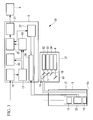
FIG. 1] Fig. 1 is a diagram showing the overall configuration of a fluorescence imaging apparatus according to a first embodiment of the present invention. - [
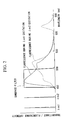
FIG. 2] Fig. 2 is a diagram showing an example of the transmittance characteristic of a bandpass filter and wavelength characteristics of excitation light and fluorescence in the fluorescence imaging apparatus inFig. 1 . - [
FIG. 3] Fig. 3 is a diagram showing the overall configuration of a fluorescence imaging apparatus according to a second embodiment of the present invention. - [
FIG. 4] Fig. 4 is a longitudinal sectional view showing a variable spectrum element provided in the fluorescence imaging apparatus inFig. 3 . - [
FIG. 5] Fig. 5 is a diagram showing an example of the transmittance characteristic of the variable spectrum element inFig. 4 , and the wavelength characteristics of first excitation light and fluorescence in response thereto. - [
FIG. 6] Fig. 6 is a diagram showing an example of the transmittance characteristic of the variable spectrum element inFig. 4 , and the wavelength characteristics of second excitation light and fluorescence in response thereto. - [
FIG. 7] Fig. 7 is a diagram showing an example of the transmittance characteristic of the variable spectrum element inFig. 4 , and the wavelength characteristics of third excitation light and fluorescence in response thereto. - [
FIG. 8] Fig. 8 is a diagram showing an example of a fluorescence image displayed by the fluorescence imaging apparatus inFig. 3 . - [
FIG. 9A] Fig. 9A is a diagram showing an example of the transmittance characteristic of the variable spectrum element and the wavelength characteristics of fluorescence from a normal area in response to the first to third excitation light, for explaining a modification of the fluorescence imaging apparatus inFig. 3 . - [
FIG. 9B] Fig. 9B is a diagram showing an example of the transmittance characteristic of the variable spectrum element and the wavelength characteristics of fluorescence from a lesion in response to the first to third excitation light, for explaining a modification of the fluorescence imaging apparatus inFig. 3 . -
- 1,30:
- fluorescence imaging apparatus
- 2:
- light source unit (excitation-light radiating unit)
- 12:
- light guide (excitation-light radiating unit)
- 14:
- bandpass filter (filter, fluorescence filter)
- 15:
- image-acquisition device (light detector)
- 18:
- computing unit
- 35:
- variable spectrum element (filter)
- A fluorescence imaging apparatus 1 according to a first embodiment of the present invention will be described below with reference to
Fig. 1 andFig. 2 .
A fluorescence imaging apparatus 1 according to this embodiment includes alight source unit 2 that can emit white light and excitation light of two wavelengths in a switching fashion, anelongated insertion portion 3 that is inserted inside a body cavity, an image-acquisition unit 4 provided in theinsertion portion 3, asignal processing unit 5 that processes fluorescence image information detected by the image-acquisition unit 4, and adisplay unit 6 that displays the output signal from thesignal processing unit 5. - The light-
source unit 2 is provided with a firstlaser light source 7 that emits first excitation light with a wavelength λ1 = 380 nm, a secondlaser light source 8 that emits second excitation light with a wavelength λ2 = 430 nm, awhite light source 9 that emits white light, and amirror 10 anddichroic mirror 11 that combine these into the same optical path. - The
insertion unit 3 has extremely narrow outer dimensions allowing it to be inserted into the body cavity of a living organism and is provided, in the interior thereof, with the image-acquisition unit 4 and alight guide 12 that conveys light from thelight source unit 2 to atip 3a thereof.
The image-acquisition unit 4 is provided with anobjective lens 13 that collects light incident from the observed object, afluorescence filter 14 that transmits fluorescence in a specific wavelength band from the light collected by theobjective lens 13, and an image-acquisition device 15 that acquires the fluorescence transmitted through thefluorescence filter 14 and converts it to an electrical signal.
The transmission wavelength band of thefluorescence filter 14 is set from 450 nm to 500 nm, inclusive, as shown inFig. 2 . - The
signal processing unit 5 includes a video-signal processing unit 16 that generates one reflected-light image and two fluorescence images on the basis of reflected-light intensity information and fluorescence intensity information for both types of excitation light from each part of the observed object, which information is input from the image-acquisition unit 4; afirst frame memory 17 that stores the image information generated in the video-signal processing unit 16; acomputing unit 18 that performs division processing using the two fluorescence images stored in thefirst frame memory 17; asecond frame memory 19 that stores the respective fluorescence image information subjected to division processing by thecomputing unit 18 and the reflected-light image; adisplay processing unit 20 that performs white balance processing on the reflected-light image stored in thesecond frame memory 19 and that performs superimposition processing on the reflected-light image and the fluorescence images; and anencoder 21 that encodes the superimposed image information and outputs it to thedisplay unit 6. - The ratio (EM1ex1/EM1ex2) of the intensity EM1ex1 of the fluorescence transmitted through the
fluorescence filter 14 from among the fluorescence produced by the observed object upon irradiation with the first excitation light emitted from the first laser light source and the intensity EM1ex2 of the fluorescence transmitted through thefluorescence filter 14 from the fluorescence produced by the observed object upon irradiation with the second excitation light emitted from the second laser light source is calculated in thecomputing unit 18. - The operation of the thus-configured fluorescence imaging apparatus 1 according to this embodiment is described below.
To observe biological tissue using the fluorescence imaging apparatus 1 according to this embodiment, first, thewhite light source 9 in thelight source unit 2 is operated, theinsertion portion 2 is inserted into the body cavity, and while checking the reflected-light image, the tip 2a of theinsertion portion 2 is placed facing the observation target site in the body cavity. In this state, the first excitation light and the second excitation light are sequentially emitted from thelight source unit 2, and the observation target site in the body cavity is irradiated with the first and second excitation light conveyed via thelight guide 12. - Reduced nicotinamide nucleotide (NADH), flavin adenine nucleotide (FAD), collagen etc., which are naturally occurring autofluorescent substances, are present in biological tissue, and they emit fluorescence due to excitation light from about 300 nm to 500 nm, inclusive. Also, reduced nicotinamide nucleotide (NADH) and collagen show maximum fluorescence intensity due to excitation light of about 340 nm, and flavin adenine nucleotide (FAD) does so at about 450 nm. In other words, the maximum-excitation wavelength of reduced nicotinamide nucleotide (NADH) and collagen is 340 nm, and the maximum-excitation wavelength of flavin adenine nucleotide (FAD) is 450 nm.
- Therefore, mainly reduced nicotinamide nucleotide (NADH), collagen etc. are excited upon irradiation with the first excitation light, and mainly flavin adenine nucleotide (FAD) etc. is excited upon irradiation with the second excitation light, emitting their respective fluorescences.
Fig. 2 shows wavelength characteristics of the excitation light and fluorescence, as well as the transmittance characteristic of thefluorescence filter 14. - As shown in
Fig. 2 , the fluorescence produced has a fluorescence spectrum covering a wide range; however, because thefluorescence filter 14 is provided, only fluorescence in the wavelength range from 450 nm to 500 nm, inclusive, contained therein is captured by the image-acquisition device. In other words, the fluorescence produced in the observed object in response to each type of excitation light is input to the video-signal processing unit 16, is structured as two-dimensional fluorescence image information having fluorescence intensity information at each pixel, and is stored in thefirst frame memory 17. - Then, the two sets of fluorescence image information of the same wavelength band, in response to the excitation light of different wavelengths, which are stored in the
first frame memory 17, are subjected to computational processing in thecomputing unit 18, thereby calculating the fluorescence intensity ratio at each pixel. The reflected-light image stored in thefirst frame memory 17 is sent, without processing, to thesecond frame memory 19. - The fluorescence image information subjected to division processing and the reflected-light image are stored in the
second frame memory 19. Then, the reflected-light image stored in thesecond frame memory 19 is subjected to white-balance processing by thedisplay processing unit 20, and after being superimposed with the fluorescence image stored in thesecond frame memory 19, it is encoded by theencoder 21 and output to thedisplay unit 6, where it is displayed. - With the fluorescence imaging apparatus 1 according to this embodiment, as shown in
Fig. 2 , the intensities of the two kinds of fluorescence in the transmission wavelength band of thefluorescence filter 14, emitted from the observed object in response to the excitation light of two different wavelengths, differ; however, the fluorescences in the same wavelength band at the same position on the observed object are similarly absorbed by absorbing material present in the observed object because the illumination conditions of the excitation light are the same. - Therefore, by calculating the fluorescence intensity ratio at each pixel using these two sets of fluorescence image information, it is possible to eliminate the influence of absorption due to the absorbing material.
In other words, at a lesion whose naturally bright fluorescence intensity is to be acquired, it was difficult to distinguish between a lesion and a normal area in a fluorescence image due to single excitation light because the fluorescence intensity is reduced due to the influence of the absorbing material; however, with the fluorescence imaging apparatus 1 according to this embodiment, the influence of the absorbing material can be removed, enabling accurate distinction between a lesion and a normal area. Therefore, an advantage is afforded in that the diagnostic ability can be enhanced. As the light source that excites fluorescence, besides a laser light source, an LED or a combination of a white-light source and a bandpass filter may also be used. - Next, a
fluorescence imaging apparatus 30 according to a second embodiment of the present invention will be described below with reference toFigs. 3 to 8 .
In the description of this embodiment, parts having the same configuration as those in the fluorescence imaging apparatus 1 according to the first embodiment described above are assigned the same reference numerals, and a description thereof is omitted. - As shown in
Fig. 3 , thefluorescence imaging apparatus 30 according to this embodiment differs from the fluorescence imaging apparatus 1 according to the first embodiment in that alight source unit 31 has first to thirdlaser light sources 32 to 34, an etalon-typevariable spectrum element 35 such as that shown inFig. 4 is employed instead of thefluorescence filter 14, and a distance-signal processing unit 36 and acontrol unit 37 for thevariable spectrum element 35 are provided in thesignal processing unit 5. - The first
laser light source 32 emits first excitation light with a wavelength λ1 = 380 nm. The secondlaser light source 33 emits second excitation light with a wavelength λ2 = 400 nm. The thirdlaser light source 34 emits third excitation light with a wavelength λ3 = 430 nm.
Wavelength λ2 is set to fall in the wavelength band between the maximum-excitation wavelength of NADH or collagen and the maximum-excitation wavelength of FAD. In this embodiment, as a particularly preferable example, 400 nm, which is a wavelength approximately in the middle of the these two maximum-excitation wavelengths, is selected as the wavelength of the second excitation light radiated from the secondlaser light source 33. - As shown in
Fig. 4 , thevariable spectrum element 35 includes twooptical substrates 35b that face each other with a distance therebetween and that are provided withreflective films 35a on the opposing surfaces,actuators 35c that change the distance between theseoptical substrates 35b, andsensors 38 provided on the opposing surfaces of theoptical substrates 35b. Theactuators 35c are formed of, for example, piezoelectric devices, and a plurality of them are provided at intervals in the circumferential direction of theoptical substrates 35b. Thesensors 38, a plurality of which are provided, for example, at intervals in the circumferential direction on each of theoptical substrates 35b, include mutually opposingsensor electrodes 38a, and the distance between theoptical substrates 35b is detected by detecting a change in electrostatic capacitance formed between thesensor electrodes 38a. - As shown in
Figs. 5 to 7 , thevariable spectrum element 35 has a wavelength characteristic having a fixed transmission band and a variable transmission band. The fixed transmission band is set in a wavelength band from 450 nm to 500 nm, inclusive, to always allow passage of fluorescence in this wavelength band. The variable transmission band is set, for example, in a wavelength band from 500 nm to 650 nm, inclusive, and by changing the distance between theoptical substrates 35b by operating theactuators 35c, it is possible to shift the transmission band, having a suitably narrow width relative to the entire wavelength band. - The distance-signal processing unit 36 provided in the
signal processing unit 5 amplifies the detected signal received from thesensor electrodes 38a and subjects the amplified signal to noise-removal processing and A/D conversion. Thecontrol unit 37 obtains the distance between theoptical substrates 35b on the basis of the signal input from the distance-signal processing unit 36 and outputs a command signal to theactuators 35c so that the distance becomes a desired distance. By controlling the plurality ofactuators 35c provided in the circumferential direction on the basis of the signals detected by the plurality ofsensors 38 similarly provided in the circumferential direction, it is possible to adjust the distance while precisely maintaining theoptical substrates 35b parallel to each other. - Then, by outputting the command signal to the
actuators 35c, thecontrol unit 37 gradually varies the distance between theoptical substrates 35b, thus gradually shifting the transmission band in the variable transmission band.
As the fluorescence image information EM1ex1, EM1ex2, and EM1ex3 for a first wavelength band of 450 nm to 500 nm, inclusive, the video-signal processing unit 16 stores the fluorescence intensities obtained by respectively radiating the first to third excitation light in thefirst frame memory 17 without processing. - Additionally, for a second wavelength band, for example, 500 nm to 600 nm, inclusive, the values obtained by integrating, at each pixel, the fluorescence intensities acquired during shifting of the transmission band in the second wavelength band while respectively radiating the first to third excitation light are stored in the
first frame memory 17 as the fluorescence image information EM2ex1, EM2ex2, and EM2ex3 for the wavelength band from 500 nm to 600 nm, inclusive, by taking the differences with respect to the fluorescence image information EM1ex1, EM1ex2, and EM1ex3. - Additionally, for a third wavelength band, for example, 600 nm to 650 nm, inclusive, the values obtained by integrating, at each pixel, the fluorescence intensities acquired during shifting of the transmission band in the third wavelength band while respectively radiating the first to third excitation light are stored in the
first frame memory 17 as the fluorescence image information EM3ex1, EM3ex2, and EM3ex3 for the wavelength band from 600 nm to 650 nm, inclusive, by taking the differences with respect to the fluorescence image information EM1ex1, EM1ex2, and EM1ex3. - Ratios of these sets of fluorescence image information, for example, P = (EM1ex1/EM1ex3), Q = (EM2ex3/EM2ex1), and R = (EM3ex2/EM3ex1)×(EM3ex2/EM3ex3), are calculated in the
computing unit 18. - The fluorescence image information ratios calculated in the
computing unit 18 are stored in thesecond frame memory 19, are subjected to superimposition processing by thedisplay processing unit 20, and are displayed by thedisplay unit 6, via theencoder 21. As the display method, for example, as shown inFig. 8 , it is preferable to draw the contour of each region, or to change the color thereof, so that the region of each fluorescence image information ratio is made distinct. - With the thus-configured
fluorescence imaging apparatus 30 according to this embodiment, in each wavelength band in the plurality of wavelength bands, the ratio of the fluorescence intensities produced when exciting with excitation light of different wavelengths is calculated, and in each respective wavelength band, it is possible to acquire a fluorescence image in which the influence of absorption due to an absorbing material is eliminated at each position in the image. Accordingly, it is possible to more precisely distinguish between a normal area and a lesion. - In this embodiment, the fluorescence image information ratio (EM3ex2/EM3ex1)×(EM3ex2/EM3ex3) is calculated and displayed. Accordingly, the lesion is emphasized; instead of this, however, either (EM3ex2/EM3ex1) or (EM3ex2/EM3ex3) may be calculated and displayed.
- Additionally, as the fluorescence image information ratio,


-
Fig. 9A shows wavelength characteristics of the fluorescence from a normal area when irradiated with the first to third excitation light, andFig. 9B shows wavelength characteristics of the fluorescence from a lesion when irradiated with the first to third excitation light.
As shown inFig. 9A andFig. 9B , in the first wavelength band from 400 nm to 450 nm, inclusive, at the fluorescence differences (reference signs D1 and d1) when the first excitation light and the second excitation light are radiated, there is a large difference D1-d1 between the lesion and the normal area. Also, in the second wavelength band from 500 nm to 600 nm, inclusive, at the fluorescence differences (reference signs D2 and d2) when the second excitation light and the third excitation light are radiated, there is a large difference D2-d2 between the lesion and the normal area. - Therefore, by displaying (EM1ex1/EM1ex2)/(EM2ex3/EM2ex2), which is a calculated value showing a characteristic difference in the spectral optical characteristics of the lesion and the normal area, it is possible to display the lesion more conspicuously.
In addition, in the third wavelength band from 600 nm to 650 nm, inclusive, because there is no difference in the fluorescence produced from the normal area even though the excitation light is different, by displaying (EM3ex3/EM3ex1)>1 and (EM3ex2/EM3ex3)>1, it is possible to display the lesion conspicuously.
Claims (11)
- A fluorescence imaging apparatus comprising:an excitation-light radiating unit that irradiates an observed object with excitation light of a plurality of wavelengths;a filter that transmits fluorescence in a specific wavelength band from among fluorescence produced from the observed object in response to the excitation light radiated from the excitation-light radiating unit;a light detector that detects the fluorescence transmitted through the filter; anda computing unit that calculates a fluorescence intensity ratio in the same wavelength band in response to the excitation light of the plurality of wavelengths, which is detected by the light detector.
- A fluorescence imaging apparatus according to Claim 1, wherein the filter transmits fluorescence of a plurality of wavelength bands, and the computing unit calculates the fluorescence intensity ratio in each wavelength band.
- The fluorescence imaging apparatus according to Claim 2, wherein the filter is formed of a variable spectrum element that can change the wavelength band at which the fluorescence is transmitted.
- A fluorescence imaging apparatus according to Claim 1, wherein the wavelength of at least one kind of excitation light of the excitation light of the plurality of wavelengths is contained in a wavelength band between a maximum-excitation wavelength of a first substance excited by the excitation light and a maximum-excitation wavelength of a second substance that differs from the first substance.
- A fluorescence imaging apparatus according to Claim 4, wherein the first substance is collagen or NADH, and the second substance is FAD.
- A fluorescence imaging apparatus according to Claim 4, wherein the wavelength of at least one kind of excitation light in the excitation light of the plurality of wavelengths contains a wavelength with a middle value between the maximum-excitation wavelength of the first substance excited by the excitation light and the maximum-excitation wavelength of the second substance that differs from the first substance.
- A fluorescence imaging apparatus according to Claim 5, wherein the pass band of the filter that transmits the fluorescence with a specific wavelength band contains a wavelength at which the fluorescence intensity of collagen, NADH, FAD, or porphyrin is maximized.
- A fluorescence imaging apparatus according to Claim 3, wherein the variable spectrum element shifts a transmission band that is narrower than the wavelength band for detecting fluorescence, and the computing unit calculates the ratio using integrated values of the fluorescence intensities detected by the light detector at each shifted position of the transmission band.
- A fluorescence imaging apparatus according to Claim 1, wherein the computing unit calculates the fluorescence intensity ratio according to the following expression:

EM1ex1 is the fluorescence intensity in response to the first excitation light, in a first wavelength band which is part of the specific wavelength band that passes through the filter,
EM1ex2 is the fluorescence intensity in response to second excitation light, in the first wavelength band which is part of the specific wavelength band that is transmitted through the filter,
EM2ex2 is the fluorescence intensity in response to the second excitation light, in a second wavelength band which is part of the specific wavelength band that is transmitted through the filter, and
EM2ex3 is the fluorescence intensity in response to the third excitation light, in the second wavelength band which is part of the specific wavelength band that is transmitted through the filter, and the wavelength of the first excitation light < the wavelength of the second excitation light < the wavelength of the third excitation light. - A fluorescence imaging apparatus according to Claim 1, further comprising a display unit that displays a distribution of results calculated by the computing unit on the basis of the fluorescence from each part of the observed object.
- A fluorescence imaging apparatus according to Claim 10, wherein the display unit displays the results calculated by the computing unit in a conspicuous fashion.
Applications Claiming Priority (2)
| Application Number | Priority Date | Filing Date | Title |
|---|---|---|---|
| JP2007073391A JP2008229024A (en) | 2007-03-20 | 2007-03-20 | Fluorescence observation device |
| PCT/JP2008/054799 WO2008114748A1 (en) | 2007-03-20 | 2008-03-14 | Fluorescence monitoring apparatus |
Publications (2)
| Publication Number | Publication Date |
|---|---|
| EP2127593A1 true EP2127593A1 (en) | 2009-12-02 |
| EP2127593A4 EP2127593A4 (en) | 2012-09-12 |
Family
ID=39765856
Family Applications (1)
| Application Number | Title | Priority Date | Filing Date |
|---|---|---|---|
| EP08722195A Withdrawn EP2127593A4 (en) | 2007-03-20 | 2008-03-14 | Fluorescence monitoring apparatus |
Country Status (5)
| Country | Link |
|---|---|
| US (1) | US8188446B2 (en) |
| EP (1) | EP2127593A4 (en) |
| JP (1) | JP2008229024A (en) |
| CN (1) | CN101636102B (en) |
| WO (1) | WO2008114748A1 (en) |
Cited By (1)
| Publication number | Priority date | Publication date | Assignee | Title |
|---|---|---|---|---|
| US20170039710A1 (en) * | 2014-06-05 | 2017-02-09 | Olympus Corporation | Processing apparatus, endoscope system, endoscope apparatus, method for operating image processing apparatus, and computer-readable recording medium |
Families Citing this family (38)
| Publication number | Priority date | Publication date | Assignee | Title |
|---|---|---|---|---|
| CA3162577C (en) | 2008-05-20 | 2023-09-26 | University Health Network | Device and method for fluorescence-based imaging and monitoring |
| JP4642157B2 (en) * | 2009-03-24 | 2011-03-02 | オリンパスメディカルシステムズ株式会社 | Fluorescence observation equipment |
| JP2011053135A (en) * | 2009-09-03 | 2011-03-17 | Japan Aerospace Exploration Agency | Device and method for multi-wavelength fluorescence imaging for evaluation of biological metabolic function |
| JP5438550B2 (en) * | 2010-02-26 | 2014-03-12 | 富士フイルム株式会社 | Imaging optical system for endoscope and endoscope system |
| JP5432793B2 (en) * | 2010-03-29 | 2014-03-05 | オリンパス株式会社 | Fluorescence endoscope device |
| JP5484997B2 (en) * | 2010-04-12 | 2014-05-07 | オリンパス株式会社 | Fluorescence observation apparatus and method of operating fluorescence observation apparatus |
| JP5603676B2 (en) * | 2010-06-29 | 2014-10-08 | オリンパス株式会社 | Image processing apparatus and program |
| CN103210302B (en) * | 2010-10-19 | 2015-05-27 | 奥林巴斯株式会社 | Optical analysis device and optical analysis method for observing polarization characteristics of individual luminescent particles |
| CN102641117B (en) * | 2011-02-21 | 2015-08-19 | 南台科技大学 | Device and method for non-invasive measurement of human metabolic state |
| EP2756303B1 (en) * | 2011-09-15 | 2018-08-22 | The Trustees of Columbia University in the City of New York | Measurement of a fluorescent analyte using tissue excitation |
| CN104066368B (en) | 2011-09-22 | 2017-02-22 | 乔治华盛顿大学 | Systems and methods for visualizing ablated tissue |
| ES2727868T3 (en) | 2011-09-22 | 2019-10-21 | Univ George Washington | Systems for visualizing ablated tissue |
| WO2013100030A1 (en) * | 2011-12-28 | 2013-07-04 | オリンパス株式会社 | Fluorescent light observation device, fluorescent light observation method, and fluorescent light observation device function method |
| JP5926966B2 (en) * | 2012-01-30 | 2016-05-25 | オリンパス株式会社 | Fluorescence observation equipment |
| US10231626B2 (en) * | 2013-03-15 | 2019-03-19 | The Regents Of The University Of California | Imaging system and method for fluorescence guided surgery |
| JP2015068709A (en) * | 2013-09-27 | 2015-04-13 | 富士フイルム株式会社 | Optical measuring device |
| JP6737705B2 (en) | 2013-11-14 | 2020-08-12 | ザ・ジョージ・ワシントン・ユニバーシティThe George Washingtonuniversity | Method of operating system for determining depth of injury site and system for generating images of heart tissue |
| US20150141847A1 (en) | 2013-11-20 | 2015-05-21 | The George Washington University | Systems and methods for hyperspectral analysis of cardiac tissue |
| JP6247580B2 (en) * | 2014-03-27 | 2017-12-13 | 富士フイルム株式会社 | Endoscope apparatus and control method thereof |
| WO2016009925A1 (en) * | 2014-07-15 | 2016-01-21 | シャープ株式会社 | Image pickup device and analysis apparatus |
| WO2016011534A1 (en) | 2014-07-24 | 2016-01-28 | University Health Network | Collection and analysis of data for diagnostic purposes |
| JP6771731B2 (en) | 2014-11-03 | 2020-10-21 | 460メディカル・インコーポレイテッド460Medical, Inc. | Contact evaluation system and method |
| EP3215002B1 (en) | 2014-11-03 | 2024-03-20 | The George Washington University | Systems for lesion assessment |
| US10390708B2 (en) * | 2015-03-02 | 2019-08-27 | Citizen Watch Co., Ltd. | Optical measuring device and toothbrush provided with same |
| JP6104490B1 (en) * | 2015-05-28 | 2017-03-29 | オリンパス株式会社 | Light source device |
| US10779904B2 (en) | 2015-07-19 | 2020-09-22 | 460Medical, Inc. | Systems and methods for lesion formation and assessment |
| JP6762703B2 (en) * | 2015-11-10 | 2020-09-30 | 京都府公立大学法人 | Method for discriminating tumor site, tumor site discriminating device |
| MX2018012631A (en) * | 2016-04-13 | 2019-07-08 | Inspektor Res Systems B V | Bi-frequency dental examination. |
| US10834377B2 (en) | 2016-08-29 | 2020-11-10 | Faro Technologies, Inc. | Forensic three-dimensional measurement device |
| JP6550420B2 (en) * | 2017-06-02 | 2019-07-24 | 富士フイルム株式会社 | Endoscope device |
| WO2018225122A1 (en) * | 2017-06-05 | 2018-12-13 | オリンパス株式会社 | Endoscope device |
| JP6959849B2 (en) * | 2017-12-07 | 2021-11-05 | Toyo Tire株式会社 | Ground plane observation method |
| JP2021513390A (en) * | 2018-02-02 | 2021-05-27 | ユニバーシティー ヘルス ネットワーク | Devices, systems, and methods for tumor visualization and removal |
| WO2020148726A1 (en) | 2019-01-17 | 2020-07-23 | Moleculight Inc. | Modular system for multi-modal imaging and analysis |
| EP3911223A4 (en) | 2019-01-17 | 2022-10-19 | SBI Alapharma Canada, Inc. | DEVICES, SYSTEMS, AND METHODS FOR TUMOR VISUALIZATION AND REMOVAL |
| US12076081B2 (en) | 2020-01-08 | 2024-09-03 | 460Medical, Inc. | Systems and methods for optical interrogation of ablation lesions |
| WO2021243061A1 (en) | 2020-05-27 | 2021-12-02 | The George Washington University | Lesion visualization using dual wavelength approach |
| USD1117133S1 (en) | 2021-08-23 | 2026-03-10 | Moleculight Inc. | Modular handheld imaging device |
Family Cites Families (13)
| Publication number | Priority date | Publication date | Assignee | Title |
|---|---|---|---|---|
| CA2042075C (en) * | 1991-05-08 | 2001-01-23 | Branko Palcic | Endoscopic imaging system |
| US5371624A (en) * | 1991-11-29 | 1994-12-06 | Olympus Optical Co., Ltd. | Reflected fluorescence microscope |
| US5413108A (en) * | 1993-04-21 | 1995-05-09 | The Research Foundation Of City College Of New York | Method and apparatus for mapping a tissue sample for and distinguishing different regions thereof based on luminescence measurements of cancer-indicative native fluorophor |
| US5590660A (en) | 1994-03-28 | 1997-01-07 | Xillix Technologies Corp. | Apparatus and method for imaging diseased tissue using integrated autofluorescence |
| JP3796635B2 (en) | 1996-03-06 | 2006-07-12 | 富士写真フイルム株式会社 | Fluorescence detection device |
| US6174291B1 (en) * | 1998-03-09 | 2001-01-16 | Spectrascience, Inc. | Optical biopsy system and methods for tissue diagnosis |
| JP4433347B2 (en) | 2000-01-17 | 2010-03-17 | 富士フイルム株式会社 | Fluorescence imaging device |
| WO2003023479A1 (en) * | 2001-09-07 | 2003-03-20 | Board Of Regents, The University Of Texas System | Multimodal miniature microscope |
| JP3848623B2 (en) * | 2003-01-16 | 2006-11-22 | 松下電器産業株式会社 | Fluorescence measuring device |
| JP4663273B2 (en) * | 2003-08-08 | 2011-04-06 | オリンパス株式会社 | Capsule type optical sensor and diagnostic device using the same |
| US8082024B2 (en) * | 2004-01-16 | 2011-12-20 | Alfano Robert R | Micro-scale compact device for in vivo medical diagnosis combining optical imaging and point fluorescence spectroscopy |
| JP2006122195A (en) * | 2004-10-27 | 2006-05-18 | Olympus Corp | Endoscope optical system |
| JP5028008B2 (en) | 2004-12-08 | 2012-09-19 | オリンパス株式会社 | Fluorescence endoscope device |
-
2007
- 2007-03-20 JP JP2007073391A patent/JP2008229024A/en active Pending
-
2008
- 2008-03-14 CN CN200880008811.9A patent/CN101636102B/en not_active Expired - Fee Related
- 2008-03-14 EP EP08722195A patent/EP2127593A4/en not_active Withdrawn
- 2008-03-14 US US12/531,604 patent/US8188446B2/en active Active
- 2008-03-14 WO PCT/JP2008/054799 patent/WO2008114748A1/en not_active Ceased
Cited By (2)
| Publication number | Priority date | Publication date | Assignee | Title |
|---|---|---|---|---|
| US20170039710A1 (en) * | 2014-06-05 | 2017-02-09 | Olympus Corporation | Processing apparatus, endoscope system, endoscope apparatus, method for operating image processing apparatus, and computer-readable recording medium |
| US10535134B2 (en) * | 2014-06-05 | 2020-01-14 | Olympus Corporation | Processing apparatus, endoscope system, endoscope apparatus, method for operating image processing apparatus, and computer-readable recording medium |
Also Published As
| Publication number | Publication date |
|---|---|
| EP2127593A4 (en) | 2012-09-12 |
| US20100084563A1 (en) | 2010-04-08 |
| US8188446B2 (en) | 2012-05-29 |
| WO2008114748A1 (en) | 2008-09-25 |
| CN101636102B (en) | 2011-04-27 |
| JP2008229024A (en) | 2008-10-02 |
| CN101636102A (en) | 2010-01-27 |
Similar Documents
| Publication | Publication Date | Title |
|---|---|---|
| US8188446B2 (en) | Fluorescence imaging apparatus | |
| JP5073579B2 (en) | Imaging device | |
| US8214025B2 (en) | Fluorescence endoscope system | |
| JP6184571B2 (en) | Fluorescence observation endoscope system | |
| JP5461753B2 (en) | Endoscope device | |
| EP2105082B1 (en) | Fluorescence observing device and fluorescence observing method | |
| JP5197916B2 (en) | Endoscope device | |
| JP5432793B2 (en) | Fluorescence endoscope device | |
| JP4749805B2 (en) | Raman scattered light observation system | |
| JP6710151B2 (en) | Endoscope device and operating method of endoscope device | |
| EP2412289A1 (en) | Fluorescence observation device | |
| US20070213593A1 (en) | Endoscope system | |
| JP2006296635A (en) | Endoscope apparatus | |
| WO2010116552A1 (en) | Fluorescence observation device | |
| JP5506472B2 (en) | Fluorescence endoscope device | |
| US8039816B2 (en) | Fluorescence observation apparatus | |
| WO2011115087A1 (en) | Fluorescence endoscopy device | |
| US20100036262A1 (en) | Fluorescence endoscope apparatus | |
| JP5489785B2 (en) | Fluorescence endoscope device | |
| JP2007313171A (en) | Endoscopic system | |
| JPWO2009072177A1 (en) | Spectroscopic observation apparatus, endoscope system, and capsule endoscope system | |
| JP4744279B2 (en) | Electronic endoscope device | |
| JP5489806B2 (en) | Fluorescence endoscope device | |
| JP2012217781A (en) | Endoscope apparatus | |
| JP2008125934A (en) | Fluorescence observation apparatus |
Legal Events
| Date | Code | Title | Description |
|---|---|---|---|
| PUAI | Public reference made under article 153(3) epc to a published international application that has entered the european phase |
Free format text: ORIGINAL CODE: 0009012 |
|
| 17P | Request for examination filed |
Effective date: 20090908 |
|
| AK | Designated contracting states |
Kind code of ref document: A1 Designated state(s): AT BE BG CH CY CZ DE DK EE ES FI FR GB GR HR HU IE IS IT LI LT LU LV MC MT NL NO PL PT RO SE SI SK TR |
|
| DAX | Request for extension of the european patent (deleted) | ||
| A4 | Supplementary search report drawn up and despatched |
Effective date: 20120813 |
|
| RIC1 | Information provided on ipc code assigned before grant |
Ipc: A61B 1/00 20060101AFI20120807BHEP Ipc: A61B 1/06 20060101ALI20120807BHEP |
|
| STAA | Information on the status of an ep patent application or granted ep patent |
Free format text: STATUS: THE APPLICATION IS DEEMED TO BE WITHDRAWN |
|
| 18D | Application deemed to be withdrawn |
Effective date: 20130312 |