JP2021513390A - Devices, systems, and methods for tumor visualization and removal - Google Patents
Devices, systems, and methods for tumor visualization and removal Download PDFInfo
- Publication number
- JP2021513390A JP2021513390A JP2020541946A JP2020541946A JP2021513390A JP 2021513390 A JP2021513390 A JP 2021513390A JP 2020541946 A JP2020541946 A JP 2020541946A JP 2020541946 A JP2020541946 A JP 2020541946A JP 2021513390 A JP2021513390 A JP 2021513390A
- Authority
- JP
- Japan
- Prior art keywords
- tissue
- surgical
- fluorescence
- radiation
- tumor
- Prior art date
- Legal status (The legal status is an assumption and is not a legal conclusion. Google has not performed a legal analysis and makes no representation as to the accuracy of the status listed.)
- Pending
Links
- 238000000034 method Methods 0.000 title claims abstract description 359
- 206010028980 Neoplasm Diseases 0.000 title claims abstract description 350
- 238000012800 visualization Methods 0.000 title claims description 24
- 210000004027 cell Anatomy 0.000 claims abstract description 258
- 208000035346 Margins of Excision Diseases 0.000 claims abstract description 192
- 230000005855 radiation Effects 0.000 claims abstract description 171
- 238000003384 imaging method Methods 0.000 claims abstract description 164
- 201000011510 cancer Diseases 0.000 claims abstract description 123
- 150000001875 compounds Chemical class 0.000 claims abstract description 79
- 230000003902 lesion Effects 0.000 claims abstract description 57
- 210000003701 histiocyte Anatomy 0.000 claims abstract description 46
- 210000001519 tissue Anatomy 0.000 claims description 618
- 230000005284 excitation Effects 0.000 claims description 153
- 150000004032 porphyrins Chemical class 0.000 claims description 108
- 210000002808 connective tissue Anatomy 0.000 claims description 77
- ZGXJTSGNIOSYLO-UHFFFAOYSA-N 88755TAZ87 Chemical compound NCC(=O)CCC(O)=O ZGXJTSGNIOSYLO-UHFFFAOYSA-N 0.000 claims description 62
- 238000001356 surgical procedure Methods 0.000 claims description 48
- 229960002749 aminolevulinic acid Drugs 0.000 claims description 42
- 210000001165 lymph node Anatomy 0.000 claims description 33
- 201000010099 disease Diseases 0.000 claims description 32
- 208000037265 diseases, disorders, signs and symptoms Diseases 0.000 claims description 32
- 238000002073 fluorescence micrograph Methods 0.000 claims description 32
- 206010016654 Fibrosis Diseases 0.000 claims description 31
- 230000004761 fibrosis Effects 0.000 claims description 31
- 239000000463 material Substances 0.000 claims description 30
- 238000001574 biopsy Methods 0.000 claims description 26
- 210000000577 adipose tissue Anatomy 0.000 claims description 25
- 238000011282 treatment Methods 0.000 claims description 25
- 206010025323 Lymphomas Diseases 0.000 claims description 22
- 210000004907 gland Anatomy 0.000 claims description 22
- 206010024612 Lipoma Diseases 0.000 claims description 21
- 238000007781 pre-processing Methods 0.000 claims description 16
- 206010006187 Breast cancer Diseases 0.000 claims description 15
- 208000026310 Breast neoplasm Diseases 0.000 claims description 15
- 239000002872 contrast media Substances 0.000 claims description 14
- 201000001441 melanoma Diseases 0.000 claims description 14
- 241001465754 Metazoa Species 0.000 claims description 12
- 210000004369 blood Anatomy 0.000 claims description 12
- 239000008280 blood Substances 0.000 claims description 12
- 238000010586 diagram Methods 0.000 claims description 12
- 230000008569 process Effects 0.000 claims description 12
- 206010041823 squamous cell carcinoma Diseases 0.000 claims description 12
- 208000005440 Basal Cell Neoplasms Diseases 0.000 claims description 11
- 206010004146 Basal cell carcinoma Diseases 0.000 claims description 11
- 206010019043 Hair follicle tumour benign Diseases 0.000 claims description 11
- 208000008589 Obesity Diseases 0.000 claims description 11
- 206010039491 Sarcoma Diseases 0.000 claims description 11
- 208000021712 Soft tissue sarcoma Diseases 0.000 claims description 11
- 238000013500 data storage Methods 0.000 claims description 11
- 201000002076 hair follicle neoplasm Diseases 0.000 claims description 11
- 235000020824 obesity Nutrition 0.000 claims description 11
- 210000003491 skin Anatomy 0.000 claims description 11
- 206010055031 vascular neoplasm Diseases 0.000 claims description 11
- 238000001514 detection method Methods 0.000 claims description 10
- 230000001939 inductive effect Effects 0.000 claims description 10
- 230000001678 irradiating effect Effects 0.000 claims description 10
- 230000004044 response Effects 0.000 claims description 10
- 230000003595 spectral effect Effects 0.000 claims description 10
- 230000002792 vascular Effects 0.000 claims description 10
- 230000033115 angiogenesis Effects 0.000 claims description 9
- 238000002679 ablation Methods 0.000 claims description 8
- 230000002159 abnormal effect Effects 0.000 claims description 8
- 238000002428 photodynamic therapy Methods 0.000 claims description 8
- 239000000443 aerosol Substances 0.000 claims description 7
- 230000005540 biological transmission Effects 0.000 claims description 7
- 239000000835 fiber Substances 0.000 claims description 7
- 239000003086 colorant Substances 0.000 claims description 6
- 238000000799 fluorescence microscopy Methods 0.000 claims description 6
- 230000001954 sterilising effect Effects 0.000 claims description 6
- 238000004659 sterilization and disinfection Methods 0.000 claims description 6
- 238000003860 storage Methods 0.000 claims description 6
- 230000000007 visual effect Effects 0.000 claims description 6
- 238000002725 brachytherapy Methods 0.000 claims description 5
- 230000001965 increasing effect Effects 0.000 claims description 5
- 201000008806 mesenchymal cell neoplasm Diseases 0.000 claims description 5
- 230000008520 organization Effects 0.000 claims description 5
- 230000002062 proliferating effect Effects 0.000 claims description 5
- 238000001959 radiotherapy Methods 0.000 claims description 5
- 206010060862 Prostate cancer Diseases 0.000 claims description 4
- 208000000236 Prostatic Neoplasms Diseases 0.000 claims description 4
- 230000008859 change Effects 0.000 claims description 4
- 238000009499 grossing Methods 0.000 claims description 4
- 230000002757 inflammatory effect Effects 0.000 claims description 4
- 238000011287 therapeutic dose Methods 0.000 claims description 4
- 238000002560 therapeutic procedure Methods 0.000 claims description 4
- 208000003174 Brain Neoplasms Diseases 0.000 claims description 3
- 206010008342 Cervix carcinoma Diseases 0.000 claims description 3
- 206010009944 Colon cancer Diseases 0.000 claims description 3
- 208000000461 Esophageal Neoplasms Diseases 0.000 claims description 3
- 206010058467 Lung neoplasm malignant Diseases 0.000 claims description 3
- 206010030155 Oesophageal carcinoma Diseases 0.000 claims description 3
- 206010033128 Ovarian cancer Diseases 0.000 claims description 3
- 206010061535 Ovarian neoplasm Diseases 0.000 claims description 3
- 206010061902 Pancreatic neoplasm Diseases 0.000 claims description 3
- 208000000453 Skin Neoplasms Diseases 0.000 claims description 3
- 208000024770 Thyroid neoplasm Diseases 0.000 claims description 3
- 208000006105 Uterine Cervical Neoplasms Diseases 0.000 claims description 3
- 201000010881 cervical cancer Diseases 0.000 claims description 3
- 208000029742 colonic neoplasm Diseases 0.000 claims description 3
- 238000000315 cryotherapy Methods 0.000 claims description 3
- 201000004101 esophageal cancer Diseases 0.000 claims description 3
- 230000003176 fibrotic effect Effects 0.000 claims description 3
- 230000006870 function Effects 0.000 claims description 3
- 201000010536 head and neck cancer Diseases 0.000 claims description 3
- 208000014829 head and neck neoplasm Diseases 0.000 claims description 3
- 238000007654 immersion Methods 0.000 claims description 3
- 238000001802 infusion Methods 0.000 claims description 3
- 201000005202 lung cancer Diseases 0.000 claims description 3
- 208000020816 lung neoplasm Diseases 0.000 claims description 3
- 230000014759 maintenance of location Effects 0.000 claims description 3
- 208000015486 malignant pancreatic neoplasm Diseases 0.000 claims description 3
- 201000002528 pancreatic cancer Diseases 0.000 claims description 3
- 208000008443 pancreatic carcinoma Diseases 0.000 claims description 3
- 230000010412 perfusion Effects 0.000 claims description 3
- 230000002093 peripheral effect Effects 0.000 claims description 3
- 230000009467 reduction Effects 0.000 claims description 3
- 201000000849 skin cancer Diseases 0.000 claims description 3
- 201000002510 thyroid cancer Diseases 0.000 claims description 3
- 230000003190 augmentative effect Effects 0.000 claims description 2
- 230000003247 decreasing effect Effects 0.000 claims description 2
- 238000001827 electrotherapy Methods 0.000 claims description 2
- 238000011156 evaluation Methods 0.000 claims description 2
- 238000002661 proton therapy Methods 0.000 claims description 2
- 238000007674 radiofrequency ablation Methods 0.000 claims description 2
- 208000018212 fibroblastic neoplasm Diseases 0.000 claims 10
- 241000282412 Homo Species 0.000 claims 7
- 238000001914 filtration Methods 0.000 claims 7
- 230000002730 additional effect Effects 0.000 claims 4
- 210000004204 blood vessel Anatomy 0.000 claims 4
- 230000003213 activating effect Effects 0.000 claims 3
- 230000002708 enhancing effect Effects 0.000 claims 3
- 201000009030 Carcinoma Diseases 0.000 claims 2
- 208000005718 Stomach Neoplasms Diseases 0.000 claims 2
- 230000000903 blocking effect Effects 0.000 claims 2
- 206010017758 gastric cancer Diseases 0.000 claims 2
- 201000007270 liver cancer Diseases 0.000 claims 2
- 208000014018 liver neoplasm Diseases 0.000 claims 2
- 201000011549 stomach cancer Diseases 0.000 claims 2
- 241000700605 Viruses Species 0.000 claims 1
- 238000004891 communication Methods 0.000 claims 1
- 210000001608 connective tissue cell Anatomy 0.000 claims 1
- 238000001506 fluorescence spectroscopy Methods 0.000 claims 1
- 238000002347 injection Methods 0.000 claims 1
- 239000007924 injection Substances 0.000 claims 1
- 230000007246 mechanism Effects 0.000 claims 1
- 230000002285 radioactive effect Effects 0.000 claims 1
- 239000011232 storage material Substances 0.000 claims 1
- 238000011477 surgical intervention Methods 0.000 claims 1
- 238000012546 transfer Methods 0.000 claims 1
- 230000002476 tumorcidal effect Effects 0.000 claims 1
- 210000000481 breast Anatomy 0.000 description 43
- 239000000975 dye Substances 0.000 description 27
- 238000000701 chemical imaging Methods 0.000 description 20
- 208000007660 Residual Neoplasm Diseases 0.000 description 19
- 230000000875 corresponding effect Effects 0.000 description 16
- 238000002271 resection Methods 0.000 description 16
- 238000001228 spectrum Methods 0.000 description 13
- 206010006272 Breast mass Diseases 0.000 description 12
- 102000008186 Collagen Human genes 0.000 description 11
- 108010035532 Collagen Proteins 0.000 description 11
- 229920001436 collagen Polymers 0.000 description 11
- 239000000203 mixture Substances 0.000 description 8
- 238000004458 analytical method Methods 0.000 description 7
- -1 liquid ALA Chemical class 0.000 description 7
- 230000003211 malignant effect Effects 0.000 description 7
- 230000003287 optical effect Effects 0.000 description 7
- 210000004881 tumor cell Anatomy 0.000 description 7
- 230000002380 cytological effect Effects 0.000 description 6
- 102000016942 Elastin Human genes 0.000 description 5
- 108010014258 Elastin Proteins 0.000 description 5
- 108010043121 Green Fluorescent Proteins Proteins 0.000 description 5
- 239000002131 composite material Substances 0.000 description 5
- 229920002549 elastin Polymers 0.000 description 5
- 238000000338 in vitro Methods 0.000 description 5
- 238000012544 monitoring process Methods 0.000 description 5
- 239000000758 substrate Substances 0.000 description 5
- 238000010521 absorption reaction Methods 0.000 description 4
- 230000001976 improved effect Effects 0.000 description 4
- MOFVSTNWEDAEEK-UHFFFAOYSA-M indocyanine green Chemical compound [Na+].[O-]S(=O)(=O)CCCCN1C2=CC=C3C=CC=CC3=C2C(C)(C)C1=CC=CC=CC=CC1=[N+](CCCCS([O-])(=O)=O)C2=CC=C(C=CC=C3)C3=C2C1(C)C MOFVSTNWEDAEEK-UHFFFAOYSA-M 0.000 description 4
- 229960004657 indocyanine green Drugs 0.000 description 4
- 230000008901 benefit Effects 0.000 description 3
- 230000015572 biosynthetic process Effects 0.000 description 3
- 230000002596 correlated effect Effects 0.000 description 3
- 239000012216 imaging agent Substances 0.000 description 3
- 239000007788 liquid Substances 0.000 description 3
- 238000012986 modification Methods 0.000 description 3
- 230000004048 modification Effects 0.000 description 3
- 230000002829 reductive effect Effects 0.000 description 3
- 239000007787 solid Substances 0.000 description 3
- 208000003200 Adenoma Diseases 0.000 description 2
- 241000282465 Canis Species 0.000 description 2
- 208000007433 Lymphatic Metastasis Diseases 0.000 description 2
- 239000004697 Polyetherimide Substances 0.000 description 2
- 229920000491 Polyphenylsulfone Polymers 0.000 description 2
- 208000002847 Surgical Wound Diseases 0.000 description 2
- 206010052428 Wound Diseases 0.000 description 2
- 208000027418 Wounds and injury Diseases 0.000 description 2
- 210000001789 adipocyte Anatomy 0.000 description 2
- 238000006243 chemical reaction Methods 0.000 description 2
- 239000002537 cosmetic Substances 0.000 description 2
- 238000013461 design Methods 0.000 description 2
- 238000009792 diffusion process Methods 0.000 description 2
- 238000002224 dissection Methods 0.000 description 2
- 238000000295 emission spectrum Methods 0.000 description 2
- 239000000284 extract Substances 0.000 description 2
- 239000012530 fluid Substances 0.000 description 2
- 238000010191 image analysis Methods 0.000 description 2
- 238000001727 in vivo Methods 0.000 description 2
- 230000000670 limiting effect Effects 0.000 description 2
- 238000005259 measurement Methods 0.000 description 2
- 238000010827 pathological analysis Methods 0.000 description 2
- 230000035515 penetration Effects 0.000 description 2
- 229920003229 poly(methyl methacrylate) Polymers 0.000 description 2
- 229920002492 poly(sulfone) Polymers 0.000 description 2
- 229920001601 polyetherimide Polymers 0.000 description 2
- 239000004926 polymethyl methacrylate Substances 0.000 description 2
- 239000000651 prodrug Substances 0.000 description 2
- 229940002612 prodrug Drugs 0.000 description 2
- 238000002601 radiography Methods 0.000 description 2
- 238000004611 spectroscopical analysis Methods 0.000 description 2
- 238000010186 staining Methods 0.000 description 2
- 230000008685 targeting Effects 0.000 description 2
- 230000001225 therapeutic effect Effects 0.000 description 2
- 238000012549 training Methods 0.000 description 2
- JOOXCMJARBKPKM-UHFFFAOYSA-N 4-oxopentanoic acid Chemical compound CC(=O)CCC(O)=O JOOXCMJARBKPKM-UHFFFAOYSA-N 0.000 description 1
- 206010006253 Breast fibrosis Diseases 0.000 description 1
- KSFOVUSSGSKXFI-GAQDCDSVSA-N CC1=C/2NC(\C=C3/N=C(/C=C4\N\C(=C/C5=N/C(=C\2)/C(C=C)=C5C)C(C=C)=C4C)C(C)=C3CCC(O)=O)=C1CCC(O)=O Chemical compound CC1=C/2NC(\C=C3/N=C(/C=C4\N\C(=C/C5=N/C(=C\2)/C(C=C)=C5C)C(C=C)=C4C)C(C)=C3CCC(O)=O)=C1CCC(O)=O KSFOVUSSGSKXFI-GAQDCDSVSA-N 0.000 description 1
- 208000009458 Carcinoma in Situ Diseases 0.000 description 1
- 206010061857 Fat necrosis Diseases 0.000 description 1
- 241000282324 Felis Species 0.000 description 1
- 241000282326 Felis catus Species 0.000 description 1
- 239000004812 Fluorinated ethylene propylene Substances 0.000 description 1
- 206010061218 Inflammation Diseases 0.000 description 1
- 206010027476 Metastases Diseases 0.000 description 1
- 229920001774 Perfluoroether Polymers 0.000 description 1
- 239000004696 Poly ether ether ketone Substances 0.000 description 1
- 239000004698 Polyethylene Substances 0.000 description 1
- 239000004743 Polypropylene Substances 0.000 description 1
- 238000003332 Raman imaging Methods 0.000 description 1
- 238000001069 Raman spectroscopy Methods 0.000 description 1
- 238000012952 Resampling Methods 0.000 description 1
- FAPWRFPIFSIZLT-UHFFFAOYSA-M Sodium chloride Chemical compound [Na+].[Cl-] FAPWRFPIFSIZLT-UHFFFAOYSA-M 0.000 description 1
- 238000010317 ablation therapy Methods 0.000 description 1
- 230000002411 adverse Effects 0.000 description 1
- 238000002266 amputation Methods 0.000 description 1
- 230000003872 anastomosis Effects 0.000 description 1
- 238000013473 artificial intelligence Methods 0.000 description 1
- 238000013528 artificial neural network Methods 0.000 description 1
- 238000007681 bariatric surgery Methods 0.000 description 1
- 230000004888 barrier function Effects 0.000 description 1
- 230000009286 beneficial effect Effects 0.000 description 1
- 238000003339 best practice Methods 0.000 description 1
- 238000005415 bioluminescence Methods 0.000 description 1
- 230000029918 bioluminescence Effects 0.000 description 1
- 239000000090 biomarker Substances 0.000 description 1
- 210000000988 bone and bone Anatomy 0.000 description 1
- 238000003763 carbonization Methods 0.000 description 1
- 238000002659 cell therapy Methods 0.000 description 1
- 230000001413 cellular effect Effects 0.000 description 1
- 239000000919 ceramic Substances 0.000 description 1
- 238000012512 characterization method Methods 0.000 description 1
- 238000002512 chemotherapy Methods 0.000 description 1
- 230000008045 co-localization Effects 0.000 description 1
- 238000007906 compression Methods 0.000 description 1
- 230000006835 compression Effects 0.000 description 1
- 230000001276 controlling effect Effects 0.000 description 1
- 238000007796 conventional method Methods 0.000 description 1
- 238000002316 cosmetic surgery Methods 0.000 description 1
- 238000013144 data compression Methods 0.000 description 1
- 238000003745 diagnosis Methods 0.000 description 1
- 238000004980 dosimetry Methods 0.000 description 1
- 239000003814 drug Substances 0.000 description 1
- 230000009977 dual effect Effects 0.000 description 1
- 238000001839 endoscopy Methods 0.000 description 1
- 229940011871 estrogen Drugs 0.000 description 1
- 239000000262 estrogen Substances 0.000 description 1
- 230000004438 eyesight Effects 0.000 description 1
- 210000002950 fibroblast Anatomy 0.000 description 1
- 238000000198 fluorescence anisotropy Methods 0.000 description 1
- 238000002875 fluorescence polarization Methods 0.000 description 1
- 238000009472 formulation Methods 0.000 description 1
- 230000008014 freezing Effects 0.000 description 1
- 238000007710 freezing Methods 0.000 description 1
- 230000004313 glare Effects 0.000 description 1
- 239000011521 glass Substances 0.000 description 1
- 230000036541 health Effects 0.000 description 1
- 230000003054 hormonal effect Effects 0.000 description 1
- 206010020718 hyperplasia Diseases 0.000 description 1
- 238000005286 illumination Methods 0.000 description 1
- 238000013275 image-guided biopsy Methods 0.000 description 1
- 230000008676 import Effects 0.000 description 1
- 201000004933 in situ carcinoma Diseases 0.000 description 1
- 238000011503 in vivo imaging Methods 0.000 description 1
- 230000006698 induction Effects 0.000 description 1
- 230000004054 inflammatory process Effects 0.000 description 1
- 238000003780 insertion Methods 0.000 description 1
- 230000037431 insertion Effects 0.000 description 1
- 230000003993 interaction Effects 0.000 description 1
- 208000030776 invasive breast carcinoma Diseases 0.000 description 1
- 238000002955 isolation Methods 0.000 description 1
- 238000002357 laparoscopic surgery Methods 0.000 description 1
- 229940118199 levulan Drugs 0.000 description 1
- 210000003041 ligament Anatomy 0.000 description 1
- 230000031700 light absorption Effects 0.000 description 1
- 150000002632 lipids Chemical class 0.000 description 1
- 206010024627 liposarcoma Diseases 0.000 description 1
- 230000004807 localization Effects 0.000 description 1
- 230000007774 longterm Effects 0.000 description 1
- 238000004020 luminiscence type Methods 0.000 description 1
- 230000001926 lymphatic effect Effects 0.000 description 1
- 210000003563 lymphoid tissue Anatomy 0.000 description 1
- 238000010801 machine learning Methods 0.000 description 1
- 238000004949 mass spectrometry Methods 0.000 description 1
- 208000004396 mastitis Diseases 0.000 description 1
- 230000009245 menopause Effects 0.000 description 1
- 230000004060 metabolic process Effects 0.000 description 1
- 239000002184 metal Substances 0.000 description 1
- 230000009401 metastasis Effects 0.000 description 1
- 206010061289 metastatic neoplasm Diseases 0.000 description 1
- 230000000394 mitotic effect Effects 0.000 description 1
- 210000003205 muscle Anatomy 0.000 description 1
- 230000001338 necrotic effect Effects 0.000 description 1
- 210000005036 nerve Anatomy 0.000 description 1
- 244000309459 oncolytic virus Species 0.000 description 1
- 210000000056 organ Anatomy 0.000 description 1
- 238000013021 overheating Methods 0.000 description 1
- 230000027758 ovulation cycle Effects 0.000 description 1
- 238000011499 palliative surgery Methods 0.000 description 1
- 238000002559 palpation Methods 0.000 description 1
- 208000003154 papilloma Diseases 0.000 description 1
- 230000001575 pathological effect Effects 0.000 description 1
- 229920009441 perflouroethylene propylene Polymers 0.000 description 1
- 230000010287 polarization Effects 0.000 description 1
- 229920002493 poly(chlorotrifluoroethylene) Polymers 0.000 description 1
- 239000005023 polychlorotrifluoroethylene (PCTFE) polymer Substances 0.000 description 1
- 229920002530 polyetherether ketone Polymers 0.000 description 1
- 229920000573 polyethylene Polymers 0.000 description 1
- 229920000642 polymer Polymers 0.000 description 1
- 229920001155 polypropylene Polymers 0.000 description 1
- 229920001296 polysiloxane Polymers 0.000 description 1
- 229920002635 polyurethane Polymers 0.000 description 1
- 239000004814 polyurethane Substances 0.000 description 1
- 238000013105 post hoc analysis Methods 0.000 description 1
- 230000001681 protective effect Effects 0.000 description 1
- 102000004169 proteins and genes Human genes 0.000 description 1
- 108090000623 proteins and genes Proteins 0.000 description 1
- 229950003776 protoporphyrin Drugs 0.000 description 1
- 238000011002 quantification Methods 0.000 description 1
- 239000010453 quartz Substances 0.000 description 1
- 238000002278 reconstructive surgery Methods 0.000 description 1
- 230000000717 retained effect Effects 0.000 description 1
- 230000002441 reversible effect Effects 0.000 description 1
- 238000005070 sampling Methods 0.000 description 1
- 231100000241 scar Toxicity 0.000 description 1
- 238000000926 separation method Methods 0.000 description 1
- 230000008054 signal transmission Effects 0.000 description 1
- VYPSYNLAJGMNEJ-UHFFFAOYSA-N silicon dioxide Inorganic materials O=[Si]=O VYPSYNLAJGMNEJ-UHFFFAOYSA-N 0.000 description 1
- 239000011780 sodium chloride Substances 0.000 description 1
- 238000005507 spraying Methods 0.000 description 1
- 230000008093 supporting effect Effects 0.000 description 1
- 230000004083 survival effect Effects 0.000 description 1
- 208000024891 symptom Diseases 0.000 description 1
- 230000005469 synchrotron radiation Effects 0.000 description 1
- 238000012360 testing method Methods 0.000 description 1
- 230000008719 thickening Effects 0.000 description 1
- 238000002604 ultrasonography Methods 0.000 description 1
- 201000011531 vascular cancer Diseases 0.000 description 1
- XLYOFNOQVPJJNP-UHFFFAOYSA-N water Substances O XLYOFNOQVPJJNP-UHFFFAOYSA-N 0.000 description 1
Images


Classifications
-
- G—PHYSICS
- G16—INFORMATION AND COMMUNICATION TECHNOLOGY [ICT] SPECIALLY ADAPTED FOR SPECIFIC APPLICATION FIELDS
- G16H—HEALTHCARE INFORMATICS, i.e. INFORMATION AND COMMUNICATION TECHNOLOGY [ICT] SPECIALLY ADAPTED FOR THE HANDLING OR PROCESSING OF MEDICAL OR HEALTHCARE DATA
- G16H50/00—ICT specially adapted for medical diagnosis, medical simulation or medical data mining; ICT specially adapted for detecting, monitoring or modelling epidemics or pandemics
- G16H50/20—ICT specially adapted for medical diagnosis, medical simulation or medical data mining; ICT specially adapted for detecting, monitoring or modelling epidemics or pandemics for computer-aided diagnosis, e.g. based on medical expert systems
-
- A—HUMAN NECESSITIES
- A61—MEDICAL OR VETERINARY SCIENCE; HYGIENE
- A61B—DIAGNOSIS; SURGERY; IDENTIFICATION
- A61B5/00—Measuring for diagnostic purposes; Identification of persons
- A61B5/0059—Measuring for diagnostic purposes; Identification of persons using light, e.g. diagnosis by transillumination, diascopy, fluorescence
- A61B5/0082—Measuring for diagnostic purposes; Identification of persons using light, e.g. diagnosis by transillumination, diascopy, fluorescence adapted for particular medical purposes
- A61B5/0091—Measuring for diagnostic purposes; Identification of persons using light, e.g. diagnosis by transillumination, diascopy, fluorescence adapted for particular medical purposes for mammography
-
- A—HUMAN NECESSITIES
- A61—MEDICAL OR VETERINARY SCIENCE; HYGIENE
- A61B—DIAGNOSIS; SURGERY; IDENTIFICATION
- A61B5/00—Measuring for diagnostic purposes; Identification of persons
- A61B5/0002—Remote monitoring of patients using telemetry, e.g. transmission of vital signals via a communication network
- A61B5/0015—Remote monitoring of patients using telemetry, e.g. transmission of vital signals via a communication network characterised by features of the telemetry system
- A61B5/0017—Remote monitoring of patients using telemetry, e.g. transmission of vital signals via a communication network characterised by features of the telemetry system transmitting optical signals
-
- A—HUMAN NECESSITIES
- A61—MEDICAL OR VETERINARY SCIENCE; HYGIENE
- A61B—DIAGNOSIS; SURGERY; IDENTIFICATION
- A61B5/00—Measuring for diagnostic purposes; Identification of persons
- A61B5/0002—Remote monitoring of patients using telemetry, e.g. transmission of vital signals via a communication network
- A61B5/0015—Remote monitoring of patients using telemetry, e.g. transmission of vital signals via a communication network characterised by features of the telemetry system
- A61B5/0022—Monitoring a patient using a global network, e.g. telephone networks, internet
-
- A—HUMAN NECESSITIES
- A61—MEDICAL OR VETERINARY SCIENCE; HYGIENE
- A61B—DIAGNOSIS; SURGERY; IDENTIFICATION
- A61B5/00—Measuring for diagnostic purposes; Identification of persons
- A61B5/0059—Measuring for diagnostic purposes; Identification of persons using light, e.g. diagnosis by transillumination, diascopy, fluorescence
- A61B5/0071—Measuring for diagnostic purposes; Identification of persons using light, e.g. diagnosis by transillumination, diascopy, fluorescence by measuring fluorescence emission
-
- A—HUMAN NECESSITIES
- A61—MEDICAL OR VETERINARY SCIENCE; HYGIENE
- A61B—DIAGNOSIS; SURGERY; IDENTIFICATION
- A61B5/00—Measuring for diagnostic purposes; Identification of persons
- A61B5/0059—Measuring for diagnostic purposes; Identification of persons using light, e.g. diagnosis by transillumination, diascopy, fluorescence
- A61B5/0082—Measuring for diagnostic purposes; Identification of persons using light, e.g. diagnosis by transillumination, diascopy, fluorescence adapted for particular medical purposes
- A61B5/0084—Measuring for diagnostic purposes; Identification of persons using light, e.g. diagnosis by transillumination, diascopy, fluorescence adapted for particular medical purposes for introduction into the body, e.g. by catheters
- A61B5/0086—Measuring for diagnostic purposes; Identification of persons using light, e.g. diagnosis by transillumination, diascopy, fluorescence adapted for particular medical purposes for introduction into the body, e.g. by catheters using infrared radiation
-
- A—HUMAN NECESSITIES
- A61—MEDICAL OR VETERINARY SCIENCE; HYGIENE
- A61B—DIAGNOSIS; SURGERY; IDENTIFICATION
- A61B5/00—Measuring for diagnostic purposes; Identification of persons
- A61B5/48—Other medical applications
- A61B5/4887—Locating particular structures in or on the body
-
- A—HUMAN NECESSITIES
- A61—MEDICAL OR VETERINARY SCIENCE; HYGIENE
- A61B—DIAGNOSIS; SURGERY; IDENTIFICATION
- A61B90/00—Instruments, implements or accessories specially adapted for surgery or diagnosis and not covered by any of the groups A61B1/00 - A61B50/00, e.g. for luxation treatment or for protecting wound edges
- A61B90/30—Devices for illuminating a surgical field, the devices having an interrelation with other surgical devices or with a surgical procedure
-
- A—HUMAN NECESSITIES
- A61—MEDICAL OR VETERINARY SCIENCE; HYGIENE
- A61B—DIAGNOSIS; SURGERY; IDENTIFICATION
- A61B90/00—Instruments, implements or accessories specially adapted for surgery or diagnosis and not covered by any of the groups A61B1/00 - A61B50/00, e.g. for luxation treatment or for protecting wound edges
- A61B90/36—Image-producing devices or illumination devices not otherwise provided for
- A61B90/37—Surgical systems with images on a monitor during operation
-
- A—HUMAN NECESSITIES
- A61—MEDICAL OR VETERINARY SCIENCE; HYGIENE
- A61K—PREPARATIONS FOR MEDICAL, DENTAL OR TOILETRY PURPOSES
- A61K41/00—Medicinal preparations obtained by treating materials with wave energy or particle radiation ; Therapies using these preparations
- A61K41/0057—Photodynamic therapy with a photosensitizer, i.e. agent able to produce reactive oxygen species upon exposure to light or radiation, e.g. UV or visible light; photocleavage of nucleic acids with an agent
- A61K41/0061—5-aminolevulinic acid-based PDT: 5-ALA-PDT involving porphyrins or precursors of protoporphyrins generated in vivo from 5-ALA
-
- A—HUMAN NECESSITIES
- A61—MEDICAL OR VETERINARY SCIENCE; HYGIENE
- A61K—PREPARATIONS FOR MEDICAL, DENTAL OR TOILETRY PURPOSES
- A61K49/00—Preparations for testing in vivo
- A61K49/001—Preparation for luminescence or biological staining
- A61K49/0013—Luminescence
- A61K49/0017—Fluorescence in vivo
- A61K49/0019—Fluorescence in vivo characterised by the fluorescent group, e.g. oligomeric, polymeric or dendritic molecules
- A61K49/0021—Fluorescence in vivo characterised by the fluorescent group, e.g. oligomeric, polymeric or dendritic molecules the fluorescent group being a small organic molecule
- A61K49/0036—Porphyrins
-
- G—PHYSICS
- G16—INFORMATION AND COMMUNICATION TECHNOLOGY [ICT] SPECIALLY ADAPTED FOR SPECIFIC APPLICATION FIELDS
- G16H—HEALTHCARE INFORMATICS, i.e. INFORMATION AND COMMUNICATION TECHNOLOGY [ICT] SPECIALLY ADAPTED FOR THE HANDLING OR PROCESSING OF MEDICAL OR HEALTHCARE DATA
- G16H20/00—ICT specially adapted for therapies or health-improving plans, e.g. for handling prescriptions, for steering therapy or for monitoring patient compliance
- G16H20/40—ICT specially adapted for therapies or health-improving plans, e.g. for handling prescriptions, for steering therapy or for monitoring patient compliance relating to mechanical, radiation or invasive therapies, e.g. surgery, laser therapy, dialysis or acupuncture
-
- G—PHYSICS
- G16—INFORMATION AND COMMUNICATION TECHNOLOGY [ICT] SPECIALLY ADAPTED FOR SPECIFIC APPLICATION FIELDS
- G16H—HEALTHCARE INFORMATICS, i.e. INFORMATION AND COMMUNICATION TECHNOLOGY [ICT] SPECIALLY ADAPTED FOR THE HANDLING OR PROCESSING OF MEDICAL OR HEALTHCARE DATA
- G16H30/00—ICT specially adapted for the handling or processing of medical images
- G16H30/20—ICT specially adapted for the handling or processing of medical images for handling medical images, e.g. DICOM, HL7 or PACS
-
- G—PHYSICS
- G16—INFORMATION AND COMMUNICATION TECHNOLOGY [ICT] SPECIALLY ADAPTED FOR SPECIFIC APPLICATION FIELDS
- G16H—HEALTHCARE INFORMATICS, i.e. INFORMATION AND COMMUNICATION TECHNOLOGY [ICT] SPECIALLY ADAPTED FOR THE HANDLING OR PROCESSING OF MEDICAL OR HEALTHCARE DATA
- G16H40/00—ICT specially adapted for the management or administration of healthcare resources or facilities; ICT specially adapted for the management or operation of medical equipment or devices
- G16H40/60—ICT specially adapted for the management or administration of healthcare resources or facilities; ICT specially adapted for the management or operation of medical equipment or devices for the operation of medical equipment or devices
- G16H40/63—ICT specially adapted for the management or administration of healthcare resources or facilities; ICT specially adapted for the management or operation of medical equipment or devices for the operation of medical equipment or devices for local operation
-
- A—HUMAN NECESSITIES
- A61—MEDICAL OR VETERINARY SCIENCE; HYGIENE
- A61B—DIAGNOSIS; SURGERY; IDENTIFICATION
- A61B5/00—Measuring for diagnostic purposes; Identification of persons
- A61B5/145—Measuring characteristics of blood in vivo, e.g. gas concentration, pH value; Measuring characteristics of body fluids or tissues, e.g. interstitial fluid, cerebral tissue
- A61B5/1455—Measuring characteristics of blood in vivo, e.g. gas concentration, pH value; Measuring characteristics of body fluids or tissues, e.g. interstitial fluid, cerebral tissue using optical sensors, e.g. spectral photometrical oximeters
Abstract
外科的マージンを評価する方法が開示される。この方法は、癌組織細胞内で約600nm〜約660nmの放射を誘起するように構成された化合物の投与後、手持ち式の白色光および蛍光ベースの撮像デバイスの遠位端を外科的マージンに隣接して位置決めすることを含む。この方法はまた、手持ち式デバイスによって、外科的マージンの組織細胞の自家蛍光放射および組織細胞内の誘起波長の蛍光放射を実質上同時に励起および検出することを含む。また、外科的マージンの組織細胞内で検出された誘起波長の蛍光放射の存在または量に基づいて、外科的マージンに前癌細胞、癌細胞、および衛星病変のうちの少なくとも1つが実質上ないかどうかを判定することを含む。化合物は、非活性の非標的化合物、例えばALAなどとすることができる。Methods for assessing surgical margins are disclosed. This method adjacents the distal end of a handheld white light and fluorescence based imaging device to the surgical margin after administration of a compound configured to induce radiation from about 600 nm to about 660 nm within cancer tissue cells. Includes positioning. The method also comprises using a handheld device to simultaneously excite and detect autofluorescence of histiocytes in the surgical margin and fluorescence of induced wavelengths within the histiocytes. Also, is there virtually no precancerous cell, cancer cell, and satellite lesion in the surgical margin based on the presence or amount of fluorescent radiation of induced wavelengths detected in the tissue cells of the surgical margin? Includes determining whether or not. The compound can be an inactive, non-target compound, such as ALA.
Description
本出願は、それぞれ内容全体が参照により本明細書に組み込まれている、2018年2月2日出願の米国仮特許出願第62/625,967号、2018年2月3日出願の米国仮特許出願第62/625,983号、および2019年1月17日出願の米国仮特許出願第62/793,843号に対する優先権を主張する。
技術分野
本開示は、腫瘍の視覚化および除去のためのデバイス、システム、および方法に関する。また、開示するデバイス、システム、および方法を使用して、腫瘍のステージを分類し、外科的マージンおよび標本、例えば組織マージン、切除組織標本、ならびに腫瘍および/または組織が除去された組織層/手術層上の切除腫瘍およびマージンの組織切片などを評価することができる。また、開示するデバイス、システム、および方法を使用して、残存癌細胞、前癌細胞、および衛星病変の1つまたは複数を識別し、その除去および/または治療のための案内を提供することができる。開示するデバイスを使用して、診断および計画の目的で使用すべき材料を取得することもできる。
This application is incorporated herein by reference in its entirety, U.S. Provisional Patent Application No. 62 / 625,967, filed February 2, 2018, and U.S. Provisional Patent, filed February 3, 2018. Priority is claimed for Application No. 62 / 625,983 and US Provisional Patent Application No. 62 / 793,843 filed January 17, 2019.
Technical Areas The present disclosure relates to devices, systems, and methods for tumor visualization and removal. The devices, systems, and methods disclosed are also used to classify the stage of the tumor and surgical margins and specimens such as tissue margins, resected tissue specimens, and tissue layers / surgery from which the tumor and / or tissue have been removed. Excised tumors on the layer and tissue sections of the margin can be evaluated. The disclosed devices, systems, and methods may also be used to identify one or more residual cancer cells, precancerous cells, and satellite lesions and provide guidance for their removal and / or treatment. it can. The disclosed devices can also be used to obtain materials to be used for diagnostic and planning purposes.
序論
手術は、最も古いタイプの癌治療の1つであり、多くのタイプの癌にとって有効な治療である。腫瘍手術では、手術の目標に応じて、様々な形態をとることができる。例えば、腫瘍手術は、癌のタイプまたはステージを診断または判定するための生検、腫瘍または癌組織の一部または全部を除去するための腫瘍除去、腫瘍または癌組織を特定または識別するための診査手術、他の身体構造に悪影響を及ぼすことなく腫瘍のサイズの低減または可能な限り多くの腫瘍の除去を行うための腫瘍減量手術、および腫瘍によって引き起こされる症状、例えば体器官に対する痛みまたは圧力などに対処するための緩和的手術を含むことができる。
Introduction Surgery is one of the oldest types of cancer treatment and is an effective treatment for many types of cancer. Tumor surgery can take various forms depending on the goal of the surgery. For example, tumor surgery involves biopsy to diagnose or determine the type or stage of cancer, tumor removal to remove part or all of a tumor or cancerous tissue, or examination to identify or identify a tumor or cancerous tissue. For surgery, tumor weight loss surgery to reduce tumor size or remove as many tumors as possible without adversely affecting other body structures, and symptoms caused by tumors, such as pain or pressure on body organs. It can include palliative surgery to deal with.
目標が腫瘍または癌組織を除去することである手術では、外科医は、すべての癌が除去されたかどうかを判定する上で不確実性に直面することが多い。腫瘍が除去された手術層すなわち組織層は、残存癌細胞、すなわち腫瘍が除去された区域の外科的マージン内に残っている癌細胞を含む可能性がある。これらの残存癌細胞が体内に残っている場合、再発および転移の可能性が高まる。多くの場合、腫瘍の病理学的分析中の切除組織の外科的マージンの検査に基づいて、残存癌細胞の存在が疑われる場合、外科的マージンから追加の組織を除去するために2次手術が行われる。 In surgery, where the goal is to remove the tumor or cancerous tissue, surgeons often face uncertainty in determining whether all cancer has been removed. The surgical or tissue layer from which the tumor has been removed may contain residual cancer cells, i.e., cancer cells that remain within the surgical margin of the area where the tumor has been removed. If these residual cancer cells remain in the body, the chances of recurrence and metastasis increase. Often, based on examination of the surgical margin of excised tissue during pathological analysis of the tumor, if the presence of residual cancer cells is suspected, secondary surgery is performed to remove additional tissue from the surgical margin. Will be done.
例えば、女性で最も多い癌である乳癌は一般的に、可能な限り多くの健康な乳房組織を残したまま腫瘍を除去する乳房温存手術(BCS)、例えば乳腺腫瘤摘出術によって治療される。BCSの治療の有効性は、適当な乳房再建術を保障するために十分な健康な乳房組織を残したまま、悪性組織を完全に除去することに依存しており、乳房組織を除去しすぎた場合、乳房再建術が不十分になる可能性がある。標準的な白色光(WL)の手術室条件下で腫瘍マージンを視覚化することは、腫瘍と正常組織とのコントラストが低いために困難であり、その結果、初期湿潤性乳癌の患者の約23%および乳管内癌の患者の36%で再手術(すなわち、2次手術)が行われている。再切除には、再発リスクの増加、乳房の整容性の低下を含む患者の治療結果の悪化、および医療コストの増加が伴う。BCS後の陽性外科的マージン(すなわち、癌細胞を含むマージン)には、疾患特異的生存率の低下も伴う。 For example, breast cancer, the most common cancer in women, is generally treated by breast-conserving surgery (BCS), which removes the tumor while leaving as much healthy breast tissue as possible, such as breast aneurysmectomy. The effectiveness of BCS treatment depends on the complete removal of malignant tissue, leaving sufficient healthy breast tissue to ensure proper breast reconstruction, and has removed too much breast tissue. If so, breast reconstruction may be inadequate. Visualizing the tumor margin under standard white light (WL) operating room conditions is difficult due to the low contrast between the tumor and normal tissue, resulting in about 23 patients with early-stage wet breast cancer. Reoperation (ie, secondary surgery) is performed in% and 36% of patients with intraductal cancer. Re-excision is associated with increased risk of recurrence, worsening treatment outcomes in patients, including poor breast plastic surgery, and increased medical costs. Positive surgical margins after BCS (ie, margins containing cancer cells) are also associated with reduced disease-specific survival.
BCSにおける現在の最善の慣行は、触診および/または標本放射線撮影を含み、切除を案内するための術中組織病理学はまれである。標本放射線撮影は、X線画像を使用して切除組織マージンを評価し、術中組織病理学(タッチプレップまたは凍結)は、癌細胞に関して標本組織の小さいサンプルを評価し、どちらも、これらが引き起こす時間遅延(約20分)、および手術層に対する切除組織上の陽性マージンの不正確な共局在によって制限される。したがって、切除標本および手術層マージンを評価し、残存癌細胞、前癌細胞、および衛星病変の1つまたは複数の視覚化および除去のための案内を提供するための実時間の術中撮像技術が、臨床上緊急に必要とされている。 Current best practices in BCS include palpation and / or specimen radiography, and intraoperative histopathology to guide resection is rare. Specimen radiography uses x-ray images to assess resected tissue margin, and intraoperative histopathology (touch prep or freezing) assesses small samples of specimen tissue with respect to cancer cells, both of which time they cause. Limited by delay (about 20 minutes) and inaccurate colocalization of the positive margin on the resected tissue to the surgical layer. Therefore, real-time intraoperative imaging techniques for assessing resected specimens and surgical layer margins and providing guidance for visualization and removal of one or more residual cancer cells, precancerous cells, and satellite lesions are available. There is an urgent need clinically.
概要
本開示は、上述した課題の1つもしくは複数を解決することができ、かつ/または上述した望ましい特徴の1つもしくは複数を実証することができる。他の特徴および/または利点は、以下の説明から明らかにすることができる。
Summary This disclosure can solve one or more of the problems described above and / or demonstrate one or more of the desired features described above. Other features and / or advantages can be clarified from the description below.
本開示の一態様によれば、外科的マージンおよび/または標本を評価する方法が開示される。この方法は、癌組織細胞内のポルフィリンを誘起するように構成された化合物の投与後、手持ち式の白色光および蛍光ベースの撮像デバイスの遠位端を外科的マージンに隣接して位置決めすることを含む。この方法はまた、手持ち式デバイスによって、外科的マージンの組織細胞の自家蛍光放射および組織細胞内の誘起ポルフィリンの蛍光放射を実質上同時に励起および検出することを含む。また、外科的マージンの組織細胞内で検出された誘起ポルフィリンの蛍光放射の存在または量に基づいて、外科的マージンに前癌細胞、癌細胞、および衛星病変のうちの少なくとも1つが実質上ないかどうかを判定することを含む。 According to one aspect of the present disclosure, a method of evaluating surgical margins and / or specimens is disclosed. This method involves positioning the distal end of a handheld white light and fluorescence based imaging device adjacent to the surgical margin after administration of a compound configured to induce porphyrins in cancer tissue cells. Including. The method also comprises using a handheld device to simultaneously excite and detect autofluorescence of histiocytes in the surgical margin and induced porphyrins within the histiocytes. Also, is there virtually no precancerous cell, cancer cell, and satellite lesion in the surgical margin based on the presence or amount of induced porphyrin fluorescence radiation detected in the tissue cells of the surgical margin? Includes determining whether or not.
本開示の別の態様によれば、患者内の関心組織を視覚化する方法が開示される。この方法は、診断投与量において、癌組織内のポルフィリンを誘起するように構成された非活性の非標的化合物を患者に投与することを含む。この方法は、化合物の投与から約15分〜約6時間後、誘起ポルフィリンを含む組織を患者から除去することをさらに含み、組織を除去することで手術腔が生じる。この方法はまた、手持ち式の白色光および蛍光ベースの撮像デバイスによって、除去組織細胞、除去組織細胞の1つまたは複数の区間、および手術腔のうちの少なくとも1つの外科的マージンを見て、外科的マージンの組織内に含まれるあらゆる誘起ポルフィリンを視覚化することを含む。 According to another aspect of the present disclosure, a method of visualizing the tissue of interest within a patient is disclosed. The method comprises administering to the patient, at a diagnostic dose, an inactive, non-target compound configured to induce porphyrins in cancer tissue. The method further comprises removing the tissue containing the induced porphyrin from the patient about 15 minutes to about 6 hours after administration of the compound, which results in a surgical cavity. This method also uses a handheld white light and fluorescence based imaging device to view surgical margins of depleted histiocytes, one or more sections of depleted histiocytes, and at least one of the surgical cavities for surgery. Includes visualization of any induced porphyrin contained within the tissue of the target margin.
本開示のさらに別の態様によれば、外科的マージン内の前癌細胞、癌細胞、および衛星病変のうちの少なくとも1つを視覚化するための手持ち式の白色光および蛍光ベースの撮像デバイスが開示される。デバイスは、使用者の手の中に保持されるように構成された第1の端部および外科的マージン上へ光を誘導するように構成された第2の端部を有する本体を備える。本体は、外科的マージンの組織細胞の自家蛍光放射および組織細胞内の誘起ポルフィリンの蛍光放射を励起するように構成された少なくとも1つの励起光源を収容する。本体はまた、反射された励起光の通過を防止するが、組織細胞の自家蛍光放射および組織細胞内の誘起ポルフィリンの蛍光放射に対応する波長を有する放射の通過は許可するように構成されたフィルタを収容する。本体は、撮像レンズと、外科的マージンのフィルタにかけられた組織細胞の自家蛍光放射および組織細胞内の誘起ポルフィリンの蛍光放射を検出するように構成された画像センサと、検出された放射を受け取り、外科的マージンのフィルタにかけられて検出された組織細胞の自家蛍光放射および組織細胞内の誘起ポルフィリンの蛍光放射に関するデータを出力するように構成されたプロセッサとをさらに収容する。1つの例示的な実施形態によれば、本体内のフィルタは、画像センサの前の位置に機械的に出し入れすることができる。 According to yet another aspect of the present disclosure, a handheld white light and fluorescence based imaging device for visualizing at least one of precancerous cells, cancer cells, and satellite lesions within the surgical margin. Will be disclosed. The device comprises a body having a first end configured to be held in the user's hand and a second end configured to direct light over a surgical margin. The body contains at least one excitation light source configured to excite the autofluorescent radiation of tissue cells in the surgical margin and the fluorescence radiation of induced porphyrins within the tissue cells. The body also blocks the passage of reflected excitation light, but is configured to allow the passage of radiation with wavelengths corresponding to the autofluorescent radiation of tissue cells and the fluorescence radiation of induced porphyrins within the tissue cells. To house. The body receives an imaging lens, an imaging sensor configured to detect autologous fluorescence of tissue cells filtered in the surgical margin and fluorescence of induced porphyrin in the tissue cells, and the detected radiation. It further accommodates a processor configured to output data on the autologous fluorescence of tissue cells detected filtered by the surgical margin and the fluorescence of induced porphyrin in the tissue cells. According to one exemplary embodiment, the filter in the body can be mechanically moved in and out of the position in front of the image sensor.
本開示のさらなる態様によれば、外科的マージン内の癌細胞の白色光および蛍光ベースの視覚化のためのキットが開示される。キットは、外科的マージン内の前癌細胞、癌細胞、および衛星病変のうちの少なくとも1つを視覚化するための手持ち式の白色光および蛍光ベースの撮像デバイスと、癌組織細胞内のポルフィリンを誘起するように構成された非活性の非標的化合物とを備える。 According to a further aspect of the present disclosure, a kit for white light and fluorescence based visualization of cancer cells within a surgical margin is disclosed. The kit includes a handheld white light and fluorescence-based imaging device for visualizing at least one of precancerous cells, cancer cells, and satellite lesions within the surgical margin, and porphyrins within cancer tissue cells. It comprises an inactive non-target compound configured to induce.
本開示の別の態様によれば、外科的マージン内の癌細胞を視覚化するための多スペクトルシステムが開示される。システムは、外科的マージン内の前癌細胞、癌細胞、および衛星病変のうちの少なくとも1つを視覚化するための手持ち式の白色光および蛍光ベースの撮像デバイスと、手持ち式デバイスのプロセッサによって出力されたデータを表示するように構成された表示デバイスと、無線実時間データ記憶および前処理デバイスとを備える。 According to another aspect of the present disclosure, a multispectral system for visualizing cancer cells within a surgical margin is disclosed. The system is output by a handheld white light and fluorescence based imaging device for visualizing at least one of precancerous cells, cancer cells, and satellite lesions within the surgical margin, and a processor of the handheld device. It includes a display device configured to display the data, and a wireless real-time data storage and preprocessing device.
本開示のさらに別の態様によれば、外科的マージン内の癌細胞の白色光および蛍光ベースの視覚化のためのキットは、外科的マージン内の前癌細胞、癌細胞、および衛星病変のうちの少なくとも1つを視覚化するための手持ち式の白色光および蛍光ベースの撮像デバイスと、手持ち式デバイス上の先端部と交換可能になるように構成された複数の先端とを含み、各先端は、少なくとも1つの光源を含む。 According to yet another aspect of the present disclosure, kits for white light and fluorescence based visualization of cancer cells within the surgical margin are among precancerous cells, cancer cells, and satellite lesions within the surgical margin. Each tip includes a handheld white light and fluorescence based imaging device for visualizing at least one of the, and a plurality of tips configured to be interchangeable with the tips on the handheld device. , Includes at least one light source.
本開示の別の態様によれば、外科的マージン内の前癌細胞、癌細胞、および衛星病変のうちの少なくとも1つを視覚化するための手持ち式の白色光および蛍光ベースの撮像デバイスが開示される。デバイスは、使用者の手の中に保持されるように構成された第1の端部および外科的マージン上へ光を誘導するように構成された第2の端部を有する本体を備える。本体は、撮像または造影剤への露出後、外科的マージンの組織細胞の自家蛍光放射、ならびに前癌細胞、癌細胞、および衛星病変内で約600nm〜約660nmの波長を有する蛍光放射を励起するように構成された少なくとも1つの励起光源を収容する。本体はまた、反射された励起光の通過を防止するが、外科的マージンの組織細胞の自家蛍光放射および組織細胞内の約600nm〜約660nmの蛍光放射に対応する波長を有する放射の通過は許可するように構成されたフィルタを収容する。本体は、撮像レンズと、外科的マージンのフィルタにかけられた組織細胞の自家蛍光放射および組織細胞内の約600nm〜約660nmの蛍光放射を検出するように構成された画像センサと、検出された放射を受け取り、外科的マージンのフィルタにかけられて検出された組織細胞の自家蛍光放射および組織細胞内の約600nm〜約660nmの蛍光放射に関するデータを出力するように構成されたプロセッサとをさらに収容する。 According to another aspect of the disclosure, a handheld white light and fluorescence based imaging device for visualizing at least one of precancerous cells, cancer cells, and satellite lesions within the surgical margin is disclosed. Will be done. The device comprises a body having a first end configured to be held in the user's hand and a second end configured to direct light over a surgical margin. The body excites autofluorescent radiation of tissue cells in the surgical margin, as well as fluorescence radiation with wavelengths of about 600 nm to about 660 nm within precancerous cells, cancer cells, and satellite lesions after imaging or exposure to contrast agents. Accommodates at least one excitation light source configured as described above. The body also blocks the passage of reflected excitation light, but allows the passage of radiation with wavelengths corresponding to the autofluorescent radiation of histiocytes in the surgical margin and the fluorescence radiation of about 600 nm to about 660 nm within the tissue cells. Contains a filter configured to do so. The body consists of an imaging lens, an image sensor configured to detect autologous fluorescence of tissue cells filtered in the surgical margin and fluorescence emission of about 600 nm to about 660 nm inside the tissue cells, and the detected radiation. Is further accommodated with a processor configured to receive data on autologous fluorescence of tissue cells detected filtered by the surgical margin and of fluorescence emission at about 600 nm to about 660 nm within the tissue cells.
本開示のさらなる態様によれば、外科的マージンを評価する方法が開示される。この方法は、癌組織細胞内で約600nm〜約660nmの放射を誘起するように構成された化合物の投与後、手持ち式の白色光および蛍光ベースの撮像デバイスの遠位端を外科的マージンに隣接して位置決めすることを含む。この方法はまた、手持ち式デバイスによって、外科的マージンの組織細胞の自家蛍光放射および組織細胞内の誘起波長の蛍光放射を実質上同時に励起および検出することを含む。また、外科的マージンの組織細胞内で検出された誘起波長の蛍光放射の存在または量に基づいて、外科的マージンに前癌細胞、癌細胞、および衛星病変のうちの少なくとも1つが実質上ないかどうかを判定することを含む。 A further aspect of the present disclosure discloses a method of assessing a surgical margin. This method adjacents the distal end of a handheld white light and fluorescence based imaging device to the surgical margin after administration of a compound configured to induce radiation from about 600 nm to about 660 nm within cancer tissue cells. Includes positioning. The method also comprises using a handheld device to simultaneously excite and detect autofluorescence of histiocytes in the surgical margin and fluorescence of induced wavelengths within the histiocytes. Also, is there virtually no precancerous cell, cancer cell, and satellite lesion in the surgical margin based on the presence or amount of fluorescent radiation of induced wavelengths detected in the tissue cells of the surgical margin? Includes determining whether or not.
本開示のさらに別の態様によれば、外科的マージンを評価する方法が開示される。この方法は、癌組織細胞内のポルフィリンを誘起するように構成された非活性の非標的化合物の患者への投与後、外科的マージン内の前癌細胞、癌細胞、および衛星病変のうちの少なくとも1つを視覚化するための白色光および蛍光ベースの撮像デバイスによって、患者内の外科的マージンの組織細胞を励起光で照射することを含む。この方法は、誘起ポルフィリンを含む外科的マージン内の組織細胞からの蛍光放射を検出することと、蛍光放射が検出された組織細胞を実時間で表示して、外科的マージンの外科的評価および/または治療を案内することとをさらに含む。本開示のさらに別の態様によれば、リンパ節を評価する方法が開示される。この方法は、癌組織細胞内のポルフィリンを誘起するように構成された化合物の投与後、標的リンパ節の組織細胞内の誘起ポルフィリンの蛍光を実質上同時に励起および検出することを含む。この方法は、標的リンパ節の組織細胞内で検出された誘起ポルフィリンの蛍光の量に基づいて、リンパ節に癌細胞が実質上ないかどうかを判定することをさらに含む。 According to yet another aspect of the present disclosure, a method of assessing a surgical margin is disclosed. This method involves at least one of the pre-cancerous cells, cancer cells, and satellite lesions within the surgical margin after administration of an inactive non-target compound configured to induce porphyrins in cancer tissue cells to a patient. It involves irradiating tissue cells in the surgical margin within the patient with excitation light by a white light and fluorescence based imaging device for visualizing one. This method detects fluorescent radiation from histiocytes within the surgical margin containing induced porphyrin and displays the tissue cells in which the fluorescent radiation is detected in real time for surgical evaluation of the surgical margin and / Or further include guiding treatment. According to yet another aspect of the present disclosure, a method for assessing lymph nodes is disclosed. The method comprises the substantially simultaneous excitation and detection of the fluorescence of the induced porphyrin in the histiocytes of the target lymph node after administration of the compound configured to induce the porphyrin in the cancer histiocytes. The method further comprises determining whether the lymph node is substantially free of cancer cells based on the amount of induced porphyrin fluorescence detected in the histiocytes of the target lymph node.
本開示のさらに別の態様によれば、組織サンプル内の線維症の量を予測する方法が開示される。この方法は、励起光による照射に応答して、組織サンプルの蛍光のRGBデータを受け取ることと、組織サンプルによって放射された蛍光の存在または量に基づいて、組織サンプル内の緑色蛍光の百分率、緑色蛍光の密度、および緑色蛍光の平均緑色チャネル強度を計算することとを含む。 According to yet another aspect of the present disclosure, a method of predicting the amount of fibrosis in a tissue sample is disclosed. This method receives RGB data of the fluorescence of the tissue sample in response to irradiation with excitation light and, based on the presence or amount of fluorescence emitted by the tissue sample, the percentage of green fluorescence in the tissue sample, green. Includes calculating the fluorescence density and the average green channel intensity of green fluorescence.
本開示のさらに別の態様によれば、サンプル内で識別された組織タイプを相関させる方法の方法が開示される。この方法は、組織染料および組織細胞内のポルフィリンを誘起するように構成された化合物に露出された手術層、外科的マージン、または切除組織標本からの組織サンプルのデジタル区間を受け取ることを含む。この方法は、組織サンプルを分析するための組織カテゴリを選択することと、組織サンプル内の1つまたは複数の染色部分に対する第1の面積値を判定することと、励起光によって照射されたときに組織サンプルによって放射された蛍光に基づいて第2の面積値を判定することであり、第1の面積値および第2の面積値が、選択された組織カテゴリに対応する、判定することと、第1の面積値を第2の面積値と比較することとをさらに含む。 According to yet another aspect of the present disclosure, a method of how to correlate tissue types identified within a sample is disclosed. The method comprises receiving a digital section of tissue sample from a surgical layer, surgical margin, or excised tissue specimen exposed to a tissue dye and a compound configured to induce porphyrin in tissue cells. This method selects a tissue category for analyzing the tissue sample, determines the first area value for one or more stained areas in the tissue sample, and when irradiated with excitation light. Determining the second area value based on the fluorescence emitted by the tissue sample, determining that the first area value and the second area value correspond to the selected tissue category. It further includes comparing the area value of 1 with the area value of the second.
本開示のさらに別の態様によれば、組織サンプルの蛍光放射内のカラーコントラストを定量化する方法が開示される。この方法は、組織サンプルのRGB画像を入力することを含み、組織サンプルは、組織細胞内のポルフィリンを誘起するように構成された化合物に事前に露出される。この方法は、RGB画像をデータセットに変換することと、組織サンプル内の第1の平均色強度およびデータセット内の対応する値を計算することと、組織サンプル内の第2の平均色強度およびデータセット内の対応する値を計算することと、第1の平均色強度および第2の平均色強度に対する色度図上にxおよびy座標を描くことと、座標をベクトルで接続することとをさらに含む。 According to yet another aspect of the present disclosure, a method of quantifying the color contrast in fluorescence radiation of a tissue sample is disclosed. This method involves inputting an RGB image of the tissue sample, which is pre-exposed to a compound configured to induce porphyrins in the tissue cells. This method converts an RGB image into a dataset, calculates the first average color intensity in the tissue sample and the corresponding values in the dataset, and the second average color intensity and in the tissue sample. Computing the corresponding values in the dataset, drawing the x and y coordinates on the chromaticity diagram for the first average color intensity and the second average color intensity, and connecting the coordinates with a vector. Including further.
本開示は、以下の詳細な説明から、単独で、または添付の図面とともに、理解することができる。図面は、さらなる理解を提供するために含まれており、本明細書の一部に組み込まれており、本明細書の一部を構成する。図面は、本開示の1つまたは複数の例示的な実施形態を示し、本説明とともに、様々な原理および動作について説明する働きをする。 The present disclosure can be understood from the following detailed description, alone or with the accompanying drawings. The drawings are included to provide further understanding and are incorporated herein by part and form part of this specification. The drawings show one or more exemplary embodiments of the present disclosure and serve to illustrate various principles and operations along with this description.
様々な例示的な実施形態の説明
既存のマージン評価技術では、外科的マージンが残存癌細胞を含むかどうかを判定するために、切除サンプルに注目する。これらの技術は、切除サンプル上で検出された陽性マージンを手術層に正確に空間的に共局在化することができないことによって制限されており、本開示は、手術腔を直接撮像するによってこの制限を克服する。
Description of Various Illustrative Embodiments Existing margin assessment techniques focus on resected samples to determine if the surgical margin contains residual cancer cells. These techniques are limited by the inability to accurately spatially co-localize the positive margins detected on the resected sample to the surgical layer, and the present disclosure is limited by direct imaging of the surgical cavity. Overcome the limits.
再切除を低減させるための他の非標的技法は、非標的マージンのシェービングと標準治療BCSとを組み合わせた研究を含む。この技法は再切除の全体的な数を低減させることができるが、この手法にはいくつかの潜在的な欠点がある。例えば、切除が大きければ大きいほど、整容的結果が乏しくなり、追加の組織の非標的除去は、BCSの意図に矛盾する。追加として、そのような技法を使用した最終結果は、最近更新されたASTRO/SSO指針と対立すると考えられており、そのような指針では、陽性マージンを「インク付き腫瘍」と定義し、より広いマージンには追加の利益を見出さなかった(Moran MS、Schnitt SJ、Giuliano AE、Harris JR、Khan SA、Horton Jら、「Society of Surgical Oncology−American Society for Radiation Oncology consensus guideline on margins for breast−conserving surgery with whole−breast irradiation in stages I and II invasive breast cancer」、Ann Surg Oncol.2014.21(3):704−716)。最近の回顧的研究では、標準的なBCSに対して、手術腔のシェービングの再切除に大きな違いを見出さなかった(Pata G、Bartoli M、Bianchi A、Pasini M、Roncali S、Ragni F.、「Additional Cavity Shaving at the Time of Breast−Conserving Surgery Enhances Accuracy of Margin Status Examination」、Ann Surg Oncol.2016.23(9):2802−2808)。最終的にマージンシェービングが有効であることが見出された場合、FL案内手術を使用して、外科的マージン内の特有の区域をシェービングの標的とする能力を追加し、したがって追加の組織を無差別に除去する非標的手法を、BCSの意図により一致した標的手法にすることによって、プロセスを洗練することができる。 Other non-targeted techniques for reducing re-excision include studies combining non-targeted margin shaving with standard therapeutic BCS. Although this technique can reduce the overall number of re-excisions, it has some potential drawbacks. For example, the larger the excision, the poorer the cosmetic results, and the non-target removal of additional tissue contradicts the BCS intent. In addition, the end results using such techniques are believed to conflict with the recently updated ASTRO / SSO guidelines, which define positive margins as "inked tumors" and are broader. No additional benefits were found in the margins (Moran MS, Schnitt SJ, Giuliano AE, Harris JR, Khan SA, Horton J et al., "Society of Surgical Oncology-American Surgery with who-breast irradiation in stage I and II invasive breast cancer ”, Ann Surg Oncol. 2014.21 (3): 704-716). Recent retrospective studies have found no significant difference in re-excision of surgical cavity shaving compared to standard BCS (Pata G, Bartoli M, Bianchi A, Pasini M, Roncali S, Ragne F., " Additional Cavity Shaving at the Time of Breast-Conserving Surgical Enchances Acuracy of Margin Status Exhibition ”, Ann SurgOncol.2016. If margin shaving is ultimately found to be effective, FL guided surgery is used to add the ability to target specific areas within the surgical margin for shaving, thus eliminating additional tissue. The process can be refined by making the non-targeted method of discriminatory removal a targeted method that is more consistent with the intention of the BCS.
本出願は、腫瘍、多病巣疾患、および外科的マージンの生体内および生体外の視覚化および/または評価、ならびに外科的マージン内の残存腫瘍、衛星病変、前癌細胞、および/または癌細胞の除去のための術中案内を含む、腫瘍の蛍光ベースの視覚化のためのデバイス、システム、および方法を開示する。特定の実施形態では、本明細書に開示するデバイスは、手持ち式であり、手術腔内に少なくとも部分的に位置決めされるように構成される。他の実施形態では、デバイスは携帯式であり、有線接続を有していない。しかし、デバイスを手持ち式デバイスより大きくすることができ、代わりに手持ち式の構成要素を含むことができることは、本開示の範囲内である。そのような実施形態では、手持ち式の構成要素は、より大きいデバイスハウジングまたはシステムに有線接続によって接続することができることが企図される。 The application applies to in vivo and in vitro visualization and / or assessment of tumors, multifocal diseases, and surgical margins, as well as residual tumors, satellite lesions, precancerous cells, and / or cancer cells within the surgical margin. Disclose devices, systems, and methods for tumor fluorescence-based visualization, including intraoperative guidance for removal. In certain embodiments, the devices disclosed herein are handheld and are configured to be at least partially positioned within the surgical cavity. In other embodiments, the device is portable and does not have a wired connection. However, it is within the scope of the present disclosure that the device can be larger than a handheld device and can include handheld components instead. In such embodiments, it is contemplated that the handheld component can be connected to a larger device housing or system by a wired connection.
また、デバイスおよび/またはシステムを使用する術中の生体内撮像のための方法も開示される。撮像デバイスは、多スペクトルとすることができる。デバイスは、ハイパースペクトルとすることができることも企図される。外科的マージン内に含まれる細胞のタイプに関する情報を提供することに加えて、開示するデバイスおよびシステムはまた、外科的マージン内に含まれる細胞の位置(すなわち、細胞学的状況)に関する情報を提供する。追加として、デバイスを使用して外科的マージンの術中治療のための案内、例えば外科的マージンの切除の蛍光ベースの画像案内を提供する方法が開示される。本明細書に開示するデバイス、システム、および方法は、人間および動物を含む被験者で使用することができる。 Also disclosed are methods for intraoperative in vivo imaging using devices and / or systems. The imaging device can be multispectral. It is also contemplated that the device can be hyperspectral. In addition to providing information about the types of cells contained within the surgical margin, the disclosed devices and systems also provide information about the location of cells contained within the surgical margin (ie, the cytological context). To do. In addition, methods of using the device to provide guidance for intraoperative treatment of surgical margins, such as fluorescence-based image guidance of surgical margin resection, are disclosed. The devices, systems, and methods disclosed herein can be used in subjects, including humans and animals.
本開示の一態様によれば、いくつかの開示する方法は、開示するデバイスおよび/またはシステムの使用と、腫瘍/癌細胞、前癌細胞、および/または衛星病変内のポルフィリンを誘起するように構成された非活性の非標的化合物の投与とを組み合わせる。例えば、化合物(撮像/造影剤)、例えばプロドラッグアミノレブリン酸(ALA)などの診断用量(すなわち、治療用量ではない)を、被験者に与えることができる。当業者には理解されるように、60mg/kgより小さいALAの投与量は、概して診断と見なされ、60mg/kgより大きい投与量は、概して治療と見なされる。本明細書に開示するように、ALAの診断投与量は、0mg/kgより大きく60kg/mgより小さく、約10mg/kg〜約50mg/kg、約20mg/kg〜40mg/kgとすることができ、約5mg/kg、約10mg/kg、約15kg/mg、約20mg/kg、約25mg/kg、約30mg/kg、約35mg/kg、約40mg/kg、約45mg/kg、約50mg/kg、または約55mg/kgの投与量で被験者に投与することができる。ALAは、経口で、静脈内に、エアロゾルを介して、浸漬を介して、洗浄を介して、かつ/または局所的に投与することができる。残存癌細胞、前癌細胞、および衛星病変の視覚化のための診断投与量が企図されるが、開示するデバイス、システム、および方法を使用して、これらの細胞および/または病変の治療および/または除去中に案内を提供することは、本開示の範囲内である。そのような場合、外科医にとって好ましい治療方法は、個々の外科医の好みに基づいて変動することがある。そのような治療は、例えば、光線力学的療法(PDT)を含むことができる。PDTまたは他の光ベースの療法が可能性として企図される場合、より大きい投与量のALA、すなわち診断投与量ではなく治療投与量の投与が望ましいことがある。これらの場合、約60mg/kgより大きいALAの投与量を被験者に処方することができる。 According to one aspect of the disclosure, some disclosed methods are such that the use of the disclosed devices and / or systems and the induction of porphyrins in tumor / cancer cells, precancerous cells, and / or satellite lesions. Combine with administration of the constructed inactive non-target compound. For example, a diagnostic dose (ie, not a therapeutic dose) of a compound (imaging / contrast agent), such as prodrug aminolevulinic acid (ALA), can be given to the subject. As will be appreciated by those skilled in the art, doses of ALA less than 60 mg / kg are generally considered diagnostic and doses greater than 60 mg / kg are generally considered therapeutic. As disclosed herein, the diagnostic dose of ALA can be greater than 0 mg / kg and less than 60 kg / mg, ranging from about 10 mg / kg to about 50 mg / kg and about 20 mg / kg to 40 mg / kg. , About 5 mg / kg, about 10 mg / kg, about 15 kg / mg, about 20 mg / kg, about 25 mg / kg, about 30 mg / kg, about 35 mg / kg, about 40 mg / kg, about 45 mg / kg, about 50 mg / kg , Or at a dose of about 55 mg / kg can be administered to the subject. ALA can be administered orally, intravenously, via an aerosol, via immersion, via lavage, and / or topically. Diagnostic dosages for visualization of residual cancer cells, precancerous cells, and satellite lesions are contemplated, but the devices, systems, and methods disclosed are used to treat and / or treat these cells and / or lesions. Alternatively, providing guidance during removal is within the scope of this disclosure. In such cases, the preferred treatment method for the surgeon may vary based on the individual surgeon's preferences. Such treatments can include, for example, photodynamic therapy (PDT). If PDT or other light-based therapy is potentially intended, it may be desirable to administer a larger dose of ALA, i.e. a therapeutic dose rather than a diagnostic dose. In these cases, a dose of ALA greater than about 60 mg / kg can be prescribed to the subject.
ALAは、腫瘍/癌細胞内でポルフィリン形成(プロトポルフィリンIX(PpIX))を誘起し(図1Aは、腫瘍細胞内のALAからPpIXへの変換を示す)、腫瘍/癌細胞は、適当な励起光によって励起されると、PpIXを含む細胞から赤色蛍光放射が生じ、それによりデバイスによって撮像された腫瘍/癌組織細胞と正常組織細胞(例えば、コラーゲン)との間の赤色と緑色との蛍光コントラストを強化する。ALA自体は非蛍光性であるが、PpIXは、約630nm、約680nm、および約710nmで蛍光性を有し、630nmの放射が最も強い。図1Bは、405nmの波長を有する励起光によって励起されたときのPpIXの蛍光放射を示す。別法として、撮像/造影剤を用いることなく、腫瘍/癌細胞または前癌細胞と正常/健康な細胞との間の内因性の蛍光差を使用することもできる。 ALA induces porphyrin formation (protoporphyrin IX (PpIX)) in the tumor / cancer cells (Fig. 1A shows the conversion of ALA to PpIX in the tumor cells), and the tumor / cancer cells are properly excited. When excited by light, cells containing PpIX emit red fluorescent radiation, which contrasts the red and green fluorescence between tumor / cancer tissue cells and normal tissue cells (eg, collagen) imaged by the device. To strengthen. Although ALA itself is non-fluorescent, PpIX is fluorescent at about 630 nm, about 680 nm, and about 710 nm, with strongest radiation at 630 nm. FIG. 1B shows the fluorescence emission of PpIX when excited by excitation light having a wavelength of 405 nm. Alternatively, the endogenous fluorescence difference between tumor / cancer cells or precancerous cells and normal / healthy cells can be used without the use of imaging / contrast agents.
例示的な実施形態では、腫瘍/癌細胞、前癌細胞、および/または衛星病変内のポルフィリンを誘起するように構成された非活性の非標的化合物が、手術の約15分〜約6時間前、手術の約1時間〜約5時間前、手術の約2時間〜約4時間前、または手術の約2.5時間〜約3.5時間前に、被験者に投与される。これらの例示的な時間枠により、腫瘍/癌細胞、前癌細胞、および/または衛星病変内でALAをポルフィリンに変換するための十分な時間が可能になる。ALAまたは他の好適な化合物は、経口で、静脈内な、エアロゾルを介して、浸漬を介して、洗浄を介して、かつ/または局所的に投与することができる。 In an exemplary embodiment, an inactive non-target compound configured to induce porphyrin in tumor / cancer cells, precancerous cells, and / or satellite lesions is about 15 minutes to about 6 hours before surgery. , Approximately 1 hour to approximately 5 hours before surgery, approximately 2 hours to approximately 4 hours prior to surgery, or approximately 2.5 hours to approximately 3.5 hours prior to surgery, are administered to the subject. These exemplary time frames allow sufficient time to convert ALA to porphyrins within tumor / cancer cells, precancerous cells, and / or satellite lesions. ALA or other suitable compounds can be administered orally, intravenously, via an aerosol, via immersion, via lavage, and / or topically.
化合物の投与が望ましいまたは好ましい時間枠外に行われた場合、例えばエアロゾル組成を介して化合物を適用すること、すなわち手術腔内または切除組織上へ噴霧することによって(検査のための薄切の前または後)、PpIXをさらに誘起する(または、化合物が手術前に投与されなかった場合は初めて誘起する)ことが可能である。追加または別法として、化合物は、液体状で、例えば手術腔の洗浄として投与することができる。追加または別法として、除去された標本の場合、ほぼ切除直後に液体化合物、例えば液体ALAなどの中に浸漬された場合、切除標本内でPpIXを誘起することができる。切除組織が早く浸漬されるほど、切除組織内でPpIXまたは追加のPpIXが誘起される可能性が高まる。 If administration of the compound is made outside the desired or preferred time frame, for example by applying the compound via an aerosol composition, i.e. by spraying into the surgical cavity or onto the resected tissue (before slicing for examination or Later), it is possible to further induce PpIX (or only if the compound was not administered prior to surgery). Alternatively or otherwise, the compound can be administered in liquid form, eg, as a lavage of the surgical cavity. In addition or otherwise, in the case of the removed specimen, PpIX can be induced in the resected specimen when immersed in a liquid compound, such as liquid ALA, almost immediately after excision. The sooner the excised tissue is immersed, the more likely it is that PpIX or additional PpIX will be induced within the excised tissue.
手術中、腫瘍は、可能な場合、外科医によって除去される。次いで、手持ち式の白色光および蛍光ベースの撮像デバイスを使用して、腫瘍が除去された手術層内のあらゆる残存癌細胞、前癌細胞、および/または衛星病変の治療を識別、特定、および案内する。デバイスを使用して、切除腫瘍/組織標本を検査し、切除標本の外側マージン上に何らかの腫瘍/癌細胞および/または前癌細胞が存在するかどうかを判定することもできる。そのような細胞の存在は、陽性マージンを示すことができ、これは、手術層のさらなる切除を実行するべきかどうかを判定する際、外科医によって考慮されるべきである。切除標本の外側マージン上で識別された腫瘍/癌細胞の位置を使用して、手術層上の対応する位置を識別することができ、この位置をさらなる切除および/または治療の標的とすることができる。これは、手術層自体の視覚化ではいかなる残存腫瘍/癌細胞、前癌細胞、または衛星病変も識別されない状況で特に有用となりうる。 During surgery, the tumor is removed by the surgeon, if possible. A handheld white light and fluorescence-based imaging device is then used to identify, identify, and guide the treatment of any residual cancer cells, precancerous cells, and / or satellite lesions in the surgical layer from which the tumor has been removed. To do. The device can also be used to inspect resected tumor / tissue specimens to determine if any tumor / cancer cells and / or precancerous cells are present on the outer margin of the resected specimen. The presence of such cells can indicate a positive margin, which should be taken into account by the surgeon in determining whether further resection of the surgical layer should be performed. The location of the tumor / cancer cells identified on the outer margin of the resected specimen can be used to identify the corresponding location on the surgical layer, which can be targeted for further resection and / or treatment. it can. This can be particularly useful in situations where visualization of the surgical layer itself does not identify any residual tumor / cancer cells, precancerous cells, or satellite lesions.
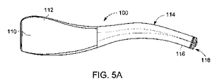
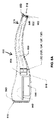
本開示の一態様によれば、腫瘍/癌細胞の視覚化のための手持ち式の白色光および蛍光ベースの撮像デバイスが提供される。白色光および蛍光ベースの撮像デバイスは、使用者の片手で保持および操作されるようなサイズおよび形状の本体を含むことができる。手持ち式の白色光および蛍光ベースの撮像デバイスの例示的な実施形態が、図5A〜図5Cに示されている。図示のように、いくつかの例示的な実施形態では、本体は、略細長形状を有することができ、切除腫瘍の外面上、切除腫瘍の1つもしくは複数の区間上、腫瘍/組織が切除された手術腔内、または露出された手術層上に、使用者の手の中に保持されるように構成された第1の端部および外科的マージン上へ光を誘導するように構成された第2の端部を含むことができる。第2の端部は、外科的マージンを含む手術腔内に位置決めされるようにさらに構成することができる。デバイスの本体は、滅菌に好適な1つまたは複数の材料を含むことができ、したがってデバイスの本体は、例えばオートクレーブ内などで、滅菌を受けることができる。好適な材料の例には、ポリプロピレン、ポリスルホン、ポリエーテルイミド、ポリフェニルスルホン、エチレンクロロトリフルオロエチレン、エチレンテトラフルオロエチレン、フッ素化エチレンプロピレン、ポリクロロトリフルオロエチレン、ポリエーテルエーテルケトン、ペルフルオロアルコキシ、ポリスルホン、ポリフェニルスルホン、およびポリエーテルイミドが含まれる。他の好適な材料も、当業者にはよく知られているであろう。オートクレーブ、例えば電子機器などの条件に耐えることが可能でないデバイスの本体内の構成要素は、保護用のハウジング、例えば金属またはセラミックのハウジング内に、固定または他の方法で収容することができる。 According to one aspect of the present disclosure, a handheld white light and fluorescence based imaging device for visualization of tumor / cancer cells is provided. White light and fluorescence based imaging devices can include bodies of a size and shape that can be held and manipulated with one hand of the user. Illustrative embodiments of handheld white light and fluorescence based imaging devices are shown in FIGS. 5A-5C. As shown, in some exemplary embodiments, the body can have a substantially elongated shape and the tumor / tissue is resected on the outer surface of the resected tumor, on one or more sections of the resected tumor. A second configured to direct light into a surgical cavity or on an exposed surgical layer onto a first end and surgical margin configured to be held in the user's hand. It can include two ends. The second end can be further configured to be positioned within the surgical cavity including the surgical margin. The body of the device can contain one or more materials suitable for sterilization, so the body of the device can be sterilized, for example in an autoclave. Examples of suitable materials include polypropylene, polysulfone, polyetherimide, polyphenylsulfone, ethylenechlorotrifluoroethylene, ethylenetetrafluoroethylene, fluorinated ethylenepropylene, polychlorotrifluoroethylene, polyetheretherketone, perfluoroalkoxy, Includes polysulfone, polyphenylsulfone, and polyetherimide. Other suitable materials will also be well known to those of skill in the art. Components within the body of a device that cannot withstand conditions such as an autoclave, such as an electronic device, can be fixed or otherwise housed in a protective housing, such as a metal or ceramic housing.
デバイスは、外科用ドレープまたはシールドとともに使用されるように構成することができる。例えば、本発明者らは、撮像区域内で周囲および人工光が低減されたとき、画像品質が改善されることを見出した。これは、使用中の周囲および/または人工光源を削減または除去することによって実現することができる。別法として、ドレープまたはシールドを使用して、撮像が行われている手術部位から周囲および/または人工光の少なくとも一部分を阻止することができる。1つの例示的な実施形態では、シールドは、デバイスの第2の端部の上に嵌り、デバイス上を手術腔の方へかつ手術腔から離れる方へ動いて、手術腔に入りうる周囲および/または人工光の量を変動させるように構成することができる。シールドは、円錐または傘形状とすることができる。別法として、手術部位を白色光および励起光で照射するように構成されたデバイスの端部を覆う透明のシース部分によって、デバイス自体をドレープ内に密閉することができる。 The device can be configured for use with a surgical drape or shield. For example, we have found that image quality is improved when ambient and artificial light are reduced within the imaging area. This can be achieved by reducing or eliminating the ambient and / or artificial light sources in use. Alternatively, a drape or shield can be used to block at least a portion of the ambient and / or artificial light from the surgical site where the imaging is taking place. In one exemplary embodiment, the shield fits over the second end of the device and moves over the device towards and away from the surgical cavity around it and / /. Alternatively, it can be configured to vary the amount of artificial light. The shield can be conical or umbrella shaped. Alternatively, the device itself can be sealed within the drape by a transparent sheath portion covering the end of the device configured to illuminate the surgical site with white and excitation light.
いくつかの実施形態では、デバイスは、デバイスの滅菌状態を支持するように、ドレープの取付けを容易にするための提供を含むことができる。例えば、ドレープは、ドレープ内に収容された滅菌されていないデバイスと滅菌された手術領域との間に滅菌された障壁を提供し、それによって滅菌されたドレープ内に完全に収容された滅菌されていないデバイスを、滅菌された環境で使用することを可能にすることができる。ドレープは、デバイスを覆うことができ、デバイスの遠位端から延びて手術腔に隣接する区域を覆い、デバイス以外の光源からの光の侵入から手術腔区域を保護する減光シールドを提供することもできる。 In some embodiments, the device can include a provision to facilitate the attachment of the drape to support the sterile condition of the device. For example, the drape provides a sterile barrier between the non-sterile device contained within the drape and the sterile surgical area, thereby being completely sterile contained within the sterile drape. No device can be made available for use in a sterile environment. The drape can cover the device, extending from the distal end of the device to cover the area adjacent to the surgical cavity and providing a dimming shield that protects the surgical cavity area from the ingress of light from non-device light sources. You can also.
ドレープまたはシールドは、ポリマー材料、例えばポリエチレン、ポリウレタン、または他のポリマー材料などを含むことができる。いくつかの実施形態では、ドレープまたはシールドは、保持デバイスによってデバイスに結合することができる。例えば、デバイスは、ドレープまたはシールドをデバイス上で保持するために、ドレープまたはシールド上の1つまたは複数の特徴と相互作用するように構成された1つまたは複数の溝を含むことができる。追加または別法として、ドレープまたはシールドは、ドレープまたはシールドをデバイス上で保持するために、保持リングまたはバンドを含むことができる。保持リングまたはバンドは、弾性バンド、スナップリング、または類似の構成要素を含むことができる。いくつかの実施形態では、ドレープまたはシールドは、1回だけの使用に好適なものとすることができる。 The drape or shield can include polymeric materials such as polyethylene, polyurethane, or other polymeric materials. In some embodiments, the drape or shield can be attached to the device by a holding device. For example, the device can include one or more grooves configured to interact with one or more features on the drape or shield to hold the drape or shield on the device. In addition or otherwise, the drape or shield may include a retaining ring or band to hold the drape or shield on the device. The retaining ring or band can include elastic bands, snap rings, or similar components. In some embodiments, the drape or shield can be suitable for one-time use.
ドレープまたはシールドはまた、デバイスから放射された光の正確な伝送を確保するために、デバイスの遠位端を覆う堅い光学窓を含むことができ、またはそのような光学窓に結合することができる。窓は、材料、例えばポリメチルメタクリレート(PMMA)または他の剛性の光透過性ポリマー、ガラス、シリコーン、石英、または他の材料などを含むことができる。 The drape or shield can also include a rigid optical window covering the distal end of the device, or be coupled to such an optical window, to ensure accurate transmission of light emitted from the device. .. The window can include a material such as polymethylmethacrylate (PMMA) or other rigid light-transmitting polymer, glass, silicone, quartz, or other material.
ドレープまたはシールドは、デバイスの励起光に影響を与えたり変更したりしない。ドレープまたはシールドの窓は、405nmまたはIR/NIR励起下では自家蛍光しない。追加として、ドレープまたはシールドの材料は、デバイスとの間の無線信号伝達に干渉しない。 The drape or shield does not affect or alter the excitation light of the device. Drape or shield windows do not autofluorescent under 405 nm or IR / NIR excitation. In addition, the drape or shield material does not interfere with the radio signal transmission to and from the device.
当業者には理解されるように、周囲および/または人工光を低減または除去するように構成されたドレープまたはシールドの他の変形形態を使用することもできる。 Other variants of the drape or shield configured to reduce or eliminate ambient and / or artificial light may also be used, as will be appreciated by those skilled in the art.
追加または別法として、手持ち式の白色光および蛍光ベースの撮像デバイスは、照明状態が撮像にとって満足であるかどうかを識別するように構成されたセンサを含むことができる。例えば、蛍光撮像は十分に暗い環境でのみ有効になることができるため、デバイスは、周囲照明状態が蛍光撮像を可能にするのに十分であることを示すように構成された周囲光センサを含むことができる。周囲光センサは、周囲光レベルに関するフィードバックを臨床医へ提供することができる。追加として、システムが蛍光撮像モードになる前の周囲光レベルを、ピクチャメタデータ内に記憶することができる。光レベルは、事後分析中に有用になる可能性がある。周囲光センサはまた、白色光撮像モード中に、白色光LEDのイネーブルまたはその強度の制御のために有用になる可能性がある。 In addition or otherwise, handheld white light and fluorescence based imaging devices can include sensors configured to identify whether the illumination conditions are satisfactory for imaging. For example, since fluorescence imaging can only be enabled in a sufficiently dark environment, the device includes an ambient light sensor configured to indicate that the ambient lighting conditions are sufficient to enable fluorescence imaging. be able to. The ambient light sensor can provide feedback to the clinician regarding the ambient light level. In addition, the ambient light level before the system goes into fluorescence imaging mode can be stored in the picture metadata. Light levels can be useful during post hoc analysis. Ambient light sensors can also be useful for enabling or controlling the intensity of white light LEDs during white light imaging modes.
デバイスは、外科的マージン、手術層、または切除組織標本の組織細胞の自家蛍光放射および組織細胞内の誘起ポルフィリンの蛍光放射を励起するように構成された少なくとも1つの励起光源をさらに含むことができ、これはデバイスの本体内に収容される。本明細書では、組織が切除された後、切除組織標本を検査するために、外科的マージンおよび/または手術層を検査する目的で、デバイスの使用について論じるが、デバイスは、原発腫瘍の切除中に、例えば腫瘍と非癌組織とを区別するための案内として使用することができることが、本発明者らには企図され、本出願の範囲内である。追加または別法として、本出願のデバイスはまた、衛星病変および/または腫瘍の除去を案内するために使用することもできる。したがって、デバイスはまた、外科的処置中に実時間調整を行うために使用することができる。 The device can further include at least one excitation source configured to excite the autofluorescent radiation of the tissue cells of the surgical margin, surgical layer, or excised tissue specimen and the fluorescence radiation of induced porphyrins within the tissue cells. , It is housed inside the body of the device. The present specification discusses the use of the device for the purpose of examining the surgical margin and / or the surgical layer to examine the resected tissue specimen after the tissue has been resected, although the device is being resected of the primary tumor. In addition, it is intended by the present inventors that it can be used as a guide for distinguishing between tumors and non-cancerous tissues, for example, and is within the scope of this application. In addition or otherwise, the devices of this application can also be used to guide the removal of satellite lesions and / or tumors. Therefore, the device can also be used to make real-time adjustments during a surgical procedure.
図5A〜図5Cに示すように、少なくとも1つの励起光源は、デバイスの一端の上、周り、および/または近傍に位置決めすることができる。各光源は、例えば、選択された波長で光を放射するように構成された1つまたは複数のLEDを含むことができる。いくつかの例示的な実施形態では、デバイスが複数の方向に光を放射するように、同じ波長で光を放射するように構成されたLEDを位置決めすることができる。これにより、手術腔内により良好でより一貫した照射が提供される。 As shown in FIGS. 5A-5C, at least one excitation light source can be positioned above, around, and / or near one end of the device. Each light source can include, for example, one or more LEDs configured to emit light at a selected wavelength. In some exemplary embodiments, LEDs configured to emit light at the same wavelength can be positioned such that the device emits light in multiple directions. This provides better and more consistent irradiation within the surgical cavity.
励起光源は、組織の自家蛍光放射、他の生体成分、例えば流体などの自家蛍光、ならびに切除腫瘍/組織の外科的マージン内および/または腫瘍/組織細胞が切除された手術層の外科的マージン内に含まれる腫瘍/癌細胞内の誘起ポルフィリンの蛍光放射を励起するように選択された単一の波長の励起光を提供することができる。一例では、励起光は、約350nm〜約600nm、もしくは約350nm〜約450nm、および約550nm〜約600nm、または例えば405nmもしくは例えば572nmの範囲内の波長を有することができる。図2Aおよび図2Bを参照されたい。励起光源は、約350nm〜約400nm、約400nm〜約450nm、約450nm〜約500nm、約500nm〜約550nm、約550nm〜約600nm、約600nm〜約650nm、約650nm〜約700nm、約700nm〜約750nm、約750nm〜約800nm、約800nm〜約850nm、約850nm〜約900nm、および/またはこれらの組合せの波長を有する励起光を放射するように構成することができる。 Excitation sources include autofluorescent radiation of tissue, autofluorescence of other biological components such as fluids, and within the surgical margin of the resected tumor / tissue and / or within the surgical margin of the surgical layer from which the tumor / tissue cells have been resected. It is possible to provide excitation light of a single wavelength selected to excite the fluorescent radiation of induced porphyrin in tumor / cancer cells contained in. In one example, the excitation light can have wavelengths in the range of about 350 nm to about 600 nm, or about 350 nm to about 450 nm, and about 550 nm to about 600 nm, or, for example, 405 nm or, for example, 572 nm. See FIGS. 2A and 2B. Excitation light sources are about 350 nm to about 400 nm, about 400 nm to about 450 nm, about 450 nm to about 500 nm, about 500 nm to about 550 nm, about 550 nm to about 600 nm, about 600 nm to about 650 nm, about 650 nm to about 700 nm, about 700 nm to about. It can be configured to emit excitation light having wavelengths of 750 nm, about 750 nm to about 800 nm, about 800 nm to about 850 nm, about 850 nm to about 900 nm, and / or combinations thereof.
励起光源は、2つ以上の波長の励起光を提供するように構成することができる。励起光の波長は、当業者には理解されるように、異なる目的で選択することができる。例えば、励起光の波長を変動させることによって、励起光が手術層を侵入する深さを変動させることが可能である。侵入深さは、波長の対応する増大とともに増大するため、異なる波長の光を使用して、手術層/外科的マージンの表面下の組織を励起することが可能である。一例では、350nm〜450nmの範囲内、例えば約405nm±10nmの波長を有する励起光、および550nm〜600nmの範囲内、例えば約572nm±10nmの波長を有する励起光が、手術層/外科的マージンを形成する組織に異なる深さまで、例えばそれぞれ約500μm〜約1mmおよび約2.5mmまで侵入することができる。これにより、デバイスの使用者、例えば外科医または病理学者が、手術層/外科的マージンの表面および手術層/外科的マージンの表面下の腫瘍/癌細胞を視覚化することが可能になる。図3Aおよび図3Bを参照されたい。励起光源はそれぞれ、約350nm〜約400nm、約400nm〜約450nm、約450nm〜約500nm、約500nm〜約550nm、約550nm〜約600nm、約600nm〜約650nm、約650nm〜約700nm、約700nm〜約750nm、約750nm〜約800nm、約800nm〜約850nm、約850nm〜約900nm、および/またはこれらの組合せの波長を有する励起光を放射するように構成することができる。 The excitation light source can be configured to provide excitation light of two or more wavelengths. The wavelength of the excitation light can be selected for different purposes, as will be appreciated by those skilled in the art. For example, by varying the wavelength of the excitation light, it is possible to vary the depth at which the excitation light penetrates the surgical layer. Since the penetration depth increases with the corresponding increase in wavelength, it is possible to use light of different wavelengths to excite the tissue beneath the surface of the surgical layer / surgical margin. In one example, excitation light in the range of 350 nm to 450 nm, eg, a wavelength of about 405 nm ± 10 nm, and excitation light, in the range of 550 nm to 600 nm, eg, a wavelength of about 572 nm ± 10 nm, provide a surgical layer / surgical margin. It can penetrate the tissue to be formed to different depths, for example from about 500 μm to about 1 mm and about 2.5 mm, respectively. This allows the user of the device, eg, a surgeon or pathologist, to visualize tumors / cancer cells on the surface of the surgical layer / surgical margin and under the surface of the surgical layer / surgical margin. See FIGS. 3A and 3B. The excitation light sources are about 350 nm to about 400 nm, about 400 nm to about 450 nm, about 450 nm to about 500 nm, about 500 nm to about 550 nm, about 550 nm to about 600 nm, about 600 nm to about 650 nm, about 650 nm to about 700 nm, and about 700 nm, respectively. It can be configured to emit excitation light having wavelengths of about 750 nm, about 750 nm to about 800 nm, about 800 nm to about 850 nm, about 850 nm to about 900 nm, and / or combinations thereof.
追加または別法として、近赤外/赤外範囲内の波長を有する励起光を使用することができ、例えば約760nm〜約800nm、例えば約760nm±10nmまたは約780nm±10nmの波長を有する励起光を使用することができる。追加として、より深いレベルまで組織に侵入するために、このタイプの光源の使用は、第2のタイプの撮像/造影剤、例えば赤外(IR)染料(例えば、IRdye800、インドシアニングリーン(ICG))などとともに使用することができる。図4Aおよび図4Bを参照されたい。これにより、例えば外科的マージン/手術層内の血管新生、血管灌流、および血管貯留の視覚化が可能になり、外科医は、残存腫瘍/癌細胞が手術層内に残っている可能性に関する判定を行う際に、この情報を使用することができる。追加として、再建中の吻合を改善するために血管灌流を視覚化する有用性も有益になるはずである。 As an additional or alternative, excitation light with wavelengths in the near-infrared / infrared range can be used, eg, excitation light with wavelengths from about 760 nm to about 800 nm, such as about 760 nm ± 10 nm or about 780 nm ± 10 nm. Can be used. In addition, to penetrate deeper levels of tissue, the use of this type of light source is a second type of imaging / contrast agent, such as an infrared (IR) dye (eg, IRdie800, indocyanine green (ICG)). ) Etc. can be used together. See FIGS. 4A and 4B. This allows, for example, visualization of angiogenesis, vascular perfusion, and vascular retention within the surgical margin / surgical layer, allowing the surgeon to determine the likelihood of residual tumor / cancer cells remaining within the surgical layer. You can use this information when doing so. In addition, the usefulness of visualizing vascular perfusion to improve anastomosis during reconstruction should also be beneficial.
したがって、励起光は、誘起ポルフィリンを含む標的組織を蛍光させる励起光を放射するように構成された1つまたは複数の光源を構成することができ、デバイスの使用者、例えば外科医などは、その蛍光の色によって標的組織(例えば、腫瘍、癌細胞、衛星病変など)を識別することが可能になる。追加の組織成分が、励起光による照射に応答して蛍光することもできる。少なくともいくつかの例では、追加の組織成分は、誘起ポルフィリンを含む標的組織とは異なる色で蛍光し、デバイスの使用者(例えば、外科医)は、標的組織と他の組織とを区別することが可能になる。例えば、励起光が約405nmの波長を有する光を放射したとき、誘起ポルフィリンを含む標的組織は、明赤色で蛍光する。標的組織を取り囲みかつ/または標的組織に隣接する同じ手術部位、マージン、手術層、または切除標本内の結合組織(例えば、コラーゲン、エラスチンなど)は、同じ励起光によって照射されたとき、緑色で蛍光する。さらに、標的組織および/もしくは結合組織を取り囲みかつ/または標的組織および/もしくは結合組織に隣接する同じ手術部位、マージン、手術層、または切除標本内の脂肪組織は、同じ励起光によって照射されたとき、ピンク色がかった茶色で蛍光する。他の波長の励起光を追加することで、手術部位、マージン、手術層、または切除標本に関するさらなる情報を使用者(例えば、外科医)に提供することができる。例えば、約572nmの励起光を放射するように構成された励起光源を追加することで、上記の組織を同じ色であるが、手術部位、外科的マージン、手術層、または切除標本の表面下の深さで見せる。別法または追加として、別の励起光、約760nmの励起光を放射するように構成された励起光を追加することで、使用者(例えば、外科医)は、手術部位、外科的マージン、手術層、または外科的標本内で血管新生の区域を識別することが可能になる。NIR染料(例えば、IRdye800またはICG)の使用により、血管新生は、NIR染料を含まない周辺組織とは対照的に、近赤外(NIR)波長帯域で蛍光して見える。例えば、血管新生は、暗黒色の背景とは対照的に、明白色、灰色、または紫色に見えることができる。デバイスは、追加の光源、例えば外科的マージン/手術層/組織標本/乳腺腫瘤摘出サンプルの白色光(WL)撮像のための白色光源などを含むことができる。少なくともいくつかの事例では、例えばBCS、例えば乳腺腫瘤摘出術中など、腫瘍の除去により、手術層/外科的マージンを含む手術腔が生じる。WL撮像は、手術腔および/または外科的マージンの内部の画像またはビデオを取得し、手術腔の視覚化を提供するために使用することができる。WL撮像はまた、手術層または切除組織サンプルの画像またはビデオを取得するために使用することができる。WL画像および/またはビデオは、使用者(例えば、外科医)に対して細胞学的および地形学的な基準点を提供する。WL撮像下で、手術層または切除組織は、有用な情報を使用者(例えば、外科医および/または病理学者)に提供する。例えば、WL画像は、組織のうち、黄色に見える脂肪(脂質)組織、典型的には白色に見える結合組織、ならびに明赤色または暗赤色に見える血液区域を含む区域を示すことができる。追加として、WL画像内では、湿気、焼灼からの炭化、発色性染料による染色、術中または他の外因的目的(例えば、マージンのマーク付け、ワイアガイドの配置)を視覚化することができる。さらに、WL画像は、対応するFL画像を解釈するための状況を提供することができる。例えば、FL画像は、「細胞学的状況」(すなわち、背景組織の自家蛍光)を提供することができ、対応するWL画像は、何がFL画像(例えば、切除標本ではなく手術腔の画像)に示されているかを使用者がより良好に理解することを可能にすることができる。WL画像もまた、使用者がFL画像内の蛍光特徴を白色光照射下の細胞学的位置に共局在化することを可能にする。 Thus, the excitation light can constitute one or more light sources configured to emit excitation light that fluoresces the target tissue containing induced porphyrin, and the device user, such as a surgeon, may see the fluorescence. The color of the light makes it possible to identify target tissues (eg, tumors, cancer cells, satellite lesions, etc.). Additional tissue components can also fluoresce in response to irradiation with excitation light. In at least some examples, additional tissue components fluoresce in a different color than the target tissue containing the induced porphyrin, allowing the user of the device (eg, a surgeon) to distinguish the target tissue from other tissues. It will be possible. For example, when the excitation light emits light having a wavelength of about 405 nm, the target tissue containing the induced porphyrin fluoresces in bright red. Connective tissue (eg, collagen, elastin, etc.) within the same surgical site, margin, surgical layer, or resected specimen that surrounds and / or is adjacent to the target tissue fluoresces green when illuminated by the same excitation light. To do. In addition, when the adipose tissue in the same surgical site, margin, surgical layer, or excised specimen that surrounds and / or is adjacent to the target tissue and / or connective tissue is irradiated with the same excitation light. , Pinkish brown and fluorescent. By adding excitation light of other wavelengths, additional information about the surgical site, margin, surgical layer, or excised specimen can be provided to the user (eg, the surgeon). For example, by adding an excitation light source configured to emit excitation light of about 572 nm, the above tissue is of the same color, but under the surface of the surgical site, surgical margin, surgical layer, or excised specimen. Show in depth. Alternatively or additionally, by adding another excitation light, an excitation light configured to emit an excitation light of about 760 nm, the user (eg, a surgeon) can use the surgical site, surgical margin, surgical layer. , Or it becomes possible to identify areas of angiogenesis within the surgical specimen. With the use of NIR dyes (eg, IRdie800 or ICG), angiogenesis appears to fluoresce in the near infrared (NIR) wavelength band, as opposed to peripheral tissues that do not contain NIR dyes. For example, angiogenesis can appear as a clear color, gray, or purple, as opposed to a dark black background. The device can include additional light sources such as a white light source for white light (WL) imaging of surgical margins / surgical layers / tissue specimens / breast mass excision samples. In at least some cases, removal of the tumor, for example during BCS, eg, during mastectomy, results in a surgical cavity that includes a surgical layer / surgical margin. WL imaging can be used to capture images or videos of the interior of the surgical cavity and / or surgical margin and provide visualization of the surgical cavity. WL imaging can also be used to obtain images or videos of surgical layers or excised tissue samples. WL images and / or videos provide the user (eg, surgeon) with cytological and geomorphological reference points. Under WL imaging, the surgical layer or excised tissue provides useful information to the user (eg, surgeon and / or pathologist). For example, a WL image can show areas of tissue that include fat (lipid) tissue that appears yellow, connective tissue that typically appears white, and blood areas that appear bright red or dark red. In addition, within the WL image, moisture, carbonization from cauterization, staining with chromogenic dyes, intraoperative or other extrinsic purposes (eg, margin marking, wire guide placement) can be visualized. In addition, the WL image can provide a situation for interpreting the corresponding FL image. For example, an FL image can provide a "cytological situation" (ie, autofluorescence of background tissue), and a corresponding WL image is what an FL image (eg, an image of a surgical cavity rather than an excised specimen). It can allow the user to better understand what is shown in. The WL image also allows the user to co-localize the fluorescence features in the FL image to the cytological location under white light irradiation.
白色光源は、1つまたは複数の白色光LEDを含むことができる。他の白色光源も適宜使用することができる。当業者には理解されるように、白色光源は、長期使用中に過熱をもたらすことなく、安定した信頼できるものであるべきである。 The white light source can include one or more white light LEDs. Other white light sources can also be used as appropriate. As will be appreciated by those skilled in the art, the white light source should be stable and reliable without causing overheating during long-term use.
デバイスの本体は、白色光撮像と蛍光撮像との間の切換え/トグルを可能にするための制御を含むことができる。制御はまた、ともにもしくは別個に、様々な組合せで、かつ/または順次、様々な励起光源の使用を可能にすることができる。制御は、様々な異なる光源の組合せを繰り返すことができ、これらの光源を順次制御することができ、これらの光源を明滅させることができ、または他の方法で光源使用のタイミングおよび持続時間を制御することができる。制御は、当業者には理解されるように、自動、手動、またはこれらの組合せとすることができる。 The body of the device can include controls to allow switching / toggle between white light imaging and fluorescence imaging. Controls can also allow the use of different excitation sources, either together or separately, in various combinations and / or sequentially. The control can repeat a variety of different combinations of light sources, can control these light sources sequentially, can blink these light sources, or otherwise control the timing and duration of light source use. can do. Control can be automatic, manual, or a combination thereof, as will be appreciated by those skilled in the art.
デバイスの本体はまた、反射された励起光の通過を防止するが、組織細胞の自家蛍光放射および組織細胞内の誘起ポルフィリンの蛍光放射に対応する波長を有する放射の通過は許可するように構成されたスペクトルフィルタを収容することができる。1つの例示的な実施形態では、赤色蛍光放射(自家蛍光および誘起ポルフィリン放射の両方)および緑色自家蛍光放射に対応する波長を有する放射の通過を許可することができるmCherryフィルタを使用することができ、赤色帯域は、脂肪組織の自家蛍光放射およびPpIX放射を捕捉し、緑色帯域は、結合組織の自家蛍光放射を捕捉する。図2A〜図2Bおよび図3A〜図3Bに示すように、緑色帯域は、約500nm〜約550nmの波長を有する放射の通過を許可することができ、赤色帯域は、約600nm〜660nmの波長を有する放射の通過を許可することができる(赤色帯域は約600nm〜約725nmに延びることができることも可能である)。mCherryフィルタは、赤外励起光による励起、例えば約790nm以上の波長を有する放射に応答して、放射の通過を許可するように構成された帯域をさらに含むことができる。図4Aを参照されたい。別法として、mCherryフィルタではなく、複数のフィルタを使用することもでき、各フィルタは、1つまたは複数の帯域の放射の通過を許可するように構成される。一例では、800nmのロングパスフィルタを使用して、800nm以上の波長を有する放射を捕捉することができる。図4Bを参照されたい。追加または別法として、フィルタホイールを使用することができる。当業者には理解されるように、フィルタは、他の関心組織成分、例えば流体などの検出を可能にするように、さらにカスタマイズすることができる。 The body of the device is also configured to block the passage of reflected excitation light, but to allow the passage of radiation with wavelengths corresponding to the autofluorescent radiation of the tissue cells and the fluorescence radiation of the induced porphyrin within the tissue cells. Can accommodate a spectral filter. In one exemplary embodiment, an mCherry filter can be used that can allow the passage of radiation with wavelengths corresponding to red autofluorescence (both autofluorescence and induced porphyrin radiation) and green autofluorescence. The red band captures the autofluorescent and PpIX radiation of connective tissue, and the green band captures the autofluorescent radiation of connective tissue. As shown in FIGS. 2A-2B and 3A-3B, the green band can allow the passage of radiation having a wavelength of about 500 nm to about 550 nm, and the red band has a wavelength of about 600 nm to 660 nm. It can allow the passage of its radiation (the red band can also extend from about 600 nm to about 725 nm). The mCherry filter can further include a band configured to allow the passage of radiation in response to excitation by infrared excitation light, eg, radiation having a wavelength of about 790 nm or higher. See FIG. 4A. Alternatively, multiple filters may be used instead of the mCherry filter, each filter configured to allow the passage of radiation in one or more bands. In one example, an 800 nm long pass filter can be used to capture radiation with wavelengths above 800 nm. See FIG. 4B. An additional or alternative filter wheel can be used. As will be appreciated by those skilled in the art, the filter can be further customized to allow detection of other tissue components of interest, such as fluids.
手持ち式の白色光および蛍光ベースの撮像デバイスはまた、撮像レンズおよび画像センサを含む。撮像レンズまたはレンズアセンブリは、フィルタにかけられた自家蛍光放射および蛍光放射を画像センサ上に集束させるように構成することができる。広角撮像レンズまたは魚眼撮像レンズが、好適なレンズの例である。広角レンズは、180度の視野を提供することができる。レンズはまた、光学倍率を提供することができる。撮像デバイスには、非常に小さい細胞群を区別することが可能になるように、非常に高い分解能(例えば、マイクロメートルレベル)が望ましい。これは、手術中に保持される健康な組織の量を最大にしながら、実質上すべての残存癌細胞、前癌細胞、衛星病変を除去する可能性を最大にするという目標を実現するために望ましい。画像センサは、外科的マージンのフィルタにかけられた組織細胞の自家蛍光放射および組織細胞内の誘起ポルフィリンの蛍光放射を検出するように構成され、画像センサは、ポルフィリン蛍光および組織の自家蛍光のスペクトル色を正確に表すように調整することができる。画像センサは、4Kビデオ能力ならびに自動焦点および光学ズーム能力を有することができる。CCDまたはCMOS撮像センサを使用することができる。一例では、フィルタと組み合わせたCMOSセンサ、すなわちハイパースペクトル画像センサ、例えばXimea社から販売されているセンサなどを使用することができる。例示的なフィルタには、可視光フィルタ(https://www.ximea.com/en/products/hyperspectral−cameras−based−on−usb3−xispec/mq022hg−im−sm4x4−vis)およびIRフィルタ(https://www.ximea.com/en/products/hyperspectral−cameras−based−on−usb3−xispec/mq022hg−im−sm5x5−nir)が含まれる。手持ち式デバイスはまた、検出された放射を受け取り、外科的マージンのフィルタにかけられて検出された組織細胞の自家蛍光放射および組織細胞内の誘起ポルフィリンの蛍光放射に関するデータを出力するように構成されたプロセッサを収容することができる。プロセッサは、同時プログラムを継ぎ目なく実行する能力を有することができる(それだけに限定されるものではないが、無線信号の監視、電池の監視および制御、温度の監視、画像の受入れ/圧縮、ならびにボタン押下の監視を含む)。プロセッサは、内部記憶装置、ボタン、光学系、および無線モジュールとインターフェースする。プロセッサはまた、アナログ信号を読み取る能力を有する。 Handheld white light and fluorescence based imaging devices also include imaging lenses and imaging sensors. The imaging lens or lens assembly can be configured to focus the filtered autofluorescent radiation and the fluorescent radiation onto the image sensor. A wide-angle imaging lens or a fisheye imaging lens is an example of a suitable lens. A wide-angle lens can provide a 180 degree field of view. The lens can also provide optical magnification. Very high resolution (eg, micrometer level) is desirable for the imaging device so that it is possible to distinguish very small cell populations. This is desirable to achieve the goal of maximizing the likelihood of removing virtually all residual cancer cells, precancerous cells, and satellite lesions while maximizing the amount of healthy tissue retained during surgery. .. The image sensor is configured to detect the autofluorescence of surgical margin filtered tissue cells and the induced porphyrin fluorescence in the tissue cells, and the image sensor is a spectral color of porphyrin fluorescence and tissue autofluorescence. Can be adjusted to accurately represent. The image sensor can have 4K video capability as well as autofocus and optical zoom capability. A CCD or CMOS imaging sensor can be used. In one example, a CMOS sensor combined with a filter, i.e. a hyperspectral image sensor, such as a sensor sold by Ximea, can be used. Illustrative filters include visible light filters (https://www.ximea.com/en/products/hyperspectral-cameras-based-on-usb3-xispec/mq022hg-im-sm4x4-vis) and IR filters (https). : //Www.ximea.com/en/products/hyperspectral-cameras-based-on-usb3-xispec/mq022hg-im-sm5x5-nir). The handheld device was also configured to receive the detected radiation and output data on the autofluorescence of the detected tissue cells filtered by the surgical margin and the fluorescence of the induced porphyrin in the tissue cells. Can accommodate a processor. Processors can have the ability to seamlessly execute simultaneous programs (but not limited to, radio signal monitoring, battery monitoring and control, temperature monitoring, image acceptance / compression, and button presses. Including monitoring of). The processor interfaces with internal storage, buttons, optics, and wireless modules. The processor also has the ability to read analog signals.
デバイスはまた、無線モジュールを含むことができ、完全に無線で動作するように構成することができる。デバイスは、ハイスループット無線信号を利用することができ、最小の待ち時間で高精細度ビデオを伝送する能力を有することができる。デバイスは、Wi−FiおよびBluetoothの両方に対応することができ、Wi−Fiはデータ伝送のために、Bluetoothは高速接続のために使用される。デバイスは、他のデバイスからの分離のために、5GHzの無線伝送帯域の動作を利用することができる。さらに、デバイスは、ソフトアクセスポイントとして実行することが可能であり、それによりインターネットへの接続の必要をなくし、患者データのセキュリティに関連する他のデバイスから分離して接続された状態でデバイスおよびモジュールを維持する。 The device can also include a wireless module and can be configured to operate completely wirelessly. The device can utilize high-throughput radio signals and can have the ability to transmit high-definition video with minimal latency. The device can support both Wi-Fi and Bluetooth, Wi-Fi is used for data transmission and Bluetooth is used for high speed connectivity. The device can utilize the operation of the radio transmission band of 5 GHz for isolation from other devices. In addition, the device can run as a soft access point, eliminating the need for an internet connection and leaving the device and module connected separately from other devices related to patient data security. To maintain.
デバイスは、無線で充電するように構成することができ、誘導充電コイルを含むことができる。追加または別法として、デバイスは、充電接続を受け取るように構成されたポートを含むことができる。 The device can be configured to charge wirelessly and can include an inductive charging coil. In addition or otherwise, the device can include a port configured to receive a charging connection.
本開示の一態様によれば、本教示による手持ち式の多スペクトル撮像デバイス100の例示的な実施形態が、図5A〜図5Cに示されている。デバイス100は、第1の端部112および第2の端部114を有する本体110含む。第1の端部112は、デバイスの使用者によって片手で保持されるようなサイズおよび形状である。図示されていないが、第2の端部が関節動作可能な構造として実施されるとき、第1の端部は、デバイスの作動、異なる光源間のトグルおよび/または他の方法による異なる光源の制御、ならびに第2の端部114の操作を行うように構成された制御を含むことができる。
According to one aspect of the present disclosure, exemplary embodiments of the handheld
図5A〜図5Cに示すように、デバイス100の第2の端部114は、腫瘍または癌組織が除去された手術腔内へ、2〜3cmのサイズの外科的切開を通って第2の端部の端部または先端116の挿入を容易にするために、先細り状および/または細長形にすることができる。端部または先端116は、端部の周囲もしくは円周および/またはデバイス100の端面118に、光源を含む。端面118は、例えば、広角レンズ162を含む。1つの例示的な実施形態では、白色光LED122を備える第1の白色光源120が、デバイスの先端116および端面118上に位置決めされる。例えばLED126の形態の405nmの励起光源を備える第2の光源124がまた、デバイス100の先端116および端面118上に位置決めされる。いくつかの実施形態では、LED122および126は、交互のパターンで配置することができる。図5Dに示す別の例示的な実施形態では、例えばLED130の形態の575nmの励起光源を備える第3の光源128がまた、先端116および端面118上に位置決めされる。図5Eに示すさらに別の代替実施形態では、760nmの励起光を放射するように構成されたLED134を備える赤外光源132の形態の第4の光源が、デバイス100の先端116および端面118上に位置決めされる。当業者には理解されるように、これらの様々な光源は、様々な組合せで設けることができ、すべての光源を設ける必要はない。1つの例示的な実施形態では、デバイスの先端部116は取外し可能であり、他の先端と交換可能になるように構成される。そのような実施形態では、図5C〜図5Eに示す先端は、単一のデバイス上で交換可能な異なる先端を構成することができる。他の組合せの光源およびフィルタを備える追加の先端も、本開示によって企図される。例示的な先端は、405nmの光およびmCherryフィルタ、フィルタなしの白色光、IR/NIR光および800nmロングパスフィルタ、IR/NIR光およびmCherryフィルタ、405nmの光、IR/NIR光、およびmCherryフィルタ、572nmの光およびmCherryフィルタ、405nmの光、572nmの光、およびmCherryフィルタ、405nmの光、572nmの光、IR/NIR光、およびmCherryフィルタ、ならびに572nmの光、IR/NIR光、およびmCherryフィルタという組合せの光源およびフィルタを含むことができる。交換可能な先端の使用により、フィルタ間でトグルしなければならないという設計上の課題が解消される。当業者には理解されるように、本開示に基づいて、他の組合せを形成することもできる。
As shown in FIGS. 5A-5C, the
先端116が取外し可能および交換可能であるデバイス100の実施形態では、交換用先端を収容するキットを販売することもできることが考えられる。そのようなキットは、デバイス自体と組み合わせて提供することができ、またはキット内に収容された先端上に含まれるタイプの光源とともに使用される1つもしくは複数の化合物もしくは染料を含むことができる。例えば、405nmの光源先端を有するキットは、ALAを含む可能性があり、405nmの光源および760nmの光源先端を有するキットは、ALAならびにIRdye800および/またはICGの両方を含む可能性がある。他の組合せの光源および化合物も、当業者には明らかであろう。
In an embodiment of the
図6Aおよび図6Bは、図5A〜図5Cの実施形態のデバイスならびにデバイス600の先端616および端面618の横断面図を示す。端面618は、例えば、広角レンズ662を含む。図6Aに示すように、デバイス600は、デバイス本体またはハウジング610を含み、本体610は、誘導充電コイル640と、電子機器基板642と、様々な光源および電子機器基板に給電するための電池644と、カメラモジュール/画像センサ648ならびにデバイスの本体に取り付けられた先端内に存在することができる光源120、124、128、および132のいずれかに電子機器基板642を接続するための電気的接続646とを収容する。光源は、光学的に透明の窓650によって覆われる。光源には、ヒートシンク654も設けられる。カメラモジュール/画像センサ648の前に、スペクトルフィルタ/撮像フィルタ652が位置決めされる。フィルタ652は、機械的にまたは手動で可動とすることができる。
6A and 6B show cross-sectional views of the devices of the embodiments of FIGS. 5A-5C and the
いくつかの実施形態では、デバイスは、偏光フィルタを含むことができる。偏光特徴は、スペクトルフィルタの一部またはスペクトルフィルタ内へ組み込まれた分離フィルタとすることができる。スペクトルフィルタ/撮像フィルタは、偏光フィルタ、例えば波長板と組み合わせた直線または円偏光フィルタとすることができる。これにより、最小の鏡面反射による組織の撮像(例えば、白色光撮像からのグレア)を防止することができ、ならびに結合組織(例えば、コラーゲンおよびエラスチン)内の蛍光偏光および/または異方性に依存する変化の撮像を可能にすることができる。追加として、偏光フィルタは、使用者が、異なる蛍光色間のコントラストをより良好に視覚化し、したがって異なる組織成分(例えば、結合と脂肪と腫瘍)間の境界をより良好に視覚化することを可能にすることができる。言い換えれば、偏光フィルタは、FL撮像下におけるより良好な境界の画定のために使用することができる。偏光フィルタはまた、WLおよびFL画像に対して組織成分間の画像コントラストを改善することができる。 In some embodiments, the device can include a polarizing filter. The polarization feature can be a part of the spectral filter or a separation filter incorporated within the spectral filter. The spectrum filter / imaging filter can be a polarizing filter, for example, a linear or circular polarizing filter combined with a wave plate. This prevents imaging of the tissue with minimal specular reflection (eg, glare from white light imaging) and depends on fluorescence polarization and / or anisotropy within the connective tissue (eg collagen and elastin). It is possible to image the changes that occur. In addition, polarizing filters allow the user to better visualize the contrast between different fluorescent colors and thus the boundaries between different tissue components (eg, binding and fat and tumor). Can be. In other words, the polarizing filter can be used for better demarcation under FL imaging. Polarizing filters can also improve the image contrast between tissue components for WL and FL images.
図7Aおよび図7Bは、デバイスの第2の代替実施形態の本体、ならびにその先端部、デバイス700、および端面718の横断面図を示す。端面718は、例えば、図7Aに示す広角レンズ762を含み、デバイス700は、デバイス本体またはハウジング710を含み、本体710は、誘導充電コイル740または充電ポート(図示せず)と、電子機器基板742と、様々な光源に供電するための電池744と、カメラモジュール/画像センサ748ならびにデバイスの本体に取り付けられた先端内に存在することができる光源120、124、128、および132のいずれかに電子機器基板742を接続するための電気的接続746とを収容する。光源は、1つまたは複数の光学的に透明の窓750によって覆われる。カメラモジュール/画像センサ748の前には、取外し可能なスペクトルフィルタ/撮像フィルタ752が位置決めされ、フィルタ752は、上述した先端116と交換可能になるように、取外し可能な先端部の一部を形成する。各先端は、別個の光源720、724、728、および732を含み、付随するフィルタ752a、752b、752c、752dが、(先端上に収容された光源に基づいて)反射された励起光の通過を防止するが、特有の先端に関連する特定の励起光波長に応答して放射の通過を許可するように構成される。追加として、本体710の先端内の各LEDに対して、ヒートシンク754が設けられる。本体710の先端は、電気接点756aをさらに含み、電気接点756aは、デバイス700の本体710上の対応する電気接点756bに接触するように構成される。いくつかの事例では、各先端上に単一の光源のみが含まれており、そのような事例では、先端はフィルタを含まなくてもよいことも企図される。
7A and 7B show a cross-sectional view of the body of a second alternative embodiment of the device, as well as its tip,
図8Aおよび図8Bは、デバイスの第3の代替実施形態の本体、ならびにその先端部、デバイス800、および端面818の横断面図を示す。図8Aに示すように、デバイス800は、デバイス本体またはハウジング810を含み、本体810は、誘導充電コイル840または充電ポート(図示せず)と、電子機器基板842と、様々な光源に給電するための電池844と、カメラモジュール/画像センサ848に電子機器基板842を接続するための電気的接続846とを収容する。光源は、ハウジング810の周囲および/またはデバイス800の先端の端部上に設けられるのではなく、デバイス800のハウジング810内に収容される。この実施形態では、各光源は、単一のLED120’、124’、128’、および/または132’を利用することができる。各光源は、ヒートシンクを伴う。追加として、光源からの光をデバイス800の端面818へ伝えるために、各光源は、それぞれのライトパイプ860を伴う。デバイスの先端は、光学的に透明の窓850、広角レンズ862、内側ライトパイプリング864a、および外側ライトパイプリング864bを含む。固体ライトパイプは、次のようにリングに接続するはずである。別のより小さいライトパイプリングが内側に同心円状に嵌るように、リングの2分の1(例えば、左半分)が固体部分に接続されるはずである。この他方のライトパイプの固体端は、例えば、内側リングの右半分に接続されるはずである。各リング全体が、光を均一に投影するが、光は本質的に、リングが均一に放射するのに十分な拡散で、リングの一部分へ送達されるはずである。この設計は、より多くの同心円状のリングを追加することによって、追加の光源のために修正することもできる(このモデルでは、各ライトパイプは、1つの源からの光のみを伝送する)。カメラモジュール/画像センサ848の前には、本体810の先端部の一部を形成するスペクトルフィルタ/撮像フィルタ852が位置決めされる。フィルタ852は、機械的にまたは手動で可動とすることができる。
8A and 8B show a cross-sectional view of the body of a third alternative embodiment of the device, as well as its tip,
図9Aおよび図9Bは、デバイスの第4の代替実施形態の本体、ならびにその先端部、デバイス900、および端面918の横断面図を示す。図9Aに示すように、デバイス900は、デバイス本体またはハウジング910を含み、本体910は、誘導充電コイル940または充電ポート(図示せず)と、電子機器基板942と、様々な光源に給電するための電池944と、カメラモジュール/画像センサ948に電子機器基板942を接続するための電気的接続946とを収容する。光源は、ハウジング910の周囲および/またはデバイス900の先端の端部上に設けられるのではなく、デバイス900のハウジング910内に収容される。この実施形態では、各光源は、複数のLED122、126、130、134を利用することができる。各光源に対するLEDは、存在するすべての光源を表すLED群を形成するように存在するそれぞれ他方の光源に対するLEDに隣接して位置決めされる。各LEDにヒートシンク954が設けられる。光源からの光をデバイス900の先端へ伝えるために、各LED群は、それぞれのライトパイプ960を伴う。デバイスの先端は、光学的に透明の窓950、広角レンズ962、ならびに各ライトパイプの遠位端、例えば端部964a、964b、964c、および964dを含む。カメラモジュール/画像センサ948の前には、本体910の先端部の一部を形成するスペクトルフィルタ/撮像フィルタ952が位置決めされる。フィルタ652は、機械的にまたは手動で可動とすることができる。
9A and 9B show a cross-sectional view of the body of a fourth alternative embodiment of the device, as well as its tip,
図10は、デバイスの第5の代替実施形態の本体、ならびにその先端部、デバイス1000、および端面1018の横断面図を示す。図10に示すように、デバイス1000は、デバイス本体またはハウジング1010を含み、本体1010は、広角レンズ1062と、誘導充電コイル1040または充電ポート(図示せず)と、電子機器基板1042と、様々な光源に給電するための電池1044と、カメラモジュール/画像センサ1048ならびにデバイスの本体に取り付けられた先端内に存在することができる光源120、124、128、および132のいずれかに電子機器基板1042を接続するための電気的接続1046とを収容する。光源は、光学的に透明の窓1050によって覆われる。追加として、各LEDに対して、本体1010の先端内にヒートシンク1054が設けられる。この実施形態では、カメラモジュール/画像センサ1048は、デバイス1000の先端から隔置される。カメラモジュール/画像センサ1048の前には、カメラモジュール/画像センサ1048とスペクトルフィルタ/撮像フィルタ1052との間に、画像保存ファイバ1070が位置決めされる。画像保存ファイバ1070は、デバイスの遠位端からの放射光を、画像が形成される場所の内側に埋設されたカメラへ送達するために使用される。フィルタ1052は、機械的にまたは手動で可動とすることができる。
FIG. 10 shows a cross-sectional view of the body of a fifth alternative embodiment of the device, as well as its tip,
図11は、デバイスの第6の代替実施形態の本体、ならびにその先端部、デバイス1100および端面1118の横断面図を示す。図11に示すように、デバイス1100は、デバイス本体またはハウジング1110を含み、本体1110は、誘導充電コイル1140または充電ポート(図示せず)と、電子機器基板1142と、様々な光源に給電するための電池1144と、2つのカメラモジュール/画像センサ1148aおよび1148bならびにデバイスの本体上の先端内に存在することができる光源120、124、128、および132のいずれかに電子機器基板1142を接続するための電気的接続1146とを収容する。各光源は、ヒートシンク1154を伴う。光源は、光学的に透明の窓1150によって覆われる。図10の実施形態と同様に、この第6の実施形態は、ライトガイド/画像保存ファイバ1170を使用する。図示のように、ライトガイド/画像保存ファイバ1170は、広角撮像レンズ1162からビームスプリッタ1172へ延びる。ビームスプリッタ1172のうちライトガイド1170の反対側では、第1のカメラモジュール/画像センサ1148aが、ビームスプリッタに直接隣接している。ビームスプリッタ1170の第2の側では、第1のカメラモジュール/画像センサ1148aとライトガイド1170との間に、スペクトルフィルタ/撮像フィルタ1152が、ビームスプリッタ1172に直接隣接して位置決めされる。スペクトルフィルタ/撮像フィルタ1152に隣接して、第2のカメラモジュール/画像センサ1148bが、スペクトルフィルタ/撮像フィルタ1152によってビームスプリッタ1172から隔置される。第2のカメラモジュール/画像センサ1148bの前に位置決めされたスペクトルフィルタ/撮像フィルタ1152は、励起光源に応答して蛍光放射の通過を許可するように構成される。フィルタ1152は、機械的にまたは手動で可動とすることができる。
FIG. 11 shows a cross-sectional view of the body of a sixth alternative embodiment of the device, as well as its tip,
この実施形態により、蛍光(フィルタあり)と白色光(フィルタなし)との間の撮像の容易な切換えが可能になる。追加として、どちらのセンサも、ちょうど同じ視野の画像を同時に捕捉することができ、ディスプレイ上に並べて表示することができる。第2のセンサからのフィルタを除去した状態で、両方の画像センサを同時に使用することで、3D立体撮像が可能であり、手術腔の3D表現を提供することが可能になる。追加として、第2のセンサからのフィルタを除去した状態で、他の機能、例えばモノクロームおよびフルカラー撮像なども可能である。モノクロームおよびフルカラー画像を組み合わせることもでき、モノクロームセンサは、フルカラー画像と組み合わせたとき、強化された詳細を提供するという利益がある。 This embodiment allows for easy switching of imaging between fluorescence (with filter) and white light (without filter). In addition, both sensors can capture images of exactly the same field of view at the same time and display them side by side on the display. By using both image sensors at the same time with the filter removed from the second sensor, 3D stereoscopic imaging is possible and a 3D representation of the surgical cavity can be provided. In addition, other functions such as monochrome and full color imaging are possible with the filter removed from the second sensor. Monochrome and full color images can also be combined, and monochrome sensors have the benefit of providing enhanced detail when combined with full color images.
上述した実施形態のそれぞれにおいて、カメラモジュール/画像センサは、デバイスのプロセッサ上に含まれているカメラファームウェアを伴うことができる。プロセッサは、上述した無線モジュールと同様に、デバイスの電子機器基板内へ組み込まれる。カメラファームウェアは、撮像センサからデータを収集し、必要に応じて無損失データ圧縮およびリサンプリングを実行し、ソフトアクセスポイントによって定義された伝送プロトコルに適当に画像およびビデオデータをパッケージ化し、音声注釈データと同期してデータパッケージを適宜タイムスタンプし、無線ハブによって実時間で受け取られるべきデータを伝送する。 In each of the embodiments described above, the camera module / image sensor can be accompanied by camera firmware included on the processor of the device. The processor is embedded in the electronic device board of the device in the same manner as the wireless module described above. The camera firmware collects data from the imaging sensor, performs lossless data compression and resampling as needed, appropriately packages the image and video data into the transmission protocol defined by the soft access point, and voice annotation data. The data package is time-stamped appropriately in synchronization with, and the data to be received in real time by the wireless hub is transmitted.
手持ち式の多スペクトル撮像デバイスは、無線ハブ1200と動作可能に結合されるように構成される。図11Aに示すように、無線ハブ1200は、デバイス100からデータを受け取り、有線接続を介してデータを表示デバイス1280へ伝送するように構成され、表示デバイス1280は、デバイスの操作者または付近の他の人が見るように位置決め可能である。無線ハブ1200は、画像および音声を記憶するためのメモリを含む。無線ハブは、デバイス100の使用中に音声を記録し、デバイスによって伝送される画像/ビデオデータと後に同期するために音声にタイムスタンプするためのマイクロフォンを含むことができる。無線ハブ1200は、カメラモジュールから実時間でデータを受け取り、画像およびビデオデータを展開し、必要に応じてデータを前処理し(ノイズ除去、平滑化)、タイムスタンプ情報に基づいて音声およびビデオを同期させ、ディスプレイへの有線伝送のためにデータを準備するように構成されたファームウェアを含む。ハブは、デバイスに有線接続することができ、かつ/またはデバイス自体が無線でないとき、デバイスの回路の一部分を形成することができることも企図される。追加として、手術室における外科的処置の完了後、無線ハブ1200は、カタログ化および分析ソフトウェアを実行して画像/ビデオをインポートするコンピュータ1290内へ差し込むことができる(図12B参照)。
The handheld multispectral imaging device is configured to be operably coupled to the
ディスプレイ1280は、手術室または研究室内で利用することができる任意のディスプレイとすることができる。ディスプレイ1280は、有線接続を介して外部表示モニタへ画像、ビデオ、および音声データを伝送し、ビデオデータを画像捕捉の表示とともに実時間で表示し、コマンドによって異なる光源からの画像を並べて表示し、外部の拡張現実および仮想現実システムと統合し、使用者の好みに関して表示設定を準備/調整するように構成されたファームウェアを含む。
The
手持ち式の多スペクトル撮像デバイス100、無線ハブ1200、およびディスプレイ1280はともに、腫瘍および外科的マージンの術中視覚化を可能にするように構成されたシステム1300を形成する。システムは、他の構成要素も同様に含むことができる。例えば、図13に示すように、腫瘍および外科的マージンの術中視覚化を可能にするように構成されたシステム1300が、手持ち式の多スペクトル撮像デバイス100、無線ハブ1200、ディスプレイ1280、無線充電ドック1285、およびオートクレーブ容器1291を含むことができる。図示されていないが、システムは、腫瘍/癌組織細胞内のポルフィリンを誘起するように構成された非活性の非標的化合物をさらに含むことができる。
The handheld
図14に示すように、オートクレーブ容器1291は、デバイス100とともに使用するための滅菌システムの一部として設けることができる。図14は、円筒形のオートクレーブ容器1291を示すが、他の形状の容器も企図される。容器1291は、デバイス100の基部を受け取って支持するように構成された基部1292を有することができる。すでに上述したように、デバイス100の基部は、無線充電のための誘導充電コイルを含むことができる。容器の基部1292は、無線充電ドック1285内に嵌り、デバイス100の無線充電を可能にしながら、デバイス100を滅菌されたすぐに使用できる状態で維持するように構成することができる。例えば、容器は、透明の筐体を形成することができ、したがって筐体を開くことなく、したがって滅菌状態を損なうことなく、デバイス100およびインジケータストリップを見ることができる。一例では、デバイス100は撮像に利用され、次いでその表面は消毒され、オートクレーブインジケータストリップとともにオートクレーブケース内に配置される。デバイス100を有するケースは、オートクレーブ内に配置されて滅菌され、次いでケースは、オートクレーブから取り出されて封止され、充電ドック1285上に配置され、次の手術の準備ができるまで充電ドック1285上に載置される。こうして滅菌および充電を統合したプロセスは、世界中の病院環境におけるバイオセーフティ要件への順守を確実にする。
As shown in FIG. 14, the
本教示によって、デバイス100を使用する例示的な方法について次に説明する。手術前、患者には、腫瘍/癌組織細胞内のポルフィリンを誘起するように構成された非活性の非標的化合物、例えばALAなどの診断投与量が処方される。投与量は、例えば、約5mg/kg、約10mg/kg、約15mg/kg、約20mg/kg、約25mg/kg、約30mg/kg、約35mg/kg、約40mg/kg、約45mg/kg、約50mg/kg、または約55mg/kgを含むことができる。上記でも論じたように、約60mg/kgより大きい投与量を投与することが可能である。患者には、手術の約15分〜約6時間前、手術の約1〜約5時間前、または手術の約2〜約4時間前に、化合物を摂取するように指示が提供される。患者が化合物を経口で摂ることができなき場合、静脈内に投与することができる。追加または別法として、すでに論じたように、化合物を手術中にエアロゾルまたは洗浄として投与することも可能である。
By this teaching, an exemplary method of using
プロドラッグアミノレブリン酸(ALA)は、図1に示すプロセスを介して、腫瘍/癌組織細胞内のポルフィリン形成を誘起する。適当なALA製剤の一例は、Photonamic GmbH and Co.製のGliolan(アミノレブリン酸塩酸塩)の名称で市販されている。この化合物は、一般に5−ALAと呼ばれる。別の例示的なALA源は、Dusa Pharmaceuticals Inc.製のLevulan(登録商標)Kerastick(登録商標)である。上記で論じたように、診断用量のALAまたは5−ALAの使用により、腫瘍/癌組織細胞内にPpIX形成を誘起することができ、したがって赤色蛍光放射を増大させることができ、デバイスによって撮像される腫瘍/癌組織細胞と健康な組織との間の赤色と緑色との蛍光コントラストを強化することができる。 Prodrug aminolevulinic acid (ALA) induces porphyrin formation in tumor / cancer tissue cells through the process shown in FIG. An example of a suitable ALA formulation is Photonomic GmbH and Co. It is commercially available under the name of Gliolan (aminolevulinic acid salt salt). This compound is commonly referred to as 5-ALA. Another exemplary source of ALA is Dusa Pharmaceuticals Inc. Levulan® (registered trademark) Kerastic® manufactured by Levulin (registered trademark). As discussed above, the use of diagnostic doses of ALA or 5-ALA can induce PpIX formation in tumor / cancer tissue cells and thus increase red fluorescence emission and is imaged by the device. The red and green fluorescence contrast between tumor / cancer tissue cells and healthy tissue can be enhanced.
一例では、経口5−ALAは水に溶解され、15または30mg/kgの5−ALAの投与量で、スタディナースによって手術の2〜4時間前に患者に投与された。本明細書に記載する臨床試験で使用されるPRODIGIデバイスは、全体として参照により本明細書に組み込まれている、「Device and method for wound imaging and monitoring」という名称の米国特許第9,042,967号にも記載されている。 In one example, oral 5-ALA was dissolved in water and administered to the patient by Stadinus at a dose of 15 or 30 mg / kg of 5-ALA 2-4 hours prior to surgery. The PRODIGI devices used in the clinical trials described herein are incorporated herein by reference in their entirety, U.S. Pat. No. 9,042,967, entitled "Device and method for found imaging and monitoring". It is also described in the issue.
5−ALAまたは類似の化合物が投与されてから約2〜4時間後、手術が開始される。本出願では、BCSに対する外科的プロセスについて説明する。しかし、本出願の範囲は、そのように限定されるものではなく、例えば、乳癌、脳腫瘍、大腸癌、扁平上皮癌、皮膚癌、前立腺癌、黒色腫、甲状腺癌、卵巣癌、癌性リンパ節、子宮頚癌、肺癌、膵癌、頭頚部癌、または食道癌を含むすべてのタイプの癌に対する手術および病理学的分析に適用可能である。追加として、本明細書に開示する方法およびシステムは、人間を除く動物の癌、例えばイヌ科またはネコ科の動物に関連して使用することができる。方法およびシステムは、例えば、イヌ科およびネコ科の動物における肥満細胞腫、黒色腫、扁平上皮癌、基底細胞腫、皮膚腺腫瘍、毛包腫瘍、表皮向性リンパ腫、間葉腫、良性線維芽細胞性腫瘍、血管腫瘍、脂肪腫、脂肪肉腫、皮膚のリンパ腫、脂漏腺腫瘍、および軟部組織肉腫に適用可能とすることができる。 Surgery is initiated approximately 2-4 hours after administration of 5-ALA or a similar compound. This application describes the surgical process for BCS. However, the scope of this application is not so limited, for example, breast cancer, brain tumor, colon cancer, squamous cell carcinoma, skin cancer, prostate cancer, melanoma, thyroid cancer, ovarian cancer, cancerous lymph node. Applicable for surgical and pathological analysis for all types of cancer, including cervical cancer, lung cancer, pancreatic cancer, head and neck cancer, or esophageal cancer. In addition, the methods and systems disclosed herein can be used in connection with cancers of animals other than humans, such as canines or felines. Methods and systems include, for example, obesity cell tumors, melanomas, squamous cell carcinomas, basal cell tumors, cutaneous gland tumors, hair follicle tumors, epidermal lymphomas, mesenchymal tumors, benign fibroblasts in canine and cat animals It can be applied to cellular tumors, vascular tumors, lipomas, liposarcoma, skin lymphomas, seborrheic gland tumors, and soft tissue sarcoma.
外科医は、腫瘍を特定し、次に腫瘍を除去することから始める。上記で論じたように、外科医は、特に腫瘍が多くの腫瘍結節を含む場合、腫瘍を特定するために撮像デバイスを使用することができる。追加として、外科医はまた、腫瘍の切除中に撮像デバイスを使用して、切除を行いながらマージンを見ることができる(後述する方法と実質上同じ)。外科医が腫瘍/癌組織を除去した後、少なくとも先端116および端面118を含むデバイス100の遠位端114が、腫瘍/癌組織が除去された手術腔内へ、外科的切開を通って挿入される。外科医は、外科医の手に保持されたデバイスの近位部分上で制御を動作させて、白色光源を作動させ、手術腔および手術層の白色光撮像(WL撮像)を開始する。WL撮像中、スペクトルフィルタは係合されておらず、手術腔の表面から反射した光は、広角撮像レンズを通過し、デバイス100の本体110内のカメラモジュール/画像センサ上に集束される。プロセッサおよび/または電子機器基板上の他の回路が、画像データ(またはビデオデータ)を無線ハブ1200へ伝送し、データは記憶および/または前処理され、ディスプレイ1280へ伝送される。外科医/デバイスの操作者は、手術腔全体(または手術腔のうち外科医が撮像したいと考える部分)を撮像するための必要に応じて、手術腔内でデバイスの先端をあちこちに動かすことができる。いくつかの実施形態では、デバイスの遠位端部は関節動作可能とすることができ、手術腔全体を撮像するための必要に応じて、遠位端部を関節動作させ、それによって手術腔内の白色光入射の角度および方向を変化させるように制御される。当業者には理解されるように、遠位端部の関節動作は様々な手段によって実現することができる。例えば、遠位端は、手動で関節動作可能とすることができ、または機械的、電気機械的、もしくは他の手段によって関節動作可能とすることができる。
The surgeon begins by identifying the tumor and then removing the tumor. As discussed above, surgeons can use imaging devices to identify tumors, especially if the tumor contains many tumor nodules. In addition, the surgeon can also use an imaging device during tumor resection to see the margin while performing the resection (substantially the same as the method described below). After the surgeon removes the tumor / cancer tissue, the
WL撮像後、外科医/デバイスの操作者は、スイッチのトグルまたは他の方法による制御を使用して、白色光源を切り、デバイス100上の励起光源の1つまたは複数を作動させる。励起光源は、個々に、群として、またはすべて一度に、係合することができる。励起光源は、順次、時限的に、または所定のパターンに応じて、係合することができる。励起光源が作動すると、励起光が手術腔の手術層上へ誘導され、外科的マージン内に位置する組織からの自家蛍光放射および腫瘍/癌組織細胞内の誘起ポルフィリンからの蛍光放射を励起する。デバイス100の端面118上の撮像レンズが、放射を集束させ、スペクトルフィルタによって通過が許可された波長範囲内に入る放射が、フィルタを通過し、デバイス本体110内のカメラモジュール/画像センサによって受け取られる。プロセッサおよび/または電子機器基板上の他の回路が、画像データ(またはビデオデータ)を無線ハブ1200へ伝送し、データは、記憶および/または前処理され、ディスプレイ1280へ伝送される。したがって、外科医は、手術腔が励起光で照射されている間に、捕捉された蛍光画像をディスプレイ上で、実時間で観察することができる。これは、蛍光放射の励起および検出が実質上同時であるために可能になる。外科医は、蛍光画像を観察しながら、ディスプレイ上に横並びの提示で、同じ位置の白色光画像の表示を指示することが可能である。このようにして、外科医は、見ている手術腔/手術層またはマージンの位置/部分に関する状況を得ることが可能である。これにより、外科医は、手術腔/マージン内の残存癌細胞に起因すると考えられる手術腔/マージン内の赤色蛍光の位置を識別する可能になる。赤色蛍光に加えて、FL撮像はまた、結合組織、例えばコラーゲンなどを表す緑色蛍光を捕捉することができる。いくつかの場合、乳房内に高密性結合組織を形成する自家蛍光放射は、明緑色に蛍光する。これにより、外科医は、より高度に血管化された組織は、癌細胞に伴う血管新生を潜在的に表す可能性があるため、密性結合組織の区域を識別し、血管構造/血管新生を表しうる暗い区域(光の吸収のために暗い)から区別することが可能になる。追加として、赤色蛍光に関連して結合組織の自家蛍光を見ることによって、残存癌細胞を表しうる赤色蛍光の位置に関する状況が外科医に与えられる。この状況を使用して、手術層/外科的マージンのさらなる治療および/または切除に関する外科医の決定ならびに再建処置に関する決定に情報を与えることができる。
After WL imaging, the surgeon / device operator uses switch toggles or other control to turn off the white light source and activate one or more of the excitation light sources on the
WL撮像と同様に、FL撮像中、外科医/デバイスの操作者は、手術腔全体(または手術腔のうち外科医が撮像したいと考える部分)を撮像するための必要に応じて、手術腔内でデバイスの先端をあちこちに動かすことができる。いくつかの実施形態では、デバイスの遠位端部は関節動作可能とすることができ、手術腔全体を撮像するための必要に応じて、遠位端部を関節動作させ、それによって手術腔内の白色光入射の角度および方向を変化させるように制御される。当業者には理解されるように、遠位端部の関節動作は様々な手段によって実現することができる。例えば、遠位端は、手動で関節動作可能とすることができ、または機械的、電気機械的、もしくは他の手段によって関節動作可能とすることができる。 Similar to WL imaging, during FL imaging, the surgeon / device operator can image the entire surgical cavity (or the part of the surgical cavity that the surgeon wants to image) as needed within the surgical cavity. You can move the tip of the surgery here and there. In some embodiments, the distal end of the device can be articulated and the distal end is articulated as needed to image the entire surgical cavity, thereby intraoperatively. It is controlled to change the angle and direction of white light incident. As will be appreciated by those skilled in the art, distal end joint movements can be achieved by a variety of means. For example, the distal end can be manually articulated, or can be articulated mechanically, electromechanically, or by other means.
このプロセスについて、FL撮像前に行われるWL撮像に関して説明するが、プロセスを逆にすることおよび/またはWL撮像なしでFL撮像を実行することも可能である。 This process will be described with respect to WL imaging performed prior to FL imaging, but it is also possible to reverse the process and / or perform FL imaging without WL imaging.
手術腔の外科的マージンを見ることに加えて、開示する手持ち式の多スペクトル撮像デバイスはまた、外科的処置中に露出させることができるリンパ節を観察するために使用することができる。被験者の身体からの除去前にリンパ節を見ることによって、デバイス100を使用して、リンパ節内の誘起ポルフィリンを含む細胞からの赤色蛍光放射を観察することが可能である。そのような観察は、腫瘍/癌細胞が転移したという兆候であり、リンパ節を除去しなければこと、および追加の治療が必要な可能性があることを示す。このようにして撮像デバイスを使用することで、デバイスは、ステージ分類ツールとして作用し、癌のステージを検証し、かつ/またはリンパ節内の誘起ポルフィリンによる赤色蛍光放射の有無に応じて癌のステージを分類することが可能になる。そのようなプロセスはまた、被験者からすでに除去されたリンパ節で使用して、除去リンパ節内に腫瘍/癌細胞が含まれるかどうかを判定することができる。使用されるプロセスが生体内、生体外、それとも試験管内であるかにかかわらず、取得した情報を使用して、さらなる治療および/または介入に関する外科医の決定に情報を与えることができる。図17は、乳癌手術中に除去された結節のWLおよびFL画像を示す。図17で、切除リンパ節のWL(上)およびFL(下)画像は、a)3人の高用量ALA患者からの腫瘍陽性センチネル節内で検出されたPpIX FL(左側パネル:極めて明白;中央/右側パネル:極めて微量)、b)それぞれ正常な結合および脂肪組織の特徴的な緑色およびピンク色のFL署名を示す5−ALA患者からの腫瘍陰性節である。スケールバー=0.5cmである。
In addition to looking at the surgical margin of the surgical cavity, the disclosed handheld multispectral imaging device can also be used to observe lymph nodes that can be exposed during the surgical procedure. By looking at the lymph nodes prior to removal from the subject's body, it is possible to use
手術腔およびリンパ節を見ることに加えて、除去腫瘍を撮像した際の値も示されている。癌細胞、前癌細胞、および衛星病変を識別するために、腫瘍の外面(外科的マージン)を撮像することができる。除去組織はまた、薄切後に撮像デバイスによって見ることができる。図18は、乳癌手術中に除去された乳房切断標本のWLおよびFL画像を見る。図18には、30mg/kgの5−ALAを投与された患者からの(a)そのままの乳房切断標本および(b)連続して薄切した乳房切断標本のWL(左側)およびFL(右側)画像が示されている。青色の線は、明白な腫瘍の辺縁を区切っている。 In addition to looking at the surgical cavity and lymph nodes, the values when the removed tumor was imaged are also shown. The outer surface (surgical margin) of the tumor can be imaged to identify cancer cells, precancerous cells, and satellite lesions. The removed tissue can also be viewed by the imaging device after slicing. FIG. 18 shows WL and FL images of breast amputated specimens removed during breast cancer surgery. FIG. 18 shows the WL (left side) and FL (right side) of (a) raw breast amputated specimens and (b) continuously sliced breast amputated specimens from patients receiving 30 mg / kg 5-ALA. The image is shown. The blue line separates the apparent tumor margins.
本開示の別の態様によれば、検出された誘起ポルフィリンの強度は、PDTに対する最適の時間枠を判定するための案内として使用することができることが企図される。例えば、ポルフィリンによって放射された蛍光の強度を監視し、ピークになるときを判定し、最適の結果のためにその時点でPDTを実行することが可能である。 According to another aspect of the present disclosure, it is contemplated that the detected intensity of induced porphyrins can be used as a guide to determine the optimal time frame for PDT. For example, it is possible to monitor the intensity of the fluorescence emitted by the porphyrin, determine when it peaks, and perform a PDT at that point for optimal results.
標準的なWL下では、乳房脂肪組織の領域と結合組織の領域とを区別することは困難である。FL撮像は、組織学的に認証された脂肪および結合組織の一貫した自家蛍光(AF)特徴を明らかにし、405nmの励起下でそれぞれ淡いピンク色および明緑色に見える。5−ALA赤色FLと組み合わせたとき、正常組織のAFとPpIXとの異なる放射スペクトルは、視覚的に容易に区別可能である(図15および図16参照)。乳房結合組織の主成分であるコラーゲンおよびエラスチンは、AF特性に関してよく知られており、405nmで励起されると可視光スペクトルの緑色(490〜530nm)範囲を放射することが示されてきた。5−ALAを使用する乳房腫瘍撮像では、赤色のPpIXおよび緑色の結合組織のFLと、脂肪組織の広い緑色から赤色のFL(ピンク色に見える)とから構成された合成画像を提供するため、405nmの励起LEDおよびデュアルバンド放射フィルタ(500〜545nmおよび600〜660nm)が好適である。正常組織から癌組織を区別する主目的に対して2次的であるが、脂肪および結合組織の空間位置確認は、残存癌の外科的切除中に細胞学的状況による画像案内を提供し、したがって健康な組織を残して整容性を維持する。 Under standard WL, it is difficult to distinguish between areas of breast adipose tissue and connective tissue. FL imaging reveals consistent autofluorescence (AF) characteristics of histologically certified adipose and connective tissue, appearing pale pink and light green, respectively, under excitation at 405 nm. When combined with 5-ALA red FL, the different emission spectra of normal tissue AF and PpIX are easily visually distinguishable (see FIGS. 15 and 16). Collagen and elastin, which are the main components of breast connective tissue, are well known for their AF properties and have been shown to emit the green (490-530 nm) range of the visible light spectrum when excited at 405 nm. In breast tumor imaging using 5-ALA, to provide a composite image composed of red PpIX and green connective tissue FL and broad green to red FL of adipose tissue (appearing pink). Excited LEDs of 405 nm and dual band emission filters (500-545 nm and 600-660 nm) are suitable. Although secondary to the primary purpose of distinguishing cancerous tissue from normal tissue, spatial localization of adipose and connective tissue provides cytological imaging during surgical resection of residual cancer, and thus. Maintains well-organized tissue, leaving healthy tissue.
青色光照射を使用するAF乳管内視鏡は、健康な管腔組織AF(明緑色)と湿潤性乳房腫瘍組織とをスペクトル的に区別することができる。臨床医の撮像データは、健康な乳房組織の区域内で明緑色AFを実証している。さらに、5−ALAによる臨床所見は、アンフェスFL撮像および内視鏡FL撮像の両方が臨床的に実行可能であることを実証している。 AF papillary endoscopy using blue light irradiation can spectrally distinguish between healthy luminal tissue AF (light green) and wet breast tumor tissue. Clinician imaging data demonstrate light green AF within areas of healthy breast tissue. In addition, clinical findings with 5-ALA demonstrate that both amphea FL imaging and endoscopic FL imaging are clinically feasible.
1つの臨床試験中、腫瘍AFの強度および分布は不均一であった。定性的に、強度は、周辺の正常な乳房組織と比較すると、視覚的により明るい、より暗い、または低コントラストからの範囲であった。追加として、おそらく結合組織が点在していたため、薄切腫瘍内ならびに正常組織の区域内の両方の標本でまだらの緑色FLが共通していた。内因性腫瘍AFは、異なる患者切除標本間で一貫しておらず、したがって外科的乳房腫瘍標本内の腫瘍の視覚的識別にとって信頼性できる内在FLバイオマーカではない(すなわち、周辺の正常組織と比較してすべての腫瘍が明るいわけではない)。 During one clinical trial, the intensity and distribution of tumor AF was non-uniform. Qualitatively, the intensity ranged from visually brighter, darker, or lower contrast when compared to the surrounding normal breast tissue. In addition, mottled green FL was common in both specimens within the sliced tumor and within the area of normal tissue, probably due to the interspersed connective tissue. Endogenous tumor AF is inconsistent between different patient resected specimens and is therefore not a reliable endogenous FL biomarker for visual identification of tumors within surgical breast tumor specimens (ie, compared to surrounding normal tissue). And not all tumors are bright).
全体的に、腫瘍AF信号の違いは、各腫瘍および周辺の正常領域の組成の違いを表すことができる。より明るい腫瘍は、より多くの線維結合組織を含み、その結果、特徴的な明緑色のAF署名を有する可能性がある。しかし、健康な周辺組織もまた、密性結合組織に対して非常に線維である場合、腫瘍および正常なAF信号は類似しており、互いを区別することができず、その結果、正常組織に対する腫瘍のコントラストが低くなった。 Overall, differences in tumor AF signals can represent differences in the composition of each tumor and the surrounding normal region. Brighter tumors may contain more fibrous connective tissue and, as a result, have a characteristic light green AF signature. However, if healthy peripheral tissue is also very fibrous to tight connective tissue, the tumor and normal AF signals are similar and indistinguishable from each other, resulting in normal tissue. Tumor contrast decreased.
血液は、405nm光の吸収を増大させることが知られており、その結果、放射が減少する。撮像前に、そのままの標本を生理食塩水で洗って表面の血液を除去したが、ブレッドローフィング(bread−loafed)後、腫瘍血管内の血液は、腫瘍区間のAF強度に影響を与えた可能性がある。したがって、より暗い腫瘍は、より少ない結合組織含量およびより高い血管分布を有した可能性がある。 Blood is known to increase the absorption of 405 nm light, resulting in reduced radiation. Prior to imaging, the specimen was washed with saline to remove surface blood, but after bread-loafed, blood in the tumor vessels could have affected the AF intensity of the tumor segment. There is sex. Therefore, darker tumors may have lower connective tissue content and higher vascular distribution.
5−ALAを受けた患者では、PpIX FLは、腫瘍組織に比べて、正常な結合および脂肪組織の区域でより低い。より高い5−ALA群で、腫瘍を検出するための診断測定値が大幅に改善されなかったのに対して、本発明者らは、より低い5−ALA群に対して中濃度の腫瘍PpIXの増大を認めた。 In patients undergoing 5-ALA, PpIX FL is lower in areas of normal binding and adipose tissue compared to tumor tissue. Diagnostic measurements for detecting tumors were not significantly improved in the higher 5-ALA group, whereas we found that medium concentrations of tumor PpIX compared to the lower 5-ALA group. An increase was observed.
本発明者らは、405nmの光によって励起されたとき、結合組織(コラーゲン)が緑色AF(ピーク525nm)によって特徴付けられることを見出した。したがって、高線維でもある壊死区域は、緑色AFによって特徴付けられた。追加として、腫瘍を伴う血管構造の内膜および外膜層内に見られるコラーゲンおよびエラスチンは、明緑色のAFを呈した。健康な組織および腫瘍組織の両方に位置する脂肪細胞において、500nm〜600nmの広いAF放射が観察された。これは、リポ色素の広い放射スペクトルによる可能性が高い。撮像デバイスの代替実施形態による巨視的撮像下で、脂肪細胞の広い500〜600nmのFL放射特徴は、PpIXから位置確認された腫瘍の狭い赤色(ピーク635nm)のFL放射特徴とは、スペクトル的かつ視覚的に異なる。したがって、PpIXを含む腫瘍細胞は、脂肪質の乳房組織の背景から区別可能である。 We have found that the connective tissue (collagen) is characterized by green AF (peak 525 nm) when excited by light at 405 nm. Therefore, necrotic areas, which are also high fibers, were characterized by green AF. In addition, collagen and elastin found in the intima and adventitial layers of the tumor-bearing vascular structure exhibited light green AF. Wide AF radiation of 500 nm to 600 nm was observed in adipocytes located in both healthy and tumor tissues. This is likely due to the wide emission spectrum of the lipo dye. Under macroscopic imaging by an alternative embodiment of the imaging device, the wide 500-600 nm FL emission feature of adipocytes is spectral and spectral with the narrow red (peak 635 nm) FL emission feature of the tumor located from PpIX. Visually different. Therefore, tumor cells containing PpIX are distinguishable from the background of fatty breast tissue.
405nm(例えば、±5nm)の励起を使用し、600〜750nmのALA誘起ポルフィリンFLを検出する多スペクトルまたはマルチバンドの蛍光画像を使用して、結合組織、脂肪組織、筋肉、骨、血液、神経、疾患、前癌性、および癌組織を区別することができる。 Connective tissue, adipose tissue, muscle, bone, blood, nerve using multispectral or multiband fluorescence images that detect ALA-induced porphyrin FL at 600-750 nm using excitation at 405 nm (eg ± 5 nm). , Disease, precancerous, and cancerous tissue can be distinguished.
デバイスおよび方法を使用して、切除標本(乳腺腫瘤摘出術、乳房切断術、リンパ節)および/または手術腔の表面または表面直下の顕微鏡的および巨視的な腫瘍病巣(1群の細胞からmmサイズ以上の病変まで)を視覚化することができ、これは、次のことを招くことができる。 Using devices and methods, excised specimens (breast mass resection, mastectomy, lymph nodes) and / or microscopic and macroscopic tumor lesions on or just below the surface of the surgical cavity (mm size from a group of cells) Up to the above lesions) can be visualized, which can lead to:
健康な組織または炎症性もしくは血性組織の背景に対して腫瘍病巣/病変をより良好に視覚化する。 Better visualization of tumor lesions / lesions against a background of healthy or inflammatory or bloody tissue.
従来の方法と比較して、FL撮像を使用して顕微鏡的腫瘍病巣/病変をより速く検出する。 Compared with conventional methods, FL imaging is used to detect microscopic tumor lesions / lesions faster.
臨床医が手術中にFL腫瘍病巣/病変を除去するために、FL画像/ビデオから実時間で視覚的に案内する。 Clinicians will be visually guided in real time from FL images / videos to remove FL tumor lesions / lesions during surgery.
FL撮像後のより完全な腫瘍除去を確認する(FL案内手術後のポルフィリンFLの低減またはその欠如は、より多く(またはすべて)の腫瘍が除去されたことを示すことができる)。 Confirm more complete tumor removal after FL imaging (reduction or lack of porphyrin FL after FL-guided surgery can indicate that more (or all) tumors have been removed).
FL画像を使用して、疑わしい前悪性または悪性組織の生検を実時間で標的とすることができる。 FL images can be used to target biopsies of suspicious premalignant or malignant tissue in real time.
FL撮像は、手術中にリンパ節を含むリンパ組織内の巨視的および顕微鏡的な腫瘍病巣/病変を識別することもできる。 FL imaging can also identify macroscopic and microscopic tumor lesions / lesions in lymphoid tissue, including lymph nodes, during surgery.
PpIX赤色蛍光の区域は、リンパ節内に埋まった腫瘍の程度を示す。
外科的処置の間または後に表面下の腫瘍病変を検出する。
The PpIX red fluorescent area indicates the extent of the tumor buried within the lymph nodes.
Detect subsurface tumor lesions during or after surgical procedures.
ポルフィリンFL強度および色に基づいて、低、中、および高分裂指数の腫瘍病変を区別する。 Distinguish between low, medium, and high mitotic index tumor lesions based on porphyrin FL intensity and color.
音声注釈付きのFL画像およびビデオによって、腫瘍除去の完全性を文書化する。
病理学報告と相関させ、再切除、再構築手術を計画するために使用することができる。
Document the integrity of tumor removal with audio-annotated FL images and videos.
It can be used to correlate with pathological reports and plan re-excision, reconstructive surgery.
FL画像/ビデオを使用して、乳房または他のタイプの癌における焦点X線放射またはブラキセラピーシード治療の注入の治療を計画することができる。 FL images / videos can be used to plan treatment for infusions of focal x-ray radiation or brachytherapy seed therapy in breast or other types of cancer.
顕微鏡的な残存腫瘍病巣/病変を検出することによってマージン評価を改善する。
結合組織FL緑色、前悪性および悪性組織(赤色)。
Improve margin assessment by detecting residual tumor lesions / lesions microscopically.
Connective tissue FL green, premalignant and malignant tissue (red).
FL撮像は、疾患組織の検出、前記疾患組織の診断、健康な組織の存在の確認、手術の案内(または癌患者の場合は放射もしくは化学療法もしくは細胞療法)の目的で生体外組織および/または手術腔を検査するために、FL点分光法、ラマン分光法および撮像、質量分光測定、ハイパースペクトル撮像、組織病理学、MRI、CT、超音波、光音響撮像、テラヘルツ撮像、赤外FL撮像、OCT撮像、偏光撮像、飛行時間撮像、生物発光撮像、FL顕微鏡法と組み合わせて使用することができる。
予測値および画像データの使用
癌または前癌細胞を識別する能力に加えて、本明細書に開示するデバイスおよび方法の使用によって集められた画像データは、いくつかの目的で使用することができる。
線維症
本開示の一態様によれば、本明細書に開示するデバイスおよび方法を使用して集められた画像データは、線維症の識別に有用となりうる。線維症は、乳房結合組織の肥厚または密度の増大を指す。線維乳房組織は、靱帯、支持組織(ストロマ)、および瘢痕組織を含む。乳房線維症は、特にエストロゲンのレベルにおいて、ホルモン変動によって引き起こされ、月経周期が始まる直前により深刻になる可能性がある。これらの線維組織は、乳房の区域内の脂肪組織より顕著になることがあり、その結果、堅いまたはゴム状の隆起が生じる場合がある。線維症はまた、乳房手術または放射線療法後に現れることもある。乳房は、炎症の発生、タンパクの漏れ、死んだ乳房細胞の除去、および余分の線維組織の貯蔵によって、これらの事象に反応する。線維組織は、閉経後、年齢および線維嚢胞性変化の後退とともにより薄くなる。
FL imaging is an in vitro tissue and / or for the purpose of detecting diseased tissue, diagnosing the diseased tissue, confirming the presence of healthy tissue, guiding surgery (or radiation or chemotherapy or cell therapy in the case of cancer patients). FL point spectroscopy, Raman spectroscopy and imaging, mass spectroscopy, hyperspectral imaging, histopathology, MRI, CT, ultrasound, photoacoustic imaging, terahertz imaging, infrared FL imaging, to inspect the surgical cavity, It can be used in combination with OCT imaging, polarized imaging, flight time imaging, bioluminescence imaging, and FL spectroscopy.
Use of Predictive Values and Image Data In addition to the ability to identify cancer or precancerous cells, the image data collected by the use of the devices and methods disclosed herein can be used for several purposes.
Fibrosis According to one aspect of the present disclosure, image data collected using the devices and methods disclosed herein may be useful in identifying fibrosis. Fibrosis refers to thickening or increasing density of breast connective tissue. Fibrous breast tissue includes ligaments, supporting tissue (stroma), and scar tissue. Breast fibrosis is caused by hormonal fluctuations, especially at estrogen levels, and can be more severe just before the onset of the menstrual cycle. These fibrous tissues may be more prominent than the adipose tissue within the area of the breast, resulting in stiff or rubbery ridges. Fibrosis may also appear after breast surgery or radiation therapy. The breast responds to these events by developing inflammation, leaking proteins, removing dead breast cells, and storing excess fibrous tissue. Fibrotic tissue becomes thinner after menopause with receding age and fibrotic cystic changes.
乳房ALA研究においてPRODIGIカメラによって収集された蛍光RGB画像では、乳房内の結合組織は、緑色蛍光に見える。これは、405nmの光で励起されたときにコラーゲンによって放射される波長を反映すると予期され、コラーゲンは、結合組織の主成分である。したがって、画像内の緑色自家蛍光の特徴付けおよび定量化によって、結合組織の線維症との相関を実行することができる。 In fluorescent RGB images collected by the PRODIGI camera in breast ALA studies, connective tissue within the breast appears to be green fluorescent. It is expected to reflect the wavelength emitted by collagen when excited by light at 405 nm, which is the main component of connective tissue. Therefore, by characterization and quantification of green autofluorescence in images, a correlation with connective tissue fibrosis can be performed.
図19は、ALA乳房検査中の患者の治療中に撮られた第1の例示的な画像である。臨床医は研究において、5パーセント(5%)の線維症の量が、図19に示す乳腺腫瘤摘出標本内に見られる線維症の百分率に対応すると報告した。図19に見ることができるように、可視の緑色蛍光の量は、画像内の組織の約5%にほぼ相関する。 FIG. 19 is a first exemplary image taken during treatment of a patient undergoing ALA breast examination. Clinicians reported in the study that an amount of 5% (5%) of fibrosis corresponds to the percentage of fibrosis found in the breast mass resected specimen shown in FIG. As can be seen in FIG. 19, the amount of visible green fluorescence correlates approximately with about 5% of the tissue in the image.
図20は、ALA乳房検査中の患者の治療中に撮られた第2の例示的な画像である。臨床医は研究において、40パーセント(40%)の線維症の量が、図20に示す乳腺腫瘤摘出標本内で見られる線維症の百分率に対応すると報告した。図20に見ることができるように、可視の緑色蛍光の量は、画像内の組織の約40%にほぼ相関する。 FIG. 20 is a second exemplary image taken during treatment of a patient undergoing ALA breast examination. Clinicians reported in a study that an amount of 40% (40%) of fibrosis corresponds to the percentage of fibrosis found in the breast mass resected specimen shown in FIG. As can be seen in FIG. 20, the amount of visible green fluorescence roughly correlates to about 40% of the tissue in the image.
図21は、ALA乳房検査中の患者の治療中に撮られた第2の例示的な画像である。臨床医は研究において、80パーセント(80%)の線維症の量が、図21に示す乳腺腫瘤摘出標本内に見られる線維症の百分率に対応すると報告した。図21に見ることができるように、蛍光画像内で視覚的に観察可能な緑色蛍光の量は、画像内の組織の約80%にほぼ相関する。 FIG. 21 is a second exemplary image taken during treatment of a patient undergoing ALA breast examination. Clinicians reported in a study that an amount of 80% (80%) of fibrosis corresponds to the percentage of fibrosis found in the breast mass resected specimen shown in FIG. As can be seen in FIG. 21, the amount of green fluorescence visually observable in the fluorescence image correlates approximately with about 80% of the tissue in the image.
乳腺腫瘤摘出標本の臨床医検査と撮像組織内の緑色蛍光との間の上記で観察した相関に基づいて、乳房組織のそのような画像を利用して、組織内の線維症の量を予測することが可能である。図22の流れ図は、画像内の緑色蛍光を定量化し、画像内の緑色蛍光の量を乳腺腫瘤摘出標本内の線維症の百分率に相関させる方法について説明する。カスタム/専有のプログラムは、MATLAB(登録商標)で実行された。この方法は、以下でさらに論じるように、画像内の緑色自家蛍光の百分率、緑色自家蛍光の密度、および平均緑色チャネル強度を判定して線維症の百分率を予測することを含む。この方法は、本開示による手持ち式の撮像デバイス上で実行されるソフトウェアを使用して実行することができ、または別法として、撮像デバイスとは別個のデバイス上で後に実行することができる。 Based on the correlation observed above between clinician examination of a breast mass resected specimen and green fluorescence in the imaged tissue, such images of breast tissue are used to predict the amount of fibrosis in the tissue. It is possible. The flow chart of FIG. 22 describes a method of quantifying green fluorescence in an image and correlating the amount of green fluorescence in the image to the percentage of fibrosis in a breast mass resected specimen. The custom / proprietary program was run in MATLAB®. This method involves determining the percentage of green autofluorescence, the density of green autofluorescence, and the average green channel intensity in an image to predict the percentage of fibrosis, as further discussed below. This method can be performed using software that runs on the handheld imaging device according to the present disclosure, or, otherwise, can be performed later on a device separate from the imaging device.
本教示によれば、関心RGB画像が入力される。次に、青色で示すように、ソフトウェアは、RGB画像をHSV形式(色相、彩度、および明度)に変換する。また、他の色空間、例えばCMYKおよびHSLを使用することもできることが企図される。他の色空間も同様に可能であることが、当業者には理解されよう。さらに論じるように、HSV形式は、画像内の緑色自家蛍光の百分率および緑色自家蛍光の密度を判定するために使用することができる。次いで、色相、彩度、および明度チャネルが、HSV画像から分離される。色相チャネル内のすべての値に360を掛けて、0度〜360度の色相の放射値を取得する。RGB画像上では、MATLABでフリーハンド描画ツールを使用して、関心領域(ROI)を識別することができる。使用者は、画像内の標本切片全体から背景および隣接切片を引いた部分を覆う関心領域を描くことができる。次いで、ソフトウェアは、関心領域のバイナリマスクを作成することができる。次に、ソフトウェアは、画像内のルーラタグを使用してその画像内の各画素の絶対面積を較正して切片全体の面積を判定することによって、関心領域の面積をmm2単位で計算することができる。次いで、ソフトウェアは、自家蛍光性の結合組織によって観察される色相の範囲である色相値(70<色相<170)を閾値処理することによって、自家蛍光性の緑色を有するすべての画素を特定することができる。 According to this teaching, the RGB image of interest is input. The software then converts the RGB image into HSV format (hue, saturation, and lightness), as shown in blue. It is also contemplated that other color spaces such as CMYK and HSL can be used. Those skilled in the art will appreciate that other color spaces are possible as well. As further discussed, the HSV format can be used to determine the percentage of green autofluorescence and the density of green autofluorescence in an image. Hue, saturation, and lightness channels are then separated from the HSV image. Multiply all values in the hue channel by 360 to get the emission value for hues from 0 degrees to 360 degrees. On RGB images, you can use a freehand drawing tool in MATLAB to identify the region of interest (ROI). The user can draw a region of interest that covers the entire sample section in the image minus the background and adjacent sections. The software can then create a binary mask of the region of interest. Next, the software by determining the area of the entire section to calibrate the absolute area of each pixel in the image using Ruratagu in the image, to calculate the area of the region of interest mm 2 units it can. The software then identifies all pixels with autofluorescent green by thresholding the hue value (70 <hue <170), which is the range of hues observed by the autofluorescent binding tissue. Can be done.
次に、図22に黄色で示すように、ソフトウェアは、画像内で閾値処理された色相を有する画素の数を計算し、検出された緑色画素の面積をmm2単位で計算して、緑色蛍光の面積を判定することができる。次いで、ソフトウェアは、切片全体の面積に対する緑色蛍光の面積の比を計算することによって、全標本切片面積に対する緑色面積の比を計算することができる。この比は、緑色自家蛍光の百分率を提供し、これはサンプル内の画素の数に対応しており、これを使用して、サンプル内の線維症の百分率を判定することができる。 Next, as shown in yellow in Figure 22, the software, the number of pixels having a hue that is thresholded in the image is calculated and the area of the detected green pixel calculated in mm 2 units, green fluorescent The area of can be determined. The software can then calculate the ratio of the green area to the total sample section area by calculating the ratio of the area of green fluorescence to the area of the entire section. This ratio provides a percentage of green autofluorescence, which corresponds to the number of pixels in the sample, which can be used to determine the percentage of fibrosis in the sample.
図22にピンク色で示すように、システムはまた、画定された関心領域のmm2ごとの緑色画素の数(色相閾値)を計算することができる。次いで、システムは、関心領域全体における単位面積当たりの緑色画素の平均を計算して、緑色自家蛍光の密度を取得することができる。緑色自家蛍光の密度は、サンプル内の緑色画素の密度に対応しており、これを使用して、サンプル内の線維症の百分率を判定することができる。 As shown in pink in FIG. 22, the system can also calculate the number of green pixels per mm 2 of the defined region of interest (hue threshold). The system can then calculate the average of green pixels per unit area over the entire region of interest to obtain the density of green autofluorescence. The density of green autofluorescence corresponds to the density of green pixels in the sample, which can be used to determine the percentage of fibrosis in the sample.
別法として、HSVを使用するのではなく、図22に緑色で示すように、入力されたRGB蛍光画像を、その対応する赤色、緑色、および青色のチャネルに分離することができる。次いで、ソフトウェアは、関心領域のバイナリマスクを使用して、画像の緑色チャネル内のROIを画定することができる。次に、ソフトウェアは、緑色チャネル関心領域の強度ヒストグラムをマッピングし、緑色チャネル関心領域の平均強度分布を計算して、平均緑色チャネル強度を判定することができる。次いで、ソフトウェアは、この最後のステップを繰り返して、緑色自家蛍光として閾値処理された画素の位置のみで緑色チャネルの平均強度分布を計算し、緑色自家蛍光の平均緑色チャネル強度を判定することができる。緑色自家蛍光の平均緑色チャネル強度は、サンプル内の緑色画素の強度に対応することができ、これを使用して、サンプル内の線維症の百分率を判定することができる。 Alternatively, instead of using HSV, the input RGB fluorescent image can be separated into its corresponding red, green, and blue channels, as shown in green in FIG. The software can then use a binary mask of the region of interest to define the ROI within the green channel of the image. The software can then map the intensity histogram of the green channel interest region and calculate the average intensity distribution of the green channel interest region to determine the average green channel intensity. The software can then repeat this last step to calculate the average intensity distribution of the green channel only at the positions of the pixels that have been thresholded as green autofluorescence to determine the average green channel intensity of the green autofluorescence. .. The average green channel intensity of green autofluorescence can correspond to the intensity of the green pixels in the sample, which can be used to determine the percentage of fibrosis in the sample.
図22に灰色で示すように、ソフトウェアは、緑色自家蛍光の百分率、緑色自家蛍光の密度、および緑色自家蛍光の平均緑色チャネル強度を、臨床医によって評価される標本内の線維症の百分率と相関させることができる。これを使用して、患者内の線維症のパーセントを予測および判定し、適切な診断を患者に提供することができる。例えば、線維症の百分率がより高い女性は、BCS後に不十分な整容的結果を有する可能性がある。 As shown in gray in FIG. 22, the software correlates the percentage of green autofluorescence, the density of green autofluorescence, and the average green channel intensity of green autofluorescence with the percentage of fibrosis in the specimen as assessed by the clinician. Can be made to. It can be used to predict and determine the percentage of fibrosis in a patient and provide the patient with an appropriate diagnosis. For example, women with a higher percentage of fibrosis may have inadequate cosmetic results after BCS.
線維症に加えて、画像内の色に基づいて、組織の組成または画像内の他のタイプの組織の百分率に関する予測判定を行うことができる。
色
デバイスによって収集された画像は、合成カラー画像として表示される。撮像が蛍光モードで実行されたとき(405nmの照射で500〜550nmおよび600〜660nmの範囲内の放射光を捕捉する)、合成画像は、緑色光(500〜550nm)および赤色光(600〜660nm)またはこれらの組合せの放射に起因する色スペクトルを含む。標的から放射される光の波長(色に対応)は、特有の蛍光分子の存在の結果である。例えば、腫瘍内に存在するPpIX(5−ALA代謝の生成物)は、赤色蛍光に見えるのに対して、正常な結合組織の成分であるコラーゲンは、緑色蛍光に見える。異なる蛍光分子の混合物が組織内に存在するとき、その結果として合成画像内に生じる色は、異なる放射波長の組合せによる。標的組織内に存在する各タイプの蛍光分子の濃度/密度および内在蛍光特性(いくつかの蛍光分子は、より強い内在蛍光強度を有する)は、結果として生じる蛍光色に影響を与える。
In addition to fibrosis, predictive determination of tissue composition or percentage of other types of tissue in the image can be made based on the color in the image.
The image collected by the color device is displayed as a composite color image. When imaging is performed in fluorescent mode (which captures synchrotron radiation in the range of 500-550 nm and 600-660 nm with 405 nm irradiation), the composite image is green light (500-550 nm) and red light (600-660 nm). ) Or a color spectrum due to the radiation of these combinations. The wavelength of light emitted from the target (corresponding to color) is the result of the presence of unique fluorescent molecules. For example, PpIX (a product of 5-ALA metabolism) present in tumors appears red fluorescence, whereas collagen, a component of normal connective tissue, appears green fluorescence. When a mixture of different fluorescent molecules is present in the tissue, the resulting color in the composite image depends on the combination of different emission wavelengths. The concentration / density and intrinsic fluorescence properties of each type of fluorescent molecule present in the target tissue (some fluorescent molecules have stronger intrinsic fluorescence intensity) affect the resulting fluorescence color.
色を使用して、収集された画像内に含まれる異なるタイプの組織の分類を助けることができる。
組織の分類
蛍光色の分析(特徴、例えば色相、光度、彩度などを含む)は、標的組織内の異なる組織のタイプおよび相対量(すなわち、腫瘍と結合組織と標的組織の比率が何であるか)に関する情報を提供することができる。光度は特に、類似の色相を有する組織を光度の差によって視覚的に区別することができる(画像分析によって)ことを条件として、蛍光画像を解釈する際に有用である。例えば、乳房組織標本で、脂肪は淡いピンク色に見えるのに対して、PpIX蛍光腫瘍は、赤色の強度範囲として見える。いくつかの場合、PpIX腫瘍蛍光は、背景の正常な脂肪組織と同じ色相を有するが、光度の違いにより、腫瘍内のPpIXが「より明るく」見える。追加として、画像分析ソフトウェアを使用して、合成画像内で視覚的に知覚可能でない色特性のわずかな違いを計算し、組織組成の違いの解釈または特有の組織成分の存在の識別を行うこともできる。
画像の解釈
蛍光色と組織組成との関係により、使用者は、合成カラー画像/ビデオを解釈することが可能になり(すなわち、使用者は、どのタイプの組織を自身が見ているかが分かる)、ならびに臨床的決定を案内するために、白色光検査下で普通なら明白でない追加の情報が、使用者に提供される。例えば、標的組織が使用者(例えば、外科医)には明赤色蛍光に見えた場合、使用者は、これはその区域内の腫瘍細胞の密度が高いことを意味すると理解し、手術腔からの追加の組織を除去することによってこの情報に作用することを選ぶことができる。逆に、組織が弱赤色蛍光に見えた場合、使用者は、追加の組織を除去するのではなく、小さい組織片を取って、腫瘍の存在を顕微鏡的に確認することを決定することができる。
Colors can be used to help classify different types of tissue contained within the collected image.
Tissue Classification Fluorescent color analysis (including features such as hue, lightness, saturation, etc.) is a type and relative amount of different tissue within the target tissue (ie, what is the ratio of tumor to connective tissue to target tissue). ) Can be provided. Luminous intensity is particularly useful in interpreting fluorescent images, provided that tissues with similar hues can be visually distinguished by the difference in luminosity (by image analysis). For example, in breast tissue specimens, fat appears pale pink, whereas PpIX fluorescent tumors appear as a red intensity range. In some cases, PpIX tumor fluorescence has the same hue as normal adipose tissue in the background, but due to the difference in luminosity, PpIX in the tumor appears "brighter". In addition, image analysis software can be used to calculate subtle differences in color characteristics that are not visually perceptible within the composite image to interpret differences in tissue composition or identify the presence of distinctive tissue components. it can.
Image Interpretation The relationship between fluorescent color and tissue composition allows the user to interpret synthetic color images / videos (ie, the user knows what type of tissue he or she is looking at). , As well as additional information that would not normally be obvious under white light examination is provided to the user to guide clinical decisions. For example, if the target tissue appears bright red fluorescence to the user (eg, the surgeon), the user understands that this means a high density of tumor cells within the area and is added from the surgical cavity. You can choose to act on this information by removing the tissue. Conversely, if the tissue appears weak red fluorescence, the user can decide to take a small piece of tissue and microscopically confirm the presence of the tumor, rather than removing additional tissue. ..
したがって、この意味で、蛍光の赤さは、組織タイプおよび疾患の存在を予測すると見なすことができる。画像内に含まれる色を見ることに加えて、画像を見ている臨床医、外科医、または他の医療従事者はまた、画像のパターンまたは「テキスチャ」を見ることができる。さらに、関連する単一の色の強度だけでなく、色の組合せもともに、臨床医に情報を提供する。例えば、画像内の緑色の識別は、画像内の正常で健康な結合組織、例えばコラーゲンまたはエラスチンなどの識別子とすることができる。色が形成するパターンもまた、組織の密度に関する表示を提供することができる。例えば、一様でないまたはまだらの緑色は、結合組織の拡散を示すことができるのに対して、一様の緑色は、密性結合組織を示すことができる。同様に、大きい一様の塊の赤色は、病巣の腫瘍または疾患を示すことができるのに対して、画像全体に広がった赤色の点は、多病変疾患を示すことができる。 Therefore, in this sense, the redness of fluorescence can be considered to predict tissue type and the presence of disease. In addition to seeing the colors contained within the image, the clinician, surgeon, or other healthcare professional viewing the image can also see the pattern or "texture" of the image. In addition, not only the intensity of the single color associated, but also the combination of colors informs the clinician. For example, the identification of green in the image can be an identifier for normal and healthy connective tissue in the image, such as collagen or elastin. The pattern formed by the color can also provide an indication of the density of the tissue. For example, a non-uniform or mottled green color can indicate diffusion of connective tissue, whereas a uniform green color can indicate dense connective tissue. Similarly, the red color of a large uniform mass can indicate a tumor or disease of the lesion, whereas the red dots spread throughout the image can indicate a multi-lesion disease.
上述したように、互いに対する色の相互作用または位置を見ることで、臨床医に情報を提供することもできる。赤色蛍光および緑色蛍光がともに画像内にあるとき、健康な組織(緑色蛍光)内の疾患(赤色蛍光)の程度を見ることが可能である。さらに、緑色(健康な組織)に対して赤色(疾患)を位置決めすることで、疾患を除去または切除するように介入中に臨床医を案内することができる。赤色および緑色はともに、疾患組織と健康な組織との間の境界を示し、健康な組織の細胞学的組織の状況を提供して、切除を案内することができる。これらの色の組合せはまたともに、介入、例えば切除などの間に、外科医/臨床医にフィードバックを提供する。すなわち、疾患組織が除去または他の方法で破壊されたとき、赤色および緑色の視覚的表現が変化する。赤色が見えなくなり、緑色がより優勢になったとき、外科医は、疾患が除去されているという肯定的フィードバックを受け取り、それにより外科医は、介入の有効性を実時間で評価することが可能になる。これは、例えば、腹腔鏡検査、切除、生検、掻爬、小線源治療、高周波超音波アブレーション、無線周波アブレーション、陽子治療、腫瘍溶解性ウイルス、電界治療、熱アブレーション、光線力学的療法、放射線療法、アブレーション、および/または凍結治療を含む多くのタイプの画像案内介入に適用可能である。 As mentioned above, information can also be provided to the clinician by looking at the color interactions or positions with respect to each other. When both red and green fluorescence are in the image, it is possible to see the degree of disease (red fluorescence) in healthy tissue (green fluorescence). In addition, positioning red (disease) relative to green (healthy tissue) can guide the clinician during the intervention to eliminate or remove the disease. Both red and green indicate the boundary between diseased and healthy tissue and can provide a cytological tissue status of healthy tissue to guide excision. Both of these color combinations also provide feedback to the surgeon / clinician during interventions, such as resection. That is, when diseased tissue is removed or otherwise destroyed, the visual representation of red and green changes. When the red color disappears and the green color becomes more predominant, the surgeon receives positive feedback that the disease has been eliminated, which allows the surgeon to assess the effectiveness of the intervention in real time. .. This includes, for example, laparoscopy, excision, biopsy, curettage, brachytherapy, high frequency ultrasonic ablation, radiofrequency ablation, proton therapy, oncolytic virus, electrotherapy, thermal ablation, photodynamic therapy, radiation. It is applicable to many types of imaging-guided interventions, including therapy, ablation, and / or cryotherapy.
画像の色/テキスチャ/パターンを見たとき、臨床医は、組織成分、例えば結合組織、脂肪組織、腫瘍、および良性腫瘍(増殖性病変)などを区別することが可能である。一態様では、臨床医は、健康な組織と疾患組織(緑色と赤色)の全体的な図を得ることができ、次いで、疾患組織内で、赤色蛍光の強度に基づいて(良性=弱い強度、悪性=強い強度)、良性疾患と悪性疾患とを潜在的に区別することができる。識別することができる良性疾患の非限定的な例には、線維性腺腫、過形成、上皮内小葉癌、腺疾患、脂肪壊死、乳頭腫、線維嚢胞症、および乳腺炎が含まれる。 When looking at the color / texture / pattern of the image, the clinician can distinguish tissue components such as connective tissue, adipose tissue, tumors, and benign tumors (proliferative lesions). In one aspect, the clinician can obtain an overall picture of healthy and diseased tissue (green and red), and then within the diseased tissue, based on the intensity of red fluorescence (benign = weak intensity, Malignant = strong intensity), benign disease and malignant disease can be potentially distinguished. Non-limiting examples of benign diseases that can be identified include fibrous adenomas, hyperplasia, carcinoma in situ, adenomas, fat necrosis, papillomas, fibrocystosis, and mastitis.
赤色および緑色蛍光をともにみることで、生検および掻爬を標的とする際に臨床医を助けることもできる。 Looking at both red and green fluorescence can also help clinicians in targeting biopsies and curettage.
リンパ節を見たとき、無症候性疾患および/または顕性疾患を識別することが可能となりうる。蛍光画像を使用して、湿潤疾患を含むリンパ系、血管系、および間質空間内で転移性疾患を識別することができる。 When looking at the lymph nodes, it may be possible to identify asymptomatic and / or overt diseases. Fluorescent images can be used to identify metastatic disease within the lymphatic, vascular, and interstitial spaces, including moist diseases.
上記の例に基づいて、多スペクトル画像内に存在する特徴を使用して、組織の分類および介入の有効性の判定を行うことができる。特に、多スペクトル画像内に見られる特徴を使用して、以下を行うことが可能である。 Based on the above example, the features present in the multispectral image can be used to classify tissues and determine the effectiveness of interventions. In particular, using the features found in multispectral images, it is possible to:
・異なる組織タイプを分類する
・撮像組織内に存在または不在の疾患の程度を判定する
・所与の区域のサンプリングを案内する
・診断を行う
・介入への応答に関する予知を行う(蛍光原発腫瘍が除去されたか? リンパ節転移がないか? 事前に知られていなかったリンパ節転移の識別)
・治療計画
・治療を案内するための使用(例えば、前立腺癌に対する放射性シードの計画、放射線治療のための腫瘍の標的化)
・疾患(乳房組織(例えばコラーゲン)の密度)を予測する
・治療に関して患者をトリアージ/階層化し、画像に基づいて継続治療を判定する
本明細書で取得した画像の分析は、本明細書に記載するデバイスまたは別個のプロセッサ上で実行されるソフトウェアによって実行することができる。画像分析および適当なソフトウェアの例は、例えば、内容全体がそれぞれ参照により本明細書に組み込まれている、「Wound Imaging and Analysis」という名称の2018年2月2日出願の米国仮特許出願第62/625,611号、および「Wound Imaging and Analysis」という名称の2019年1月15日出願の国際特許出願第PCT/CA2019/000002号に見ることができる。
-Classify different tissue types-Determine the extent of disease present or absent in the imaging tissue-Guide sampling of a given area-Make a diagnosis-Predict the response to intervention (fluorescent primary tumor) Was it removed? Is there lymph node metastasis? Identification of previously unknown lymph node metastasis)
-Treatment planning-Use to guide treatment (eg, planning radioseed for prostate cancer, targeting tumors for radiation therapy)
• Predict disease (density of breast tissue (eg collagen)) • Triage / stratify patients for treatment and determine continued treatment based on images Analysis of the images obtained herein is described herein. It can be run by a device or software running on a separate processor. Examples of image analysis and suitable software are, for example, US Provisional Patent Application No. 62, filed February 2, 2018, entitled "Wound Imaging and Analysis", the entire contents of which are incorporated herein by reference, respectively. It can be found in / 625,611, and in International Patent Application No. PCT / CA2019 / 000002, filed January 15, 2019, entitled "Wound Imaging and Analysis".
本出願記載する方法によれば、本出願に開示するデバイスによって収集される多スペクトル画像は、以下を行う能力をもたらすことができる。 According to the methods described in this application, the multispectral images collected by the devices disclosed in this application can provide the ability to:
1.多スペクトルまたはマルチバンド蛍光画像を使用して、異なる組織成分を区別し、撮像視野内の所与の組織成分と他の成分との相対量を判定することができる。 1. 1. Multispectral or multiband fluorescence images can be used to distinguish between different tissue components and determine the relative amount of a given tissue component in the imaging field of view with other components.
2.多スペクトルまたはマルチバンド蛍光画像を使用して、健康な組織と異常な組織とを定性的または定量的に(例えば、相対的な蛍光特徴に基づいて)分類し、ならびに様々な組織タイプの分類/特徴付けを行うことができる。 2. Using multispectral or multiband fluorescence images, qualitatively or quantitatively (eg, based on relative fluorescence characteristics) classification of healthy and abnormal tissue, as well as classification of various tissue types / Can be characterized.
3.多スペクトルまたはマルチバンド蛍光画像を訓練または教育目的で使用して、使用者による標的の蛍光画像の解釈を改善することができる。 3. 3. Multispectral or multiband fluorescence images can be used for training or educational purposes to improve the user's interpretation of the target fluorescence image.
4.多スペクトルまたはマルチバンド蛍光画像を使用して、訓練用コンピュータアルゴリズム(例示的な機械学習、ニューラルネットワーク、人工知能)で、上記の項目1および2を自動的に実時間で実現することができる。
4. Using multispectral or multiband fluorescence images, training computer algorithms (exemplary machine learning, neural networks, artificial intelligence) can automatically implement
5.多スペクトルまたはマルチバンド蛍光画像を使用して、PpIXの濃度を(半定量的に)判定することができる。 5. Multispectral or multiband fluorescence images can be used to determine (semi-quantitatively) the concentration of PpIX.
6.PpIX蛍光腫瘍の多スペクトルまたはマルチバンド蛍光画像を、線量測定(例えば、光線力学的療法)または腫瘍の治療の計画に使用することができる。 6. Multispectral or multiband fluorescence images of PpIX fluorescence tumors can be used for dosimetry (eg, photodynamic therapy) or tumor treatment planning.
7.多スペクトルまたはマルチバンド蛍光画像を使用して、乳房内の線維症を識別することができる。AF結合組織のパターン、強度、分布、拡散率などは、組織の線維症、剛性、および引張り強度のインジケータである。本明細書に開示する多スペクトルまたはマルチバンド蛍光画像は、所与の蛍光特徴の光度に関する情報を提供することができ、使用者はそこから、腫瘍PpIX FLを、類似の色相を有するがルミネセンスのない脂肪組織から区別することができる。 7. Multispectral or multiband fluorescence images can be used to identify fibrosis in the breast. AF connective tissue pattern, strength, distribution, diffusivity, etc. are indicators of tissue fibrosis, stiffness, and tensile strength. The multispectral or multiband fluorescence images disclosed herein can provide information about the luminosity of a given fluorescence feature, from which the user can view the tumor PpIX FL with a similar hue but luminescence. Can be distinguished from adipose tissue without.
8.多スペクトルまたはマルチバンド蛍光撮像(5−ALAによる)は、撮像組織表面下で、例えば約2.6mm以下の疾患(普通なら臨床的に微量)を検出することが可能である(図4の原稿参照)。 8. Multispectral or multiband fluorescence imaging (by 5-ALA) is capable of detecting, for example, diseases of about 2.6 mm or less (usually clinically trace) under the surface of the imaging tissue (the manuscript of FIG. 4). reference).
9.多スペクトルまたはマルチバンド蛍光画像は、疾患と正常組織との間の色差を提供し、したがってこれらの組織間の境界を画定および視覚化することができる。 9. Multispectral or multiband fluorescence images provide color differences between diseased and normal tissues, and thus can demarcate and visualize boundaries between these tissues.
10.多スペクトルまたはマルチバンド蛍光を、画像案内生検、外科的切除、またはアブレーションもしくは凍結治療に使用することができる。 10. Multispectral or multiband fluorescence can be used for image-guided biopsy, surgical resection, or ablation or cryotherapy.
11.多スペクトルまたはマルチバンド蛍光を原発腫瘍標本の実時間画像案内切除(例えば、乳腺腫瘤摘出術)に使用して、追加の組織切除の必要および原発腫瘍の解剖のリスクを最小にすることができる。原発腫瘍標本を追加の組織切除に空間的/細胞学的に相関させることは困難である。単一の標本の除去により、乳腺腫瘤摘出表面と手術腔表面との重ね合わせを改善することができる。さらに、原発腫瘍の解剖は、手術腔内の腫瘍細胞の播種および再発リスクの増大に寄与する可能性がある。 11. Multispectral or multiband fluorescence can be used for real-time image-guided resection of primary tumor specimens (eg, breast mass resection) to minimize the need for additional tissue resection and the risk of dissection of the primary tumor. It is difficult to spatially / cytologically correlate primary tumor specimens with additional tissue resection. Removal of a single specimen can improve the superposition of the breast mass excision surface and the surgical cavity surface. In addition, dissection of the primary tumor may contribute to the dissemination of tumor cells in the surgical cavity and the increased risk of recurrence.
12.多スペクトルまたはマルチバンド蛍光画像は、視野内の非組織成分(例えば、開創器、外科用/血管用クリップ、外科用ツール)を識別することができ、それにより撮像および蛍光案内切除中の空間状況(例えば、暗い室内)の視覚的フィードバックが提供される。 12. Multispectral or multiband fluorescence images can identify non-tissue components in the field of view (eg, retractors, surgical / vascular clips, surgical tools), thereby spatial conditions during imaging and fluorescence guided excision. Visual feedback (eg, in a dark room) is provided.
13.多スペクトルまたはマルチバンド蛍光画像を使用して、画素、ROI、または視野に基づいて色(例えば、RGB)チャネル、スペクトル成分(例えば、波長ヒストグラム)を抽出する方法。 13. A method of extracting color (eg, RGB) channels, spectral components (eg, wavelength histograms) based on pixels, ROI, or field of view using a multispectral or multiband fluorescent image.
14.抽出された色チャネルを算術的に処理して(例えば、緑色チャネルに対する赤色チャネルの比、アーティファクト/ノイズの低減、ヒストグラムの強化)、生画像内では普通なら知覚できない生物学的特徴(例えば、構造、濃度差、組織区別境界、深さ)を視覚化および/または定量化する方法。 14. The extracted color channels are processed mathematically (eg, the ratio of the red channel to the green channel, reduction of artifacts / noise, enhancement of the histogram) and biological features that would not normally be perceived in the raw image (eg, structure). , Concentration difference, tissue distinction boundary, depth) How to visualize and / or quantify.
15.生画像内では普通なら知覚できない生物学的特徴(例えば、構造、濃度差、組織区別境界、深さ)の視覚化および/または定量化の目的で、多スペクトルまたはマルチバンド蛍光画像を代替の色空間(例えば、CIE1931Lab空間)に変換することができる方法。例えば、RGB画像では区別可能でなかったLab空間色に変換することで、Lab空間内で視覚的にも算術的にも区別可能にすることができる。 15. Alternative colors to multispectral or multiband fluorescent images for the purpose of visualizing and / or quantifying biological features that would otherwise be imperceptible in the raw image (eg, structure, density differences, tissue-distinguishing boundaries, depth). A method that can be transformed into a space (eg, CIE1931Lab space). For example, by converting to a Lab space color that cannot be distinguished in an RGB image, it is possible to make it visually and arithmetically distinguishable in the Lab space.
16.多スペクトルまたはマルチバンド蛍光画像を使用して、デバイスの指定の焦点範囲内の焦点距離で、手動/自動で画定されたROI(例えば、標本全体、緑色AFの区域)の面積、または手動/自動で画定されたROIもしくは組織区別境界間の距離(例えば、連続して薄切した標本上の赤色蛍光腫瘍病巣と標本マージンとの距離)を含むサイズを、定量的に測定することができる。 16. Using a multispectral or multiband fluorescence image, with a focal length within the specified focal length of the device, the area of the ROI (eg, the entire sample, the area of green AF) defined manually / automatically, or manually / automatically. The size including the distance between the ROIs defined by and the tissue distinction boundaries (eg, the distance between the red fluorescent tumor lesion on the continuously sliced specimen and the specimen margin) can be measured quantitatively.
17.カメラの視野内に物理的または光学的較正タグが配置される方法。
本開示の別の態様によれば、開示する手持ち式の多スペクトルデバイスによって取得した蛍光画像を定量化する方法(図23の第1の方法)が開示される。追加として、開示する手持ち式の多スペクトルデバイスによって取得した蛍光画像の精度を判定する方法(図23の第2の方法)も開示される。これらの方法は、図23の流れ図に示されている。これらの方法は、例えば、HALO撮像ソフトウェア上で実行される。他のよく知られているソフトウェアを使用することができることも企図される。
17. How a physical or optical calibration tag is placed within the field of view of the camera.
According to another aspect of the present disclosure, a method of quantifying a fluorescence image acquired by the disclosed handheld multispectral device (first method of FIG. 23) is disclosed. In addition, a method of determining the accuracy of a fluorescence image acquired by the disclosed handheld multispectral device (second method of FIG. 23) is also disclosed. These methods are shown in the flow chart of FIG. These methods are performed, for example, on HALO imaging software. It is also envisioned that other well-known software can be used.
蛍光画像を定量化する方法(本明細書では、第1の方法と呼ぶ)について最初に論じ、図23内で識別される様々なステップを参照する。第1の方法は、図23に示すように、撮像ソフトウェア内に、患者の組織生検材料のデジタル区間を入力するステップを含み、したがって組織が組織染料、例えばヘマトキシリン−エオシン染料(H&E染料)で染色され、患者は手術前に5−ALAを受けた(ステップ1)。 A method of quantifying a fluorescence image (referred to herein as the first method) is first discussed and the various steps identified in FIG. 23 are referred to. The first method involves entering a digital section of the patient's tissue biopsy material into the imaging software, as shown in FIG. 23, so that the tissue is with a tissue dye, such as hematoxylin-eosin dye (H & E dye). Stained and the patient underwent 5-ALA prior to surgery (step 1).
例えば、図23の第1の方法では、乳腺腫瘤摘出術前に5−ALAを受けた患者において、乳腺腫瘤摘出標本から腫瘍生検材料がまず除去される。生検材料、例えばコア生検材料は、例えば手持ち式デバイスによる撮像中に赤色に蛍光した区域から得られ、これはポルフィリンを含む組織(すなわち、腫瘍)が存在することを示す。次いで、腫瘍生検材料の1つまたは複数の部分が、H&E染料によって染色され、処理されて1つまたは複数のデジタル画像になる。以下でさらに論じるように、撮像ソフトウェアは、デジタル画像を分析して、腫瘍生検材料を定量化する。例えば、ソフトウェアは、腫瘍生検材料が、40%の腫瘍組織、10%の脂肪組織、10%の結合組織、および40%の他の組織を含むと判定することができる。これにより、使用者は、生検材料内の各タイプの組織の特有の量を判定することによって、腫瘍生検材料を定量化することが可能になる。これにより、手持ち式デバイスによって撮像されたときに赤色に蛍光した区域内に腫瘍が存在したという確認が可能になる。 For example, in the first method of FIG. 23, the tumor biopsy material is first removed from the breast mass resected specimen in a patient who underwent 5-ALA prior to breast mass resection. A biopsy material, such as a core biopsy material, is obtained, for example, from an area that fluoresces red during imaging with a handheld device, indicating the presence of porphyrin-containing tissue (ie, tumor). One or more portions of the tumor biopsy material are then stained with H & E dye and processed into one or more digital images. As further discussed below, imaging software analyzes digital images to quantify tumor biopsy material. For example, the software can determine that the tumor biopsy material contains 40% tumor tissue, 10% adipose tissue, 10% connective tissue, and 40% other tissue. This allows the user to quantify the tumor biopsy material by determining the specific amount of each type of tissue in the biopsy material. This makes it possible to confirm that the tumor was present in the area that fluoresces red when imaged by a handheld device.
図23に示すように、第1の方法のステップ2および3で、使用者は、撮像ソフトウェア内の所望のファイルを開き、次いで、例えば撮像ソフトウェア内の組織分類モジュールを開く。組織分類モジュール内で、1つまたは複数の特有の組織カテゴリを選択することができる(ステップ4)。例示的な組織カテゴリには、例えば、腫瘍組織、脂肪組織、結合組織、背景非組織、および炎症組織が含まれる。次いで、撮像ソフトウェアは、選択された組織カテゴリに基づいて、組織サンプルを評価する。
As shown in FIG. 23, in
図23のステップ5〜8に示すように、撮像ソフトウェアを洗練/改善して、より正確なプログラムを提供することができる。例えば、使用者は、選択された組織カテゴリのそれぞれに対応してH&Eで染色された組織サンプルの特有の区域を強調することができる(ステップ5)。これにより、特有の組織タイプを識別するための撮像ソフトウェアの訓練を助けることができる。例えば、使用者は、H&Eで染色された組織サンプル内の結合組織を強調して、撮像ソフトウェアによるあらゆる結合組織の識別を助けることができる。 As shown in steps 5-8 of FIG. 23, the imaging software can be refined / improved to provide a more accurate program. For example, the user can highlight specific areas of H & E-stained tissue samples for each of the selected tissue categories (step 5). This can help train imaging software to identify specific tissue types. For example, the user can highlight the connective tissue in the tissue sample stained with H & E to help the imaging software identify any connective tissue.
撮像ソフトウェアはまた、使用者が、実時間調整を介して、撮像ソフトウェアによる組織サンプルの分類を修正することを可能にすることができる。例えば、使用者は、撮像ソフトウェアによる組織サンプルの分類を見ることができる(ステップ6)。一例では、撮像ソフトウェアは、組織サンプル内の区域を結合組織を含むものとして、残りの区域を背景非組織として分類することができる。次いで、使用者は、誤って分類された組織学的に正常な構造の周りに関心領域(ROI)を作成することができる(ステップ7)。例えば、使用者は、結合組織として分類された区域のうち、実際には背景非組織である1つまたは複数の部分を識別することができる。したがって、使用者は、撮像デバイスがこれらの部分を結合組織として誤って分類した1つまたは複数の区域を識別することができる。そのような識別を使用して、撮像デバイスを洗練/改善し、正確に識別する組織内のその精度を改善することができる。使用者はまた、組織サンプル内で追加の関心区域を強調して、各組織カテゴリの精度をさらに洗練/改善することができる(ステップ8)。 The imaging software can also allow the user to modify the tissue sample classification by the imaging software via real-time adjustment. For example, the user can see the classification of tissue samples by imaging software (step 6). In one example, imaging software can classify areas within a tissue sample as including connective tissue and the remaining area as background non-tissue. The user can then create a region of interest (ROI) around the misclassified histologically normal structure (step 7). For example, the user can identify one or more parts of the area classified as connective tissue that are actually background non-tissues. Thus, the user can identify one or more areas where the imaging device misclassified these parts as connective tissue. Such identification can be used to refine / improve the imaging device and improve its accuracy within the tissue for accurate identification. The user can also emphasize additional areas of interest within the tissue sample to further refine / improve the accuracy of each tissue category (step 8).
図23の第1の方法のステップ9で、使用者は、組織分類モジュールを撮像ソフトウェア内で実行することができる。したがって、撮像ソフトウェアは、デジタル画像(例えばH&Eで染色された組織)を分析して、異なる組織成分を定量化することができる。上記で論じたように、これにより、使用者は、腫瘍生検材料内の異なる組織成分を判定することが可能になる。したがって、例えば腫瘍生検材料を切除組織標本から除去することができる。腫瘍生検材料の1つまたは複数の部分をH&E染料で染色し、処理してデジタル画像にすることができる。これらの1つまたは複数の部分は、開示する多スペクトルデバイスからの蛍光放射の検出された区域に基づくことができる。例えば、より大きいパーセントの赤色蛍光(癌組織)を有する腫瘍生検材料の一部分を、デジタル区間画像のために処理することができる。次いで、ソフトウェア(図23のステップ9)は、デジタル画像を分析して、腫瘍生検材料の部分内の特有の組織成分(およびその数量)を判定することができる。したがって、ソフトウェアは、より大きいパーセントの赤色蛍光を有する腫瘍の部分が、平均以上の量の脂肪組織を有すると判定することができる。腫瘍生検材料内の異なる組織成分を定量化することによって、使用者は、腫瘍についてより良好に研究および理解することができる(例えば、腫瘍がどのように患者の健康に影響を与えているか)。 In step 9 of the first method of FIG. 23, the user can execute the tissue classification module within the imaging software. Therefore, imaging software can analyze digital images (eg, tissue stained with H & E) to quantify different tissue components. As discussed above, this allows the user to determine different tissue components within the tumor biopsy material. Thus, for example, tumor biopsy material can be removed from the resected tissue specimen. One or more parts of the tumor biopsy material can be stained with H & E dye and processed into digital images. One or more of these parts can be based on the detected area of fluorescence emission from the disclosed multispectral device. For example, a portion of a tumor biopsy material with a larger percentage of red fluorescence (cancer tissue) can be processed for a digital section image. The software (step 9 in FIG. 23) can then analyze the digital image to determine the unique tissue component (and its quantity) within the portion of the tumor biopsy material. Therefore, the software can determine that the portion of the tumor with a larger percentage of red fluorescence has a above average amount of adipose tissue. By quantifying the different tissue components in the tumor biopsy material, the user can better study and understand the tumor (eg, how the tumor affects patient health). ..
撮像デバイスは、ステップ9(第1の方法)で、組織サンプルの特有の部分のみ、例えば組織サンプル内の特有の関心領域で分析を実行することができることも企図される。いくつかの実施形態では、関心領域は、組織サンプルの特定の区域、すなわち例えば全組織サンプルの約3分の1のサイズとすることができる。他の実施形態では、関心領域は、組織サンプルのうち、撮像面から特有の距離内の区域とすることができる。 It is also contemplated that the imaging device can perform the analysis in step 9 (first method) only in a specific portion of the tissue sample, eg, in a specific region of interest within the tissue sample. In some embodiments, the region of interest can be a specific area of the tissue sample, eg, about one-third the size of the entire tissue sample. In other embodiments, the region of interest can be an area of the tissue sample within a specific distance from the imaging surface.
撮像ソフトウェアは、図23(ステップ10)の選択された組織カテゴリのそれぞれに対する面積値(例えば、mm2)を抽出することができる。例えば、第1の方法の場合、ソフトウェアは、組織サンプル内の選択された組織カテゴリのそれぞれの面積値を判定することができる。次いで、ソフトウェアは、組織サンプル内の特有の組織成分の相対パーセントを計算することができる(ステップ11)。 The imaging software can extract an area value (eg, mm 2 ) for each of the selected tissue categories in FIG. 23 (step 10). For example, in the case of the first method, the software can determine the area value of each of the selected tissue categories in the tissue sample. The software can then calculate the relative percentage of unique tissue components within the tissue sample (step 11).
図23の第2の方法では、以下でさらに論じるように、撮像ソフトウェアを使用して、H&E染料によって検出された組織と、開示する多スペクトルデバイスによって検出されたものとを比較することもできる。次いで、撮像ソフトウェアは、この比較に基づいて、開示する多スペクトルデバイスの精度を判定することができる。この場合、デジタル画像区間に使用されるサンプルのタイプは異なってもよい。例えば、コアサンプルを得るのではなく、ホールマウントプロセスを使用することができる。これにより、染色された組織サンプルと手持ち式の撮像デバイスを使用して撮像された組織サンプルとの間の1対1または画素対画素の比較が可能になる。例えば、撮像ソフトウェアは、同じ組織サンプル内で、H&E染料でピンク色に染色された結合組織と、開示する多スペクトルデバイスによって検出された緑色自家蛍光とを比較する。上記で論じたように、緑色自家蛍光の存在および量は、組織サンプル内の結合組織の存在および量を表すことができる。次いで、撮像ソフトウェアは、ピンク色染料(H&E染料から)と緑色自家蛍光(開示する多スペクトルデバイスから)とを比較することによって、開示する多スペクトルデバイスの精度を判定することができる。 In the second method of FIG. 23, imaging software can also be used to compare the texture detected by the H & E dye with that detected by the disclosed multispectral device, as further discussed below. The imaging software can then determine the accuracy of the disclosed multispectral device based on this comparison. In this case, the type of sample used for the digital image section may be different. For example, instead of obtaining a core sample, a hole mounting process can be used. This allows for one-to-one or pixel-to-pixel comparisons between stained tissue samples and tissue samples imaged using a handheld imaging device. For example, imaging software compares connective tissue stained pink with H & E dye in the same tissue sample with green autofluorescence detected by the disclosed multispectral device. As discussed above, the presence and amount of green autofluorescence can represent the presence and amount of connective tissue in the tissue sample. The imaging software can then determine the accuracy of the disclosed multispectral device by comparing the pink dye (from the H & E dye) with the green autofluorescence (from the disclosed multispectral device).
開示する手持ち式の多スペクトルデバイスによって取得された蛍光画像の精度を判定する方法(図23の第2の方法)について、図23内で識別された様々なステップを参照して次に論じる。第2の方法は、図23に示すように、撮像ソフトウェア内に、切除組織標本、例えば乳癌手術中に除去された乳腺腫瘤摘出組織標本などの組織生検材料のデジタル区間を入力するステップを含む。上述したように、ホールマウント染色を使用することができる。デジタル組織区間は、組織染料、例えばヘマトキシリン−エオシン染料(H&E染料)で染色された組織のものである。さらに、デジタル組織区間は、本明細書に開示する手持ち式の撮像デバイスによって撮像された組織から得た生検のものであり、患者は、手術前に5−ALAを受けた(ステップ1)。 A method of determining the accuracy of a fluorescence image acquired by the disclosed handheld multispectral device (second method of FIG. 23) will be discussed next with reference to the various steps identified in FIG. The second method comprises entering into the imaging software a digital section of excised tissue specimen, eg, a tissue biopsy material such as a mammary mass excised tissue specimen removed during breast cancer surgery, as shown in FIG. .. As mentioned above, whole mount staining can be used. Digital tissue sections are those of tissues stained with a tissue dye, such as hematoxylin-eosin dye (H & E dye). In addition, the digital tissue section is from a biopsy obtained from tissue imaged by a handheld imaging device disclosed herein, and the patient underwent 5-ALA prior to surgery (step 1).
図23に示すように、第2の方法のステップ2および3で、使用者は、撮像ソフトウェア内の所望のファイルを開き、次いで、例えば撮像ソフトウェア内の組織分類モジュールを開く。組織分類モジュール内で、1つまたは複数の特有の組織カテゴリを選択することができる(ステップ4)。例示的な組織カテゴリには、例えば、腫瘍組織、脂肪組織、結合組織、背景非組織、および炎症組織が含まれる。次いで、撮像ソフトウェアは、選択された組織カテゴリに基づいて、組織サンプルを評価する。
As shown in FIG. 23, in
図23のステップ5〜8に示すように、撮像ソフトウェアを洗練/改善して、より正確なプログラムを提供することができる。例えば、使用者は、選択された組織カテゴリのそれぞれに対応してH&Eで染色された組織サンプルの特有の区域を強調することができる(ステップ5)。これにより、特有の組織タイプを識別するための撮像ソフトウェアの訓練を助けることができる。例えば、使用者は、H&Eで染色された組織サンプル内の結合組織を強調して、撮像ソフトウェアによるあらゆる結合組織の識別を助けることができる。 As shown in steps 5-8 of FIG. 23, the imaging software can be refined / improved to provide a more accurate program. For example, the user can highlight specific areas of H & E-stained tissue samples for each of the selected tissue categories (step 5). This can help train imaging software to identify specific tissue types. For example, the user can highlight the connective tissue in the tissue sample stained with H & E to help the imaging software identify any connective tissue.
撮像ソフトウェアはまた、使用者が、実時間調整を介して、撮像ソフトウェアによる組織サンプルの分類を修正することを可能にすることができる。例えば、使用者は、撮像ソフトウェアによる組織サンプルの分類を見ることができる(ステップ6)。一例では、撮像ソフトウェアは、組織サンプル内の区域を結合組織を含むものとして、残りの区域を背景非組織として分類することができる。次いで、使用者は、誤って分類された組織学的に正常な構造の周りに関心領域(ROI)を作成することができる(ステップ7)。例えば、使用者は、結合組織として分類された区域のうち、実際には背景非組織である1つまたは複数の部分を識別することができる。したがって、使用者は、撮像デバイスがこれらの部分を結合組織として誤って分類した1つまたは複数の区域を識別することができる。そのような識別を使用して、撮像デバイスを洗練/改善し、正確に識別する組織内のその精度を改善することができる。使用者はまた、組織サンプル内で追加の関心区域を強調して、各組織カテゴリの精度をさらに洗練/改善することができる(ステップ8)。 The imaging software can also allow the user to modify the tissue sample classification by the imaging software via real-time adjustment. For example, the user can see the classification of tissue samples by imaging software (step 6). In one example, imaging software can classify areas within a tissue sample as including connective tissue and the remaining area as background non-tissue. The user can then create a region of interest (ROI) around the misclassified histologically normal structure (step 7). For example, the user can identify one or more parts of the area classified as connective tissue that are actually background non-tissues. Thus, the user can identify one or more areas where the imaging device misclassified these parts as connective tissue. Such identification can be used to refine / improve the imaging device and improve its accuracy within the tissue for accurate identification. The user can also emphasize additional areas of interest within the tissue sample to further refine / improve the accuracy of each tissue category (step 8).
図23の第2の方法のステップ9で、ソフトウェアは、選択された組織カテゴリの状況において、H&E染料および緑色自家蛍光に対して組織サンプルを比較することができる。この方法では、ソフトウェアは、組織サンプルを比較して、開示する手持ち式の多スペクトルデバイスによって取得された蛍光画像の精度を判定する。一例では、使用者が結合組織の組織カテゴリを選択した場合、H&E染色組織内でソフトウェアによって検出される結合組織の量が、蛍光組織内のソフトウェアによって検出された結合組織の量と比較される(図23のステップ9)。次いで、この比較を使用して、開示する手持ち式の多スペクトルデバイスが組織サンプル内の結合組織を十分に捕捉したかどうかを判定する。または言い換えれば、H&E染料で染色されたとき、同じサンプル内(画素分析による画素内)の組織タイプを判定することによって、特定の組織タイプに対応すると理解される所与の色の蛍光の量を相関させることができるかどうかを判定する。 In step 9 of the second method of FIG. 23, the software can compare tissue samples against H & E dyes and green autofluorescence in the context of the selected tissue category. In this method, the software compares tissue samples to determine the accuracy of fluorescence images obtained by the disclosed handheld multispectral device. In one example, when the user selects the connective tissue tissue category, the amount of connective tissue detected by the software in the H & E stained tissue is compared to the amount of connective tissue detected by the software in the fluorescent tissue ( Step 9 in FIG. 23). This comparison is then used to determine if the disclosed handheld multispectral device has adequately captured connective tissue within the tissue sample. Or, in other words, the amount of fluorescence of a given color that, when dyed with H & E dye, is understood to correspond to a particular tissue type by determining the tissue type within the same sample (in pixel by pixel analysis). Determine if it can be correlated.
撮像デバイスは、ステップ9(第2の方法)で、組織サンプルの特有の部分のみ、例えば組織サンプル内の特有の関心領域で分析を実行することができることも企図される。いくつかの実施形態では、関心領域は、組織サンプルの特定の区域、すなわち例えば全組織サンプルの約3分の1のサイズとすることができる。他の実施形態では、関心領域は、組織サンプルのうち、撮像面から特有の距離内の区域とすることができる。 It is also contemplated that the imaging device can perform the analysis in step 9 (second method) only in a specific portion of the tissue sample, eg, in a specific region of interest within the tissue sample. In some embodiments, the region of interest can be a specific area of the tissue sample, eg, about one-third the size of the entire tissue sample. In other embodiments, the region of interest can be an area of the tissue sample within a specific distance from the imaging surface.
撮像ソフトウェアは、図23の第2の方法(ステップ10)では、選択された組織カテゴリのそれぞれに対する面積値(例えば、mm2)を抽出することができる。第2の方法の場合、撮像ソフトウェアは、H&E染料で識別された結合組織に対する第1の面積値と、開示する多スペクトルデバイスによって識別された結合組織に対する第2の面積値とを計算することができる。撮像ソフトウェアは、H&E染料で識別された腫瘍組織に対する第3の面積値と、開示する多スペクトルデバイスによって識別された腫瘍組織に対する第4の面積値とをさらに計算することができる。次いで、撮像ソフトウェアは、計算された面積値を使用して、開示する多スペクトルデバイスの精度を判定することができる(ステップ11)。例えば、撮像ソフトウェアは、第1および第2の面積値を使用して、H&E染料および開示する多スペクトルデバイスによって識別された結合組織のパーセントを判定することができる。したがって、撮像ソフトウェアは、例えば、H&E染料が、組織サンプルが45%の結合組織を含むことを示し、開示する多スペクトルデバイスが、組織サンプルが45%の結合組織を含むことを示すと判定することができる。この例では、次いで、撮像ソフトウェアは、結合組織を識別するその判定において、開示する多スペクトルデバイスが正確であると判定することができる(第1の面積値が第2の面積値に等しいため)。 The imaging software can extract an area value (eg, mm 2 ) for each of the selected tissue categories in the second method (step 10) of FIG. In the case of the second method, the imaging software may calculate a first area value for the connective tissue identified by the H & E dye and a second area value for the connective tissue identified by the disclosed multispectral device. it can. The imaging software can further calculate a third area value for the tumor tissue identified by the H & E dye and a fourth area value for the tumor tissue identified by the disclosed multispectral device. The imaging software can then use the calculated area value to determine the accuracy of the disclosed multispectral device (step 11). For example, imaging software can use the first and second area values to determine the percentage of connective tissue identified by the H & E dye and the disclosed multispectral device. Thus, the imaging software, for example, determines that the H & E dye indicates that the tissue sample contains 45% connective tissue and that the disclosed multispectral device indicates that the tissue sample contains 45% connective tissue. Can be done. In this example, the imaging software can then determine that the disclosed multispectral device is accurate in its determination to identify connective tissue (because the first area value is equal to the second area value). ..
別の例では、撮像ソフトウェアは、例えば、H&E染料が、組織サンプルが35%の結合組織を含むことを示し、開示する多スペクトルデバイスが、組織サンプルが25%の結合組織を含むことを示すと判定することができる。この例では、次いで、撮像ソフトウェアは、結合組織を識別するその判定において多スペクトルデバイスが正確ではなく、洗練を必要とし、または撮像ソフトウェア自体が、結合組織を識別する判定において、洗練を必要とすると判定することができる(第1の面積値が第2の面積値に等しいため)。 In another example, imaging software indicates, for example, that the H & E dye contains 35% connective tissue in the tissue sample and the disclosed multispectral device indicates that the tissue sample contains 25% connective tissue. Can be determined. In this example, the imaging software then states that the multispectral device is not accurate and requires refinement in its determination to identify connective tissue, or that the imaging software itself requires refinement in its determination to identify connective tissue. It can be determined (because the first area value is equal to the second area value).
上記で論じたように、組織サンプル内の各組織カテゴリのパーセントを判定するために、撮像デバイスは、面積値を使用することができる。例えば、所与の組織カテゴリの相対百分率を計算するために、撮像デバイスは、その組織カテゴリの面積値を、正常組織として分類された面積で割ることができる。上記で論じたように、正常組織として分類された面積はまた、使用者によって正常組織として特別に識別された関心領域を含むこともある。 As discussed above, the imaging device can use the area value to determine the percentage of each tissue category within the tissue sample. For example, to calculate the relative percentage of a given tissue category, the imaging device can divide the area value of that tissue category by the area classified as normal tissue. As discussed above, the area classified as normal tissue may also include areas of interest specifically identified as normal tissue by the user.
撮像デバイスはまた、上記で論じたように、面積値を使用して、2つの成分の比を判定することができる。例えば、結合組織に対する腫瘍組織の比を判定することができる。したがって、撮像デバイスは、腫瘍組織として分類された組織の面積値を、結合組織として分類された組織の面積値で割ることができる。 The imaging device can also use the area value to determine the ratio of the two components, as discussed above. For example, the ratio of tumor tissue to connective tissue can be determined. Therefore, the imaging device can divide the area value of the tissue classified as tumor tissue by the area value of the tissue classified as connective tissue.
上記で論じたように、H&E染料からのデータは、蛍光画像と比較/相関される(ステップ12)。これを使用して、開示する多スペクトルデバイスの精度を判定することができる。したがって、使用者は、多スペクトルデバイスが腫瘍組織の存在および量を正確に検出したが、結合組織の存在および/または量の正確な検出に失敗したと判定することができる。これは、多スペクトルデバイスの洗練に役立つことができる。 As discussed above, the data from the H & E dyes are compared / correlated with the fluorescence image (step 12). This can be used to determine the accuracy of the disclosed multispectral device. Therefore, the user can determine that the multispectral device accurately detected the presence and amount of tumor tissue, but failed to accurately detect the presence and / or amount of connective tissue. This can help refine multispectral devices.
開示する多スペクトルデバイスは、デバイスの光学フィルタを変えることによって洗練することができる。例えば、光学フィルタの伝送帯域を変更して、検出される蛍光を変えることができる。これにより、例えば、より少ない緑色蛍光を見ることが可能になり、これは、生検材料内の結合組織の実際の存在により正確に相関することができる。 The disclosed multispectral device can be refined by changing the optical filter of the device. For example, the transmission band of the optical filter can be changed to change the detected fluorescence. This allows, for example, to see less green fluorescence, which can be more accurately correlated with the actual presence of connective tissue in the biopsy material.
いくつかの実施形態では、開示する撮像デバイスは、例えばピンク色がかった茶色の蛍光放射を生じさせる脂肪組織とともに使用することができる。この例では、使用者は、脂肪組織の組織カテゴリを選択するはずである。他の実施形態では、組織カテゴリ、例えば血液および異常な組織(例えば、腫瘍、癌細胞、病変、良性腫瘍、および増殖性病変)などを選択することができる。 In some embodiments, the disclosed imaging device can be used, for example, with adipose tissue that produces pinkish-brown fluorescence. In this example, the user should select the tissue category of adipose tissue. In other embodiments, tissue categories such as blood and abnormal tissues (eg, tumors, cancer cells, lesions, benign tumors, and proliferative lesions) can be selected.
第1の組織カテゴリが選択された後、使用者は、第2の組織カテゴリを選択することができる。次いで、撮像ソフトウェアは、第2の組織カテゴリに対して新しい第1の面積値および新しい第2の面積値を生じさせるはずである。次いで、ソフトウェアは、第1および第2の面積値に関して上記で論じたように、新しい第1の面積値と新しい第2の面積値とを比較することができる。 After the first organization category is selected, the user can select the second organization category. The imaging software should then generate a new first area value and a new second area value for the second tissue category. The software can then compare the new first area value with the new second area value, as discussed above for the first and second area values.
開示する撮像ソフトウェアにより、使用者は、使用者による高レベルの専門技術なしに、多スペクトルデバイスが洗練を必要とするかどうかを判定することが可能になることも企図される。したがって、撮像デバイスは、多スペクトルデバイスが洗練を必要とするかどうかを判定するための容易な自動システムを提供する。 It is also contemplated that the imaging software disclosed will allow the user to determine if a multispectral device requires sophistication without a high level of expertise by the user. Therefore, the imaging device provides an easy automated system for determining whether a multispectral device requires sophistication.
撮像ソフトウェアは、開示する多スペクトルデバイス以外の他のデバイスとともに使用することができる。したがって、撮像デバイスを様々なデバイスとともに使用して、デバイスの精度、および洗練を必要とするかどうかを判定することができる。 The imaging software can be used with devices other than the disclosed multispectral devices. Therefore, the imaging device can be used with a variety of devices to determine if device accuracy and sophistication is required.
図23のステップを入れ替えて、本明細書に開示したもの以外の順序で適用することができることが企図される。追加として、1つまたは複数のステップを省略することができる。 It is contemplated that the steps of FIG. 23 can be interchanged and applied in an order other than those disclosed herein. In addition, one or more steps can be omitted.
本開示の別の態様によれば、カラーコントラストを定量化する方法が開示される。例えば、この方法を使用して、腫瘍組織と正常組織との間の蛍光色コントラストを定量化することができる。したがって、腫瘍組織の平均色強度が、正常組織の平均色強度と比較される。いくつかの実施形態では、この方法を使用して、結合組織の異なる強度間の蛍光色コントラストを定量化することができる。したがって、結合組織の第1の区域の平均色強度が、結合組織の第2の区域の平均色強度と比較される。そのようなカラーコントラストは、使用者の目で知覚されたときは信頼できない可能性がある。例えば、第1および第2の区域の両方が、そのように類似した緑色自家蛍光を有することがあり、使用者の目は、これら2つの区域間の色の違いを見分けることができない。したがって、図24の方法は、そのようなカラーコントラストを識別するための正確なプロセスを提供する。図24の方法を使用して、H&E染色組織サンプルとのカラーコントラストを定量化することもできる。 According to another aspect of the present disclosure, a method of quantifying color contrast is disclosed. For example, this method can be used to quantify the fluorescence color contrast between tumor tissue and normal tissue. Therefore, the average color intensity of tumor tissue is compared to the average color intensity of normal tissue. In some embodiments, this method can be used to quantify the fluorescent color contrast between different intensities of connective tissue. Therefore, the average color intensity of the first area of connective tissue is compared to the average color intensity of the second area of connective tissue. Such color contrast may be unreliable when perceived by the user's eyes. For example, both the first and second areas may have such similar green autofluorescence, and the user's eyes cannot tell the difference in color between these two areas. Therefore, the method of FIG. 24 provides an accurate process for identifying such color contrasts. The method of FIG. 24 can also be used to quantify the color contrast with the H & E stained tissue sample.
この方法は、図24の流れ図に示されている。この方法は、例えばMATLABソフトウェアを使用して、専有/カスタムのソフトウェア上で実行することができる。MATLABの代わりに、他のよく知られているソフトウェアを使用することができることも企図される。 This method is shown in the flow chart of FIG. This method can be performed on proprietary / custom software, eg, using MATLAB software. It is also contemplated that other well-known software can be used in place of MATLAB.
図24のステップ1に示すように、この方法は、撮像ソフトウェア内へ、RGB画像、例えばRGB蛍光画像を入力することを含む。したがって、RGB蛍光画像は、上記で論じたように、緑色および/または赤色蛍光を含む組織サンプルの画像とすることができる。次に、ステップ2で、撮像ソフトウェアは、RGB画像をデータセットに変換して、画像に対する3刺激値を取得することができる。例えば、撮像ソフトウェアは、RGB画像を色度図(CIE表色系)のXYZ値に変換して、RGB画像内の各画素の空間位置を提供することができる。
As shown in
撮像ソフトウェアはまた、組織サンプル内の関心領域(ROI)を表示することができる(ステップ3)。例えば、関心領域は、使用者が、組織の対応する白色光画像上で区切ることができる。次いで、撮像ソフトウェアは、RGB画像内にこの同じ関心領域を表示することができる。一例では、関心領域は、高レベルの結合組織または腫瘍組織を含む特有の区域とすることができる。別の例では、関心領域は、腫瘍組織および正常組織の両方を含むことができる。2つ以上の関心領域を使用することができることも企図される。 The imaging software can also display the region of interest (ROI) within the tissue sample (step 3). For example, areas of interest can be separated by the user on the corresponding white light image of the tissue. The imaging software can then display this same region of interest within the RGB image. In one example, the area of interest can be a unique area containing high levels of connective tissue or tumor tissue. In another example, the area of interest can include both tumor and normal tissue. It is also contemplated that more than one area of interest can be used.
図24のステップ4に示すように、使用者は、撮像ソフトウェア上のフリーハンド描画ツールによって、関心領域を手動で画定/再画定することができる。これにより、使用者は、特有の用途に対して関心領域を修正および調整することが可能になる。 As shown in step 4 of FIG. 24, the user can manually define / redefine the region of interest with a freehand drawing tool on the imaging software. This allows the user to modify and adjust the area of interest for a particular application.
ステップ5で、撮像ソフトウェアは、RGB画像のバイナリマスクを作成することができる。以下でさらに論じるように、バイナリマスクを使用して、RGB画像からXYV値を判定することができる。バイナリマスクは、関心領域によって指定された区域のみに対して作成することができる。次に、撮像ソフトウェアは、平均RGB値および平均XYZ値を計算することができる(ステップ6)。例えば、撮像ソフトウェアは、結合組織の緑色蛍光部分の平均RGB値および対応するXYZ値を作成することができる。平均値は、例えば、関心領域内の平均緑色強度とすることができ、平均XYV値は、例えば、対応する3刺激値とすることができる。
In
次に、ステップ7で、撮像ソフトウェアは、ステップ6で計算された3刺激値から、平均「x」および「y」パラメータを導出することができる。「x」の値は、式:x=X/(X+Y+Z)に応じて計算することができ、「y」の値は、式:y=Y/(X+Y+Z)に応じて計算することができる。ステップ8で、使用者は、「x」および「y」座標を色度図上に描いて、指定の組織サンプルの平均色を表すことができる。例えば、指定の組織サンプルは、色度図上で520nmの波長を有する緑色蛍光色を有することができる。 Next, in step 7, the imaging software can derive the average "x" and "y" parameters from the tristimulus values calculated in step 6. The value of "x" can be calculated according to the formula: x = X / (X + Y + Z), and the value of "y" can be calculated according to the formula: y = Y / (X + Y + Z). In step 8, the user can draw the "x" and "y" coordinates on the chromaticity diagram to represent the average color of the specified tissue sample. For example, the designated tissue sample can have a green fluorescent color with a wavelength of 520 nm on the chromaticity diagram.
いくつかの実施形態では、撮像ソフトウェアは、2つの「x」および「y」座標を色度図上に作成することができる。2つの座標は、同じ組織サンプルから発生することができ、したがって一方の座標が、腫瘍組織に相関し、他方の座標が、正常組織に相関する。他の実施形態では、一方の座標が、腫瘍の第1の区域内の腫瘍組織に相関することができ、他方の座標が、同じ腫瘍の第2の区域内の腫瘍組織に相関する。 In some embodiments, the imaging software can create two "x" and "y" coordinates on the chromaticity diagram. The two coordinates can originate from the same tissue sample, so one coordinate correlates with the tumor tissue and the other coordinates correlates with the normal tissue. In other embodiments, one coordinate can correlate with tumor tissue within the first area of the tumor and the other coordinate can correlate with the tumor tissue within the second area of the same tumor.
次いで、ステップ9に示すように、撮像ソフトウェアは、2つの座標をベクトルで接続することができる。一例では、色度図上で、第1の座標は520nmの波長(緑色)を有し、第2の座標は640nmの波長(赤色)を有する(したがって、これらの座標はそれぞれ健康な組織および腫瘍組織を表す)。ベクトルが、これら2つの座標を接続することができる。次いで、ステップ10で、撮像ソフトウェアは、第1および第2の座標間のユークリッド距離ベクトルを測定することができる。ユークリッド距離ベクトルは、RGB画像内の緑色蛍光色と赤色蛍光色との間のカラーコントラストに関する表示を提供することができる。したがって、ユークリッド距離ベクトルは、緑色(正常組織)と赤色(腫瘍組織)との間のカラーコントラストを定量化するための方法/システムを提供する。これにより、使用者は、健康な組織と比較すると、標本内の正常組織を容易に判定することが可能になる。追加として、これにより、使用者は、この違いを定量化することが可能になる。より大きい違いは、より高密度の腫瘍組織を示すことができるのに対して、より小さい違いは、より低密度の腫瘍組織を示すことができる。追加または別法として、より大きい違いは、患者内のALAの用量がより大きいことを示すことができる。 The imaging software can then connect the two coordinates with a vector, as shown in step 9. In one example, on the chromaticity diagram, the first coordinate has a wavelength of 520 nm (green) and the second coordinate has a wavelength of 640 nm (red) (thus, these coordinates are healthy tissue and tumor, respectively). Represents an organization). A vector can connect these two coordinates. Then, in step 10, the imaging software can measure the Euclidean distance vector between the first and second coordinates. The Euclidean distance vector can provide an indication of the color contrast between the green fluorescent color and the red fluorescent color in the RGB image. Therefore, the Euclidean distance vector provides a method / system for quantifying the color contrast between green (normal tissue) and red (tumor tissue). This allows the user to easily determine normal tissue in the specimen when compared to healthy tissue. In addition, this allows the user to quantify this difference. Larger differences can indicate denser tumor tissue, whereas smaller differences can indicate lower density tumor tissue. In addition or otherwise, greater differences can indicate greater doses of ALA within the patient.
いくつかの実施形態では、第1および第2の座標はどちらも、腫瘍組織を表すことができる。したがって、第1の座標は、色度図上に640nmの波長を有することができ、第2の座標は、色度図上に700nmの波長を有することができる。したがって、第2の座標は、第1の座標より暗い赤色の外観を有する組織に相関することができる。これら2つの座標間のユークリッド距離ベクトルにより、使用者は、カラーコントラストが2つのサンプル間に実際に存在することを確認することが可能になる(使用者の視覚のみに基づいて確かめるのは難しい可能性がある)。より具体的には、ユークリッド距離ベクトルは、2つの組織サンプルが実際には異なる濃淡の赤色であることを確認することができる。追加として、ユークリッド距離ベクトルに基づいて、撮像ソフトウェアは、より暗い濃淡の赤色を有する組織サンプル(第2の座標)が、より明るい濃淡の赤色を有する組織サンプル(第1の座標)より高密度の腫瘍細胞を有すると判定することができる。これにより、使用者は、1つまたは複数の指定区域内の腫瘍細胞の相対密度を定量的に判定することが可能になる。いくつかの例では、より明るい濃淡の赤色を有する組織サンプルは、良性の組織に対応することができるのに対して、より暗い濃淡の赤色を有する組織サンプルは、悪性の組織に対応することができる。したがって、撮像システムにより、使用者は、組織サンプルが良性であるか、それとも悪性であるかを、定量的に判定することが可能になる。 In some embodiments, both the first and second coordinates can represent tumor tissue. Therefore, the first coordinate can have a wavelength of 640 nm on the chromaticity diagram and the second coordinate can have a wavelength of 700 nm on the chromaticity diagram. Therefore, the second coordinate can correlate with a tissue that has a darker red appearance than the first coordinate. The Euclidean distance vector between these two coordinates allows the user to confirm that the color contrast actually exists between the two samples (it can be difficult to confirm based solely on the user's vision). There is sex). More specifically, the Euclidean distance vector can confirm that the two tissue samples are actually different shades of red. In addition, based on the Euclidean distance vector, the imaging software has a tissue sample with a darker shade of red (second coordinates) that is denser than a tissue sample with a lighter shade of red (first coordinates). It can be determined that it has tumor cells. This allows the user to quantitatively determine the relative density of tumor cells within one or more designated areas. In some examples, a tissue sample with a lighter shade of red can correspond to benign tissue, whereas a tissue sample with a darker shade of red can correspond to malignant tissue. it can. Therefore, the imaging system allows the user to quantitatively determine whether the tissue sample is benign or malignant.
図24のステップ11に示すように、方法は、制御群、低用量ALA群、および高用量ALA群に対して、上記のステップのすべてを繰り返すことをさらに含むことができる。次いで、撮像ソフトウェアは、上記(ステップ12)で論じたように、各群によって、一例として腫瘍および正常組織に対する平均「x」および「y」の値を計算することができる。次いで、撮像ソフトウェアは、上記で論じたように、平均腫瘍組織と平均正常組織との間のユークリッド距離ベクトルを計算することができる。
As shown in
ステップ13で、撮像システムは、図25に示すように、3つの群(制御群、低用量ALA、および高用量ALA)のそれぞれに対する色度図を出力することができる。各色度図は、各群内の平均腫瘍色と平均正常組織色との間の距離を示すベクトルによって接続された2つの点を含むことができる。次いで、使用者は、3つの群に対する色度図を比較して、違いを定量的に評価することができる。 In step 13, the imaging system can output chromaticity diagrams for each of the three groups (control group, low dose ALA, and high dose ALA), as shown in FIG. Each chromaticity diagram can include two points connected by a vector indicating the distance between the mean tumor color and the mean normal tissue color within each group. The user can then compare the chromaticity charts for the three groups to quantitatively evaluate the differences.
図24のステップを入れ替えて、本明細書に開示したもの以外の順序で適用することができることが企図される。追加として、1つまたは複数のステップを省略することができる。 It is contemplated that the steps of FIG. 24 can be interchanged and applied in an order other than those disclosed herein. In addition, one or more steps can be omitted.
本開示は、外科的マージン上の腫瘍および/または残存癌細胞の術中または生体外の視覚化のための様々な例示的なデバイス、システム、および方法を提供することが、本開示の利益を有する当業者には理解されよう。本説明を読めば、本開示の様々な態様のさらなる修正形態および代替実施形態が、当業者には明らかであろう。 It is in the interest of the present disclosure to provide a variety of exemplary devices, systems, and methods for intraoperative or in vitro visualization of tumors and / or residual cancer cells on the surgical margin. Those skilled in the art will understand. Further modifications and alternative embodiments of various aspects of the present disclosure will be apparent to those skilled in the art upon reading this description.
さらに、デバイスおよび方法は、説明および/または動作が分かりやすいように図面から省略された追加の構成要素またはステップを含むことができる。したがって、本説明は、単なる説明であると解釈されるべきであり、本開示を実施する一般形態を当業者に教示することを目的とする。本明細書に図示および記載する様々な実施形態は、例示的であると見なされるべきであることを理解されたい。すべて本明細書の説明の利益を得た後に当業者には明らかになるように、要素および材料、ならびにそれらの要素および材料の配置は、本明細書に図示および記載したものを置き換えることができ、部分およびプロセスを逆にすることができ、本開示の特定の特徴を独立して利用することができる。その均等物を含めて、本開示および以下の特許請求の範囲の精神および範囲から逸脱することなく、本明細書に記載する要素に変更を加えることができる。 In addition, the device and method may include additional components or steps omitted from the drawings for clarity of description and / or operation. Therefore, this description should be construed as merely a description and is intended to teach one of ordinary skill in the art a general form of carrying out the present disclosure. It should be understood that the various embodiments illustrated and described herein should be considered exemplary. The elements and materials, and their arrangement of the elements and materials, may replace those illustrated and described herein, as will become apparent to those skilled in the art after all benefiting from the description herein. , Parts and processes can be reversed and certain features of the present disclosure can be utilized independently. Changes may be made to the elements described herein, including their equivalents, without departing from the spirit and scope of the present disclosure and the claims below.
本明細書に記載する特定の例および実施形態は非限定的であり、本開示の範囲から逸脱することなく、構造、寸法、材料、および方法に修正を加えることができることを理解されたい。 It should be understood that the particular examples and embodiments described herein are non-limiting and that modifications can be made to the structure, dimensions, materials, and methods without departing from the scope of the present disclosure.
さらに、本説明の術語は、本開示を限定することを意図したものではない。例えば、空間的な相対用語、例えば「下(beneath)」、「下(below)」、「下(lower)」、「上(above)」、「上(upper)」、「底部(bottom)」、「右(right)」、「左(left)」、「近位(proximal)」、「遠位(distal)」、「前(front)」、などは、図に示す1つの要素または特徴と別の要素または特徴との関係を説明するために使用することができる。これらの空間的な相対用語は、図面に示す位置および向きに加えて、使用または動作中のデバイスの異なる位置(すなわち、場所)および向き(すなわち、回転位置)を包含することを意図したものである。 Moreover, the terminology of this description is not intended to limit this disclosure. For example, spatial relative terms such as "beneath", "below", "lower", "above", "upper", "bottom". , "Right", "left", "proximal", "distal", "front", etc. are one element or feature shown in the figure. It can be used to explain the relationship with another element or feature. These spatial relative terms are intended to include different positions (ie, locations) and orientations (ie, rotational positions) of the device in use or operation, in addition to the positions and orientations shown in the drawings. is there.
本明細書および添付の特許請求の範囲の目的で、別途指示されていない限り、本明細書および特許請求の範囲で使用される数量、百分率または比率、および他の数値を表すすべての数字は、すべての事例において、すでにそうなっていない場合でも、「約」という用語によって修飾されると理解されるべきである。したがって、逆の内容が指示されていない限り、以下の明細書および添付の特許請求の範囲に記載の数値パラメータは、本開示によって取得したいと考える所望の特性に応じて変動しうる近似である。少なくとも、特許請求の範囲の範囲に対する均等論の適用を限定しようとすることなく、各数値パラメータは少なくとも、報告される有効桁の数字に照らして、通常の丸め技法を適用することによって解釈されるべきである。 Unless otherwise indicated, for the purposes of this specification and the appended claims, all numbers representing quantities, percentages or ratios, and other numbers used in the specification and claims. In all cases, it should be understood that it is modified by the term "about", even if it is no longer the case. Thus, unless otherwise indicated, the numerical parameters described in the specification and the appended claims are approximations that may vary depending on the desired properties desired to be obtained by the present disclosure. At the very least, without attempting to limit the application of the doctrine of equivalents to the claims, each numerical parameter is interpreted at least by applying conventional rounding techniques in the light of the reported significant digits. Should be.
本開示の広い範囲を説明する数値範囲およびパラメータは近似であるにもかかわらず、特有の例に記載の数値は、可能な限り正確に報告されている。しかし、いずれの数値も本質的に、それぞれの試験測定に見られる標準偏差に起因する特定の誤りを必然的に含む。さらに、本明細書に開示するすべての範囲は、その中に含まれるあらゆる下位範囲を包含することを理解されたい。 Although the numerical ranges and parameters that describe the broad scope of the present disclosure are approximations, the numerical values described in the specific examples are reported as accurately as possible. However, each number essentially contains certain errors due to the standard deviation found in each test measurement. Further, it should be understood that all the scopes disclosed herein include all subranges contained therein.
本明細書および添付の特許請求の範囲では、単数形の「a」、「an」、および「the」、ならびにあらゆる単語のあらゆる単数形の使用は、1つの指示対象に明示的かつ明快に限定されない限り、複数の指示対象も含むことに留意されたい。本明細書では、「含む(include)」という用語およびその文法的変種は、非限定的であることが意図され、したがって一覧内の項目の記載は、記載の項目に対して置換えまたは追加することができる他の同様の項目を除外するものではない。 Within the specification and the appended claims, the use of the singular forms "a", "an", and "the", as well as any singular form of any word, is expressly and clearly limited to one referent. Note that it also includes multiple referents unless otherwise indicated. As used herein, the term "include" and its grammatical variants are intended to be non-limiting, and therefore the description of an item in the list shall be replaced or added to the item described. Does not exclude other similar items that can be done.
本開示について、その様々な例示的な実施形態に対して詳細に記載したが、そのように限定されると見なされるべきではなく、包含される均等物を含む添付の特許請求の範囲の広い範囲から逸脱することなく、多数の修正が可能であることを理解されたい。 The present disclosure has been described in detail for its various exemplary embodiments, but should not be considered as such limitation, and the broad scope of the appended claims, including the inclusion of equivalents. It should be understood that many modifications are possible without departing from.
Claims (328)
癌組織細胞内のポルフィリンを誘起するように構成された化合物の投与後、手持ち式の白色光および蛍光ベースの撮像デバイスの遠位端を外科的マージンに隣接して位置決めすることと、
前記手持ち式デバイスによって、前記外科的マージンの組織細胞の自家蛍光放射および組織細胞内の前記誘起ポルフィリンの蛍光放射を実質上同時に励起および検出することと、
前記外科的マージンの前記組織細胞内で検出された前記誘起ポルフィリンの蛍光放射の存在または量に基づいて、前記外科的マージンに前癌細胞、癌細胞、および衛星病変のうちの少なくとも1つが実質上ないかどうかを判定することとを含む、方法。 A method of assessing surgical margins
After administration of a compound configured to induce porphyrins in cancer tissue cells, positioning the distal end of a handheld white light and fluorescence based imaging device adjacent to the surgical margin, and
The hand-held device excites and detects autofluorescence of the histiocytes in the surgical margin and fluorescence of the induced porphyrin in the histiocytes substantially simultaneously.
At least one of precancerous cells, cancer cells, and satellite lesions is substantially present in the surgical margin based on the presence or amount of fluorescent radiation of the induced porphyrin detected in the tissue cells of the surgical margin. A method, including determining if not.
(a)診断投与量において、癌組織内のポルフィリンを誘起するように構成された非活性の非標的化合物を前記患者に投与することと、
(b)前記化合物の投与から約15分〜約6時間後、前記誘起ポルフィリンを含む組織を前記患者から除去することであり、前記組織を除去することで手術腔が生じる、除去することと、
(c)手持ち式の白色光および蛍光ベースの撮像デバイスによって、前記除去組織細胞、前記除去組織細胞の1つまたは複数の区間、および前記手術腔のうちの少なくとも1つの外科的マージンを見て、前記外科的マージンの組織内に含まれるあらゆる誘起ポルフィリンを視覚化することとを含む、方法。 A way to visualize the tissue of interest within a patient
(A) Administration of an inactive, non-target compound configured to induce porphyrins in cancer tissue to the patient at a diagnostic dose.
(B) About 15 minutes to about 6 hours after administration of the compound, the tissue containing the induced porphyrin is removed from the patient, and the removal of the tissue creates a surgical cavity.
(C) A hand-held white light and fluorescence-based imaging device is used to view the surgical margins of the depleted histiocytes, one or more sections of the depleted histiocytes, and at least one of the surgical cavities. A method comprising visualizing any induced porphyrin contained within the tissue of the surgical margin.
使用者の手の中に保持されるように構成された第1の端部および外科的マージン上へ光を誘導するように構成された第2の端部を有する本体を備え、前記本体が、
前記外科的マージンの組織細胞の自家蛍光放射および組織細胞内の誘起ポルフィリンの蛍光放射を励起するように構成された少なくとも1つの励起光源と、
反射された励起光の通過を防止するが、組織細胞の自家蛍光放射および組織細胞内の前記誘起ポルフィリンの蛍光放射に対応する波長を有する放射の通過は許可するように構成されたフィルタと、
撮像レンズと、
前記外科的マージンのフィルタにかけられた前記組織細胞の自家蛍光放射および組織細胞内の前記誘起ポルフィリンの蛍光放射を検出するように構成された画像センサと、
検出された前記放射を受け取り、前記外科的マージンのフィルタにかけられて検出された前記組織細胞の自家蛍光放射および組織細胞内の前記誘起ポルフィリンの蛍光放射に関するデータを出力するように構成されたプロセッサとを収容する、デバイス。 A handheld white light and fluorescence based imaging device for visualizing at least one of precancerous cells, cancer cells, and satellite lesions within the surgical margin.
The body comprises a body having a first end configured to be held in the user's hand and a second end configured to direct light onto a surgical margin.
With at least one excitation source configured to excite the autofluorescent radiation of the tissue cells in the surgical margin and the fluorescence radiation of the induced porphyrin within the tissue cells.
A filter configured to prevent the passage of reflected excitation light, but to allow the passage of autofluorescent radiation in the tissue cells and radiation having a wavelength corresponding to the fluorescence radiation of the induced porphyrin in the tissue cells.
With an imaging lens
An image sensor configured to detect the autofluorescent radiation of the tissue cells filtered by the surgical margin and the fluorescence radiation of the induced porphyrin in the tissue cells.
With a processor configured to receive the detected radiation and output data on the autofluorescent radiation of the histiocyte detected filtered by the surgical margin and the fluorescence radiation of the induced porphyrin in the histiocyte. A device that houses.
請求項92から153のいずれか1項に記載の手持ち式デバイスと、
前記手持ち式デバイスの前記プロセッサによって出力されたデータを表示するように構成された表示デバイスと、
無線実時間データ記憶および前処理デバイスとを備える、システム。 A multispectral system for visualizing cancer cells within the surgical margin,
The handheld device according to any one of claims 92 to 153,
A display device configured to display data output by the processor of the handheld device, and a display device.
A system with wireless real-time data storage and pre-processing devices.
請求項92から153のいずれか1項に記載の手持ち式デバイスと、
癌組織細胞内のポルフィリンを誘起するように構成された非活性の非標的化合物とを備える、キット。 A kit for white light and fluorescence based visualization of cancer cells within the surgical margin,
The handheld device according to any one of claims 92 to 153,
A kit comprising an inactive non-target compound configured to induce porphyrins in cancer tissue cells.
癌組織細胞内のポルフィリンを誘起するように構成された非活性の非標的化合物の患者への投与後、請求項92から153のいずれか1項に記載のデバイスによって、
前記患者内の外科的マージンの組織細胞を励起光で照射することと、
誘起ポルフィリンを含む前記外科的マージン内の組織細胞からの蛍光放射を検出することと、
蛍光放射が検出された前記組織細胞を実時間で表示して、前記外科的マージンの外科的評価および/または治療を案内することとを含む、方法。 A method of assessing surgical margins
By the device according to any one of claims 92 to 153, after administration of an inactive non-target compound configured to induce porphyrins in cancer tissue cells to a patient.
Irradiating the histiocytes in the surgical margin in the patient with excitation light
Detecting fluorescent radiation from tissue cells within said surgical margin containing induced porphyrins,
A method comprising displaying the histiocytes in which fluorescence radiation has been detected in real time to guide the surgical evaluation and / or treatment of the surgical margin.
癌組織細胞内のポルフィリンを誘起するように構成された化合物の投与後、標的リンパ節の組織細胞内の前記誘起ポルフィリンの蛍光を実質上同時に励起および検出することと、
前記標的リンパ節の前記組織細胞内で検出された前記誘起ポルフィリンの蛍光の量に基づいて、前記リンパ節に癌細胞が実質上ないかどうかを判定することとを含む、方法。 A method of evaluating lymph nodes
After administration of a compound configured to induce porphyrins in cancer histiocytes, the fluorescence of said induced porphyrins in the histiocytes of the target lymph node is excited and detected substantially simultaneously.
A method comprising determining whether the lymph node is substantially free of cancer cells based on the amount of fluorescence of the induced porphyrin detected in the tissue cells of the target lymph node.
請求項92から153のいずれか1項に記載の手持ち式デバイスと、
前記手持ち式デバイス上の先端部と交換可能になるように構成された複数の先端とを備え、各先端が、少なくとも1つの光源を含む、キット。 A kit for white light and fluorescence based visualization of cancer cells within the surgical margin,
The handheld device according to any one of claims 92 to 153,
A kit comprising a plurality of tips configured to be interchangeable with tips on the handheld device, each tip comprising at least one light source.
癌組織細胞内で約600nm〜約660nmの放射を誘起するように構成された化合物の投与後、手持ち式の白色光および蛍光ベースの撮像デバイスの遠位端を外科的マージンに隣接して位置決めすることと、
前記手持ち式デバイスによって、前記外科的マージンの組織細胞の自家蛍光放射および組織細胞内の誘起波長の蛍光放射を実質上同時に励起および検出することと、
前記外科的マージンの前記組織細胞内で検出された前記誘起波長の蛍光放射の存在または量に基づいて、前記外科的マージンに前癌細胞、癌細胞、および衛星病変のうちの少なくとも1つが実質上ないかどうかを判定することとを含む、方法。 A method of assessing surgical margins
Position the distal end of a handheld white light and fluorescence-based imaging device adjacent to the surgical margin after administration of a compound configured to induce radiation from about 600 nm to about 660 nm within cancer tissue cells. That and
The hand-held device excites and detects autofluorescent radiation of the histiocyte in the surgical margin and fluorescence radiation of the induced wavelength in the tissue cell substantially simultaneously.
At least one of precancerous cells, cancer cells, and satellite lesions is substantially present in the surgical margin based on the presence or amount of fluorescence radiation of the induced wavelength detected in the tissue cells of the surgical margin. Methods, including determining if not.
使用者の手の中に保持されるように構成された第1の端部および外科的マージン上へ光を誘導するように構成された第2の端部を有する本体備え、前記本体が、
撮像または造影剤への露出後、前記外科的マージンの組織細胞の自家蛍光放射、ならびに前癌細胞、癌細胞、および衛星病変内の約600nm〜約660nmの波長を有する蛍光放射を励起するように構成された少なくとも1つの励起光源と、
反射された励起光の通過を防止するが、前記外科的マージンの組織細胞の自家蛍光放射および組織細胞内の約600nm〜約660nmの蛍光放射に対応する波長を有する放射の通過は許可するように構成されたフィルタと、
撮像レンズと、
前記外科的マージンのフィルタにかけられた前記組織細胞の自家蛍光放射および組織細胞内の約600nm〜約660nmの蛍光放射を検出するように構成された画像センサと、
検出された前記放射を受け取り、前記外科的マージンのフィルタにかけられて検出された前記組織細胞の自家蛍光放射および組織細胞内の約600nm〜約660nmの蛍光放射に関するデータを出力するように構成されたプロセッサとを収容する、デバイス。 A handheld white light and fluorescence based imaging device for visualizing at least one of precancerous cells, cancer cells, and satellite lesions within the surgical margin.
A body comprising a body having a first end configured to be held in the user's hand and a second end configured to direct light onto a surgical margin, said body.
After imaging or exposure to a contrast agent, to excite the autofluorescent radiation of tissue cells in the surgical margin, as well as fluorescence radiation having a wavelength of about 600 nm to about 660 nm within precancerous cells, cancer cells, and satellite lesions. With at least one configured excitation light source,
Prevent the passage of reflected excitation light, but allow the passage of radiation with wavelengths corresponding to the autofluorescent radiation of the tissue cells in the surgical margin and the fluorescence radiation of about 600 nm to about 660 nm within the tissue cells. With the configured filter,
With an imaging lens
An image sensor configured to detect the autofluorescent radiation of the tissue cells filtered by the surgical margin and the fluorescence radiation of about 600 nm to about 660 nm within the tissue cells.
It was configured to receive the detected radiation and output data on the autofluorescent radiation of the histiocyte detected by filtering the surgical margin and the fluorescence radiation of about 600 nm to about 660 nm within the histiocyte. A device that houses a processor.
疾患組織細胞内のポルフィリンを誘起するように構成された化合物の投与後、手持ち式の白色光および蛍光ベースの撮像デバイスの遠位端を手術部位に隣接して位置決めすることと、
前記手持ち式デバイスによって、前記手術部位の組織細胞の自家蛍光放射および組織細胞内の前記誘起ポルフィリンの蛍光放射を励起および検出することと、
前記手持ち式の撮像デバイスのプロセッサで、検出された前記放射を受け取り、検出された前記放射に基づいて、前記手術部位の初期蛍光画像を出力することとを含み、前記蛍光画像が、前記手術部位における疾患の有無の視覚的表示を含む、方法。 A way to visualize the disease in the patient
After administration of a compound configured to induce porphyrins in diseased tissue cells, positioning the distal end of a handheld white light and fluorescence based imaging device adjacent to the surgical site and
Exciting and detecting the autofluorescence of the tissue cells at the surgical site and the fluorescence of the induced porphyrin in the tissue cells by the handheld device.
The processor of the handheld imaging device includes receiving the detected radiation and outputting an initial fluorescence image of the surgical site based on the detected radiation, wherein the fluorescent image is the surgical site. A method that includes a visual indication of the presence or absence of disease in.
前記介入の後または間、前記手持ち式デバイスによって、前記手術部位の組織細胞の自家蛍光放射および組織細胞内の前記誘起ポルフィリンの蛍光放射を励起および検出することと、
前記手持ち式の撮像デバイスの前記プロセッサで、前記介入の後または間に検出された前記放射を受け取り、検出された前記放射に基づいて、前記手術部位の新しい蛍光画像を出力することであり、前記新しい蛍光画像が、前記手術部位における疾患の有無の視覚的表示を含む、出力することと、
前記新しい蛍光画像を前記初期画像と比較して、前記介入の有効性を判定することとを含む、請求項210に記載の方法。 Determining the effectiveness of the intervention further includes determining the effectiveness of the intervention.
After or during the intervention, the handheld device excites and detects the autofluorescence of the tissue cells at the surgical site and the fluorescence of the induced porphyrin within the tissue cells.
The processor of the handheld imaging device receives the radiation detected after or during the intervention and outputs a new fluorescence image of the surgical site based on the detected radiation. A new fluorescence image is output, including a visual indication of the presence or absence of disease at the surgical site.
The method of claim 210, comprising comparing the new fluorescence image with the initial image to determine the effectiveness of the intervention.
励起光による照射に応答して、前記組織サンプルの蛍光のRGBデータを受け取ることと、
前記組織サンプルによって放射された蛍光の存在または量に基づいて、前記組織サンプル内の緑色蛍光の百分率、前記緑色蛍光の密度、および前記緑色蛍光の平均緑色チャネル強度を計算することとを含む、方法。 A method of predicting the amount of fibrosis in a tissue sample,
Receiving RGB data of the fluorescence of the tissue sample in response to irradiation with excitation light,
A method comprising calculating the percentage of green fluorescence in the tissue sample, the density of the green fluorescence, and the average green channel intensity of the green fluorescence based on the presence or amount of fluorescence emitted by the tissue sample. ..
組織染料および組織細胞内のポルフィリンを誘起するように構成された化合物に露出された手術層、外科的マージン、または切除組織標本からの組織サンプルのデジタル区間を受け取ることと、
前記組織サンプルを分析するための組織カテゴリを選択することと、
前記組織サンプル内の1つまたは複数の染色部分に対する第1の面積値を判定することと、
励起光によって照射されたときに前記組織サンプルによって放射された蛍光に基づいて第2の面積値を判定することであり、前記第1の面積値および前記第2の面積値が、選択された前記組織カテゴリに対応する、判定することと、
前記第1の面積値を前記第2の面積値と比較することとを含む、方法。 A method of correlating tissue types identified in a sample,
Receiving a surgical layer exposed to a tissue dye and a compound configured to induce porphyrins in tissue cells, a surgical margin, or a digital section of a tissue sample from a resected tissue specimen,
Selecting a tissue category for analyzing the tissue sample and
Determining the first area value for one or more stained areas in the tissue sample
The second area value is determined based on the fluorescence emitted by the tissue sample when irradiated with excitation light, and the first area value and the second area value are selected. Judgment and judgment corresponding to the organization category
A method comprising comparing the first area value with the second area value.
前記組織サンプル内の1つまたは複数の染色部分に対する新しい第1の面積値を判定することと、
励起光によって照射されたときに前記組織サンプルによって放射された蛍光に基づいて、新しい第2の面積値を判定することであり、前記新しい第1の面積値および前記新しい第2の面積値が、前記第2の選択された組織カテゴリに対応する、新しい第2の面積値を判定することと、
前記新しい第1の面積値を前記新しい第2の面積値と比較することと、
前記新しい第1の面積値と前記新しい第2の面積値との前記比較に基づいて、前記第2の選択された組織タイプと前記手持ち式の撮像デバイスによって検出された蛍光放射の色との間の相関の精度を判定することと
をさらに含む、請求項280に記載の方法。 Choosing a second organization category and
Determining a new first area value for one or more stained areas in the tissue sample.
A new second area value is determined based on the fluorescence emitted by the tissue sample when irradiated with excitation light, the new first area value and the new second area value. Determining a new second area value corresponding to the second selected tissue category
Comparing the new first area value with the new second area value,
Between the second selected tissue type and the color of the fluorescence emission detected by the handheld imaging device, based on the comparison between the new first area value and the new second area value. 280. The method of claim 280, further comprising determining the accuracy of the correlation of.
前記組織サンプルのRGB画像を入力することであり、前記組織サンプルが、組織細胞内のポルフィリンを誘起するように構成された化合物に事前に露出される、入力することと、
前記RGB画像をデータセットに変換することと、
前記組織サンプル内の第1の平均色強度および前記データセット内の対応する値を計算することと、
前記組織サンプル内の第2の平均色強度および前記データセット内の対応する値を計算することと、
前記第1の平均色強度に対するxおよびy座標を計算することと、
前記第2の平均色強度に対するxおよびy座標を計算することと、
前記第1の平均色強度および前記第2の平均色強度に対する色度図上に前記xおよびy座標を描くことと、
前記座標をベクトルで接続することとを含む、方法。 A method of quantifying the color contrast in the fluorescence radiation of a tissue sample.
To enter an RGB image of the tissue sample, the tissue sample is pre-exposed to a compound configured to induce porphyrins in tissue cells.
Converting the RGB image into a data set
To calculate the first average color intensity in the tissue sample and the corresponding values in the dataset.
To calculate the second average color intensity in the tissue sample and the corresponding values in the dataset.
Calculating the x and y coordinates with respect to the first average color intensity
Calculating the x and y coordinates for the second average color intensity
Drawing the x and y coordinates on the chromaticity diagram with respect to the first average color intensity and the second average color intensity,
A method comprising connecting the coordinates with a vector.
組織染料および組織細胞内のポルフィリンを誘起するように構成された化合物に露出された手術層、外科的マージン、または切除組織標本からの組織サンプルのデジタル区間を受け取ることと、
前記組織サンプルを分析するための組織カテゴリを選択することと、
前記組織サンプル内の選択された前記組織カテゴリに対応する前記組織の数量を判定することとを含む、方法。 A method of quantifying the tissue type in a sample,
Receiving a surgical layer exposed to a tissue dye and a compound configured to induce porphyrins in tissue cells, a surgical margin, or a digital section of a tissue sample from a resected tissue specimen,
Selecting a tissue category for analyzing the tissue sample and
A method comprising determining the quantity of said tissue corresponding to the selected said tissue category in the tissue sample.
Priority Applications (1)
| Application Number | Priority Date | Filing Date | Title |
|---|---|---|---|
| JP2023199730A JP2024037188A (en) | 2018-02-02 | 2023-11-27 | Devices, systems, and methods for tumor visualization and removal |
Applications Claiming Priority (7)
| Application Number | Priority Date | Filing Date | Title |
|---|---|---|---|
| US201862625967P | 2018-02-02 | 2018-02-02 | |
| US62/625,967 | 2018-02-02 | ||
| US201862625983P | 2018-02-03 | 2018-02-03 | |
| US62/625,983 | 2018-02-03 | ||
| US201962793843P | 2019-01-17 | 2019-01-17 | |
| US62/793,843 | 2019-01-17 | ||
| PCT/CA2019/000015 WO2019148268A1 (en) | 2018-02-02 | 2019-02-01 | Devices, systems, and methods for tumor visualization and removal |
Related Child Applications (1)
| Application Number | Title | Priority Date | Filing Date |
|---|---|---|---|
| JP2023199730A Division JP2024037188A (en) | 2018-02-02 | 2023-11-27 | Devices, systems, and methods for tumor visualization and removal |
Publications (2)
| Publication Number | Publication Date |
|---|---|
| JP2021513390A true JP2021513390A (en) | 2021-05-27 |
| JPWO2019148268A5 JPWO2019148268A5 (en) | 2022-06-07 |
Family
ID=67477881
Family Applications (2)
| Application Number | Title | Priority Date | Filing Date |
|---|---|---|---|
| JP2020541946A Pending JP2021513390A (en) | 2018-02-02 | 2019-02-01 | Devices, systems, and methods for tumor visualization and removal |
| JP2023199730A Pending JP2024037188A (en) | 2018-02-02 | 2023-11-27 | Devices, systems, and methods for tumor visualization and removal |
Family Applications After (1)
| Application Number | Title | Priority Date | Filing Date |
|---|---|---|---|
| JP2023199730A Pending JP2024037188A (en) | 2018-02-02 | 2023-11-27 | Devices, systems, and methods for tumor visualization and removal |
Country Status (9)
| Country | Link |
|---|---|
| US (1) | US20200367818A1 (en) |
| EP (1) | EP3745951A4 (en) |
| JP (2) | JP2021513390A (en) |
| CN (1) | CN112004459A (en) |
| AU (1) | AU2019215811A1 (en) |
| BR (1) | BR112020015757A2 (en) |
| CA (1) | CA3090190A1 (en) |
| MX (1) | MX2020008159A (en) |
| WO (1) | WO2019148268A1 (en) |
Families Citing this family (25)
| Publication number | Priority date | Publication date | Assignee | Title |
|---|---|---|---|---|
| US20210307830A1 (en) * | 2018-01-31 | 2021-10-07 | Transenterix Surgical, Inc. | Method and Apparatus for Providing Procedural Information Using Surface Mapping |
| WO2019222194A1 (en) * | 2018-05-15 | 2019-11-21 | Intuitive Surgical Operations, Inc. | Systems and methods for determining an arrangement of explanted tissue and for displaying tissue information |
| USD908161S1 (en) | 2019-01-15 | 2021-01-19 | Moleculight, Inc. | Handheld imaging device |
| USD910182S1 (en) | 2019-01-17 | 2021-02-09 | Sbi Alapharma Canada, Inc. | Handheld multi-modal imaging device |
| WO2020148721A1 (en) | 2019-01-17 | 2020-07-23 | University Health Network | Systems, methods, and devices for three-dimensional imaging, measurement, and display of wounds and tissue specimens |
| USD908881S1 (en) | 2019-01-17 | 2021-01-26 | Sbi Alapharma Canada, Inc. | Handheld endoscopic imaging device |
| US11471055B2 (en) * | 2019-06-20 | 2022-10-18 | Cilag Gmbh International | Noise aware edge enhancement in a pulsed fluorescence imaging system |
| US11716543B2 (en) | 2019-06-20 | 2023-08-01 | Cilag Gmbh International | Wide dynamic range using a monochrome image sensor for fluorescence imaging |
| US11389066B2 (en) | 2019-06-20 | 2022-07-19 | Cilag Gmbh International | Noise aware edge enhancement in a pulsed hyperspectral, fluorescence, and laser mapping imaging system |
| US11266304B2 (en) * | 2019-06-20 | 2022-03-08 | Cilag Gmbh International | Minimizing image sensor input/output in a pulsed hyperspectral imaging system |
| US11674848B2 (en) | 2019-06-20 | 2023-06-13 | Cilag Gmbh International | Wide dynamic range using a monochrome image sensor for hyperspectral imaging |
| US11898909B2 (en) | 2019-06-20 | 2024-02-13 | Cilag Gmbh International | Noise aware edge enhancement in a pulsed fluorescence imaging system |
| US11925328B2 (en) | 2019-06-20 | 2024-03-12 | Cilag Gmbh International | Noise aware edge enhancement in a pulsed hyperspectral imaging system |
| US11624830B2 (en) | 2019-06-20 | 2023-04-11 | Cilag Gmbh International | Wide dynamic range using a monochrome image sensor for laser mapping imaging |
| US11622094B2 (en) * | 2019-06-20 | 2023-04-04 | Cilag Gmbh International | Wide dynamic range using a monochrome image sensor for fluorescence imaging |
| US11540696B2 (en) * | 2019-06-20 | 2023-01-03 | Cilag Gmbh International | Noise aware edge enhancement in a pulsed fluorescence imaging system |
| US11758256B2 (en) * | 2019-06-20 | 2023-09-12 | Cilag Gmbh International | Fluorescence imaging in a light deficient environment |
| KR102490645B1 (en) * | 2020-07-16 | 2023-01-25 | 고려대학교 산학협력단 | System and Method for Planning Electric Fields Therapy based on Absorbed Energy |
| KR102412618B1 (en) * | 2020-11-18 | 2022-06-23 | 가톨릭대학교 산학협력단 | Method and device for analyzing cervicography image |
| RU2760993C1 (en) * | 2021-02-15 | 2021-12-02 | Сергей Александрович Никитин | Method for x-ray therapy of lung cancer |
| WO2023091967A1 (en) * | 2021-11-16 | 2023-05-25 | The Board Of Trustees Of The Leland Stanford Junior University | Systems and methods for personalized treatment of tumors |
| WO2023150222A1 (en) * | 2022-02-02 | 2023-08-10 | Vergent Bioscience, Inc. | Methods for localization of cancerous tissue using fluorescent molecular imaging agent for diagnosis or treatment |
| US20240125703A1 (en) * | 2022-09-16 | 2024-04-18 | Stryker Corporation | Systems and methods for quantifying user observed visualization of fluorescence imaging agents |
| CN117405644B (en) * | 2023-12-14 | 2024-02-09 | 四川省肿瘤医院 | Three-level lymphoid structure maturity identification method based on multicolor immunofluorescence |
| CN117576085A (en) * | 2024-01-10 | 2024-02-20 | 臻和(北京)生物科技有限公司 | Global Morgan index-based colon cancer prognosis prediction method and system |
Citations (1)
| Publication number | Priority date | Publication date | Assignee | Title |
|---|---|---|---|---|
| JP2011521237A (en) * | 2008-05-20 | 2011-07-21 | ユニバーシティー ヘルス ネットワーク | Apparatus and method for imaging and monitoring based on fluorescent light |
Family Cites Families (6)
| Publication number | Priority date | Publication date | Assignee | Title |
|---|---|---|---|---|
| US6393315B1 (en) * | 1997-09-12 | 2002-05-21 | Communaute Europeenne | Detecting and mapping of inflamed zones in a living tissue |
| JP2006509573A (en) * | 2002-12-13 | 2006-03-23 | イエトメド リミテッド | Optical inspection method and apparatus particularly useful for distinguishing between tumor and normal tissue in real time during surgery |
| US20080058785A1 (en) * | 2006-04-12 | 2008-03-06 | Searete Llc, A Limited Liability Corporation Of The State Of Delaware | Autofluorescent imaging and target ablation |
| CN105473051B (en) * | 2013-03-14 | 2019-04-30 | 卢米切拉有限公司 | Medical imaging devices and application method |
| AU2016351735B2 (en) * | 2015-11-13 | 2019-03-14 | Yes Biotechnology Inc. | Devices, systems and methods relating to in situ differentiation between viral and non-viral infections |
| US20170290515A1 (en) * | 2016-04-08 | 2017-10-12 | Cedars-Sinai Medical Center | Tissue classification method using time-resolved fluorescence spectroscopy and combination of monopolar and bipolar cortical and subcortical stimulator with time-resolved fluorescence spectroscopy |
-
2019
- 2019-02-01 AU AU2019215811A patent/AU2019215811A1/en active Pending
- 2019-02-01 JP JP2020541946A patent/JP2021513390A/en active Pending
- 2019-02-01 US US16/966,293 patent/US20200367818A1/en active Pending
- 2019-02-01 WO PCT/CA2019/000015 patent/WO2019148268A1/en unknown
- 2019-02-01 EP EP19746801.0A patent/EP3745951A4/en active Pending
- 2019-02-01 MX MX2020008159A patent/MX2020008159A/en unknown
- 2019-02-01 BR BR112020015757-0A patent/BR112020015757A2/en unknown
- 2019-02-01 CN CN201980023383.5A patent/CN112004459A/en active Pending
- 2019-02-01 CA CA3090190A patent/CA3090190A1/en active Pending
-
2023
- 2023-11-27 JP JP2023199730A patent/JP2024037188A/en active Pending
Patent Citations (1)
| Publication number | Priority date | Publication date | Assignee | Title |
|---|---|---|---|---|
| JP2011521237A (en) * | 2008-05-20 | 2011-07-21 | ユニバーシティー ヘルス ネットワーク | Apparatus and method for imaging and monitoring based on fluorescent light |
Also Published As
| Publication number | Publication date |
|---|---|
| AU2019215811A1 (en) | 2020-08-20 |
| EP3745951A1 (en) | 2020-12-09 |
| BR112020015757A2 (en) | 2020-12-08 |
| CN112004459A (en) | 2020-11-27 |
| CA3090190A1 (en) | 2019-08-08 |
| US20200367818A1 (en) | 2020-11-26 |
| MX2020008159A (en) | 2021-02-02 |
| EP3745951A4 (en) | 2021-10-20 |
| WO2019148268A1 (en) | 2019-08-08 |
| JP2024037188A (en) | 2024-03-18 |
Similar Documents
| Publication | Publication Date | Title |
|---|---|---|
| JP2021513390A (en) | Devices, systems, and methods for tumor visualization and removal | |
| US11656448B2 (en) | Method and apparatus for quantitative hyperspectral fluorescence and reflectance imaging for surgical guidance | |
| US8649849B2 (en) | Optical methods to intraoperatively detect positive prostate and kidney cancer margins | |
| CN105744883B (en) | System and method for hyperspectral analysis of cardiac tissue | |
| US9820655B2 (en) | Systems and methods for spectral analysis of a tissue mass using an instrument, an optical probe, and a Monte Carlo or a diffusion algorithm | |
| CA2658811C (en) | Multi modal spectroscopy | |
| EP3911919B1 (en) | Systems, methods, and devices for three-dimensional imaging, measurement, and display of wounds and tissue specimens | |
| EP2814375B1 (en) | Photonic probe apparatus with integrated tissue marking facility | |
| US20080051664A1 (en) | Autofluorescence detection and imaging of bladder cancer realized through a cystoscope | |
| US20130231573A1 (en) | Apparatus and methods for characterization of lung tissue by raman spectroscopy | |
| WO2009052607A1 (en) | Method and apparatus for microvascular oxygenation imaging | |
| US20220248944A1 (en) | Modular endoscopic system for visualization of disease | |
| Pratavieira et al. | Optical imaging as auxiliary tool in skin cancer diagnosis | |
| US20230280577A1 (en) | Method and apparatus for quantitative hyperspectral fluorescence and reflectance imaging for surgical guidance | |
| US20220108461A1 (en) | Multi-Modal System for Visualization and Analysis of Surgical Specimens | |
| van der Leest et al. | Optical detection of preneoplastic lesions of the central airways | |
| Kurachi et al. | Optical diagnosis of cancer and potentially malignant lesions | |
| Priyanka et al. | A survey paper on development of screening device for oral cancer detection | |
| Themelis et al. | Advancing the technology and applications of surgical fluorescence imaging with targeted fluorochromes |
Legal Events
| Date | Code | Title | Description |
|---|---|---|---|
| A521 | Request for written amendment filed |
Free format text: JAPANESE INTERMEDIATE CODE: A523 Effective date: 20220201 |
|
| A621 | Written request for application examination |
Free format text: JAPANESE INTERMEDIATE CODE: A621 Effective date: 20220201 |
|
| A521 | Request for written amendment filed |
Free format text: JAPANESE INTERMEDIATE CODE: A523 Effective date: 20220527 |
|
| A131 | Notification of reasons for refusal |
Free format text: JAPANESE INTERMEDIATE CODE: A131 Effective date: 20230404 |
|
| A521 | Request for written amendment filed |
Free format text: JAPANESE INTERMEDIATE CODE: A523 Effective date: 20230704 |
|
| A02 | Decision of refusal |
Free format text: JAPANESE INTERMEDIATE CODE: A02 Effective date: 20230725 |
|
| A521 | Request for written amendment filed |
Free format text: JAPANESE INTERMEDIATE CODE: A523 Effective date: 20231127 |
|
| A521 | Request for written amendment filed |
Free format text: JAPANESE INTERMEDIATE CODE: A821 Effective date: 20231127 |
|
| A911 | Transfer to examiner for re-examination before appeal (zenchi) |
Free format text: JAPANESE INTERMEDIATE CODE: A911 Effective date: 20231221 |
|
| A912 | Re-examination (zenchi) completed and case transferred to appeal board |
Free format text: JAPANESE INTERMEDIATE CODE: A912 Effective date: 20240119 |