EP2126553B1 - X-ray analysis instrument - Google Patents
X-ray analysis instrument Download PDFInfo
- Publication number
- EP2126553B1 EP2126553B1 EP08716095.8A EP08716095A EP2126553B1 EP 2126553 B1 EP2126553 B1 EP 2126553B1 EP 08716095 A EP08716095 A EP 08716095A EP 2126553 B1 EP2126553 B1 EP 2126553B1
- Authority
- EP
- European Patent Office
- Prior art keywords
- xrd
- source
- xrf
- sample
- sample holder
- Prior art date
- Legal status (The legal status is an assumption and is not a legal conclusion. Google has not performed a legal analysis and makes no representation as to the accuracy of the status listed.)
- Not-in-force
Links
- 238000002441 X-ray diffraction Methods 0.000 title claims description 149
- 238000004876 x-ray fluorescence Methods 0.000 claims description 79
- 238000001514 detection method Methods 0.000 claims description 24
- 230000033001 locomotion Effects 0.000 claims description 18
- 238000001816 cooling Methods 0.000 claims description 14
- 238000004458 analytical method Methods 0.000 claims description 13
- 238000005286 illumination Methods 0.000 claims description 3
- 239000013078 crystal Substances 0.000 description 17
- 238000005259 measurement Methods 0.000 description 11
- 230000003068 static effect Effects 0.000 description 7
- XLYOFNOQVPJJNP-UHFFFAOYSA-N water Substances O XLYOFNOQVPJJNP-UHFFFAOYSA-N 0.000 description 5
- 239000000126 substance Substances 0.000 description 4
- 238000009681 x-ray fluorescence measurement Methods 0.000 description 4
- 239000004568 cement Substances 0.000 description 3
- 238000000921 elemental analysis Methods 0.000 description 3
- 229910052500 inorganic mineral Inorganic materials 0.000 description 3
- 238000004519 manufacturing process Methods 0.000 description 3
- 239000000463 material Substances 0.000 description 3
- 239000011707 mineral Substances 0.000 description 3
- 239000013077 target material Substances 0.000 description 3
- RYGMFSIKBFXOCR-UHFFFAOYSA-N Copper Chemical compound [Cu] RYGMFSIKBFXOCR-UHFFFAOYSA-N 0.000 description 2
- 230000008901 benefit Effects 0.000 description 2
- 238000012512 characterization method Methods 0.000 description 2
- 229910052802 copper Inorganic materials 0.000 description 2
- 239000010949 copper Substances 0.000 description 2
- 238000001917 fluorescence detection Methods 0.000 description 2
- 238000011835 investigation Methods 0.000 description 2
- 238000002955 isolation Methods 0.000 description 2
- 238000000034 method Methods 0.000 description 2
- 239000000843 powder Substances 0.000 description 2
- 229910052703 rhodium Inorganic materials 0.000 description 2
- 239000010948 rhodium Substances 0.000 description 2
- MHOVAHRLVXNVSD-UHFFFAOYSA-N rhodium atom Chemical compound [Rh] MHOVAHRLVXNVSD-UHFFFAOYSA-N 0.000 description 2
- 238000012546 transfer Methods 0.000 description 2
- 235000008733 Citrus aurantifolia Nutrition 0.000 description 1
- ZOKXTWBITQBERF-UHFFFAOYSA-N Molybdenum Chemical compound [Mo] ZOKXTWBITQBERF-UHFFFAOYSA-N 0.000 description 1
- 229910000831 Steel Inorganic materials 0.000 description 1
- 235000011941 Tilia x europaea Nutrition 0.000 description 1
- 230000008859 change Effects 0.000 description 1
- 150000001875 compounds Chemical class 0.000 description 1
- 230000001010 compromised effect Effects 0.000 description 1
- 239000000470 constituent Substances 0.000 description 1
- 238000012926 crystallographic analysis Methods 0.000 description 1
- 230000001419 dependent effect Effects 0.000 description 1
- 238000006073 displacement reaction Methods 0.000 description 1
- 239000012777 electrically insulating material Substances 0.000 description 1
- 239000003822 epoxy resin Substances 0.000 description 1
- 230000003090 exacerbative effect Effects 0.000 description 1
- 238000002189 fluorescence spectrum Methods 0.000 description 1
- PCHJSUWPFVWCPO-UHFFFAOYSA-N gold Chemical compound [Au] PCHJSUWPFVWCPO-UHFFFAOYSA-N 0.000 description 1
- 229910052737 gold Inorganic materials 0.000 description 1
- 239000010931 gold Substances 0.000 description 1
- 239000004571 lime Substances 0.000 description 1
- 230000000670 limiting effect Effects 0.000 description 1
- 230000007246 mechanism Effects 0.000 description 1
- 238000012986 modification Methods 0.000 description 1
- 230000004048 modification Effects 0.000 description 1
- 229910052750 molybdenum Inorganic materials 0.000 description 1
- 239000011733 molybdenum Substances 0.000 description 1
- 230000003287 optical effect Effects 0.000 description 1
- 230000036961 partial effect Effects 0.000 description 1
- 229920000647 polyepoxide Polymers 0.000 description 1
- 238000012545 processing Methods 0.000 description 1
- 238000005086 pumping Methods 0.000 description 1
- 230000005855 radiation Effects 0.000 description 1
- 230000002829 reductive effect Effects 0.000 description 1
- 230000035945 sensitivity Effects 0.000 description 1
- 238000012306 spectroscopic technique Methods 0.000 description 1
- 238000001228 spectrum Methods 0.000 description 1
- 239000010959 steel Substances 0.000 description 1
- 239000002470 thermal conductor Substances 0.000 description 1
- WFKWXMTUELFFGS-UHFFFAOYSA-N tungsten Chemical compound [W] WFKWXMTUELFFGS-UHFFFAOYSA-N 0.000 description 1
- 229910052721 tungsten Inorganic materials 0.000 description 1
- 239000010937 tungsten Substances 0.000 description 1
Images



Classifications
-
- G—PHYSICS
- G01—MEASURING; TESTING
- G01N—INVESTIGATING OR ANALYSING MATERIALS BY DETERMINING THEIR CHEMICAL OR PHYSICAL PROPERTIES
- G01N23/00—Investigating or analysing materials by the use of wave or particle radiation, e.g. X-rays or neutrons, not covered by groups G01N3/00 – G01N17/00, G01N21/00 or G01N22/00
- G01N23/20—Investigating or analysing materials by the use of wave or particle radiation, e.g. X-rays or neutrons, not covered by groups G01N3/00 – G01N17/00, G01N21/00 or G01N22/00 by using diffraction of the radiation by the materials, e.g. for investigating crystal structure; by using scattering of the radiation by the materials, e.g. for investigating non-crystalline materials; by using reflection of the radiation by the materials
- G01N23/20008—Constructional details of analysers, e.g. characterised by X-ray source, detector or optical system; Accessories therefor; Preparing specimens therefor
-
- G—PHYSICS
- G01—MEASURING; TESTING
- G01N—INVESTIGATING OR ANALYSING MATERIALS BY DETERMINING THEIR CHEMICAL OR PHYSICAL PROPERTIES
- G01N23/00—Investigating or analysing materials by the use of wave or particle radiation, e.g. X-rays or neutrons, not covered by groups G01N3/00 – G01N17/00, G01N21/00 or G01N22/00
- G01N23/20—Investigating or analysing materials by the use of wave or particle radiation, e.g. X-rays or neutrons, not covered by groups G01N3/00 – G01N17/00, G01N21/00 or G01N22/00 by using diffraction of the radiation by the materials, e.g. for investigating crystal structure; by using scattering of the radiation by the materials, e.g. for investigating non-crystalline materials; by using reflection of the radiation by the materials
-
- G—PHYSICS
- G01—MEASURING; TESTING
- G01N—INVESTIGATING OR ANALYSING MATERIALS BY DETERMINING THEIR CHEMICAL OR PHYSICAL PROPERTIES
- G01N23/00—Investigating or analysing materials by the use of wave or particle radiation, e.g. X-rays or neutrons, not covered by groups G01N3/00 – G01N17/00, G01N21/00 or G01N22/00
- G01N23/20—Investigating or analysing materials by the use of wave or particle radiation, e.g. X-rays or neutrons, not covered by groups G01N3/00 – G01N17/00, G01N21/00 or G01N22/00 by using diffraction of the radiation by the materials, e.g. for investigating crystal structure; by using scattering of the radiation by the materials, e.g. for investigating non-crystalline materials; by using reflection of the radiation by the materials
- G01N23/207—Diffractometry using detectors, e.g. using a probe in a central position and one or more displaceable detectors in circumferential positions
- G01N23/2076—Diffractometry using detectors, e.g. using a probe in a central position and one or more displaceable detectors in circumferential positions for spectrometry, i.e. using an analysing crystal, e.g. for measuring X-ray fluorescence spectrum of a sample with wavelength-dispersion, i.e. WDXFS
-
- G—PHYSICS
- G01—MEASURING; TESTING
- G01N—INVESTIGATING OR ANALYSING MATERIALS BY DETERMINING THEIR CHEMICAL OR PHYSICAL PROPERTIES
- G01N23/00—Investigating or analysing materials by the use of wave or particle radiation, e.g. X-rays or neutrons, not covered by groups G01N3/00 – G01N17/00, G01N21/00 or G01N22/00
- G01N23/22—Investigating or analysing materials by the use of wave or particle radiation, e.g. X-rays or neutrons, not covered by groups G01N3/00 – G01N17/00, G01N21/00 or G01N22/00 by measuring secondary emission from the material
- G01N23/2206—Combination of two or more measurements, at least one measurement being that of secondary emission, e.g. combination of secondary electron [SE] measurement and back-scattered electron [BSE] measurement
-
- G—PHYSICS
- G01—MEASURING; TESTING
- G01N—INVESTIGATING OR ANALYSING MATERIALS BY DETERMINING THEIR CHEMICAL OR PHYSICAL PROPERTIES
- G01N23/00—Investigating or analysing materials by the use of wave or particle radiation, e.g. X-rays or neutrons, not covered by groups G01N3/00 – G01N17/00, G01N21/00 or G01N22/00
- G01N23/22—Investigating or analysing materials by the use of wave or particle radiation, e.g. X-rays or neutrons, not covered by groups G01N3/00 – G01N17/00, G01N21/00 or G01N22/00 by measuring secondary emission from the material
- G01N23/223—Investigating or analysing materials by the use of wave or particle radiation, e.g. X-rays or neutrons, not covered by groups G01N3/00 – G01N17/00, G01N21/00 or G01N22/00 by measuring secondary emission from the material by irradiating the sample with X-rays or gamma-rays and by measuring X-ray fluorescence
-
- G—PHYSICS
- G01—MEASURING; TESTING
- G01N—INVESTIGATING OR ANALYSING MATERIALS BY DETERMINING THEIR CHEMICAL OR PHYSICAL PROPERTIES
- G01N2223/00—Investigating materials by wave or particle radiation
- G01N2223/07—Investigating materials by wave or particle radiation secondary emission
- G01N2223/076—X-ray fluorescence
Definitions
- This invention relates to an X-ray analysis instrument for carrying out elemental and crystallographic analysis in a sample.
- x-ray diffraction relies upon analysis of the pattern produced by diffraction of x-rays through the closely spaced lattice of atoms in a crystal to reveal the structural constituency of the analysed material.
- Bragg's law allows the spacing in the crystal lattice to be inferred from the measured path difference for diffracted x-rays.
- X-Ray fluorescence is a spectroscopic technique to allow elemental investigation of a sample without the need for chemical analysis.
- illumination of a sample with an x-ray beam results in emission of secondary x-rays having characteristic wavelengths which are indicative of the elemental constituency of the sample.
- the x-ray source for XRF is typically polychromatic.
- Combined XRD/XRF instruments have existed for many years.
- a first type of combined XRD/XRF instrument operates with the sample at atmospheric pressure.
- a second type of combined instrument operates in vacuo.
- Each type has advantages and disadvantages: instruments wherein the sample is analysed in a vacuum tend to provide an enhanced x-ray analysis particularly though not exclusively for XRF where the sensitivity to elements having a low atomic number is increased.
- the size and physical arrangement of a non-vacuum instrument is less constrained, and moreover changing of samples can be carried out more promptly.
- the x-ray tube and detector may be rotated with the sample fixed.
- a single x-ray tube is held in a fixed location relative to the vacuum chamber and the sample is rotated whilst the detector is held fixed, the sample is held fixed whilst the detector is rotated, or, as in US-A-4,263,510 , US-A-5,369,275 and US-A-4,916,720 , the sample and detector are both rotated. The latter arrangement appears to provide the highest performance in vacuo.
- the x-ray diffraction detector is rotatable to improve XRD measurements.
- XRF performance is however optimised by providing multiple fluorescence channels or by mounting a fluorescence channel (incorporating a detection arrangement) on a goniometer rotatable about the sample.
- an object of the present invention to provide an improved XRD/XRF analysis instrument for analysis of samples in vacuo.
- an apparatus for carrying out both x-ray diffraction (XRD) and x-ray fluorescence (XRF) analysis of a crystalline sample in accordance with claim 1.
- This comprises: an evacuable chamber; a sample holder located within the evacuable chamber, for mounting the crystalline sample so that it may be analysed; an x-ray fluorescence source mounted within the evacuable chamber, for illuminating the crystalline sample with x-rays; an XRF detection arrangement for detecting secondary x-rays emitted from the surface of the crystalline sample as a result of illumination by x-rays from the said x-ray fluorescence source; an x-ray diffraction source, also mounted within the evacuable chamber but separate from the x-ray fluorescence source, for illuminating the crystalline sample with x-rays; an XRD detection arrangement for detecting x-rays of a characteristic wavelength which have been diffracted by the crystalline sample; and a moveable XRD support assembly, comprising a first part configured to mount the XRD source for relative movement between the XRD source and the sample holder, and a second part configured to mount the XRD
- the apparatus in accordance with the invention thus provides separate x-ray tubes within the vacuum chamber, a first for illuminating the sample with x-rays for XRF and a second for illuminating the sample with x-rays for XRD.
- the XRD tube and the corresponding XRD detection arrangement are both mounted for relative movement with respect to the sample.
- the apparatus is therefore capable of acquiring XRF data for complete chemical or elemental analysis while the XRD data provide the complete structural or phase analysis on the same sample within the same embodiment under vacuum.
- Previous combined XRD and XRF arrangements have either compromised on accuracy and/or ability to measure low atomic number elements by having the sample at atmosphere, or have used a single static x-ray tube in vacuo, for both XRD and XRF.
- the latter arrangements result in compromises: either the range of angles of XRD measurements is limited (for example, where the XRD detector is moveable as in the arrangement of US-A-5,406,608 , the range of available angles is between about 25 and 55 degrees), and/or the proximity of the x-ray source to the sample, for XRF measurements is limited, since the requirement to rotate the sample forces the x-ray tube to be backed off from the sample (to prevent collisions) which limits XRF performance.
- x-ray source 1kW or more is recommended; the preferred embodiment is a 1.8kW source operating at 45kV and 40mA. Mounting a powerful x-ray source within vacuum complicates the problem of cooling the source as the available surface area through which heat can be transferred is reduced. It is therefore desirable to mount as much of the x-ray tube outside the vacuum chamber as possible to allow heat transfer out of the tube.
- the XRD detector must be mounted on the same side of the sample as is the tube, and must be displaced away from the sample.
- a second tube is provided for XRD, which is moveable relative to the sample and a moveable XRD detection arrangement is provided as well, a much wider range of diffraction angles can be measured.
- Preferred embodiments permit a range of a few degrees (eg, 7 degrees) up to about 80 degrees to be measured.
- the separate XRD tube and detection arrangement avoids the need to compromise with XRF, so that, in preferred embodiments the (separate) XRF tube can be mounted in fixed, close proximity to the sample in the sample holder (which may, nonetheless, be journalled for rotation about a vertical axis).
- the sample can be isolated from, for example, moisture ingress. This in turn assists in the analysis of certain industrial compounds such as cement and its constituents (eg, free lime) which are very hygroscopic and thus rapidly deteriorate in the presence of water in moist air.
- certain industrial compounds such as cement and its constituents (eg, free lime) which are very hygroscopic and thus rapidly deteriorate in the presence of water in moist air.
- Powder samples can be accommodated without spillage.
- Prior art configurations where the sample holder rotates are either limited in the types of samples that they can analyse, or must restrict the sample angle rotation, limiting the performance of the XRD measurements able to be made. Powder samples are commonly analysed in the cement industry, for example.
- the XRD tube and XRD detection arrangement are each mounted upon separate arms of a single goniometer.
- two separate goniometers may be utilised so that the motions of the XRD source and XRD detector may be operated independently, though it is preferable that both motions be controlled by a single controller such as a computer.
- the XRD tube is preferably located wholly within the vacuum chamber so that its angular motion is unrestricted, and in that case the appropriate power and cooling facilities may be provided by employing high vacuum feed-throughs from external of the vacuum chamber into the interior thereof, with, optionally, flexible conduits within the chamber so that the XRD tube may move relative to the chamber.
- a significant advantage of such a fully integrated XRD and XRF apparatus is the synergy of chemical analysis data to interpret the XRD data for mineral analysis in that the XRF data is provided as additional input to the XRD processing system in order to validate and quantify the corresponding minerals or phases in the same sample.
- a single operating system preferably collects the data from both XRF and XRD modes of the instrument which is then processed to obtain a complete chemical and mineral characterization of the polycrystalline material.
- FIG. 1 a schematic top view of a combined XRD/XRF apparatus 10 is shown.
- the apparatus 10 includes a vacuum chamber 15 containing XRD components, labelled generally at 20, and described in further detail below as well as in connection with Figure 2 , and separate XRF components indicated generally at 30 and described below in connection with Figure 3 .
- the XRD components 20, in more detail, comprise an XRD tube 40 and an XRD detector 50, each of which is mounted upon a respective arm of an XRD goniometer 60.
- the goniometer 60 and the XRD tube 40 and XRD detector 50 mounted upon it are moveable relative to a vertical axis A (passing into the paper as viewed in Figure 1 ) in a manner to be described subsequently.
- the axis A also defines the centre of a sample holder 100 which, in use, holds a crystalline sample (not shown) to be analysed.
- Figure 1 also illustrates schematically the location of cooling and power conduits 80, for providing cooling and electrical power to the XRD tube 40.
- the XRD tube 40 is physically isolated from the walls of the vacuum chamber 15 so its motion may be unimpeded.
- the vacuum chamber 15 itself is, in use, evacuated using standard pumping equipment which will be familiar to those of ordinary skill and which is not illustrated in Figure 1 .
- the separate XRF components 30 comprise, in brief, an XRF tube 90 which is fixed relative to the sample holder 100 and the vacuum chamber 15, and is located coaxially with the axis A of the sample holder 100.
- the XRF components 30 also include an XRF detector 110 mounted upon an XRF goniometer 120. Instead of a single XRF detector 110 mounted upon an XRF goniometer 120 so that the detector 110 may be moved, a plurality of fixed XRF channels may instead be located at spatially separate places within the vacuum chamber 15, to allow simultaneous selection and measurement of fluorescence x-rays from the sample of differing energies.
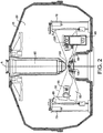
- Figure 2 shows a sectional view along the line A-A' of Figure 1 , illustrating the arrangement of the XRD components 20 in further detail.
- a vertical axis A defines a longitudal axis of the XRF tube 90 which has a rhodium tipped anode 130 located adjacent the sample holder 100.
- rhodium as an x-ray anode target material is, of course, merely one of a range of possible target materials, such as copper, tungsten, molybdenum and gold; the specific target material of the x-ray anode which is employed determines the energy distribution of the x-rays emitted from the XRF tube 90.
- the axis of the sample holder 100 is coterminous with the axis A of the XRF tube 90.
- the XRD tube 40 is mounted upon the right hand arm of the XRD goniometer 60 as viewed in Figure 2 .
- the XRD tube 40 is preferably a monochromatic source of x-rays which allows a well resolved diffraction pattern to be obtained, as described below.
- the XRD tube 40 also preferably has a relatively high power output in order to provide for the lowest detection limits. In the preferred embodiment, the power output of the XRD tube 40 is 1800 Watts at 45kV and 40mA.
- the XRD tube 40 has a tube window 220 (see also Figure 4a ) which communicates with XRD divergent optics 45 on the output thereof, to produce a divergent, monochromatic beam of x-rays that that irradiates the sample in the sample holder 100.
- the right hand goniometer driver 70 actuates the right hand arm of the XRD goniometer 60 so that the XRD tube 40 describes arcuate movement about the sample holder 100 wherein a sample is mounted.
- the general direction of movement of the XRD tube on the goniometer arm is indicated by ⁇ D .
- the Bragg Law requirement that ⁇ and ⁇ are matched necessitates that a range of wavelengths or angle is available. The wider the range of angles ⁇ is available, the more information on the crystal structure may be obtained.
- the XRD detector 50 Mounted on the left hand arm (as viewed in Figure 2 ) of the XRD goniometer 60 is an XRD detector 50.
- the goniometer driver 70 allows the left hand XRD goniometer arm to drive the XRD detector 50 in an arcuate direction ⁇ D about the sample holder 100.
- the details of the XRD detector 50 do not form a part of the present invention as such and the skilled person will appreciate that any suitable XRD detection arrangement could be employed.
- the XRD detector comprises XRD receiving optics 55 including a monochromator crystal, a collimator (not shown) and a detector array 65.
- the monochromator crystal is positioned at a specific angle relative to the sample and the diffracted beam, such that a chosen characteristic wavelength from the XRD source 40 is selected and passes into the detector.
- this crystal isolates fluorescence x-rays from the XRF tube 90 (which can cause a huge background in XRD analysis), and also unwanted diffraction peaks, so that a diffraction pattern of the sample may be obtained by scanning of the XRD tube 40 and XRD detector 50. It is to be understood that the monochromator is not an essential feature of the XRD detector, however.
- the primary radiation from the XRD tube 40 could be filtered instead so as to provide a single wavelength beam (e.g., the Copper K alpha line).
- the monochromator can be omitted from the secondary beam particularly where the XRF tube 90 is not operating simultaneously (so that the problems of sample fluorescence creating a background during XRD analysis are avoided).
- the XRD tube 40 and XRD detector 50 are independently moveable via the goniometer drivers 70, but in a preferred embodiment a central controller governs arcuate movement of both so that a wide range of angles between the x-ray source from XRD tube 40 and the detection channel in the detector 50 can be achieved.
- the XRD and XRF components 20, 30 are in different planes (along different axes - see Figure 1 ), with separate x-ray tubes for each part of the system, there is significantly more room for movement of the XRD tube 40 and XRD detector 50, resulting in a total angle subtended between the source of x-rays from the XRD tube 40 and the XRD detector 50 down to around 7 degrees (approximately 3.5 degrees to the horizontal, on each side of the sample), up to as much as 80 degrees (40 degrees to the horizontal for the XRD tube 40 and XRD detector 50 respectively).
- Photons detected by the XRD detector 50 are counted and processed by electronic means which is not shown, to provide a diffractogram.
- FIG. 3 a section along the line B-B' of Figure 1 is shown. Again the XRF tube 90 is shown along the longitudinal axis A with the anode 130 shown adjacent to the sample in the sample holder 100.
- x-rays from the XRF tube 90 strike the sample in the sample holder 100 and this causes the emission of secondary x-rays.
- the sample holder 100 is itself rotatable to permit the sample orientation to be altered during investigation.
- Characteristic energies of fluorescence x-rays emitted from the sample are separated from the continuum of x-ray energies by, for example, Bragg reflection from the surface of a crystal.
- a static fluorescence detection channel operable on this basis is shown on the left hand side of Figure 3 .
- the static fluorescence detection channel comprises an XRF monochromator 140, an XRF scintillation detector 150, an XRF sealed or gas flow detector 160 such as a gas filled counter, and an XRF Bragg crystal 170.
- Fluorescence x-rays from the sample pass into the monochromator 140 and impinge on the Bragg crystal 170 which diffracts only one wavelength related to a specific element at a particular Bragg angle.
- the Bragg crystal 170 thus acts to monochromate and focus a beam of x-rays of the desired energy onto the detectors 150, 160.
- a number of static fluorescence channels such as that shown in the left hand side of Figure 3 may be employed to allow simultaneous selection and measurement of fluorescence x-rays of differing energies. Such an array of static channels is particularly useful when the apparatus 10 is set up to monitor, for example, the specific proportions of known elements within an industrial process such as the manufacture of steel or cement.
- a sequential fluorescence channel mounted upon an XRF goniometer 120 may additional or alternatively be provided and such an arrangement is shown on the right hand side of Figure 3 .
- the XRF detector 110 of Figure 1 is shown in more detail as, for example, a scintillation detector 190 and a flow proportional counter (FPC) detector 200. Each is mounted upon the XRF goniometer 120 along with a collimator 210.
- the XRF goniometer 120 is based upon a ⁇ -2 ⁇ rotation wherein a fluorescence spectrum with multiple wavelengths is collimated by a primary collimator in front of a flat crystal monochromator.
- the crystal diffracts only one wavelength pertaining to one specific element of interest at a given angle. This diffracted wavelength is then further collimated by a secondary collimator in front of the detector.
- the crystal is positioned at an angle ⁇ and the detector is located at an angle 2 ⁇ by means of an optical encoder mechanism. As the crystal is rotated, that is, as the angle ⁇ is changed, different wavelengths are diffracted at different angles and are identified by the detector moving in synchronisation at an angle of 2 ⁇ . In this manner, a complete spectrum may be obtained.
- a fixed XRF channel is designed for one specific wavelength in a static measurement.
- the XRF goniometer 120 acts as a sequential system wherein one wavelength at a time is measured during a scan.
- the monochromator or fixed XRF channel is on the other hand pre-aligned with a fixed crystal and fixed detector positions to pick up one specific wavelength.
- Preferred embodiments of the present invention allow for both an XRF goniometer 120 for flexible, sequential XRF measurements along with a plurality of fixed XRF channels for specific measurement/detection of a finite range of known elements (as well, of course, as the separate XRD components 20).
- Figure 4a a section along the line C-C' of Figure 1 is shown, though not to scale.
- Figure 4a shows a partial side and cutaway section of the XRD tube 40 along with associated cooling and power connections.
- the XRD tube 40 is mechanically and thermally isolated from the vacuum chamber 15 (unlike the XRF tube 90 which is suspended from the top of it).
- the former is capable of movement relative to the latter.
- the isolation of the XRD tube 40 from the vacuum chamber 15 also prevents thermal conduction, that is, prevents the vacuum chamber 15 from acting as a heat sink for the XRD tube 40.
- a high vacuum connection 230 to the XRD tube 40 is provided at an end thereof.
- a high voltage cable 240 extends transversely from this high vacuum connection 230 from the XRD tube 40 towards the vacuum chamber wall.
- the high vacuum connection and the cable as it extends from that are potted using an electrically insulating material such as an epoxy resin which may be doped with thermal conductor to assist with the cooling of the x-ray tube 40.
- An insulating stand off or flange 260 within the wall of the vacuum chamber 15 provides electrical isolation between the inside of the vacuum chamber 15 and atmosphere whilst at the same time providing a vacuum tight seal.
- a second high voltage connection 270 to an external power supply (not shown) is provided.
- water cooling to the x-ray tube is effected by a water cooling inlet 280 and a water cooling outlet 290.
- Both inlet and outlet are formed of pipes or conduits which are at least partly flexible to allow movement of the XRD tube 40 relative to the vacuum chamber 15.
- vacuum tight feed throughs or flanges are also provided in the walls of the vacuum chamber 15 to allow connection of an external water supply.
Landscapes
- Chemical & Material Sciences (AREA)
- Physics & Mathematics (AREA)
- General Health & Medical Sciences (AREA)
- Life Sciences & Earth Sciences (AREA)
- Analytical Chemistry (AREA)
- Biochemistry (AREA)
- Health & Medical Sciences (AREA)
- General Physics & Mathematics (AREA)
- Immunology (AREA)
- Pathology (AREA)
- Crystallography & Structural Chemistry (AREA)
- Dispersion Chemistry (AREA)
- Spectroscopy & Molecular Physics (AREA)
- Analysing Materials By The Use Of Radiation (AREA)
Description
- This invention relates to an X-ray analysis instrument for carrying out elemental and crystallographic analysis in a sample.
- A variety of techniques are established in the art for analysing both the elemental and structural characteristics of a material having a crystalline structure. For example, x-ray diffraction (XRD) relies upon analysis of the pattern produced by diffraction of x-rays through the closely spaced lattice of atoms in a crystal to reveal the structural constituency of the analysed material. Bragg's law allows the spacing in the crystal lattice to be inferred from the measured path difference for diffracted x-rays.
- X-Ray fluorescence (XRF), by contrast, is a spectroscopic technique to allow elemental investigation of a sample without the need for chemical analysis. In XRF, illumination of a sample with an x-ray beam results in emission of secondary x-rays having characteristic wavelengths which are indicative of the elemental constituency of the sample. In order to permit multi elemental analysis, the x-ray source for XRF is typically polychromatic.
- Combined XRD/XRF instruments have existed for many years. A first type of combined XRD/XRF instrument operates with the sample at atmospheric pressure. A second type of combined instrument operates in vacuo. Each type has advantages and disadvantages: instruments wherein the sample is analysed in a vacuum tend to provide an enhanced x-ray analysis particularly though not exclusively for XRF where the sensitivity to elements having a low atomic number is increased. On the other hand, the size and physical arrangement of a non-vacuum instrument is less constrained, and moreover changing of samples can be carried out more promptly.
- For high quality XRD and a more complete structural characterisation for mineralogy and phase analysis, it is desirable to be able to change the measurable angle of diffraction through a wide range. In a non-vacuum system this does not present too much difficulty. However in a vacuum chamber the restricted space limits the opportunity to improve performance.
- Several solutions to the problem of limited space when analysing a sample in a vacuum chamber using XRD techniques are proposed in the art.
- In XRD-only devices, the x-ray tube and detector may be rotated with the sample fixed. For combined XRD/XRF devices however, a single x-ray tube is held in a fixed location relative to the vacuum chamber and the sample is rotated whilst the detector is held fixed, the sample is held fixed whilst the detector is rotated, or, as in
US-A-4,263,510 ,US-A-5,369,275 andUS-A-4,916,720 , the sample and detector are both rotated. The latter arrangement appears to provide the highest performance in vacuo. - For high quality XRF, however, the distance between the sample and the tube needs to be small. Unfortunately this requirement forces a compromise in a combined XRD/XRF instrument since, as noted, the highest quality XRD measurements require the sample to be rotatable. This in turn puts a minimum distance requirement on the location of the x-ray tube relative to the sample (to avoid collisions between the two during XRD measurements), so reducing the maximum performance during XRF measurements.
- Commonly assigned
US-A-5,406,608 describes a combined XRD/XRF analyser for analysing samples in vacuo. An x-ray source is mounted in fixed relation to a vacuum chamber of the instrument and provides a polychromatic divergent x-ray beam which illuminates a sample to permit both XRD and XRF measurements. One or more fixed and/or moveable fluorescence channels are provided so as to allow selection of x-rays of a particular wavelength and energy, and to detect the selected x-ray. A diffraction channel is also provided which allows selection of a characteristic x-ray wavelength at the source following diffraction by the sample. The diffraction channel also has a detection arrangement. The x-ray diffraction detector is rotatable to improve XRD measurements. XRF performance is however optimised by providing multiple fluorescence channels or by mounting a fluorescence channel (incorporating a detection arrangement) on a goniometer rotatable about the sample. - Whilst the foregoing arrangement provides a fair compromise between XRD and XRF performance, it does however suffer from a number of drawbacks. Firstly, the sample is fixed relative to the x-ray tube (in other words only the XRD detector arrangement is rotatable, not the sample) which limits XRD performance. Secondly, in seeking to avoid compromising the XRF performance, the arrangement of tube, sample detectors and vacuum chamber in
US-A-5,406,608 restricts the angular range of the XRD detector which in turn limits the ability to perform more extensive XRD measurements. - Against the foregoing background, it is an object of the present invention to provide an improved XRD/XRF analysis instrument for analysis of samples in vacuo. According to the present invention there is provided an apparatus for carrying out both x-ray diffraction (XRD) and x-ray fluorescence (XRF) analysis of a crystalline sample, in accordance with claim 1. This comprises: an evacuable chamber; a sample holder located within the evacuable chamber, for mounting the crystalline sample so that it may be analysed; an x-ray fluorescence source mounted within the evacuable chamber, for illuminating the crystalline sample with x-rays; an XRF detection arrangement for detecting secondary x-rays emitted from the surface of the crystalline sample as a result of illumination by x-rays from the said x-ray fluorescence source; an x-ray diffraction source, also mounted within the evacuable chamber but separate from the x-ray fluorescence source, for illuminating the crystalline sample with x-rays; an XRD detection arrangement for detecting x-rays of a characteristic wavelength which have been diffracted by the crystalline sample; and a moveable XRD support assembly, comprising a first part configured to mount the XRD source for relative movement between the XRD source and the sample holder, and a second part configured to mount the XRD detection arrangement for relative movement between the XRD detection arrangement and the sample holder. The apparatus in accordance with the invention thus provides separate x-ray tubes within the vacuum chamber, a first for illuminating the sample with x-rays for XRF and a second for illuminating the sample with x-rays for XRD. The XRD tube and the corresponding XRD detection arrangement are both mounted for relative movement with respect to the sample. The apparatus is therefore capable of acquiring XRF data for complete chemical or elemental analysis while the XRD data provide the complete structural or phase analysis on the same sample within the same embodiment under vacuum.
- Previous combined XRD and XRF arrangements have either compromised on accuracy and/or ability to measure low atomic number elements by having the sample at atmosphere, or have used a single static x-ray tube in vacuo, for both XRD and XRF. The latter arrangements result in compromises: either the range of angles of XRD measurements is limited (for example, where the XRD detector is moveable as in the arrangement of
US-A-5,406,608 , the range of available angles is between about 25 and 55 degrees), and/or the proximity of the x-ray source to the sample, for XRF measurements is limited, since the requirement to rotate the sample forces the x-ray tube to be backed off from the sample (to prevent collisions) which limits XRF performance. - It is well known by those skilled in the art that increasing the number of x-ray tubes is difficult in a vacuum chamber because of the additional cooling requirements. For accurate XRD measurements, an x-ray source of 1kW or more is recommended; the preferred embodiment is a 1.8kW source operating at 45kV and 40mA. Mounting a powerful x-ray source within vacuum complicates the problem of cooling the source as the available surface area through which heat can be transferred is reduced. It is therefore desirable to mount as much of the x-ray tube outside the vacuum chamber as possible to allow heat transfer out of the tube. However for a combined XRD-XRF instrument, the XRD detector must be mounted on the same side of the sample as is the tube, and must be displaced away from the sample. This displacement is required so that diffracted x-rays have diverged before reaching the detector so that the detector can have improved angular resolution. The distance between the sample and the detector should be maintained under vacuum and so the sample must be well inside the vacuum chamber. This then means that a fixed x-ray tube must also protrude deep inside the vacuum chamber and only one end of the x-ray tube is accessible from outside the vacuum chamber, exacerbating the heat transfer problem. This problem is further compounded if that x-ray tube must be rotatable within vacuum as there then cannot be any part of the tube that abuts the housing, and the tube is fully enclosed within vacuum. Previous combined XRD-XRF instruments have been restricted either by using the same fixed x-ray tube for both XRD and XRF, or by using two fixed x-ray tubes and rotating the sample and the XRD detector when performing XRD analysis.
- Additionally, increasing the number of x-ray sources requires increased space within the vacuum chamber. Space is at a premium in a vacuum chamber because increasing the size of the vacuum chamber increases its manufacturing cost and requires larger capacity, more expensive, vacuum pumps. Furthermore, as
US-A-5,406,608 and other prior art documents also acknowledge, a single x-ray source minimizes cost. - However, the inventors have realised that, if a second tube is provided for XRD, which is moveable relative to the sample and a moveable XRD detection arrangement is provided as well, a much wider range of diffraction angles can be measured. Preferred embodiments permit a range of a few degrees (eg, 7 degrees) up to about 80 degrees to be measured. At the same time the separate XRD tube and detection arrangement avoids the need to compromise with XRF, so that, in preferred embodiments the (separate) XRF tube can be mounted in fixed, close proximity to the sample in the sample holder (which may, nonetheless, be journalled for rotation about a vertical axis).
- By having the XRD apparatus in vacuo, the sample can be isolated from, for example, moisture ingress. This in turn assists in the analysis of certain industrial compounds such as cement and its constituents (eg, free lime) which are very hygroscopic and thus rapidly deteriorate in the presence of water in moist air.
- By having the sample fixed horizontally, powder samples can be accommodated without spillage. Prior art configurations where the sample holder rotates are either limited in the types of samples that they can analyse, or must restrict the sample angle rotation, limiting the performance of the XRD measurements able to be made. Powder samples are commonly analysed in the cement industry, for example.
- Preferably the XRD tube and XRD detection arrangement are each mounted upon separate arms of a single goniometer. Alternatively, two separate goniometers may be utilised so that the motions of the XRD source and XRD detector may be operated independently, though it is preferable that both motions be controlled by a single controller such as a computer. The XRD tube is preferably located wholly within the vacuum chamber so that its angular motion is unrestricted, and in that case the appropriate power and cooling facilities may be provided by employing high vacuum feed-throughs from external of the vacuum chamber into the interior thereof, with, optionally, flexible conduits within the chamber so that the XRD tube may move relative to the chamber.
- A significant advantage of such a fully integrated XRD and XRF apparatus is the synergy of chemical analysis data to interpret the XRD data for mineral analysis in that the XRF data is provided as additional input to the XRD processing system in order to validate and quantify the corresponding minerals or phases in the same sample. A single operating system preferably collects the data from both XRF and XRD modes of the instrument which is then processed to obtain a complete chemical and mineral characterization of the polycrystalline material.
- The invention may be put into practice in a number of ways, and a specific embodiment will now be described by way of example only and with reference to the accompanying figures in which:
-
Figure 1 shows a top view of a combined XRD/XRF apparatus embodying the present invention and including both XRD and XRF tubes and detectors; -
Figure 2 shows a sectional view along a line A-A' ofFigure 1 , further illustrating the arrangement of the XRD tube and detector; -
Figure 3 shows a sectional view along the line B-B' ofFigure 1 , further illustrating the arrangement of the XRF tube and detectors; -
Figure 4a shows a sectional view along the line C-C' ofFigure 1 , illustrating the XRD tube in further detail together with its manner of connection with and through the vacuum housing; and -
Figure 4b shows a side view of the arrangement ofFigure 4a . - Referring first to
Figure 1 , a schematic top view of a combined XRD/XRF apparatus 10 is shown. Theapparatus 10 includes avacuum chamber 15 containing XRD components, labelled generally at 20, and described in further detail below as well as in connection withFigure 2 , and separate XRF components indicated generally at 30 and described below in connection withFigure 3 . - The
XRD components 20, in more detail, comprise anXRD tube 40 and anXRD detector 50, each of which is mounted upon a respective arm of anXRD goniometer 60. Thegoniometer 60 and theXRD tube 40 andXRD detector 50 mounted upon it are moveable relative to a vertical axis A (passing into the paper as viewed inFigure 1 ) in a manner to be described subsequently. The axis A also defines the centre of asample holder 100 which, in use, holds a crystalline sample (not shown) to be analysed. - Associated with the
XRD goniometer 60 aregoniometer drivers 70 which may, for example, be manually or computer controlled to drive theXRD goniometer 60 to a chosen angular position. Finally,Figure 1 also illustrates schematically the location of cooling andpower conduits 80, for providing cooling and electrical power to theXRD tube 40. As may be seen from the plan view ofFigure 1 , theXRD tube 40 is physically isolated from the walls of thevacuum chamber 15 so its motion may be unimpeded. Thevacuum chamber 15 itself is, in use, evacuated using standard pumping equipment which will be familiar to those of ordinary skill and which is not illustrated inFigure 1 . - The
separate XRF components 30 comprise, in brief, anXRF tube 90 which is fixed relative to thesample holder 100 and thevacuum chamber 15, and is located coaxially with the axis A of thesample holder 100. TheXRF components 30 also include anXRF detector 110 mounted upon anXRF goniometer 120. Instead of asingle XRF detector 110 mounted upon anXRF goniometer 120 so that thedetector 110 may be moved, a plurality of fixed XRF channels may instead be located at spatially separate places within thevacuum chamber 15, to allow simultaneous selection and measurement of fluorescence x-rays from the sample of differing energies. The details of the XRF detector do not, however, form a part of the present invention and any suitable known arrangement may be employed, such as that which is described in detail in commonly assignedUS-A-5,406,608 , the contents of which are incorporated by reference in their entirety. -
Figure 2 shows a sectional view along the line A-A' ofFigure 1 , illustrating the arrangement of theXRD components 20 in further detail. As described above in connection withFigure 1 , a vertical axis A defines a longitudal axis of theXRF tube 90 which has a rhodium tippedanode 130 located adjacent thesample holder 100. The use of rhodium as an x-ray anode target material is, of course, merely one of a range of possible target materials, such as copper, tungsten, molybdenum and gold; the specific target material of the x-ray anode which is employed determines the energy distribution of the x-rays emitted from theXRF tube 90. - As may be seen more clearly in
Figure 2 , the axis of thesample holder 100 is coterminous with the axis A of theXRF tube 90. - The
XRD tube 40 is mounted upon the right hand arm of theXRD goniometer 60 as viewed inFigure 2 . TheXRD tube 40 is preferably a monochromatic source of x-rays which allows a well resolved diffraction pattern to be obtained, as described below. TheXRD tube 40 also preferably has a relatively high power output in order to provide for the lowest detection limits. In the preferred embodiment, the power output of theXRD tube 40 is 1800 Watts at 45kV and 40mA. - The
XRD tube 40 has a tube window 220 (see alsoFigure 4a ) which communicates with XRD divergent optics 45 on the output thereof, to produce a divergent, monochromatic beam of x-rays that that irradiates the sample in thesample holder 100. - In use, the right
hand goniometer driver 70 actuates the right hand arm of theXRD goniometer 60 so that theXRD tube 40 describes arcuate movement about thesample holder 100 wherein a sample is mounted. The general direction of movement of the XRD tube on the goniometer arm is indicated by θD. The angle between the sample (strictly, the crystal plans within the sample) and the XRD tube defines the diffraction in accordance with Braggs's Law: nλ = 2dhk1 Sinθ1 where n is an integral number of wavelengths λ, θ1 is the angle of diffraction, and dhk1 is the interplanar distance dependent upon the Miller indices h, k and 1 of the crystal. The Bragg Law requirement that θ and λ are matched necessitates that a range of wavelengths or angle is available. The wider the range of angles θ is available, the more information on the crystal structure may be obtained. - Mounted on the left hand arm (as viewed in
Figure 2 ) of theXRD goniometer 60 is anXRD detector 50. As with theXRD tube 40, thegoniometer driver 70 allows the left hand XRD goniometer arm to drive theXRD detector 50 in an arcuate direction θD about thesample holder 100. The details of theXRD detector 50 do not form a part of the present invention as such and the skilled person will appreciate that any suitable XRD detection arrangement could be employed. In brief, however, the XRD detector comprisesXRD receiving optics 55 including a monochromator crystal, a collimator (not shown) and adetector array 65. The monochromator crystal is positioned at a specific angle relative to the sample and the diffracted beam, such that a chosen characteristic wavelength from theXRD source 40 is selected and passes into the detector. When theapparatus 10 embodying the present invention is operated in combined XRD/XRF mode (that is, with both XRD and XRF analyses taking place simultaneously), this crystal isolates fluorescence x-rays from the XRF tube 90 (which can cause a huge background in XRD analysis), and also unwanted diffraction peaks, so that a diffraction pattern of the sample may be obtained by scanning of theXRD tube 40 andXRD detector 50. It is to be understood that the monochromator is not an essential feature of the XRD detector, however. For example, the primary radiation from theXRD tube 40 could be filtered instead so as to provide a single wavelength beam (e.g., the Copper K alpha line). In that case the monochromator can be omitted from the secondary beam particularly where theXRF tube 90 is not operating simultaneously (so that the problems of sample fluorescence creating a background during XRD analysis are avoided). - In one embodiment the
XRD tube 40 andXRD detector 50 are independently moveable via thegoniometer drivers 70, but in a preferred embodiment a central controller governs arcuate movement of both so that a wide range of angles between the x-ray source fromXRD tube 40 and the detection channel in thedetector 50 can be achieved. Importantly, because the XRD andXRF components Figure 1 ), with separate x-ray tubes for each part of the system, there is significantly more room for movement of theXRD tube 40 andXRD detector 50, resulting in a total angle subtended between the source of x-rays from theXRD tube 40 and theXRD detector 50 down to around 7 degrees (approximately 3.5 degrees to the horizontal, on each side of the sample), up to as much as 80 degrees (40 degrees to the horizontal for theXRD tube 40 andXRD detector 50 respectively). - Photons detected by the
XRD detector 50 are counted and processed by electronic means which is not shown, to provide a diffractogram. - Turning now to
Figure 3 , a section along the line B-B' ofFigure 1 is shown. Again theXRF tube 90 is shown along the longitudinal axis A with theanode 130 shown adjacent to the sample in thesample holder 100. - In use, x-rays from the
XRF tube 90 strike the sample in thesample holder 100 and this causes the emission of secondary x-rays. Thesample holder 100 is itself rotatable to permit the sample orientation to be altered during investigation. Characteristic energies of fluorescence x-rays emitted from the sample are separated from the continuum of x-ray energies by, for example, Bragg reflection from the surface of a crystal. A static fluorescence detection channel operable on this basis is shown on the left hand side ofFigure 3 . The static fluorescence detection channel comprises anXRF monochromator 140, anXRF scintillation detector 150, an XRF sealed orgas flow detector 160 such as a gas filled counter, and anXRF Bragg crystal 170. - Fluorescence x-rays from the sample pass into the
monochromator 140 and impinge on theBragg crystal 170 which diffracts only one wavelength related to a specific element at a particular Bragg angle. TheBragg crystal 170 thus acts to monochromate and focus a beam of x-rays of the desired energy onto thedetectors Figure 3 may be employed to allow simultaneous selection and measurement of fluorescence x-rays of differing energies. Such an array of static channels is particularly useful when theapparatus 10 is set up to monitor, for example, the specific proportions of known elements within an industrial process such as the manufacture of steel or cement. - The use of static fluorescence channels is, however, typically otherwise inflexible since each channel is configured to measure only a certainly energy (and hence, to identify a specific element). To overcome this drawback, therefore, a sequential fluorescence channel mounted upon an
XRF goniometer 120 may additional or alternatively be provided and such an arrangement is shown on the right hand side ofFigure 3 . TheXRF detector 110 ofFigure 1 is shown in more detail as, for example, ascintillation detector 190 and a flow proportional counter (FPC)detector 200. Each is mounted upon theXRF goniometer 120 along with acollimator 210. TheXRF goniometer 120 is based upon a θ-2θ rotation wherein a fluorescence spectrum with multiple wavelengths is collimated by a primary collimator in front of a flat crystal monochromator. The crystal diffracts only one wavelength pertaining to one specific element of interest at a given angle. This diffracted wavelength is then further collimated by a secondary collimator in front of the detector. The crystal is positioned at an angle θ and the detector is located at an angle 2θ by means of an optical encoder mechanism. As the crystal is rotated, that is, as the angle θ is changed, different wavelengths are diffracted at different angles and are identified by the detector moving in synchronisation at an angle of 2θ. In this manner, a complete spectrum may be obtained. By contrast a fixed XRF channel is designed for one specific wavelength in a static measurement. In other words, theXRF goniometer 120 acts as a sequential system wherein one wavelength at a time is measured during a scan. The monochromator or fixed XRF channel is on the other hand pre-aligned with a fixed crystal and fixed detector positions to pick up one specific wavelength. Preferred embodiments of the present invention allow for both anXRF goniometer 120 for flexible, sequential XRF measurements along with a plurality of fixed XRF channels for specific measurement/detection of a finite range of known elements (as well, of course, as the separate XRD components 20). - Turning finally to
Figure 4a , a section along the line C-C' ofFigure 1 is shown, though not to scale.Figure 4a shows a partial side and cutaway section of theXRD tube 40 along with associated cooling and power connections. As is apparent fromFigure 1 and the foregoing description, theXRD tube 40 is mechanically and thermally isolated from the vacuum chamber 15 (unlike theXRF tube 90 which is suspended from the top of it). By isolating theXRD tube 40 from thevacuum chamber 15, the former is capable of movement relative to the latter. The isolation of theXRD tube 40 from thevacuum chamber 15 also prevents thermal conduction, that is, prevents thevacuum chamber 15 from acting as a heat sink for theXRD tube 40. As such, however, it is desirable alternatively to cool theXRD tube 40. It is also necessary to supply power at relatively high voltages to theXRD tube 40 and the arrangement ofFigure 4a suggests one embodiment for doing this. As seen inFigure 4a , and also inFigure 4b which is a close up plan view of theXRD tube 40 as first shown inFigure 1 , a high vacuum connection 230 to theXRD tube 40 is provided at an end thereof. Ahigh voltage cable 240 extends transversely from this high vacuum connection 230 from theXRD tube 40 towards the vacuum chamber wall. The high vacuum connection and the cable as it extends from that are potted using an electrically insulating material such as an epoxy resin which may be doped with thermal conductor to assist with the cooling of thex-ray tube 40. - An insulating stand off or
flange 260 within the wall of thevacuum chamber 15 provides electrical isolation between the inside of thevacuum chamber 15 and atmosphere whilst at the same time providing a vacuum tight seal. On the atmosphere side of thevacuum chamber 15, a secondhigh voltage connection 270 to an external power supply (not shown) is provided. - Finally, water cooling to the x-ray tube is effected by a
water cooling inlet 280 and awater cooling outlet 290. Both inlet and outlet are formed of pipes or conduits which are at least partly flexible to allow movement of theXRD tube 40 relative to thevacuum chamber 15. Although not shown inFigures 4a or 4b , vacuum tight feed throughs or flanges are also provided in the walls of thevacuum chamber 15 to allow connection of an external water supply. - Although one specific embodiment of the present invention has been described for illustrative purposes only, the skilled person will understand that various modifications may be contemplated without departing from the scope of the invention which is defined in the accompanying claims.
Claims (13)
- An apparatus (10) for carrying out both x-ray diffraction (XRD) and x-ray fluorescence (XRF) analysis of a crystalline sample, comprising:an evacuable chamber (15);a sample holder (100) located within the evacuable chamber, for mounting the crystalline sample so that it may be analysed;an x-ray fluorescence source (90) mounted within the evacuable chamber, for illuminating the crystalline sample with x-rays;an XRF detection arrangement (110) for detecting secondary x-rays emitted from the surface of the crystalline sample as a result of illumination by x-rays from the said x-ray fluorescence source, the XRF detection arrangement (110), the sample holder (100) and the x-ray fluorescence source (90) being positioned in a first plane;an x-ray diffraction source (40), also mounted within the evacuable chamber but separate from the x-ray fluorescence source, for illuminating the crystalline sample with x-rays;an XRD detection arrangement (50) for detecting x-rays of a characteristic wavelength which have been diffracted by the crystalline sample, the XRD detection arrangement (50), the sample holder (100) and x-ray diffraction source (40) being positioned in a second plane; anda moveable XRD support assembly (60), comprising a first part configured to mount the XRD source for relative movement between the XRD source and the sample holder, and a second part configured to mount the XRD detection arrangement for relative movement between the XRD detection arrangement and the sample holder; andwherein the first and second planes are different.
- The apparatus of claim 1, wherein the first part of the moveable support assembly is configured to mount the XRD source (40) for rotatable movement through a plurality of angular positions relative to the sample holder, and wherein the second part of the moveable support assembly is configured to mount the XRD detection arrangement (50) for rotatable movement through a plurality of angular positions relative to the sample holder.
- The apparatus of claim 2, wherein the moveable support assembly comprises a goniometer (60), the first part of the moveable support assembly including a first arm of the goniometer and the second part of the moveable support assembly including a second arm of the goniometer.
- The apparatus of claim 3, further comprising goniometer actuating means (70) for actuating each of the first and second goniometer arms so as to control arcuate movement of the XRD source (40) and XRD detection arrangement (50), respectively, about the sample holder, between first and second end stop positions.
- The apparatus of claim 4, wherein the sample holder defines a horizontal plane within the evacuable chamber, wherein the first and second end stop positions of the XRD detection arrangement (50) subtend angles of approximately 3 degrees and 40 degrees to that horizontal plane respectively, and wherein the first and second end stop positions of the XRD source (40) subtend angles of approximately 3 degrees and 40 degrees to that horizontal plane respectively.
- The apparatus of any preceding claim, wherein the XRF source (90) is mounted in a fixed position relative to the sample holder and the evacuable chamber.
- The apparatus of claim 6, wherein the XRF tube has a longitudinal axis which intersects the sample holder.
- The apparatus of any preceding claim, wherein the sample holder is rotatable about an axis.
- The apparatus of any preceding claim, wherein the XRF detection arrangement (110) is mounted upon a moveable XRF support assembly (120).
- The apparatus of any preceding claim, wherein the XRD source (40) is housed wholly within the evacuable chamber.
- The apparatus of claim 10, further comprising a cooling channel (280,290) coupled from externally of the vacuum chamber to the XRD source (40) so as to supply cooling thereto, and a power connection (80) also coupled from externally of the vacuum chamber to the XRD source (40) for supplying power thereto.
- The apparatus of claim 11, wherein each of the cooling channel and the power connection is flexible along at least a part thereof so as to maintain power and cooling to the XRD source (40) as it moves relative to the vacuum chamber in use.
- The apparatus of any preceding claim, wherein the XRD source (40) is arranged to generate a monochromatic x-ray beam whereas the XRF source (90) is arranged to generate a polychromatic x-ray beam.
Applications Claiming Priority (2)
| Application Number | Priority Date | Filing Date | Title |
|---|---|---|---|
| GB0704322.7A GB2447252B (en) | 2007-03-06 | 2007-03-06 | X-ray analysis instrument |
| PCT/EP2008/001566 WO2008107108A1 (en) | 2007-03-06 | 2008-02-28 | X-ray analysis instrument |
Publications (2)
| Publication Number | Publication Date |
|---|---|
| EP2126553A1 EP2126553A1 (en) | 2009-12-02 |
| EP2126553B1 true EP2126553B1 (en) | 2016-04-13 |
Family
ID=37966025
Family Applications (1)
| Application Number | Title | Priority Date | Filing Date |
|---|---|---|---|
| EP08716095.8A Not-in-force EP2126553B1 (en) | 2007-03-06 | 2008-02-28 | X-ray analysis instrument |
Country Status (8)
| Country | Link |
|---|---|
| US (1) | US7983386B2 (en) |
| EP (1) | EP2126553B1 (en) |
| JP (1) | JP5301470B2 (en) |
| CN (1) | CN101669024B (en) |
| GB (1) | GB2447252B (en) |
| RU (1) | RU2450261C2 (en) |
| WO (1) | WO2008107108A1 (en) |
| ZA (1) | ZA200905811B (en) |
Cited By (2)
| Publication number | Priority date | Publication date | Assignee | Title |
|---|---|---|---|---|
| EP4019951A1 (en) | 2020-12-24 | 2022-06-29 | Inel S.A.S | Apparatuses and methods for combined simultaneous analyses of materials |
| US12105034B2 (en) | 2018-11-22 | 2024-10-01 | Rigaku Corporation | Single-crystal X-ray structure analysis apparatus, and method therefor |
Families Citing this family (33)
| Publication number | Priority date | Publication date | Assignee | Title |
|---|---|---|---|---|
| CN101776620B (en) * | 2009-05-11 | 2014-06-25 | 中国建材检验认证集团股份有限公司 | Bent crystal light splitting device of wavelength dispersion X-fluorescence spectrograph and operating method thereof |
| US7978820B2 (en) | 2009-10-22 | 2011-07-12 | Panalytical B.V. | X-ray diffraction and fluorescence |
| GB2476255B (en) * | 2009-12-17 | 2012-03-07 | Thermo Fisher Scient Ecublens Sarl | Method and apparatus for performing x-ray analysis of a sample |
| JP4914514B2 (en) | 2010-07-02 | 2012-04-11 | 株式会社リガク | X-ray fluorescence analyzer and method |
| CN101936929B (en) * | 2010-07-27 | 2012-05-23 | 中国石化集团华北石油局 | X-ray fluorescent element analysis device and mud logging unit thereof |
| WO2012050620A1 (en) * | 2010-10-14 | 2012-04-19 | Caldera Pharmaceuticals, Inc. | Method for analysis using x-ray flourescence |
| JP5838109B2 (en) * | 2011-05-13 | 2015-12-24 | 株式会社リガク | Compound X-ray analyzer |
| US9952165B2 (en) * | 2012-04-19 | 2018-04-24 | University Of Leicester | Methods and apparatus for X-ray diffraction |
| US10697908B2 (en) | 2015-06-01 | 2020-06-30 | Xwinsys Ltd. | Metrology inspection apparatus |
| US10175184B2 (en) | 2015-06-22 | 2019-01-08 | Moxtek, Inc. | XRF analyzer for light element detection |
| CN107437487A (en) * | 2016-05-25 | 2017-12-05 | 宝山钢铁股份有限公司 | One kind is used for sample platform of scanning electronic microscope lifting anticollision device, collision-prevention device |
| WO2018086853A1 (en) * | 2016-11-09 | 2018-05-17 | Imec Vzw | Apparatus for combined stem and eds tomography |
| CN106646585B (en) * | 2017-01-24 | 2023-12-22 | 中国工程物理研究院激光聚变研究中心 | Quasi-monoenergetic X-ray calibration platform |
| CN108572185B (en) * | 2017-03-13 | 2024-07-26 | 中国科学院兰州化学物理研究所 | Low-temperature microscopic sample loading system for easily-weathered crystals of X-ray single crystal diffractometer |
| EP3619525B1 (en) * | 2017-05-16 | 2025-08-27 | FCT - ACTECH Pty Ltd. | Method and apparatus for analysing particulate material |
| CN107228871B (en) * | 2017-07-21 | 2023-07-04 | 中国地质大学(武汉) | Portable X-ray analysis device |
| CN108267467A (en) * | 2018-03-26 | 2018-07-10 | 中国地质大学(武汉) | A kind of portable multi-purpose X-ray analyzer |
| CA3097466A1 (en) * | 2018-04-20 | 2019-10-24 | Outotec (Finland) Oy | X-ray fluorescence analyzer, and a method for performing x-ray fluorescence analysis |
| SE544318C2 (en) * | 2018-04-20 | 2022-04-05 | Outotec Finland Oy | X-ray fluorescence analyzer for analysis of small concentrations of element in slurry |
| US11592407B2 (en) | 2018-05-18 | 2023-02-28 | Enersoft Inc. | Systems, devices, and methods for x-ray fluorescence analysis of geological samples |
| KR102718046B1 (en) * | 2018-07-04 | 2024-10-17 | 가부시키가이샤 리가쿠 | X-ray Fluorescence Spectrometer |
| FI131496B1 (en) * | 2018-10-19 | 2025-05-23 | Commw Scient Ind Res Org | An energy dispersive x-ray diffraction analyser having an improved reflection geometry |
| JP7217943B2 (en) | 2019-04-11 | 2023-02-06 | 株式会社リガク | Projection image capturing method, control device, control program, processing device and processing program |
| JP2023536448A (en) | 2020-07-29 | 2023-08-25 | ジェモロジカル インスティテュート オブ アメリカ インコーポレイテッド(ジーアイエー) | UV-visible absorption spectroscopy for gem identification |
| WO2022058912A1 (en) | 2020-09-16 | 2022-03-24 | Enersoft Inc. | Multiple-sensor analysis of geological samples |
| CN113125471B (en) * | 2021-03-31 | 2023-06-27 | 武汉联影生命科学仪器有限公司 | Scanning system and scanning control method |
| WO2022266779A1 (en) | 2021-06-25 | 2022-12-29 | Enersoft Inc. | Laser induced breakdown spectroscopy for geological analysis |
| CN114062406B (en) * | 2022-01-04 | 2022-03-22 | 中国工程物理研究院流体物理研究所 | Time-resolved polycrystalline X-ray diffraction target device |
| CN114486971A (en) * | 2022-01-25 | 2022-05-13 | 深圳市埃芯半导体科技有限公司 | Multi-source designed X-ray analysis system and method |
| DE112023002079T5 (en) * | 2022-05-02 | 2025-02-27 | Sigray, Inc. | SEQUENTIAL WAVELENGTH-DISPERSIVE X-RAY SPECTROMETER |
| IL301287B2 (en) * | 2023-03-09 | 2026-01-01 | Rigaku Semiconductor Instr Ltd | Dual head x-ray inspection system |
| CN116879335B (en) * | 2023-09-08 | 2023-11-17 | 四川大学 | Combined scanning XRD/XRF comprehensive imaging method |
| CN119395060B (en) * | 2024-10-31 | 2025-12-05 | 中国科学院物理研究所 | An automated XRD testing system |
Citations (3)
| Publication number | Priority date | Publication date | Assignee | Title |
|---|---|---|---|---|
| FR649940A (en) * | 1927-03-28 | 1928-12-29 | Philips Nv | X-ray installation |
| US2462374A (en) * | 1944-10-04 | 1949-02-22 | Philips Lab Inc | Stress analysis by x-ray diffraction |
| US4916720A (en) * | 1987-11-27 | 1990-04-10 | Horiba, Ltd. | X-ray analyzer |
Family Cites Families (13)
| Publication number | Priority date | Publication date | Assignee | Title |
|---|---|---|---|---|
| US3344274A (en) * | 1967-09-26 | Ray analysis apparatus having both diffraction amd spectrometer tubes mounted on a common housing | ||
| US4263510A (en) * | 1979-07-30 | 1981-04-21 | General Electric Company | Combined x-ray diffraction and fluorescence spectroscopy apparatus with environmentally controllable chamber |
| SU1257482A1 (en) * | 1984-07-03 | 1986-09-15 | Ордена Трудового Красного Знамени Институт Кристаллографии Им.А.В.Шубникова | X-ray diffraction method of analyzing structure disarrangements in thin near-surface layers of crystals |
| JPS63167251A (en) * | 1986-12-27 | 1988-07-11 | Shimadzu Corp | X-ray analyzer |
| JPH0739987B2 (en) * | 1988-06-28 | 1995-05-01 | 川崎製鉄株式会社 | Simultaneous measurement of film thickness and composition |
| EP0523566B1 (en) * | 1991-07-11 | 2001-11-21 | International Superconductivity Technology Center | Apparatus for solid surface analysis using x-ray spectroscopy |
| GB9223592D0 (en) * | 1992-11-11 | 1992-12-23 | Fisons Plc | X-ray analysis apparatus |
| WO1997013142A1 (en) * | 1995-10-03 | 1997-04-10 | Philips Electronics N.V. | Apparatus for simultaneous x-ray diffraction and x-ray fluorescence measurements |
| JP2002131251A (en) * | 2000-10-20 | 2002-05-09 | Seiko Instruments Inc | X-ray analyzer |
| JP2003098126A (en) * | 2001-09-26 | 2003-04-03 | Rigaku Industrial Co | X-ray analyzer for both fluorescence and diffraction |
| CN1270176C (en) * | 2002-12-02 | 2006-08-16 | 中国科学技术大学 | Method and apparatus for measuring and analyzing structure and component of combined sample |
| US7092843B2 (en) * | 2003-10-21 | 2006-08-15 | X-Ray Optical Systems, Inc. | Apparatus and method for suppressing insignificant variations in measured sample composition data, including data measured from dynamically changing samples using x-ray analysis techniques |
| JP3912606B2 (en) * | 2004-10-26 | 2007-05-09 | 株式会社リガク | X-ray thin film inspection apparatus, thin film inspection apparatus for product wafer and method thereof |
-
2007
- 2007-03-06 GB GB0704322.7A patent/GB2447252B/en active Active
-
2008
- 2008-02-28 WO PCT/EP2008/001566 patent/WO2008107108A1/en not_active Ceased
- 2008-02-28 US US12/529,114 patent/US7983386B2/en not_active Expired - Fee Related
- 2008-02-28 JP JP2009552103A patent/JP5301470B2/en not_active Expired - Fee Related
- 2008-02-28 CN CN200880007232.2A patent/CN101669024B/en not_active Expired - Fee Related
- 2008-02-28 EP EP08716095.8A patent/EP2126553B1/en not_active Not-in-force
- 2008-02-28 RU RU2009136636/28A patent/RU2450261C2/en not_active IP Right Cessation
-
2009
- 2009-08-21 ZA ZA200905811A patent/ZA200905811B/en unknown
Patent Citations (3)
| Publication number | Priority date | Publication date | Assignee | Title |
|---|---|---|---|---|
| FR649940A (en) * | 1927-03-28 | 1928-12-29 | Philips Nv | X-ray installation |
| US2462374A (en) * | 1944-10-04 | 1949-02-22 | Philips Lab Inc | Stress analysis by x-ray diffraction |
| US4916720A (en) * | 1987-11-27 | 1990-04-10 | Horiba, Ltd. | X-ray analyzer |
Cited By (4)
| Publication number | Priority date | Publication date | Assignee | Title |
|---|---|---|---|---|
| US12105034B2 (en) | 2018-11-22 | 2024-10-01 | Rigaku Corporation | Single-crystal X-ray structure analysis apparatus, and method therefor |
| EP3885747B1 (en) * | 2018-11-22 | 2026-04-29 | Rigaku Corporation | Single-crystal x-ray structural analysis device and method therefor |
| EP4019951A1 (en) | 2020-12-24 | 2022-06-29 | Inel S.A.S | Apparatuses and methods for combined simultaneous analyses of materials |
| US11796492B2 (en) | 2020-12-24 | 2023-10-24 | Inel S.A.S. | Apparatuses and methods for combined simultaneous analyses of materials |
Also Published As
| Publication number | Publication date |
|---|---|
| CN101669024A (en) | 2010-03-10 |
| US20100111251A1 (en) | 2010-05-06 |
| GB0704322D0 (en) | 2007-04-11 |
| GB2447252A (en) | 2008-09-10 |
| ZA200905811B (en) | 2010-06-30 |
| WO2008107108A1 (en) | 2008-09-12 |
| RU2450261C2 (en) | 2012-05-10 |
| JP2010520467A (en) | 2010-06-10 |
| WO2008107108A8 (en) | 2009-09-11 |
| CN101669024B (en) | 2012-10-31 |
| JP5301470B2 (en) | 2013-09-25 |
| GB2447252B (en) | 2012-03-14 |
| EP2126553A1 (en) | 2009-12-02 |
| RU2009136636A (en) | 2011-04-20 |
| US7983386B2 (en) | 2011-07-19 |
Similar Documents
| Publication | Publication Date | Title |
|---|---|---|
| EP2126553B1 (en) | X-ray analysis instrument | |
| EP2315009B1 (en) | X-Ray diffraction and fluorescence | |
| US11105756B2 (en) | X-ray diffraction and X-ray spectroscopy method and related apparatus | |
| CN102770753B (en) | The method and apparatus carrying out the X-ray analysis of sample | |
| US9823203B2 (en) | X-ray surface analysis and measurement apparatus | |
| US5406608A (en) | X-ray analysis apparatus | |
| Kavčič et al. | Design and performance of a versatile curved-crystal spectrometer for high-resolution spectroscopy in the tender x-ray range | |
| EP3627146A1 (en) | X-ray spectrometer | |
| US20150247811A1 (en) | X-ray surface analysis and measurement apparatus | |
| US6665372B2 (en) | X-ray diffractometer | |
| US11796492B2 (en) | Apparatuses and methods for combined simultaneous analyses of materials | |
| EP2589956B1 (en) | X-ray fluorescence analyzing method | |
| US10094790B2 (en) | Measurement chamber for a compact goniometer in an x-ray spectrometer | |
| CN1620602A (en) | Diffractometer and method for diffraction analysis | |
| JP5740401B2 (en) | X-ray diffraction method and apparatus | |
| RU72328U1 (en) | COMBINED DEVICE FOR X-RAY STRUCTURAL AND X-RAY SPECTRUM MEASUREMENTS (OPTIONS) | |
| US6546069B1 (en) | Combined wave dispersive and energy dispersive spectrometer | |
| JP2003329619A (en) | Apparatus for observing sample surface by X-ray and method for evaluating crystal state of metal by X-ray | |
| JP2000206061A (en) | Fluorescent x-ray measuring device | |
| US7035377B2 (en) | X-ray generator and adjusting method of the same | |
| Fukumoto et al. | Three‐Dimensional X‐Ray Diffraction Analysis Using Energy‐Dispersive X‐Ray Detector and Straight Capillary Optics | |
| Manti et al. | Recent Developments of the VOXES Von Hamos X-ray Spectrometer for Laboratory XES and XAS Studies | |
| JPH0196542A (en) | Analysis of crystal structure |
Legal Events
| Date | Code | Title | Description |
|---|---|---|---|
| PUAI | Public reference made under article 153(3) epc to a published international application that has entered the european phase |
Free format text: ORIGINAL CODE: 0009012 |
|
| 17P | Request for examination filed |
Effective date: 20091005 |
|
| AK | Designated contracting states |
Kind code of ref document: A1 Designated state(s): AT BE BG CH CY CZ DE DK EE ES FI FR GB GR HR HU IE IS IT LI LT LU LV MC MT NL NO PL PT RO SE SI SK TR |
|
| DAX | Request for extension of the european patent (deleted) | ||
| 17Q | First examination report despatched |
Effective date: 20100805 |
|
| GRAP | Despatch of communication of intention to grant a patent |
Free format text: ORIGINAL CODE: EPIDOSNIGR1 |
|
| INTG | Intention to grant announced |
Effective date: 20151023 |
|
| GRAS | Grant fee paid |
Free format text: ORIGINAL CODE: EPIDOSNIGR3 |
|
| GRAA | (expected) grant |
Free format text: ORIGINAL CODE: 0009210 |
|
| AK | Designated contracting states |
Kind code of ref document: B1 Designated state(s): AT BE BG CH CY CZ DE DK EE ES FI FR GB GR HR HU IE IS IT LI LT LU LV MC MT NL NO PL PT RO SE SI SK TR |
|
| REG | Reference to a national code |
Ref country code: GB Ref legal event code: FG4D |
|
| REG | Reference to a national code |
Ref country code: AT Ref legal event code: REF Ref document number: 790669 Country of ref document: AT Kind code of ref document: T Effective date: 20160415 Ref country code: CH Ref legal event code: EP |
|
| REG | Reference to a national code |
Ref country code: IE Ref legal event code: FG4D |
|
| REG | Reference to a national code |
Ref country code: NL Ref legal event code: FP |
|
| REG | Reference to a national code |
Ref country code: DE Ref legal event code: R096 Ref document number: 602008043489 Country of ref document: DE |
|
| REG | Reference to a national code |
Ref country code: LT Ref legal event code: MG4D |
|
| REG | Reference to a national code |
Ref country code: AT Ref legal event code: MK05 Ref document number: 790669 Country of ref document: AT Kind code of ref document: T Effective date: 20160413 |
|
| PG25 | Lapsed in a contracting state [announced via postgrant information from national office to epo] |
Ref country code: NO Free format text: LAPSE BECAUSE OF FAILURE TO SUBMIT A TRANSLATION OF THE DESCRIPTION OR TO PAY THE FEE WITHIN THE PRESCRIBED TIME-LIMIT Effective date: 20160713 Ref country code: FI Free format text: LAPSE BECAUSE OF FAILURE TO SUBMIT A TRANSLATION OF THE DESCRIPTION OR TO PAY THE FEE WITHIN THE PRESCRIBED TIME-LIMIT Effective date: 20160413 Ref country code: PL Free format text: LAPSE BECAUSE OF FAILURE TO SUBMIT A TRANSLATION OF THE DESCRIPTION OR TO PAY THE FEE WITHIN THE PRESCRIBED TIME-LIMIT Effective date: 20160413 Ref country code: LT Free format text: LAPSE BECAUSE OF FAILURE TO SUBMIT A TRANSLATION OF THE DESCRIPTION OR TO PAY THE FEE WITHIN THE PRESCRIBED TIME-LIMIT Effective date: 20160413 |
|
| PG25 | Lapsed in a contracting state [announced via postgrant information from national office to epo] |
Ref country code: HR Free format text: LAPSE BECAUSE OF FAILURE TO SUBMIT A TRANSLATION OF THE DESCRIPTION OR TO PAY THE FEE WITHIN THE PRESCRIBED TIME-LIMIT Effective date: 20160413 Ref country code: PT Free format text: LAPSE BECAUSE OF FAILURE TO SUBMIT A TRANSLATION OF THE DESCRIPTION OR TO PAY THE FEE WITHIN THE PRESCRIBED TIME-LIMIT Effective date: 20160816 Ref country code: SE Free format text: LAPSE BECAUSE OF FAILURE TO SUBMIT A TRANSLATION OF THE DESCRIPTION OR TO PAY THE FEE WITHIN THE PRESCRIBED TIME-LIMIT Effective date: 20160413 Ref country code: GR Free format text: LAPSE BECAUSE OF FAILURE TO SUBMIT A TRANSLATION OF THE DESCRIPTION OR TO PAY THE FEE WITHIN THE PRESCRIBED TIME-LIMIT Effective date: 20160714 Ref country code: LV Free format text: LAPSE BECAUSE OF FAILURE TO SUBMIT A TRANSLATION OF THE DESCRIPTION OR TO PAY THE FEE WITHIN THE PRESCRIBED TIME-LIMIT Effective date: 20160413 Ref country code: AT Free format text: LAPSE BECAUSE OF FAILURE TO SUBMIT A TRANSLATION OF THE DESCRIPTION OR TO PAY THE FEE WITHIN THE PRESCRIBED TIME-LIMIT Effective date: 20160413 Ref country code: ES Free format text: LAPSE BECAUSE OF FAILURE TO SUBMIT A TRANSLATION OF THE DESCRIPTION OR TO PAY THE FEE WITHIN THE PRESCRIBED TIME-LIMIT Effective date: 20160413 |
|
| PG25 | Lapsed in a contracting state [announced via postgrant information from national office to epo] |
Ref country code: BE Free format text: LAPSE BECAUSE OF FAILURE TO SUBMIT A TRANSLATION OF THE DESCRIPTION OR TO PAY THE FEE WITHIN THE PRESCRIBED TIME-LIMIT Effective date: 20160413 |
|
| REG | Reference to a national code |
Ref country code: FR Ref legal event code: PLFP Year of fee payment: 10 |
|
| REG | Reference to a national code |
Ref country code: DE Ref legal event code: R097 Ref document number: 602008043489 Country of ref document: DE |
|
| PG25 | Lapsed in a contracting state [announced via postgrant information from national office to epo] |
Ref country code: RO Free format text: LAPSE BECAUSE OF FAILURE TO SUBMIT A TRANSLATION OF THE DESCRIPTION OR TO PAY THE FEE WITHIN THE PRESCRIBED TIME-LIMIT Effective date: 20160413 Ref country code: SK Free format text: LAPSE BECAUSE OF FAILURE TO SUBMIT A TRANSLATION OF THE DESCRIPTION OR TO PAY THE FEE WITHIN THE PRESCRIBED TIME-LIMIT Effective date: 20160413 Ref country code: EE Free format text: LAPSE BECAUSE OF FAILURE TO SUBMIT A TRANSLATION OF THE DESCRIPTION OR TO PAY THE FEE WITHIN THE PRESCRIBED TIME-LIMIT Effective date: 20160413 Ref country code: CZ Free format text: LAPSE BECAUSE OF FAILURE TO SUBMIT A TRANSLATION OF THE DESCRIPTION OR TO PAY THE FEE WITHIN THE PRESCRIBED TIME-LIMIT Effective date: 20160413 Ref country code: DK Free format text: LAPSE BECAUSE OF FAILURE TO SUBMIT A TRANSLATION OF THE DESCRIPTION OR TO PAY THE FEE WITHIN THE PRESCRIBED TIME-LIMIT Effective date: 20160413 |
|
| PLBE | No opposition filed within time limit |
Free format text: ORIGINAL CODE: 0009261 |
|
| STAA | Information on the status of an ep patent application or granted ep patent |
Free format text: STATUS: NO OPPOSITION FILED WITHIN TIME LIMIT |
|
| 26N | No opposition filed |
Effective date: 20170116 |
|
| PG25 | Lapsed in a contracting state [announced via postgrant information from national office to epo] |
Ref country code: SI Free format text: LAPSE BECAUSE OF FAILURE TO SUBMIT A TRANSLATION OF THE DESCRIPTION OR TO PAY THE FEE WITHIN THE PRESCRIBED TIME-LIMIT Effective date: 20160413 |
|
| PG25 | Lapsed in a contracting state [announced via postgrant information from national office to epo] |
Ref country code: MC Free format text: LAPSE BECAUSE OF FAILURE TO SUBMIT A TRANSLATION OF THE DESCRIPTION OR TO PAY THE FEE WITHIN THE PRESCRIBED TIME-LIMIT Effective date: 20160413 |
|
| REG | Reference to a national code |
Ref country code: CH Ref legal event code: PL |
|
| PG25 | Lapsed in a contracting state [announced via postgrant information from national office to epo] |
Ref country code: CH Free format text: LAPSE BECAUSE OF NON-PAYMENT OF DUE FEES Effective date: 20170228 Ref country code: LI Free format text: LAPSE BECAUSE OF NON-PAYMENT OF DUE FEES Effective date: 20170228 |
|
| REG | Reference to a national code |
Ref country code: IE Ref legal event code: MM4A |
|
| PG25 | Lapsed in a contracting state [announced via postgrant information from national office to epo] |
Ref country code: LU Free format text: LAPSE BECAUSE OF NON-PAYMENT OF DUE FEES Effective date: 20170228 |
|
| REG | Reference to a national code |
Ref country code: FR Ref legal event code: PLFP Year of fee payment: 11 |
|
| PG25 | Lapsed in a contracting state [announced via postgrant information from national office to epo] |
Ref country code: IE Free format text: LAPSE BECAUSE OF NON-PAYMENT OF DUE FEES Effective date: 20170228 |
|
| PGFP | Annual fee paid to national office [announced via postgrant information from national office to epo] |
Ref country code: GB Payment date: 20180228 Year of fee payment: 11 |
|
| PG25 | Lapsed in a contracting state [announced via postgrant information from national office to epo] |
Ref country code: MT Free format text: LAPSE BECAUSE OF NON-PAYMENT OF DUE FEES Effective date: 20170228 |
|
| PGFP | Annual fee paid to national office [announced via postgrant information from national office to epo] |
Ref country code: NL Payment date: 20190214 Year of fee payment: 12 |
|
| PGFP | Annual fee paid to national office [announced via postgrant information from national office to epo] |
Ref country code: DE Payment date: 20190212 Year of fee payment: 12 Ref country code: IT Payment date: 20190221 Year of fee payment: 12 Ref country code: FR Payment date: 20190111 Year of fee payment: 12 |
|
| PG25 | Lapsed in a contracting state [announced via postgrant information from national office to epo] |
Ref country code: HU Free format text: LAPSE BECAUSE OF FAILURE TO SUBMIT A TRANSLATION OF THE DESCRIPTION OR TO PAY THE FEE WITHIN THE PRESCRIBED TIME-LIMIT; INVALID AB INITIO Effective date: 20080228 |
|
| PG25 | Lapsed in a contracting state [announced via postgrant information from national office to epo] |
Ref country code: BG Free format text: LAPSE BECAUSE OF FAILURE TO SUBMIT A TRANSLATION OF THE DESCRIPTION OR TO PAY THE FEE WITHIN THE PRESCRIBED TIME-LIMIT Effective date: 20160413 |
|
| GBPC | Gb: european patent ceased through non-payment of renewal fee |
Effective date: 20190228 |
|
| PG25 | Lapsed in a contracting state [announced via postgrant information from national office to epo] |
Ref country code: CY Free format text: LAPSE BECAUSE OF NON-PAYMENT OF DUE FEES Effective date: 20160413 |
|
| PG25 | Lapsed in a contracting state [announced via postgrant information from national office to epo] |
Ref country code: GB Free format text: LAPSE BECAUSE OF NON-PAYMENT OF DUE FEES Effective date: 20190228 |
|
| PG25 | Lapsed in a contracting state [announced via postgrant information from national office to epo] |
Ref country code: TR Free format text: LAPSE BECAUSE OF FAILURE TO SUBMIT A TRANSLATION OF THE DESCRIPTION OR TO PAY THE FEE WITHIN THE PRESCRIBED TIME-LIMIT Effective date: 20160413 |
|
| PG25 | Lapsed in a contracting state [announced via postgrant information from national office to epo] |
Ref country code: IS Free format text: LAPSE BECAUSE OF FAILURE TO SUBMIT A TRANSLATION OF THE DESCRIPTION OR TO PAY THE FEE WITHIN THE PRESCRIBED TIME-LIMIT Effective date: 20160813 |
|
| REG | Reference to a national code |
Ref country code: DE Ref legal event code: R119 Ref document number: 602008043489 Country of ref document: DE |
|
| REG | Reference to a national code |
Ref country code: NL Ref legal event code: MM Effective date: 20200301 |
|
| PG25 | Lapsed in a contracting state [announced via postgrant information from national office to epo] |
Ref country code: NL Free format text: LAPSE BECAUSE OF NON-PAYMENT OF DUE FEES Effective date: 20200301 |
|
| PG25 | Lapsed in a contracting state [announced via postgrant information from national office to epo] |
Ref country code: DE Free format text: LAPSE BECAUSE OF NON-PAYMENT OF DUE FEES Effective date: 20200901 Ref country code: FR Free format text: LAPSE BECAUSE OF NON-PAYMENT OF DUE FEES Effective date: 20200229 |
|
| PG25 | Lapsed in a contracting state [announced via postgrant information from national office to epo] |
Ref country code: IT Free format text: LAPSE BECAUSE OF NON-PAYMENT OF DUE FEES Effective date: 20200228 |