EP2126303B1 - Current limiting driver for electric air pump - Google Patents
Current limiting driver for electric air pump Download PDFInfo
- Publication number
- EP2126303B1 EP2126303B1 EP08742337A EP08742337A EP2126303B1 EP 2126303 B1 EP2126303 B1 EP 2126303B1 EP 08742337 A EP08742337 A EP 08742337A EP 08742337 A EP08742337 A EP 08742337A EP 2126303 B1 EP2126303 B1 EP 2126303B1
- Authority
- EP
- European Patent Office
- Prior art keywords
- pulse width
- width modulated
- actuator
- pump
- relay
- Prior art date
- Legal status (The legal status is an assumption and is not a legal conclusion. Google has not performed a legal analysis and makes no representation as to the accuracy of the status listed.)
- Not-in-force
Links
Images


Classifications
-
- F—MECHANICAL ENGINEERING; LIGHTING; HEATING; WEAPONS; BLASTING
- F01—MACHINES OR ENGINES IN GENERAL; ENGINE PLANTS IN GENERAL; STEAM ENGINES
- F01N—GAS-FLOW SILENCERS OR EXHAUST APPARATUS FOR MACHINES OR ENGINES IN GENERAL; GAS-FLOW SILENCERS OR EXHAUST APPARATUS FOR INTERNAL COMBUSTION ENGINES
- F01N3/00—Exhaust or silencing apparatus having means for purifying, rendering innocuous, or otherwise treating exhaust
- F01N3/08—Exhaust or silencing apparatus having means for purifying, rendering innocuous, or otherwise treating exhaust for rendering innocuous
- F01N3/10—Exhaust or silencing apparatus having means for purifying, rendering innocuous, or otherwise treating exhaust for rendering innocuous by thermal or catalytic conversion of noxious components of exhaust
- F01N3/18—Exhaust or silencing apparatus having means for purifying, rendering innocuous, or otherwise treating exhaust for rendering innocuous by thermal or catalytic conversion of noxious components of exhaust characterised by methods of operation; Control
- F01N3/22—Control of additional air supply only, e.g. using by-passes or variable air pump drives
-
- F—MECHANICAL ENGINEERING; LIGHTING; HEATING; WEAPONS; BLASTING
- F01—MACHINES OR ENGINES IN GENERAL; ENGINE PLANTS IN GENERAL; STEAM ENGINES
- F01N—GAS-FLOW SILENCERS OR EXHAUST APPARATUS FOR MACHINES OR ENGINES IN GENERAL; GAS-FLOW SILENCERS OR EXHAUST APPARATUS FOR INTERNAL COMBUSTION ENGINES
- F01N3/00—Exhaust or silencing apparatus having means for purifying, rendering innocuous, or otherwise treating exhaust
- F01N3/08—Exhaust or silencing apparatus having means for purifying, rendering innocuous, or otherwise treating exhaust for rendering innocuous
- F01N3/10—Exhaust or silencing apparatus having means for purifying, rendering innocuous, or otherwise treating exhaust for rendering innocuous by thermal or catalytic conversion of noxious components of exhaust
- F01N3/24—Exhaust or silencing apparatus having means for purifying, rendering innocuous, or otherwise treating exhaust for rendering innocuous by thermal or catalytic conversion of noxious components of exhaust characterised by constructional aspects of converting apparatus
- F01N3/30—Arrangements for supply of additional air
- F01N3/32—Arrangements for supply of additional air using air pump
-
- F—MECHANICAL ENGINEERING; LIGHTING; HEATING; WEAPONS; BLASTING
- F01—MACHINES OR ENGINES IN GENERAL; ENGINE PLANTS IN GENERAL; STEAM ENGINES
- F01N—GAS-FLOW SILENCERS OR EXHAUST APPARATUS FOR MACHINES OR ENGINES IN GENERAL; GAS-FLOW SILENCERS OR EXHAUST APPARATUS FOR INTERNAL COMBUSTION ENGINES
- F01N9/00—Electrical control of exhaust gas treating apparatus
-
- Y—GENERAL TAGGING OF NEW TECHNOLOGICAL DEVELOPMENTS; GENERAL TAGGING OF CROSS-SECTIONAL TECHNOLOGIES SPANNING OVER SEVERAL SECTIONS OF THE IPC; TECHNICAL SUBJECTS COVERED BY FORMER USPC CROSS-REFERENCE ART COLLECTIONS [XRACs] AND DIGESTS
- Y02—TECHNOLOGIES OR APPLICATIONS FOR MITIGATION OR ADAPTATION AGAINST CLIMATE CHANGE
- Y02T—CLIMATE CHANGE MITIGATION TECHNOLOGIES RELATED TO TRANSPORTATION
- Y02T10/00—Road transport of goods or passengers
- Y02T10/10—Internal combustion engine [ICE] based vehicles
- Y02T10/12—Improving ICE efficiencies
Definitions
- the present invention relates to a current limiting arrangement for a vehicle secondary air supply system.
- a secondary air supply device can be used to inject air into the engine's exhaust manifold. This allows oxygen to be introduced to the exhaust and cause excess hydrocarbons to be combusted. This also helps the catalytic converter achieve optimal temperature in a shorter amount of time.
- Using secondary air supply devices can cause electric current surges into an actuator of an air pump when the actuator is initially energized from the cold start condition. This power surge is known as in-rush current. A surge of in-rush current into the actuator can cause undesirable conditions in the vehicle electrical system. Therefore, it is desirable to develop a current limiting arrangement wherein the actuator of the secondary air supply device is operably connected to a pulse width modulated controller to control the in-rush current.
- US 5,456,063 discloses an apparatus for supplying the secondary air to a catalyst in an exhaust gas passage is disclosed.
- An electric heater is fixed to the catalyst to which the secondary air is supplied by an electric air pump.
- the heater and the air pump are connected with a battery through relay contacts, respectively.
- an electric control unit switches on/off the relay contacts, so as to actuate the air pump prior to the heater and stop the air pump after the heater.
- the secondary air is supplied to the catalyst when the temperature of catalyst is raised up to the activating point.
- US 5,456,063 discloses an arrangement according to the preamble part of claim 1.
- JP 7150930 A discloses a duty controller of electricmotor and exhaust emission control device of diesel engine.
- a filter and an electric heater are provided on an exhaust system of a diesel engine, and an electrically powered air pump supplies secondary air to the filter.
- An ECU is provided with a microcomputer for outputting a low-frequency duty signal as a driving signal of an electric motor of the electrically powered air pump, a high frequency generating circuit for outputting a high-frequency pulse signal, and an AND gate for outputting a signal by taking the logical product of the signal of the high frequency generating circuit and the signal of the microcomputer.
- the microcomputer ignites particulates collected by the filter in an electric heater and also incinerates particulates collected by the filter by driving the electric motor, so as to regenerate the filter.
- the present invention relates to a secondary air supply arrangement having an actuator operably connected to an air pump for creating air flow between an inlet and outlet of the air pump.
- a pulse width modulated controller is operably connected to the actuator for applying a pulse width modulated voltage to the actuator.
- the pulse width modulated controller controls the initial in-rush electric current when the actuator is activated.
- a secondary air supply arrangement is generally shown at 10 wherein the actuator generally shown at 12 receives electric current and is operably connected to the air pump generally shown at 14.
- the actuator 12 is covered by a casing 16 that is connected to a housing 18 of the air pump 14.
- the air pump 14 has an inlet 20 and an outlet 22 in which the air flows in and out of the air pump 14 respectfully.
- the actuator 12 energizes the air pump 14 causing an impeller 24 to rotate and cause air to flow through the inlet 20 and outlet 22. It is understood, however, that a pumping fan or other mechanism can be used as an alternative to the impeller 24.
- the pulse width modulated controller 26 is connected to a battery 28 and receives energy from the battery 28. It is understood, however, that any conventional energy source can be used.
- the pulse width modulated controller 26 is operably connected to the actuator 12 and controls the amount of voltage applied to the actuator 12.
- the air flow generated by the air pump 14 corresponds with the amount of voltage applied to the actuator 12 by the pulse width modulated controller 26.
- the in-rush current experienced by the actuator 12 can be controlled to be less than or equal to 150 amps. when the actuator 12 is initially activated. However, the current range can vary depending on the needs of a particular application.
- a pump relay 30 is coupled to or integrated with the pulse width modulated controller 26 and operably connected to the actuator 12.
- the pump relay 30 receives a signal from an electronic control unit 32 and acts as an on/off switch for allowing the application of voltage and flow of current to the actuator 12. However, it is not necessary for the pump relay 30 to be present for the pulse width modulated controller 26 to control the amount of voltage applied to the actuator 12.
- a valve 34 is operably connected to the outlet 22 of the air pump 14 for controlling the flow of air to the engine's exhaust manifold 36.
- a valve relay 38 is operably connected to the valve 34 and acts as an on/off switch to energize the valve 34.
- the valve relay 38 can be coupled to the pulse width modulated controller 26 and the pump relay 30, generally shown at 40, however, the valve relay 38 controls the activation of the valve 34.
- one secondary air supply arrangement 10 includes the pulse width modulated controller 26 located remotely from a secondary air supply device 42. Electric current from the battery 28 flows through a connection to the pulse width modulated controller 26.
- the pulse width modulated controller 26 applies a pulse width modulated voltage to the actuator 12 either through the pump relay 30 or directly.
- the actuator 12 energizes the air pump 14 causing air to flow through the inlet 20 and outlet 22 respectfully.
- the pulse width modulated controller 26 and the pump relay 30 can alternatively be coupled to or integrated with the electronic control unit 32 located remotely from the secondary air supply device 42.
- the pulse width modulated controller 26 applies a pulse width modulated voltage to the actuator 12 either through the pump relay 30 or directly.
- an alternative secondary air supply arrangement 10 includes the pulse width modulated controller 26 as a solid state device connected on a top of a cover 46 of the air pump 14.
- the pulse width modulated controller 26 can be connected anywhere on the outside of the secondary air supply arrangement 10. Electric current from the battery 28 flows through a connection to the pulse width modulated controller 26.
- the pulse width modulated controller 26 applies a pulse width modulated voltage to the actuator 12 either through the pump relay 30 or directly.
- the pulse width modulated controller 26 is coupled to or integrated with the actuator 12.
- the actuator 12 is operably connected to the air pump 14 for creating air flow between the inlet 20 and outlet 22 of the air pump 14.
- the housing 18 of the air pump 14 houses the impeller 24 and includes an electrical port 48.
- a lower flow chamber 50, having the outlet 22, is connected to the housing 18 and houses a particulate filter 52.
- the cover 46, having the inlet 20, is connected to the lower flow chamber 50. Air flows in and out of the inlet 20 and the outlet 22 of the air pump 14 respectfully.
- the battery delivers electric current through the electrical port 48 to the pulse width modulated controller 26.
- the pulse width modulated controller 26 is operably connected to the actuator 12 and directly controls the voltage applied to the actuator 12.
- the pump relay can be coupled to or integrated with the pulse width modulated controller 26, wherein the pulse width modulated controller 26 applies a pulse width modulated voltage to the actuator 12 through the pump relay.
- FIG. 4 a schematic diagram of a secondary air supply arrangement 10 having the valve relay 38 is shown.
- Electric current commanded by the electronic control unit 32 flows through the connection to the pump relay 30 that is coupled to or integrated with the pulse width modulated controller 26.
- the pulse width modulated controller 26 applies a pulse width modulated voltage to the actuator generally shown at 12 either through the pump relay 30 or directly.
- the actuator 12 energizes the air pump generally shown at 14 causing the impeller to rotate and cause air to flow through the inlet 20 and the outlet 22 respectfully.
- a valve relay 38 is operably connected to the valve 34 and acts as an on/off switch to energize the valve 34 and control the air flow to the engine's exhaust manifold 36.
- the valve relay 38 can be coupled to the pulse width modulated controller 26 and the pump relay 30, generally shown at 40, however, the valve relay 38 controls the activation of the valve 34.
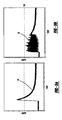
- the graph illustrates the in-rush current developed due to activation of the air pump when it is initially activated at the engine's cold start condition until full flow is achieved.
- a Line 54 depicts the unfavorable condition of the in-rush current exceeding 150 amps, and the pulse width modulated controller is not in use.
- Line 56 depicts the in-rush current controlled to less than or equal to 150 amps, when the pulse width modulated controller is used to apply a pulse width modulated voltage to the actuator of the secondary air supply device.
- the in-rush current can be controlled to be less than or equal to 150 amps.
- the actuator is initially energize, however, the specific amperes can vary depending on the needs of a particular application.
Description
- This application is a PCT International Application which claims the benefit of
U.S. Provisional Application No. 60/920, 161, filed March 27, 2007 - The present invention relates to a current limiting arrangement for a vehicle secondary air supply system.
- When an engine goes through a cold start condition a secondary air supply device can be used to inject air into the engine's exhaust manifold. This allows oxygen to be introduced to the exhaust and cause excess hydrocarbons to be combusted. This also helps the catalytic converter achieve optimal temperature in a shorter amount of time.
- Using secondary air supply devices can cause electric current surges into an actuator of an air pump when the actuator is initially energized from the cold start condition. This power surge is known as in-rush current. A surge of in-rush current into the actuator can cause undesirable conditions in the vehicle electrical system. Therefore, it is desirable to develop a current limiting arrangement wherein the actuator of the secondary air supply device is operably connected to a pulse width modulated controller to control the in-rush current.
-
US 5,456,063 discloses an apparatus for supplying the secondary air to a catalyst in an exhaust gas passage is disclosed. An electric heater is fixed to the catalyst to which the secondary air is supplied by an electric air pump. The heater and the air pump are connected with a battery through relay contacts, respectively. During the cold operation of the engine, an electric control unit switches on/off the relay contacts, so as to actuate the air pump prior to the heater and stop the air pump after the heater. The secondary air is supplied to the catalyst when the temperature of catalyst is raised up to the activating point.US 5,456,063 discloses an arrangement according to the preamble part ofclaim 1. -
JP 7150930 A - Arrangements according to the present invention are disclosed in the independent claims. The dependent claims contain further preferred developments of the invention. The present invention relates to a secondary air supply arrangement having an actuator operably connected to an air pump for creating air flow between an inlet and outlet of the air pump. A pulse width modulated controller is operably connected to the actuator for applying a pulse width modulated voltage to the actuator. The pulse width modulated controller controls the initial in-rush electric current when the actuator is activated.
- Further areas of applicability of the present invention will become apparent from the detailed description provided hereinafter. It should be understood that the detailed description and specific examples, while indicating the preferred embodiment of the invention, are intended for purposes of illustration only and are not intended to limit the scope of the invention.
- The present invention will become more fully understood from the detailed description and the accompanying drawings, wherein:
-
Figure 1 is a perspective view of the secondary air supply arrangement having the pulse width modulated controller connected remotely; -
Figure 2 is a perspective view of the secondary air supply arrangement having the pulse width modulated controller mounted to the air pump; -
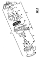
Figure 3 is an exploded view of the secondary air supply arrangement having the pulse width modulated controller integrated within the actuator; -
Figure 4 is a schematic diagram showing a current limiting arrangement; -
Figure 5a is a line graph illustrating the implications of in-rush current when no pulse width modulation is applied; and -
Figure 5b is a line graph showing the current controlled when the actuator of the secondary air supply arrangement is operably connected to the pulse width modulated controller. - The following description of the preferred embodiment(s) is merely exemplary in nature and is in no way intended to limit the invention, its application, or uses.
- Referring generally to
Figures 1-4 a secondary air supply arrangement is generally shown at 10 wherein the actuator generally shown at 12 receives electric current and is operably connected to the air pump generally shown at 14. Theactuator 12 is covered by acasing 16 that is connected to ahousing 18 of theair pump 14. Theair pump 14 has aninlet 20 and anoutlet 22 in which the air flows in and out of theair pump 14 respectfully. - The
actuator 12 energizes theair pump 14 causing animpeller 24 to rotate and cause air to flow through theinlet 20 andoutlet 22. It is understood, however, that a pumping fan or other mechanism can be used as an alternative to theimpeller 24. - The pulse width modulated
controller 26 is connected to abattery 28 and receives energy from thebattery 28. It is understood, however, that any conventional energy source can be used. The pulse width modulatedcontroller 26 is operably connected to theactuator 12 and controls the amount of voltage applied to theactuator 12. The air flow generated by theair pump 14 corresponds with the amount of voltage applied to theactuator 12 by the pulse width modulatedcontroller 26. The in-rush current experienced by theactuator 12 can be controlled to be less than or equal to 150 amps. when theactuator 12 is initially activated. However, the current range can vary depending on the needs of a particular application. - A
pump relay 30 is coupled to or integrated with the pulse width modulatedcontroller 26 and operably connected to theactuator 12. Thepump relay 30 receives a signal from anelectronic control unit 32 and acts as an on/off switch for allowing the application of voltage and flow of current to theactuator 12. However, it is not necessary for thepump relay 30 to be present for the pulse width modulatedcontroller 26 to control the amount of voltage applied to theactuator 12. - A
valve 34, as shown inFigure 4 , is operably connected to theoutlet 22 of theair pump 14 for controlling the flow of air to the engine'sexhaust manifold 36. Avalve relay 38 is operably connected to thevalve 34 and acts as an on/off switch to energize thevalve 34. Thevalve relay 38 can be coupled to the pulse width modulatedcontroller 26 and thepump relay 30, generally shown at 40, however, thevalve relay 38 controls the activation of thevalve 34. - Referring to
Figure 1 , one secondaryair supply arrangement 10 includes the pulse width modulatedcontroller 26 located remotely from a secondaryair supply device 42. Electric current from thebattery 28 flows through a connection to the pulse width modulatedcontroller 26. The pulse width modulatedcontroller 26 applies a pulse width modulated voltage to theactuator 12 either through thepump relay 30 or directly. Theactuator 12 energizes theair pump 14 causing air to flow through theinlet 20 andoutlet 22 respectfully. - The pulse width modulated
controller 26 and thepump relay 30 can alternatively be coupled to or integrated with theelectronic control unit 32 located remotely from the secondaryair supply device 42. The pulse width modulatedcontroller 26 applies a pulse width modulated voltage to theactuator 12 either through thepump relay 30 or directly. - Referring to
Figure 2 , an alternative secondaryair supply arrangement 10 includes the pulse width modulatedcontroller 26 as a solid state device connected on a top of acover 46 of theair pump 14. However, it is understood that the pulse width modulatedcontroller 26 can be connected anywhere on the outside of the secondaryair supply arrangement 10. Electric current from thebattery 28 flows through a connection to the pulse width modulatedcontroller 26. The pulse width modulatedcontroller 26 applies a pulse width modulated voltage to theactuator 12 either through thepump relay 30 or directly. - Referring to
Figure 3 , yet another alternative of the secondaryair supply arrangement 10 is shown, wherein the pulse width modulatedcontroller 26 is coupled to or integrated with theactuator 12. However, it is understood that the pulse width modulatedcontroller 26 can be integrated anywhere within the secondaryair supply device 42. Theactuator 12 is operably connected to theair pump 14 for creating air flow between theinlet 20 andoutlet 22 of theair pump 14. Thehousing 18 of theair pump 14 houses theimpeller 24 and includes anelectrical port 48. Alower flow chamber 50, having theoutlet 22, is connected to thehousing 18 and houses aparticulate filter 52. Thecover 46, having theinlet 20, is connected to thelower flow chamber 50. Air flows in and out of theinlet 20 and theoutlet 22 of theair pump 14 respectfully. - The battery delivers electric current through the
electrical port 48 to the pulse width modulatedcontroller 26. The pulse width modulatedcontroller 26 is operably connected to theactuator 12 and directly controls the voltage applied to theactuator 12. However, it is understood that the pump relay can be coupled to or integrated with the pulse width modulatedcontroller 26, wherein the pulse width modulatedcontroller 26 applies a pulse width modulated voltage to theactuator 12 through the pump relay. - Referring to
Figure 4 , a schematic diagram of a secondaryair supply arrangement 10 having thevalve relay 38 is shown. Electric current commanded by theelectronic control unit 32 flows through the connection to thepump relay 30 that is coupled to or integrated with the pulse width modulatedcontroller 26. The pulse width modulatedcontroller 26 applies a pulse width modulated voltage to the actuator generally shown at 12 either through thepump relay 30 or directly. Theactuator 12 energizes the air pump generally shown at 14 causing the impeller to rotate and cause air to flow through theinlet 20 and theoutlet 22 respectfully. Avalve relay 38 is operably connected to thevalve 34 and acts as an on/off switch to energize thevalve 34 and control the air flow to the engine'sexhaust manifold 36. Thevalve relay 38 can be coupled to the pulse width modulatedcontroller 26 and thepump relay 30, generally shown at 40, however, thevalve relay 38 controls the activation of thevalve 34. - Referring to
Figure 5a , the graph illustrates the in-rush current developed due to activation of the air pump when it is initially activated at the engine's cold start condition until full flow is achieved. ALine 54 depicts the unfavorable condition of the in-rush current exceeding 150 amps, and the pulse width modulated controller is not in use. - Referring to
Figure 5b ,Line 56 depicts the in-rush current controlled to less than or equal to 150 amps, when the pulse width modulated controller is used to apply a pulse width modulated voltage to the actuator of the secondary air supply device. The in-rush current can be controlled to be less than or equal to 150 amps. When the actuator is initially energize, however, the specific amperes can vary depending on the needs of a particular application.
Claims (17)
- A secondary air supply arrangement (10) comprising:an air pump (14) operable to create air flow between an inlet (20) and an outlet (22) of said air pump; andan actuator (12) operable to energize said air pump; a pulse width modulated controller (26) operably connected to said actuator for applying a pulse width modulated voltage to said actuator, wherein an initial in-rush electric current is controlled when said actuator is activated,
characterized bya valve (34) operably connected to said outlet of said air pump;a valve relay (38) coupled to said pulse width modulated controller and said pump relay, wherein said valve relay controls the activation of said valve. - The secondary air supply arrangement of claim 1 wherein said pulse width modulated controller is mounted to said air pump.
- The secondary air supply arrangement of claim 1 further comprising a pump relay (30) coupled to said pulse width modulated controller, wherein said pump relay switches a voltage to said actuator.
- The secondary air supply arrangement of claim 1 wherein said pulse width modulated controller is a solid state device.
- The secondary air supply arrangement of claim 1 wherein said in-rush electric current is preferably limited to less than or equal to 150 amps.
- The secondary air supply arrangement of claim 1 wherein voltage applied by said pulse width modulated controller is commanded by an electronic control unit (32).
- A current limiting arrangement comprising;an electronic control unit (32);a pump relay (30) connected to said electronic control unit;a pulse width modulated controller (26) connected to said pump relay;wherein an initial in-rush electric current is controlled when said actuator is activated;a battery (28) connected to said pulse width modulated controller;an air pump (14), wherein said air pump is energized by an actuator (12);a valve relay (38) coupled to said pump relay and said pulse width modulator controller; anda valve (34) operably connected to said valve relay.
- The current limiting arrangement of claim 7 wherein said pulse width modulated controller is a solid state device.
- The current limiting arrangement of claim 7 wherein said pulse width modulated controller is mounted to a top of said air pump.
- The current limiting arrangement of claim 7 wherein said pulse width modulated controller is integrated into said actuator.
- The current limiting arrangement of claim 7 wherein said pulse width modulated controller applies a pulse width modulated voltage to said actuator.
- The current limiting arrangement of claim 7 wherein said in-rush electric current is preferably limited to less than or equal to 150 amps.
- The current limiting arrangement of claim 7 wherein said valve relay variably controls a position of said valve.
- A secondary air supply arrangement comprising;an air pump (14) operable to create air flow between an inlet (20) and an outlet (22) of said air pump;an actuator (12) operable to energize said air pump;a pulse width modulated controller (26) operably connected to said actuator for applying a pulse width modulated voltage to said actuator, said pulse width modulated controller being a solid state device, wherein an initial in-rush electric current is controlled when said actuator is activated;a pump relay (30) operably connected to said pulse width modulated controller,wherein an electronic control unit (32) commands said pump relay and said pump relay switches electric flow to said actuator;a valve (34) operably connected to said outlet of said air pump for controlling the flow of air to an engine's exhaust manifold ; anda valve relay (38) coupled to said pulse width modulated controller and said pump relay, wherein said valve relay controls the activation of said valve.
- The secondary air supply arrangement of claim 14 wherein said pulse width modulated controller is coupled to or integrated with said actuator.
- The secondary air supply arrangement of claim 14 wherein said pulse width modulated controller is coupled to or integrated with said air pump.
- The secondary air supply arrangement of claim 14 wherein said in-rush electric current is preferably limited to less than or equal to 150 amps.
Applications Claiming Priority (2)
| Application Number | Priority Date | Filing Date | Title |
|---|---|---|---|
| US92016107P | 2007-03-27 | 2007-03-27 | |
| PCT/US2008/004040 WO2008118492A1 (en) | 2007-03-27 | 2008-03-27 | Current limiting driver for electric air pump |
Publications (3)
| Publication Number | Publication Date |
|---|---|
| EP2126303A1 EP2126303A1 (en) | 2009-12-02 |
| EP2126303A4 EP2126303A4 (en) | 2011-06-15 |
| EP2126303B1 true EP2126303B1 (en) | 2012-12-05 |
Family
ID=39788871
Family Applications (1)
| Application Number | Title | Priority Date | Filing Date |
|---|---|---|---|
| EP08742337A Not-in-force EP2126303B1 (en) | 2007-03-27 | 2008-03-27 | Current limiting driver for electric air pump |
Country Status (6)
| Country | Link |
|---|---|
| US (1) | US20100115929A1 (en) |
| EP (1) | EP2126303B1 (en) |
| JP (1) | JP2010522844A (en) |
| KR (1) | KR20090128477A (en) |
| CN (1) | CN101605970A (en) |
| WO (1) | WO2008118492A1 (en) |
Families Citing this family (2)
| Publication number | Priority date | Publication date | Assignee | Title |
|---|---|---|---|---|
| CN106466082A (en) * | 2015-08-16 | 2017-03-01 | 王春秋 | A kind of electric bed warmer |
| CN106286393A (en) * | 2016-09-01 | 2017-01-04 | 温州市彼得汽车部件有限公司 | A kind of automobile secondary air pump by exhaust gas drive |
Family Cites Families (17)
| Publication number | Priority date | Publication date | Assignee | Title |
|---|---|---|---|---|
| US2925253A (en) * | 1958-12-08 | 1960-02-16 | Long Company | Remote control unit for hydraulically operated tools |
| US4743816A (en) * | 1987-03-31 | 1988-05-10 | Westinghouse Electric Corp. | Microprocessor based motor protective relay with transition control |
| US5151017A (en) * | 1991-05-15 | 1992-09-29 | Itt Corporation | Variable speed hydromassage pump control |
| JP2988200B2 (en) * | 1992-07-10 | 1999-12-06 | トヨタ自動車株式会社 | Secondary air supply control device for electrically heated catalyst |
| JP2857307B2 (en) * | 1993-12-02 | 1999-02-17 | 株式会社デンソー | Diesel engine exhaust purification system |
| KR100245853B1 (en) * | 1995-12-27 | 2000-04-01 | 정몽규 | Idle speed actuator control method when secondary air supply system is activated |
| JP3301712B2 (en) * | 1997-03-14 | 2002-07-15 | 株式会社豊田自動織機 | Exhaust gas purification device for diesel engines for vehicles |
| US6265786B1 (en) * | 1998-01-05 | 2001-07-24 | Capstone Turbine Corporation | Turbogenerator power control system |
| JP2004257360A (en) * | 2003-02-27 | 2004-09-16 | Denso Corp | Secondary air supply system |
| JP4415779B2 (en) * | 2004-03-25 | 2010-02-17 | 株式会社デンソー | Drive device for secondary air introduction system |
| JP2005291150A (en) * | 2004-04-02 | 2005-10-20 | Denso Corp | Self-pressure opening and closing type pump device |
| US7207183B2 (en) * | 2004-04-12 | 2007-04-24 | York International Corp. | System and method for capacity control in a multiple compressor chiller system |
| US7413413B2 (en) * | 2004-07-20 | 2008-08-19 | York International Corporation | System and method to reduce acoustic noise in screw compressors |
| US7481627B2 (en) * | 2004-08-30 | 2009-01-27 | Mat Industries Llc | Air compressor tools that communicate with an air compressor |
| JP2006348812A (en) * | 2005-06-15 | 2006-12-28 | Hitachi Ltd | Secondary air supply device for internal combustion engine |
| JP2008114698A (en) * | 2006-11-02 | 2008-05-22 | Denso Corp | Electric pump control device, and internal combustion engine system using the same |
| TWI334764B (en) * | 2006-12-01 | 2010-12-11 | Delta Electronics Inc | Fan system and starting method thereof |
-
2008
- 2008-03-27 US US12/532,653 patent/US20100115929A1/en not_active Abandoned
- 2008-03-27 KR KR1020097021253A patent/KR20090128477A/en not_active Application Discontinuation
- 2008-03-27 CN CNA2008800046775A patent/CN101605970A/en active Pending
- 2008-03-27 WO PCT/US2008/004040 patent/WO2008118492A1/en active Application Filing
- 2008-03-27 JP JP2010501003A patent/JP2010522844A/en active Pending
- 2008-03-27 EP EP08742337A patent/EP2126303B1/en not_active Not-in-force
Also Published As
| Publication number | Publication date |
|---|---|
| EP2126303A1 (en) | 2009-12-02 |
| KR20090128477A (en) | 2009-12-15 |
| JP2010522844A (en) | 2010-07-08 |
| CN101605970A (en) | 2009-12-16 |
| EP2126303A4 (en) | 2011-06-15 |
| US20100115929A1 (en) | 2010-05-13 |
| WO2008118492A1 (en) | 2008-10-02 |
Similar Documents
| Publication | Publication Date | Title |
|---|---|---|
| EP2182190A2 (en) | Reactant delivery for engine exhaust gas treatment | |
| US8966883B2 (en) | Process for starting an SCR system | |
| US20080245343A1 (en) | Method For Operating a Fuel Pump | |
| JPH06207566A (en) | Built-in type electrically-driven fuel pump having outlet pressure adjusting function | |
| CN1329641C (en) | Secondary air supply system | |
| CN103282609A (en) | System and method for active regeneration of a dpf of a construction machine having an electro-ydraulic pump | |
| US10047658B2 (en) | Exhaust gas temperature control apparatus and exhaust gas temperature adjustment apparatus | |
| EP2126303B1 (en) | Current limiting driver for electric air pump | |
| US5459998A (en) | Apparatus for introducing fresh air into exhaust pipe of internal combustion engine for purification of exhaust gas | |
| JP3883508B2 (en) | FUEL CELL SYSTEM IN VEHICLE HAVING INTERNAL COMBUSTION ENGINE AND METHOD OF OPERATING THE SAME | |
| JP2005291150A (en) | Self-pressure opening and closing type pump device | |
| US5732880A (en) | Heater for a vehicle powered by an internal-combustion engine | |
| EP3620625B1 (en) | Exhaust after treatment system | |
| JP2004116522A (en) | Circuit for pulse width modulation driving electromagnetic purge valve for venting tank of automobile | |
| JPH06261420A (en) | Hybrid electric automobile | |
| WO2003099604A3 (en) | Method for operating an electrically driven motor vehicle and device therefor | |
| JP2005240583A (en) | Energizing control device of electric heating catalyst | |
| CN211370563U (en) | Diesel engine tail gas emission control device, diesel engine and motor vehicle | |
| KR100443969B1 (en) | Auxiliary Heater Controlling Device of Diesel Automobiles | |
| JP2010522844A5 (en) | ||
| JPH07150930A (en) | Duty controller of electric motor and exhaust emission control device of diesel engine | |
| JP4541719B2 (en) | Vehicle power supply | |
| CN114856770A (en) | Temperature adjusting system, engine and temperature adjusting method | |
| JP2023174590A (en) | Hybrid air heater device for vehicle | |
| JPH02161128A (en) | Control device for turbo-charger |
Legal Events
| Date | Code | Title | Description |
|---|---|---|---|
| PUAI | Public reference made under article 153(3) epc to a published international application that has entered the european phase |
Free format text: ORIGINAL CODE: 0009012 |
|
| 17P | Request for examination filed |
Effective date: 20090917 |
|
| AK | Designated contracting states |
Kind code of ref document: A1 Designated state(s): AT BE BG CH CY CZ DE DK EE ES FI FR GB GR HR HU IE IS IT LI LT LU LV MC MT NL NO PL PT RO SE SI SK TR |
|
| DAX | Request for extension of the european patent (deleted) | ||
| A4 | Supplementary search report drawn up and despatched |
Effective date: 20110517 |
|
| 17Q | First examination report despatched |
Effective date: 20120314 |
|
| GRAP | Despatch of communication of intention to grant a patent |
Free format text: ORIGINAL CODE: EPIDOSNIGR1 |
|
| GRAS | Grant fee paid |
Free format text: ORIGINAL CODE: EPIDOSNIGR3 |
|
| GRAA | (expected) grant |
Free format text: ORIGINAL CODE: 0009210 |
|
| AK | Designated contracting states |
Kind code of ref document: B1 Designated state(s): AT BE BG CH CY CZ DE DK EE ES FI FR GB GR HR HU IE IS IT LI LT LU LV MC MT NL NO PL PT RO SE SI SK TR |
|
| REG | Reference to a national code |
Ref country code: GB Ref legal event code: FG4D |
|
| REG | Reference to a national code |
Ref country code: CH Ref legal event code: EP |
|
| REG | Reference to a national code |
Ref country code: AT Ref legal event code: REF Ref document number: 587420 Country of ref document: AT Kind code of ref document: T Effective date: 20121215 |
|
| REG | Reference to a national code |
Ref country code: IE Ref legal event code: FG4D |
|
| REG | Reference to a national code |
Ref country code: DE Ref legal event code: R096 Ref document number: 602008020613 Country of ref document: DE Effective date: 20130131 |
|
| REG | Reference to a national code |
Ref country code: AT Ref legal event code: MK05 Ref document number: 587420 Country of ref document: AT Kind code of ref document: T Effective date: 20121205 |
|
| PG25 | Lapsed in a contracting state [announced via postgrant information from national office to epo] |
Ref country code: HR Free format text: LAPSE BECAUSE OF FAILURE TO SUBMIT A TRANSLATION OF THE DESCRIPTION OR TO PAY THE FEE WITHIN THE PRESCRIBED TIME-LIMIT Effective date: 20121205 Ref country code: LT Free format text: LAPSE BECAUSE OF FAILURE TO SUBMIT A TRANSLATION OF THE DESCRIPTION OR TO PAY THE FEE WITHIN THE PRESCRIBED TIME-LIMIT Effective date: 20121205 Ref country code: ES Free format text: LAPSE BECAUSE OF FAILURE TO SUBMIT A TRANSLATION OF THE DESCRIPTION OR TO PAY THE FEE WITHIN THE PRESCRIBED TIME-LIMIT Effective date: 20130316 Ref country code: FI Free format text: LAPSE BECAUSE OF FAILURE TO SUBMIT A TRANSLATION OF THE DESCRIPTION OR TO PAY THE FEE WITHIN THE PRESCRIBED TIME-LIMIT Effective date: 20121205 Ref country code: NO Free format text: LAPSE BECAUSE OF FAILURE TO SUBMIT A TRANSLATION OF THE DESCRIPTION OR TO PAY THE FEE WITHIN THE PRESCRIBED TIME-LIMIT Effective date: 20130305 Ref country code: SE Free format text: LAPSE BECAUSE OF FAILURE TO SUBMIT A TRANSLATION OF THE DESCRIPTION OR TO PAY THE FEE WITHIN THE PRESCRIBED TIME-LIMIT Effective date: 20121205 |
|
| REG | Reference to a national code |
Ref country code: NL Ref legal event code: VDEP Effective date: 20121205 |
|
| REG | Reference to a national code |
Ref country code: LT Ref legal event code: MG4D |
|
| PG25 | Lapsed in a contracting state [announced via postgrant information from national office to epo] |
Ref country code: SI Free format text: LAPSE BECAUSE OF FAILURE TO SUBMIT A TRANSLATION OF THE DESCRIPTION OR TO PAY THE FEE WITHIN THE PRESCRIBED TIME-LIMIT Effective date: 20121205 Ref country code: LV Free format text: LAPSE BECAUSE OF FAILURE TO SUBMIT A TRANSLATION OF THE DESCRIPTION OR TO PAY THE FEE WITHIN THE PRESCRIBED TIME-LIMIT Effective date: 20121205 Ref country code: PL Free format text: LAPSE BECAUSE OF FAILURE TO SUBMIT A TRANSLATION OF THE DESCRIPTION OR TO PAY THE FEE WITHIN THE PRESCRIBED TIME-LIMIT Effective date: 20121205 Ref country code: GR Free format text: LAPSE BECAUSE OF FAILURE TO SUBMIT A TRANSLATION OF THE DESCRIPTION OR TO PAY THE FEE WITHIN THE PRESCRIBED TIME-LIMIT Effective date: 20130306 |
|
| PG25 | Lapsed in a contracting state [announced via postgrant information from national office to epo] |
Ref country code: AT Free format text: LAPSE BECAUSE OF FAILURE TO SUBMIT A TRANSLATION OF THE DESCRIPTION OR TO PAY THE FEE WITHIN THE PRESCRIBED TIME-LIMIT Effective date: 20121205 |
|
| PG25 | Lapsed in a contracting state [announced via postgrant information from national office to epo] |
Ref country code: IS Free format text: LAPSE BECAUSE OF FAILURE TO SUBMIT A TRANSLATION OF THE DESCRIPTION OR TO PAY THE FEE WITHIN THE PRESCRIBED TIME-LIMIT Effective date: 20130405 Ref country code: SK Free format text: LAPSE BECAUSE OF FAILURE TO SUBMIT A TRANSLATION OF THE DESCRIPTION OR TO PAY THE FEE WITHIN THE PRESCRIBED TIME-LIMIT Effective date: 20121205 Ref country code: CZ Free format text: LAPSE BECAUSE OF FAILURE TO SUBMIT A TRANSLATION OF THE DESCRIPTION OR TO PAY THE FEE WITHIN THE PRESCRIBED TIME-LIMIT Effective date: 20121205 Ref country code: BG Free format text: LAPSE BECAUSE OF FAILURE TO SUBMIT A TRANSLATION OF THE DESCRIPTION OR TO PAY THE FEE WITHIN THE PRESCRIBED TIME-LIMIT Effective date: 20130305 Ref country code: EE Free format text: LAPSE BECAUSE OF FAILURE TO SUBMIT A TRANSLATION OF THE DESCRIPTION OR TO PAY THE FEE WITHIN THE PRESCRIBED TIME-LIMIT Effective date: 20121205 Ref country code: BE Free format text: LAPSE BECAUSE OF FAILURE TO SUBMIT A TRANSLATION OF THE DESCRIPTION OR TO PAY THE FEE WITHIN THE PRESCRIBED TIME-LIMIT Effective date: 20121205 |
|
| PG25 | Lapsed in a contracting state [announced via postgrant information from national office to epo] |
Ref country code: PT Free format text: LAPSE BECAUSE OF FAILURE TO SUBMIT A TRANSLATION OF THE DESCRIPTION OR TO PAY THE FEE WITHIN THE PRESCRIBED TIME-LIMIT Effective date: 20130405 Ref country code: RO Free format text: LAPSE BECAUSE OF FAILURE TO SUBMIT A TRANSLATION OF THE DESCRIPTION OR TO PAY THE FEE WITHIN THE PRESCRIBED TIME-LIMIT Effective date: 20121205 Ref country code: NL Free format text: LAPSE BECAUSE OF FAILURE TO SUBMIT A TRANSLATION OF THE DESCRIPTION OR TO PAY THE FEE WITHIN THE PRESCRIBED TIME-LIMIT Effective date: 20121205 |
|
| PLBE | No opposition filed within time limit |
Free format text: ORIGINAL CODE: 0009261 |
|
| STAA | Information on the status of an ep patent application or granted ep patent |
Free format text: STATUS: NO OPPOSITION FILED WITHIN TIME LIMIT |
|
| PG25 | Lapsed in a contracting state [announced via postgrant information from national office to epo] |
Ref country code: DK Free format text: LAPSE BECAUSE OF FAILURE TO SUBMIT A TRANSLATION OF THE DESCRIPTION OR TO PAY THE FEE WITHIN THE PRESCRIBED TIME-LIMIT Effective date: 20121205 Ref country code: MC Free format text: LAPSE BECAUSE OF NON-PAYMENT OF DUE FEES Effective date: 20130331 |
|
| REG | Reference to a national code |
Ref country code: CH Ref legal event code: PL |
|
| 26N | No opposition filed |
Effective date: 20130906 |
|
| PG25 | Lapsed in a contracting state [announced via postgrant information from national office to epo] |
Ref country code: CY Free format text: LAPSE BECAUSE OF FAILURE TO SUBMIT A TRANSLATION OF THE DESCRIPTION OR TO PAY THE FEE WITHIN THE PRESCRIBED TIME-LIMIT Effective date: 20121205 |
|
| REG | Reference to a national code |
Ref country code: IE Ref legal event code: MM4A |
|
| REG | Reference to a national code |
Ref country code: DE Ref legal event code: R097 Ref document number: 602008020613 Country of ref document: DE Effective date: 20130906 |
|
| PG25 | Lapsed in a contracting state [announced via postgrant information from national office to epo] |
Ref country code: CH Free format text: LAPSE BECAUSE OF NON-PAYMENT OF DUE FEES Effective date: 20130331 Ref country code: IE Free format text: LAPSE BECAUSE OF NON-PAYMENT OF DUE FEES Effective date: 20130327 Ref country code: LI Free format text: LAPSE BECAUSE OF NON-PAYMENT OF DUE FEES Effective date: 20130331 |
|
| PG25 | Lapsed in a contracting state [announced via postgrant information from national office to epo] |
Ref country code: MT Free format text: LAPSE BECAUSE OF FAILURE TO SUBMIT A TRANSLATION OF THE DESCRIPTION OR TO PAY THE FEE WITHIN THE PRESCRIBED TIME-LIMIT Effective date: 20121205 |
|
| REG | Reference to a national code |
Ref country code: FR Ref legal event code: PLFP Year of fee payment: 8 |
|
| PGFP | Annual fee paid to national office [announced via postgrant information from national office to epo] |
Ref country code: IT Payment date: 20150325 Year of fee payment: 8 |
|
| PGFP | Annual fee paid to national office [announced via postgrant information from national office to epo] |
Ref country code: FR Payment date: 20150224 Year of fee payment: 8 Ref country code: GB Payment date: 20150224 Year of fee payment: 8 |
|
| PG25 | Lapsed in a contracting state [announced via postgrant information from national office to epo] |
Ref country code: TR Free format text: LAPSE BECAUSE OF FAILURE TO SUBMIT A TRANSLATION OF THE DESCRIPTION OR TO PAY THE FEE WITHIN THE PRESCRIBED TIME-LIMIT Effective date: 20121205 |
|
| PG25 | Lapsed in a contracting state [announced via postgrant information from national office to epo] |
Ref country code: HU Free format text: LAPSE BECAUSE OF FAILURE TO SUBMIT A TRANSLATION OF THE DESCRIPTION OR TO PAY THE FEE WITHIN THE PRESCRIBED TIME-LIMIT; INVALID AB INITIO Effective date: 20080327 Ref country code: LU Free format text: LAPSE BECAUSE OF NON-PAYMENT OF DUE FEES Effective date: 20130327 |
|
| PGFP | Annual fee paid to national office [announced via postgrant information from national office to epo] |
Ref country code: DE Payment date: 20150331 Year of fee payment: 8 |
|
| REG | Reference to a national code |
Ref country code: DE Ref legal event code: R119 Ref document number: 602008020613 Country of ref document: DE |
|
| GBPC | Gb: european patent ceased through non-payment of renewal fee |
Effective date: 20160327 |
|
| REG | Reference to a national code |
Ref country code: FR Ref legal event code: ST Effective date: 20161130 |
|
| PG25 | Lapsed in a contracting state [announced via postgrant information from national office to epo] |
Ref country code: GB Free format text: LAPSE BECAUSE OF NON-PAYMENT OF DUE FEES Effective date: 20160327 Ref country code: DE Free format text: LAPSE BECAUSE OF NON-PAYMENT OF DUE FEES Effective date: 20161001 Ref country code: FR Free format text: LAPSE BECAUSE OF NON-PAYMENT OF DUE FEES Effective date: 20160331 |
|
| PG25 | Lapsed in a contracting state [announced via postgrant information from national office to epo] |
Ref country code: IT Free format text: LAPSE BECAUSE OF NON-PAYMENT OF DUE FEES Effective date: 20160327 |