EP2126298B1 - Dispositif de dosage d'agent de réduction - Google Patents
Dispositif de dosage d'agent de réduction Download PDFInfo
- Publication number
- EP2126298B1 EP2126298B1 EP07847180A EP07847180A EP2126298B1 EP 2126298 B1 EP2126298 B1 EP 2126298B1 EP 07847180 A EP07847180 A EP 07847180A EP 07847180 A EP07847180 A EP 07847180A EP 2126298 B1 EP2126298 B1 EP 2126298B1
- Authority
- EP
- European Patent Office
- Prior art keywords
- line
- working
- tank
- store
- reducing agent
- Prior art date
- Legal status (The legal status is an assumption and is not a legal conclusion. Google has not performed a legal analysis and makes no representation as to the accuracy of the status listed.)
- Active
Links
Images
Classifications
-
- F—MECHANICAL ENGINEERING; LIGHTING; HEATING; WEAPONS; BLASTING
- F01—MACHINES OR ENGINES IN GENERAL; ENGINE PLANTS IN GENERAL; STEAM ENGINES
- F01N—GAS-FLOW SILENCERS OR EXHAUST APPARATUS FOR MACHINES OR ENGINES IN GENERAL; GAS-FLOW SILENCERS OR EXHAUST APPARATUS FOR INTERNAL COMBUSTION ENGINES
- F01N3/00—Exhaust or silencing apparatus having means for purifying, rendering innocuous, or otherwise treating exhaust
- F01N3/08—Exhaust or silencing apparatus having means for purifying, rendering innocuous, or otherwise treating exhaust for rendering innocuous
- F01N3/10—Exhaust or silencing apparatus having means for purifying, rendering innocuous, or otherwise treating exhaust for rendering innocuous by thermal or catalytic conversion of noxious components of exhaust
- F01N3/18—Exhaust or silencing apparatus having means for purifying, rendering innocuous, or otherwise treating exhaust for rendering innocuous by thermal or catalytic conversion of noxious components of exhaust characterised by methods of operation; Control
- F01N3/20—Exhaust or silencing apparatus having means for purifying, rendering innocuous, or otherwise treating exhaust for rendering innocuous by thermal or catalytic conversion of noxious components of exhaust characterised by methods of operation; Control specially adapted for catalytic conversion ; Methods of operation or control of catalytic converters
- F01N3/2066—Selective catalytic reduction [SCR]
-
- F—MECHANICAL ENGINEERING; LIGHTING; HEATING; WEAPONS; BLASTING
- F01—MACHINES OR ENGINES IN GENERAL; ENGINE PLANTS IN GENERAL; STEAM ENGINES
- F01N—GAS-FLOW SILENCERS OR EXHAUST APPARATUS FOR MACHINES OR ENGINES IN GENERAL; GAS-FLOW SILENCERS OR EXHAUST APPARATUS FOR INTERNAL COMBUSTION ENGINES
- F01N2610/00—Adding substances to exhaust gases
- F01N2610/02—Adding substances to exhaust gases the substance being ammonia or urea
-
- F—MECHANICAL ENGINEERING; LIGHTING; HEATING; WEAPONS; BLASTING
- F01—MACHINES OR ENGINES IN GENERAL; ENGINE PLANTS IN GENERAL; STEAM ENGINES
- F01N—GAS-FLOW SILENCERS OR EXHAUST APPARATUS FOR MACHINES OR ENGINES IN GENERAL; GAS-FLOW SILENCERS OR EXHAUST APPARATUS FOR INTERNAL COMBUSTION ENGINES
- F01N2610/00—Adding substances to exhaust gases
- F01N2610/10—Adding substances to exhaust gases the substance being heated, e.g. by heating tank or supply line of the added substance
-
- F—MECHANICAL ENGINEERING; LIGHTING; HEATING; WEAPONS; BLASTING
- F01—MACHINES OR ENGINES IN GENERAL; ENGINE PLANTS IN GENERAL; STEAM ENGINES
- F01N—GAS-FLOW SILENCERS OR EXHAUST APPARATUS FOR MACHINES OR ENGINES IN GENERAL; GAS-FLOW SILENCERS OR EXHAUST APPARATUS FOR INTERNAL COMBUSTION ENGINES
- F01N2610/00—Adding substances to exhaust gases
- F01N2610/14—Arrangements for the supply of substances, e.g. conduits
- F01N2610/1406—Storage means for substances, e.g. tanks or reservoirs
-
- F—MECHANICAL ENGINEERING; LIGHTING; HEATING; WEAPONS; BLASTING
- F01—MACHINES OR ENGINES IN GENERAL; ENGINE PLANTS IN GENERAL; STEAM ENGINES
- F01N—GAS-FLOW SILENCERS OR EXHAUST APPARATUS FOR MACHINES OR ENGINES IN GENERAL; GAS-FLOW SILENCERS OR EXHAUST APPARATUS FOR INTERNAL COMBUSTION ENGINES
- F01N2610/00—Adding substances to exhaust gases
- F01N2610/14—Arrangements for the supply of substances, e.g. conduits
- F01N2610/1473—Overflow or return means for the substances, e.g. conduits or valves for the return path
-
- Y—GENERAL TAGGING OF NEW TECHNOLOGICAL DEVELOPMENTS; GENERAL TAGGING OF CROSS-SECTIONAL TECHNOLOGIES SPANNING OVER SEVERAL SECTIONS OF THE IPC; TECHNICAL SUBJECTS COVERED BY FORMER USPC CROSS-REFERENCE ART COLLECTIONS [XRACs] AND DIGESTS
- Y02—TECHNOLOGIES OR APPLICATIONS FOR MITIGATION OR ADAPTATION AGAINST CLIMATE CHANGE
- Y02A—TECHNOLOGIES FOR ADAPTATION TO CLIMATE CHANGE
- Y02A50/00—TECHNOLOGIES FOR ADAPTATION TO CLIMATE CHANGE in human health protection, e.g. against extreme weather
- Y02A50/20—Air quality improvement or preservation, e.g. vehicle emission control or emission reduction by using catalytic converters
-
- Y—GENERAL TAGGING OF NEW TECHNOLOGICAL DEVELOPMENTS; GENERAL TAGGING OF CROSS-SECTIONAL TECHNOLOGIES SPANNING OVER SEVERAL SECTIONS OF THE IPC; TECHNICAL SUBJECTS COVERED BY FORMER USPC CROSS-REFERENCE ART COLLECTIONS [XRACs] AND DIGESTS
- Y02—TECHNOLOGIES OR APPLICATIONS FOR MITIGATION OR ADAPTATION AGAINST CLIMATE CHANGE
- Y02T—CLIMATE CHANGE MITIGATION TECHNOLOGIES RELATED TO TRANSPORTATION
- Y02T10/00—Road transport of goods or passengers
- Y02T10/10—Internal combustion engine [ICE] based vehicles
- Y02T10/12—Improving ICE efficiencies
Definitions
- the invention relates to a device for dosing a liquid reducing agent in an exhaust system, which can be used in particular for the reduction of nitrogen oxides in an exhaust gas of a motor vehicle.
- a selective catalytic reduction is carried out in which the nitrogen oxides are reduced to nitrogen and water by means of reducing agents.
- reducing agent for example, an aqueous urea solution is used.
- the reducing agent is usually stored in a tank and conveyed via a line from the tank to a dosing module, with which the reducing agent is injected, for example, into the exhaust pipe.
- the system usually operates with a predetermined system pressure, which is realized for example via the speed of a pump motor and corresponding sensor systems and chokes.
- a challenge in known two-tank systems is the management of the reducing agent distribution to the two tanks. First, it must be ensured that the heated working tank is always supplied with a sufficient amount of liquid reducing agent to the motor vehicle even during an unforeseen cold period with sufficient supply liquid reducing agent.
- an apparatus for metering a liquid reducing agent into an exhaust system is proposed, in particular for reducing nitrogen oxides in an exhaust gas, which avoids the disadvantages of known devices and over known devices, such as the EP 0 928 884 A2 , Advantageously developed.
- the device can be used, for example, in the context of the SCR methods described above, for example, to inject urea-water solutions or other liquid or liquid / gaseous reducing agents or suspensions or emulsions of reducing agents in an exhaust system.
- the device according to the invention comprises at least one working container for storing a working amount of the liquid reducing agent and at least one storage container for storing a quantity of the fluid exceeding the working quantity Reducing agent.
- the invention particularly relates to the communication between storage container and work container. This communication is realized via a feed pump, which can be dispensed with an additional shut-off valve or an additional pump for pumping. The pumping process can take place in particular during the journey of a motor vehicle, that is to say in particular during the metering operation.
- the device according to the invention is characterized by a simple system structure, which can be realized cost-effectively.
- a complex control unit which may nonetheless nevertheless be provided
- the functionality of the control unit in particular the requirements for software and resource requirements
- the proposed device in particular due to its simple design, as part of a fault diagnosis, especially in the context of an on-board diagnostic system (OBD), easy to monitor.
- OBD on-board diagnostic system
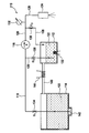
- FIG. 1 shows an embodiment of a device according to the invention, comprising a storage container, a working container, a feed pump and a metering module.
- FIG. 1 a preferred embodiment of a device 110 according to the invention for metering a liquid reducing agent is shown in an exhaust system.
- This device 110 can be used, for example, in the context of the applications described at the outset known from the prior art for reducing pollutants in the exhaust gas, in particular for reducing nitrogen oxides.
- the device according to the invention comprises in this embodiment a working container 112 and a storage container 114.
- a working container 112 instead of one container in each case, embodiments with a plurality of containers are possible, for example in the context of systems, which are based on a separate storage of various substances, which are then mixed before dosing.
- the device 110 comprises a feed pump 116, which (preferably simultaneously) can suck in liquid reducing agent 122 from the storage container 114 via a bearing suction line 118 and from the working container 112 via a working suction line 120.
- a feed pump 116 which (preferably simultaneously) can suck in liquid reducing agent 122 from the storage container 114 via a bearing suction line 118 and from the working container 112 via a working suction line 120.
- it may be an aqueous urea solution which can be used, for example, to reduce the pollutant NOx in a catalyst to N 2 and H 2 O.
- diaphragm pumps have proven to be suitable as a delivery pump 116, although other pump systems can also be used.
- the feed pump 116 is connected on its pressure side via a metering line 126 with a metering module 124, which may be arranged for example in the exhaust gas tract of an internal combustion engine.
- a metering module 124 which may be arranged for example in the exhaust gas tract of an internal combustion engine.
- metering modules which may be, for example, injectors
- a branching from the dosing 126 return line 128 is provided, which opens into the working container 112.
- the pressure in the dosing line 126 may be monitored with one or more pressure sensors 130.
- one of these pressure sensors 130 is arranged between the branch of the return line 128 and the dosing module 124.
- the pressure sensor 130 may, for example, be connected to the feed pump 116 via a simple control, for example in order to regulate a rotational speed of this feed pump 116 and thus to adjust the delivery rate or the pressure in the metering line 126.
- a simple control for example in order to regulate a rotational speed of this feed pump 116 and thus to adjust the delivery rate or the pressure in the metering line 126.
- Even more complex control systems are feasible, which may include, for example, electronic control devices, such as microcomputers.
- the working container 112 is dimensioned from its maximum capacity forth so that it can advantageously provide sufficient liquid reducing agent for the operation of the motor vehicle for a winter season.
- the maximum capacity is in the range between 1 and 15 l, especially in this way, in the cold season, the operation of the motor vehicle can be maintained only with the amount of liquid reducing agent 122 stored in the working container 112, so that only the working container 112 with a working container heater 132 (in FIG FIG. 1 only symbolically represented) should be equipped. On a heating of the storage container 114 can be omitted.
- each throttle elements 134, 136, 138 are arranged, which can be configured for example as throttle elements with a predetermined throttle area or as adjustable (eg adjustable) throttle elements and which in FIG. 1 are denoted by D 1 , D 2 and D 3, respectively.
- the feed pump 116 sucks during the (normal) operation both from the storage container 114 and from the working container 112 liquid reducing agent 122 at.
- the intake lines 118, 120 are matched to one another (for example, by corresponding embodiments of the throttle elements 134, 136) that from the storage container 114 always (corresponding levels in the containers 114, 112 assuming) a larger amount is removed than from the working container 112th
- the storage container 114 has a capacity which exceeds the maximum capacity of the working container 112.
- the maximum capacity of the storage container is in the range between 15 l and 100 l, in particular in the range between 20 l and 50 l.
- the working container 112 and the storage container 114 are connected to one another via one or more overflow lines 140, which is designed in particular as a simple hydraulic overflow line. Due to the coordination of the throttle elements 134, 136 and 138 relative to each other, the additional amount of liquid reducing agent 122 taken from the storage container 114 causes the working container 112 to be filled under normal conditions until the confluence of the overflow line 140 into this working container 112.
- this confluence of the overflow line 140 into the working container 112 may define the maximum level of the working container 112.
- fill level sensors for example in the working container 112 and / or in the storage container 114, be provided.
- the maximum filling quantity of the working container 112 in the illustrated embodiment is therefore independent of the filling level of the storage container 114.
- the maximum filling level in the working container 112 is determined by the axial position of the mouth of the overflow line 140.
- the two containers 112, 114 are preferably arranged relative to one another such that the maximum fill level of the storage container 114 (which can be monitored, for example, by corresponding sensors) is always below or equal to the fill level of the work container 112. This ensures that the amount of liquid reducing agent 122 flowing back into the working container 112 via the return line 128 can always flow back into the storage container 114 via the overflow line 140 and thus no overfilling of the working container 112 can occur. On corresponding sensors in the working container 112 could thus be dispensed with.
- the working container 112 in the metering operation (that is, for example, while driving) from the storage container 114 of Device 110 fed via the return line 128.
- the storage container 114 (which is unheated in this preferred embodiment) freezes, the dosing operation is only fed by the heated working container 112, since the bearing suction line 118 within the storage container 114 is likewise frozen and thus closed.
- the feed pump 116 compensates for this cross-sectional loss in the intake lines 118, 120, for example, regulated via the pressure sensor 130, preferably by an increased speed. If the storage container 114 is frozen, as a rule, the overflow line 140 also loses its function.
- the storage container 114 and in particular the suction point 142 of the Lageransaug réelle 118 in the storage container 114 is executed or insulated so that the suction point 142 freezes in time before the overflow pipe 140.
- the overflow line 140 should not thaw after the storage tank 114.
- This temporal sequence of the freezing or thawing processes can be designed, for example, by a corresponding configuration of the insulation of the storage container 114 in the region of the suction point 142.
- the overflow line 140 may be configured as completely or partially heated overflow line 140, for example by Use of overflow heater 144 (in FIG. 1 only indicated symbolically). These preferred embodiments ensure that overfilling of the working container 112 is avoided even when the device 110 freezes.
- the branch of the return line 128 from the metering line 126 is shown lying between the feed pump 116 and the metering module 124.
- this branch can also be designed differently.
- the branch can also be arranged within the dosing module 124 itself, ie be part of the dosing module 124.
- further return lines 128 may be provided, for example a leakage return line from the dosing module 124 into the working container 112.
Abstract
Claims (10)
- Dispositif (110) pour le dosage d'un agent de réduction fluide (122) dans un système de gaz d'échappement, notamment pour la réduction d'oxydes d'azote dans un gaz d'échappement, comprenant au moins un récipient de travail (112) pour fournir une quantité de travail de l'agent de réduction fluide (122), au moins un récipient de stockage (114) pour fournir une quantité de stockage de l'agent de réduction fluide (122) dépassant de préférence la quantité de travail, au moins un module de dosage (124) et au moins une pompe de refoulement (116), la pompe de refoulement (116) étant prévue pour aspirer de l'agent de réduction fluide (122) par le biais d'au moins une conduite d'aspiration de stockage (118) hors du récipient de stockage (114) et par le biais d'au moins une conduite d'aspiration de travail (120) hors du récipient de travail (112), et pour l'acheminer par le biais d'au moins une conduite de dosage (126) au module de dosage (124), la conduite de dosage (126) étant connectée par le biais d'au moins une conduite de retour (128) au récipient de travail (112), et le récipient de travail (112) étant connecté par le biais d'au moins une conduite de débordement (140) au récipient de stockage (114).
- Dispositif (110) selon la revendication précédente, caractérisé en ce que la conduite d'aspiration de stockage (118) et la conduite d'aspiration de travail (120) sont dimensionnées de telle sorte, en particulier en utilisant au moins un étranglement de stockage (134) disposé dans la conduite d'aspiration de stockage (118) et au moins un étranglement de travail (136) disposé dans la conduite d'aspiration de travail (120), que la quantité d'agent de réduction fluide (122) aspirée par la pompe de refoulement (116) hors du récipient de stockage (114) soit toujours supérieure, pendant le fonctionnement, à la quantité aspirée hors du récipient de travail (112).
- Dispositif (110) selon l'une quelconque des deux revendications précédentes, caractérisé par au moins un étranglement de retour (138) reçu dans la conduite de retour (128) pour ajuster une quantité d'agent de réduction fluide (122) ramenée hors de la conduite de dosage (126) dans le récipient de travail (112).
- Dispositif (110) selon l'une quelconque des revendications précédentes, caractérisé en ce que le récipient de stockage (114) et la conduite de débordement (140) sont conçus de telle sorte que même dans le cas d'un niveau de remplissage maximum du récipient de stockage (114), un débordement du récipient de travail (112) à travers la conduite de débordement (140) est rendu possible dans le récipient de stockage (114).
- Dispositif (110) selon l'une quelconque des revendications précédentes, caractérisé en ce que le niveau de remplissage maximum du récipient de stockage (114) est toujours en dessous ou égal au niveau de remplissage maximum du récipient de travail (112).
- Dispositif (110) selon l'une quelconque des revendications précédentes, caractérisé en ce que le récipient de travail (112) peut être chauffé complètement ou en partie.
- Dispositif (110) selon l'une quelconque des revendications précédentes, caractérisé en ce que le récipient de stockage (114) et la conduite de débordement (140) sont configurés de telle sorte que dans le cas d'une extraction de chaleur par diminution de la température, un point d'aspiration (142) de la conduite d'aspiration de stockage (118) dans le récipient de stockage (114) gèle en premier, suivi de la conduite de débordement (140), et en ce que dans le cas d'un apport de chaleur par augmentation de la température, la conduite de débordement (140) dégivre en premier, suivi du point d'aspiration (142) de la conduite d'aspiration de stockage (118) dans le récipient de stockage (114).
- Dispositif (110) selon l'une quelconque des revendications précédentes, caractérisé en ce que la conduite de débordement (140) peut être chauffée complètement ou en partie.
- Dispositif (110) selon l'une quelconque des revendications précédentes, caractérisé en ce que le récipient de travail (112) présente une contenance pour les besoins d'un fonctionnement d'un véhicule automobile pendant la saison d'hiver, en particulier une contenance de l'ordre de 1 à 15 litres, de préférence de l'ordre de 5 à 8 litres et particulièrement préférablement de 6 litres.
- Dispositif (110) selon l'une quelconque des revendications précédentes, caractérisé en ce que dans la conduite de dosage (126) est prévu au moins un capteur de pression (130) de préférence entre la dérivation de la conduite de retour (128) et le module de dosage (124).
Applications Claiming Priority (2)
| Application Number | Priority Date | Filing Date | Title |
|---|---|---|---|
| DE102006061734A DE102006061734A1 (de) | 2006-12-28 | 2006-12-28 | Vorrichtung zum Dosieren eines Reduktionsmittels |
| PCT/EP2007/062406 WO2008080689A1 (fr) | 2006-12-28 | 2007-11-15 | Dispositif de dosage d'agent de réduction |
Publications (2)
| Publication Number | Publication Date |
|---|---|
| EP2126298A1 EP2126298A1 (fr) | 2009-12-02 |
| EP2126298B1 true EP2126298B1 (fr) | 2010-03-10 |
Family
ID=38800863
Family Applications (1)
| Application Number | Title | Priority Date | Filing Date |
|---|---|---|---|
| EP07847180A Active EP2126298B1 (fr) | 2006-12-28 | 2007-11-15 | Dispositif de dosage d'agent de réduction |
Country Status (3)
| Country | Link |
|---|---|
| EP (1) | EP2126298B1 (fr) |
| DE (2) | DE102006061734A1 (fr) |
| WO (1) | WO2008080689A1 (fr) |
Families Citing this family (9)
| Publication number | Priority date | Publication date | Assignee | Title |
|---|---|---|---|---|
| FR2921911A1 (fr) | 2007-09-21 | 2009-04-10 | Inergy Automotive Systems Res | Systeme de stockage et d'injection d'une solution d'additif dans des gaz d'echappement d'un moteur. |
| DE102008034211A1 (de) * | 2008-07-23 | 2010-01-28 | Bayerische Motoren Werke Aktiengesellschaft | Reduktionsmittel-Tank für ein gefrierendes Reduktionsmittel |
| DE102010033754B4 (de) * | 2010-08-09 | 2018-01-18 | Siemens Aktiengesellschaft | Fluidspeichermanagementsystem und Verfahren zur Überwachung von Fluidkapazitäten und zur Steuerung der Übertragung von Fluidkapazitäten innerhalb eines Fluidnetzes |
| DE102010042461A1 (de) * | 2010-10-14 | 2011-09-29 | Robert Bosch Gmbh | Dosiersystem für eine Vorrichtung zur Nachbehandlung von Abgasen |
| DE102011075298A1 (de) * | 2011-05-05 | 2012-11-08 | Robert Bosch Gmbh | Pumpvorrichtung für Dosiersystem |
| DE102012218851A1 (de) * | 2012-10-16 | 2014-04-17 | Bosch Emission Systems Gmbh & Co. Kg | Reduktionsmittelzuführeinrichtung |
| US20170002710A1 (en) * | 2014-04-04 | 2017-01-05 | Harry Edward GORMAN | Anti-clogging device for diesel exhaust fluid supply |
| EP3324030A1 (fr) | 2016-11-17 | 2018-05-23 | Plastic Omnium Advanced Innovation and Research | Système de stockage d'une solution aqueuse à bord d'un véhicule |
| EP3324031A1 (fr) * | 2016-11-17 | 2018-05-23 | Plastic Omnium Advanced Innovation and Research | Système de stockage d'une solution aqueuse à bord d'un véhicule |
Family Cites Families (4)
| Publication number | Priority date | Publication date | Assignee | Title |
|---|---|---|---|---|
| DE8434979U1 (de) * | 1984-11-29 | 1985-02-28 | Hillmer, Helmut, 2050 Hamburg | Kraftstoffbehaelter fuer fahrzeuge |
| DE3605992C1 (en) * | 1986-02-25 | 1987-04-09 | Karlheinz Baumeister | Tank arrangement for a motor vehicle |
| DE19800421A1 (de) | 1998-01-08 | 1999-07-15 | Bosch Gmbh Robert | Gemischabgabevorrichtung |
| US6508265B1 (en) * | 2000-01-19 | 2003-01-21 | Ford Global Technologies, Inc. | Dual fuel tank system with single fuel nozzle |
-
2006
- 2006-12-28 DE DE102006061734A patent/DE102006061734A1/de not_active Withdrawn
-
2007
- 2007-11-15 DE DE502007003113T patent/DE502007003113D1/de active Active
- 2007-11-15 EP EP07847180A patent/EP2126298B1/fr active Active
- 2007-11-15 WO PCT/EP2007/062406 patent/WO2008080689A1/fr active Application Filing
Also Published As
| Publication number | Publication date |
|---|---|
| DE502007003113D1 (de) | 2010-04-22 |
| EP2126298A1 (fr) | 2009-12-02 |
| DE102006061734A1 (de) | 2008-07-03 |
| WO2008080689A1 (fr) | 2008-07-10 |
Similar Documents
| Publication | Publication Date | Title |
|---|---|---|
| EP2094953B1 (fr) | Dispositif de dosage d'agent de réduction liquide | |
| EP2126298B1 (fr) | Dispositif de dosage d'agent de réduction | |
| EP1841956B1 (fr) | Procede et dispositif pour le post-traitement de gaz d'echappement | |
| DE102009037564B4 (de) | Vorrichtung und Verfahren zur Dosierung eines Reduktionsmittels in einen Abgastrakt einer Brennkraftmaschine | |
| EP1999347B1 (fr) | Procede de systeme de dosage en vue de la reduction des substances nocives dans les gaz d'echappement d'un vehicule automobile | |
| EP2791481B1 (fr) | Système de dosage pour un produit liquide de retraitement des gaz d'échappement et procédé de dosage | |
| DE112011104219B4 (de) | Reagenzbehälternormalisierungssystem | |
| DE10346220A1 (de) | Brennkraftmaschine mit Abgasnachbehandlungssystem | |
| WO2009121644A1 (fr) | Dispositif de dosage d'un agent de réduction liquide | |
| DE102015223475A1 (de) | Abgasreinigungsvorrichtung einer Brennkraftmaschine | |
| EP2521843B1 (fr) | Procédé permettant de faire fonctionner un dispositif de transport pour un agent réducteur | |
| EP2669484B1 (fr) | Système d'injection, dispositif de post-traitement des gaz d'échappement | |
| EP2310646B1 (fr) | Procédé pour faire fonctionner un système de dosage d'une solution urée-eau | |
| EP2288795B1 (fr) | Systeme scr dote de plusieurs reservoirs | |
| DE102007033470B4 (de) | Vorrichtung und Verfahren zur Dosierung eines Reduktionsmittels in einen Abgastrakt eines Fahrzeugs | |
| DE102009011018A1 (de) | Vorrichtung zum Zuführen eines Hilfsmittels zu einer Abgasnachbehandlungseinrichtung eines Kraftfahrzeugs | |
| DE102008042954A1 (de) | Dosiersystem für ein flüssiges Medium, insbesondere Harnstoff-Wasser-Lösung | |
| DE102011102851A1 (de) | Anordnung zur Zuführung eines Mittels in eine Abgasströmung | |
| DE102019211224A1 (de) | Systeme und Verfahren zum Steuern eines Absperrventils eines Dosiersteuerungssystems | |
| DE10319841A1 (de) | Einrichtung zur Abgasnachbehandlung in Dieselfahrzeugen | |
| DE102010020581B4 (de) | Reduktionsmittelvorratssystem für eine SCR-Abgasanlage | |
| DE102006033027A1 (de) | Verfahren zum Betreiben einer Dosiereinrichtung eines SCR-Katalysators | |
| DE102021206351A1 (de) | Verfahren zur Abgasnachbehandlung eines Verbrennungsmotors und Abgasnachbehandlungssystem | |
| DE102018004918A1 (de) | Antrieb für ein Fahrzeug mit einem Abgasnachbehandlungssystem zur katalytischen Reduktion von Stickoxiden im Abgas mittels eines Reduktionsmittels | |
| DE102016215366A1 (de) | Verfahren und Vorrichtung zur Druckbeaufschlagung eines Reduktionsmittels |
Legal Events
| Date | Code | Title | Description |
|---|---|---|---|
| PUAI | Public reference made under article 153(3) epc to a published international application that has entered the european phase |
Free format text: ORIGINAL CODE: 0009012 |
|
| 17P | Request for examination filed |
Effective date: 20090728 |
|
| AK | Designated contracting states |
Kind code of ref document: A1 Designated state(s): CZ DE FR |
|
| GRAP | Despatch of communication of intention to grant a patent |
Free format text: ORIGINAL CODE: EPIDOSNIGR1 |
|
| DAX | Request for extension of the european patent (deleted) | ||
| GRAS | Grant fee paid |
Free format text: ORIGINAL CODE: EPIDOSNIGR3 |
|
| GRAA | (expected) grant |
Free format text: ORIGINAL CODE: 0009210 |
|
| AK | Designated contracting states |
Kind code of ref document: B1 Designated state(s): CZ DE FR |
|
| REF | Corresponds to: |
Ref document number: 502007003113 Country of ref document: DE Date of ref document: 20100422 Kind code of ref document: P |
|
| RBV | Designated contracting states (corrected) |
Designated state(s): CZ DE FR |
|
| PG25 | Lapsed in a contracting state [announced via postgrant information from national office to epo] |
Ref country code: CZ Free format text: LAPSE BECAUSE OF FAILURE TO SUBMIT A TRANSLATION OF THE DESCRIPTION OR TO PAY THE FEE WITHIN THE PRESCRIBED TIME-LIMIT Effective date: 20100310 |
|
| PLBE | No opposition filed within time limit |
Free format text: ORIGINAL CODE: 0009261 |
|
| STAA | Information on the status of an ep patent application or granted ep patent |
Free format text: STATUS: NO OPPOSITION FILED WITHIN TIME LIMIT |
|
| 26N | No opposition filed |
Effective date: 20101213 |
|
| PG25 | Lapsed in a contracting state [announced via postgrant information from national office to epo] |
Ref country code: MT Free format text: LAPSE BECAUSE OF FAILURE TO SUBMIT A TRANSLATION OF THE DESCRIPTION OR TO PAY THE FEE WITHIN THE PRESCRIBED TIME-LIMIT Effective date: 20100310 |
|
| PG25 | Lapsed in a contracting state [announced via postgrant information from national office to epo] |
Ref country code: EE Free format text: LAPSE BECAUSE OF FAILURE TO SUBMIT A TRANSLATION OF THE DESCRIPTION OR TO PAY THE FEE WITHIN THE PRESCRIBED TIME-LIMIT Effective date: 20100310 Ref country code: LT Free format text: LAPSE BECAUSE OF NON-PAYMENT OF DUE FEES Effective date: 20100310 |
|
| PG25 | Lapsed in a contracting state [announced via postgrant information from national office to epo] |
Ref country code: CY Free format text: LAPSE BECAUSE OF FAILURE TO SUBMIT A TRANSLATION OF THE DESCRIPTION OR TO PAY THE FEE WITHIN THE PRESCRIBED TIME-LIMIT Effective date: 20100310 Ref country code: SK Free format text: LAPSE BECAUSE OF NON-PAYMENT OF DUE FEES Effective date: 20100310 |
|
| PG25 | Lapsed in a contracting state [announced via postgrant information from national office to epo] |
Ref country code: BG Free format text: LAPSE BECAUSE OF FAILURE TO SUBMIT A TRANSLATION OF THE DESCRIPTION OR TO PAY THE FEE WITHIN THE PRESCRIBED TIME-LIMIT Effective date: 20100310 Ref country code: FI Free format text: LAPSE BECAUSE OF FAILURE TO SUBMIT A TRANSLATION OF THE DESCRIPTION OR TO PAY THE FEE WITHIN THE PRESCRIBED TIME-LIMIT Effective date: 20100310 Ref country code: IE Free format text: LAPSE BECAUSE OF FAILURE TO SUBMIT A TRANSLATION OF THE DESCRIPTION OR TO PAY THE FEE WITHIN THE PRESCRIBED TIME-LIMIT Effective date: 20100310 |
|
| PG25 | Lapsed in a contracting state [announced via postgrant information from national office to epo] |
Ref country code: TR Free format text: LAPSE BECAUSE OF FAILURE TO SUBMIT A TRANSLATION OF THE DESCRIPTION OR TO PAY THE FEE WITHIN THE PRESCRIBED TIME-LIMIT Effective date: 20100310 |
|
| PG25 | Lapsed in a contracting state [announced via postgrant information from national office to epo] |
Ref country code: LU Free format text: LAPSE BECAUSE OF NON-PAYMENT OF DUE FEES Effective date: 20100330 |
|
| PG25 | Lapsed in a contracting state [announced via postgrant information from national office to epo] |
Ref country code: MC Free format text: LAPSE BECAUSE OF NON-PAYMENT OF DUE FEES Effective date: 20100310 |
|
| PG25 | Lapsed in a contracting state [announced via postgrant information from national office to epo] |
Ref country code: SE Free format text: LAPSE BECAUSE OF FAILURE TO SUBMIT A TRANSLATION OF THE DESCRIPTION OR TO PAY THE FEE WITHIN THE PRESCRIBED TIME-LIMIT Effective date: 20100310 Ref country code: IS Free format text: LAPSE BECAUSE OF FAILURE TO SUBMIT A TRANSLATION OF THE DESCRIPTION OR TO PAY THE FEE WITHIN THE PRESCRIBED TIME-LIMIT Effective date: 20100310 Ref country code: PT Free format text: LAPSE BECAUSE OF NON-PAYMENT OF DUE FEES Effective date: 20100310 |
|
| PG25 | Lapsed in a contracting state [announced via postgrant information from national office to epo] |
Ref country code: ES Free format text: LAPSE BECAUSE OF FAILURE TO SUBMIT A TRANSLATION OF THE DESCRIPTION OR TO PAY THE FEE WITHIN THE PRESCRIBED TIME-LIMIT Effective date: 20100621 Ref country code: HU Free format text: LAPSE BECAUSE OF FAILURE TO SUBMIT A TRANSLATION OF THE DESCRIPTION OR TO PAY THE FEE WITHIN THE PRESCRIBED TIME-LIMIT Effective date: 20100310 |
|
| PG25 | Lapsed in a contracting state [announced via postgrant information from national office to epo] |
Ref country code: DK Free format text: LAPSE BECAUSE OF NON-PAYMENT OF DUE FEES Effective date: 20100310 |
|
| PG25 | Lapsed in a contracting state [announced via postgrant information from national office to epo] |
Ref country code: ES Free format text: LAPSE BECAUSE OF FAILURE TO SUBMIT A TRANSLATION OF THE DESCRIPTION OR TO PAY THE FEE WITHIN THE PRESCRIBED TIME-LIMIT Effective date: 20100310 |
|
| PG25 | Lapsed in a contracting state [announced via postgrant information from national office to epo] |
Ref country code: RO Free format text: LAPSE BECAUSE OF FAILURE TO SUBMIT A TRANSLATION OF THE DESCRIPTION OR TO PAY THE FEE WITHIN THE PRESCRIBED TIME-LIMIT Effective date: 20100310 |
|
| PG25 | Lapsed in a contracting state [announced via postgrant information from national office to epo] |
Ref country code: GR Free format text: LAPSE BECAUSE OF FAILURE TO SUBMIT A TRANSLATION OF THE DESCRIPTION OR TO PAY THE FEE WITHIN THE PRESCRIBED TIME-LIMIT Effective date: 20100310 Ref country code: PL Free format text: LAPSE BECAUSE OF FAILURE TO SUBMIT A TRANSLATION OF THE DESCRIPTION OR TO PAY THE FEE WITHIN THE PRESCRIBED TIME-LIMIT Effective date: 20100310 |
|
| PG25 | Lapsed in a contracting state [announced via postgrant information from national office to epo] |
Ref country code: LV Free format text: LAPSE BECAUSE OF NON-PAYMENT OF DUE FEES Effective date: 20100310 |
|
| PG25 | Lapsed in a contracting state [announced via postgrant information from national office to epo] |
Ref country code: GB Free format text: LAPSE BECAUSE OF FAILURE TO SUBMIT A TRANSLATION OF THE DESCRIPTION OR TO PAY THE FEE WITHIN THE PRESCRIBED TIME-LIMIT Effective date: 20100310 Ref country code: CH Free format text: LAPSE BECAUSE OF FAILURE TO SUBMIT A TRANSLATION OF THE DESCRIPTION OR TO PAY THE FEE WITHIN THE PRESCRIBED TIME-LIMIT Effective date: 20100310 Ref country code: IT Free format text: LAPSE BECAUSE OF FAILURE TO SUBMIT A TRANSLATION OF THE DESCRIPTION OR TO PAY THE FEE WITHIN THE PRESCRIBED TIME-LIMIT Effective date: 20100310 Ref country code: LI Free format text: LAPSE BECAUSE OF FAILURE TO SUBMIT A TRANSLATION OF THE DESCRIPTION OR TO PAY THE FEE WITHIN THE PRESCRIBED TIME-LIMIT Effective date: 20100310 Ref country code: AT Free format text: LAPSE BECAUSE OF NON-PAYMENT OF DUE FEES Effective date: 20100310 Ref country code: SI Free format text: LAPSE BECAUSE OF FAILURE TO SUBMIT A TRANSLATION OF THE DESCRIPTION OR TO PAY THE FEE WITHIN THE PRESCRIBED TIME-LIMIT Effective date: 20100310 Ref country code: BE Free format text: LAPSE BECAUSE OF FAILURE TO SUBMIT A TRANSLATION OF THE DESCRIPTION OR TO PAY THE FEE WITHIN THE PRESCRIBED TIME-LIMIT Effective date: 20100310 Ref country code: NL Free format text: LAPSE BECAUSE OF FAILURE TO SUBMIT A TRANSLATION OF THE DESCRIPTION OR TO PAY THE FEE WITHIN THE PRESCRIBED TIME-LIMIT Effective date: 20100310 |
|
| REG | Reference to a national code |
Ref country code: FR Ref legal event code: PLFP Year of fee payment: 9 |
|
| REG | Reference to a national code |
Ref country code: FR Ref legal event code: PLFP Year of fee payment: 10 |
|
| REG | Reference to a national code |
Ref country code: FR Ref legal event code: PLFP Year of fee payment: 11 |
|
| PGFP | Annual fee paid to national office [announced via postgrant information from national office to epo] |
Ref country code: FR Payment date: 20221121 Year of fee payment: 16 |
|
| PGFP | Annual fee paid to national office [announced via postgrant information from national office to epo] |
Ref country code: DE Payment date: 20230124 Year of fee payment: 16 |