EP2125261B1 - Apparatus and method for bending of sheets for the manufacture of tubes - Google Patents
Apparatus and method for bending of sheets for the manufacture of tubes Download PDFInfo
- Publication number
- EP2125261B1 EP2125261B1 EP08716691A EP08716691A EP2125261B1 EP 2125261 B1 EP2125261 B1 EP 2125261B1 EP 08716691 A EP08716691 A EP 08716691A EP 08716691 A EP08716691 A EP 08716691A EP 2125261 B1 EP2125261 B1 EP 2125261B1
- Authority
- EP
- European Patent Office
- Prior art keywords
- forming
- forming tool
- roller
- bending
- metal sheet
- Prior art date
- Legal status (The legal status is an assumption and is not a legal conclusion. Google has not performed a legal analysis and makes no representation as to the accuracy of the status listed.)
- Active
Links
Images

Classifications
-
- B—PERFORMING OPERATIONS; TRANSPORTING
- B21—MECHANICAL METAL-WORKING WITHOUT ESSENTIALLY REMOVING MATERIAL; PUNCHING METAL
- B21D—WORKING OR PROCESSING OF SHEET METAL OR METAL TUBES, RODS OR PROFILES WITHOUT ESSENTIALLY REMOVING MATERIAL; PUNCHING METAL
- B21D5/00—Bending sheet metal along straight lines, e.g. to form simple curves
- B21D5/14—Bending sheet metal along straight lines, e.g. to form simple curves by passing between rollers
- B21D5/146—Bending sheet metal along straight lines, e.g. to form simple curves by passing between rollers one roll being covered with deformable material
-
- B—PERFORMING OPERATIONS; TRANSPORTING
- B21—MECHANICAL METAL-WORKING WITHOUT ESSENTIALLY REMOVING MATERIAL; PUNCHING METAL
- B21D—WORKING OR PROCESSING OF SHEET METAL OR METAL TUBES, RODS OR PROFILES WITHOUT ESSENTIALLY REMOVING MATERIAL; PUNCHING METAL
- B21D5/00—Bending sheet metal along straight lines, e.g. to form simple curves
- B21D5/06—Bending sheet metal along straight lines, e.g. to form simple curves by drawing procedure making use of dies or forming-rollers, e.g. making profiles
- B21D5/10—Bending sheet metal along straight lines, e.g. to form simple curves by drawing procedure making use of dies or forming-rollers, e.g. making profiles for making tubes
- B21D5/12—Bending sheet metal along straight lines, e.g. to form simple curves by drawing procedure making use of dies or forming-rollers, e.g. making profiles for making tubes making use of forming-rollers
Landscapes
- Engineering & Computer Science (AREA)
- Mechanical Engineering (AREA)
- Bending Of Plates, Rods, And Pipes (AREA)
- Casting Or Compression Moulding Of Plastics Or The Like (AREA)
- Laminated Bodies (AREA)
- Adornments (AREA)
- Shaping Of Tube Ends By Bending Or Straightening (AREA)
Abstract
Description
- The present invention relates to a machine and the relative procedure for bending metal sheets in a substantially cylindrical way, called ferrules, with high precision in terms of the cylindricity. A machine according to the preamble of
claim 1 is e.g. known fromJP-A-60145223 - Machines are known for bending metal sheets in a substantially cylindrical way, called ferrules, using two-roller benders. Such benders consist of a mechanical forming tool, also called forming roller, preferably made of metal and a second urethane roller which is able to deform the metal sheet through pressure against the forming tool. In the known machines, the ends of the forming tool are supported and clamped at one end with a fixed end made with bearings and at the other end with devices, such as pivotinghinge supports, which, in any case, support the forming tool in just one point or in a very reduced area.
- Said known machines have the drawback that the forming tool is subjected to pressure due to the roller levelling process which bends said forming tool in a non-symmetrical way with quite high bending values. Such bending of the forming tool is necessarily taken over in an unfavourable way by the ferrule, resulting in tubes that are not perfectly cylindrical.
- The machines available in the marketplace have the further drawback of having the forming tool which can bend the metal sheets according to one sole radius, hence having to replace the forming tool in order to vary the bending radius of the metal sheet. Such a replacement requirement of the forming tool creates numerous drawbacks such as machine downtime and risks of breakage or damage of the forming tool during replacement.
- The present invention favourably solves the drawbacks of the machines of the known art as it can obtain ferrules with a higher degree of cylindricity than those made by the machines available in the marketplace and, also, bend metal sheets so as to obtain ferrules of a variable radius without replacing the forming tool, also processing materials of different thicknesses and resistances.
- Said objects and advantages are all obtained by the machine and its procedure object of the present invention, which is characterised according to the following claims.
- This and other features will be clear from the following description of some embodiments shown, by way of example only and by way of a non-limitative example in the attached drawing tables, wherein:
-
Figure 1 shows a perspective view of the machine assembly for manufacturing tubes with the bending plane with an elastomeric roller and a forming tool, object of the present invention;-
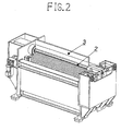
Figure 2 shows a perspective view of the details of the rigid metal structure placed above and in parallel to the forming tool; -
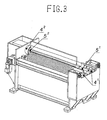
Figure 3 shows a perspective view of the details of the fixed end devices suitable for locking both the ends of the forming tool in place; -
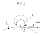
Figure 4 shows a front view of the forming tool elements. -
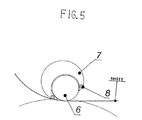
Figure 5 shows a static view of the first stage of the procedure that
the machine object of the present invention, carries out.
-
-
Figure 1 shows a perspective view of the assembly of the machine for manufacturing tubes comprising an elastomeric roller (1) positioned in parallel to the forming tool (2). The metal sheet is positioned between saidroller 1 and thetool 2 for the forming process of the ferrules. -
Figure 2 shows the details of the rigid metal structure (3), preferably plate-shaped and positioned in a parallel position above the forming tool (2), fixed at the sides of the machine with special devices. Saidmetal structure 3 is suitable to prevent or limit the flexure of saidtool 2 generated by the pressure of theroller 1 against the lamina and thetool 2. The absence or limitation of flexure of saidtool 2 due to themetal structure 3 allows to obtain ferrules with a high degree of cylindricity favourably. -
Figure 3 shows the details of the fixed end devices (4.1 and 4.2), preferably jaws, suitable for locking each end (5.1 and 5.2) of the formingtool 2 in a large area, further limiting the flexure generated by theelastomeric roller 1 which presses the lamina and the formingtool 2 during the lamina bending stage, compared to machines readily available in the marketplace. The device 4.1 is closed during the lamina bending stage, hence locking the end 5.1 of thetool 2 in place, opening to the conclusion of the process, allowing the ferrule to be extracted so as to permit subsequent processing cycles. The combination of said devices 4.1 and 4.2 with themetal structure 3 induces greater linearity of saidtool 2 during the forming procedure of the ferrules, obtaining a higher degree of cylindricity compared to that of the machines available in the marketplace. -
Figure 4 shows the formingtool 2 comprising a forming roller (6) incorporated in a shell (7) and auxiliary forming rollers (8) positioned symmetrically on the circumference of the formingroller 6 allowing the ferrule shaped by the elastomeric roller (1) to be reopened. Said formingtool 2, shown inFigure 4 , is suitable for bending metal sheets of various radii based on theauxiliary roller 8 engaged with the bending: the closestauxiliary rollers 8 to the centre of the formingroller 6 realize ferrules of a larger radius compared to the ferrules realized engaging with theauxiliary rollers 8 progressively further with said central position of the formingroller 6. - Various embodiments of the machine for manufacturing tubes can change, in particular in relation to the arrangement and co-presence of all the comprising elements, without departing from the scope of the present invention as defined by the appended claims.
- The procedures that the machine object of the present invention, carries out are as follows.
- In the first stage of the procedure, the bending of the metal sheet is carried out by the first 180°.
- During said stage, the forming
tool 2 is rotated in relation to the central axis of the formingroller 6. With said rotation, one of the auxiliary forming rollers (8) is engaged with the bending of the metal sheet, i.e., the formingroller 6, based on the bending radius of the metal sheet to be realized according to the predetermined processing programme. Said first stage is depicted statically inFigure 5 , showing the formingtool 2, comprising a forming roller (6) incorporated in a shell (7) and auxiliary forming rollers (8), rotated to engage with an auxiliary roller (8) in the bending of the metal sheet. - In a second stage, the metal sheet to be bent is hence subjected to bending as a consequence of the pressure exerted by the
elastomeric roller 1 against the rotated formingtool 2. The bending process is interrupted once the first 180° of metal sheet bending have been reached. The bending of the metal sheet through a further 180° takes place in a third stage, rotating the formingtool 2, in relation to the central axis of the formingroller 6, in a symmetrically opposite position to that taken on during the first stage of the procedure. In the fourth stage of the procedure, the bending of the metal sheet is carried out by a further 180° in the same way as the procedure described for the aforementioned stage two, obtaining a complete ferrule of the required radius. - The manufacturing machine object of the present invention also carries out a bending procedure of at least the first and last centimetre of the metal sheet to be bent, with no auxiliary roller (8) or forming tool (6) intervening in the bending of said portion of said metal sheet.
- The bending procedure for said portions of the metal sheet, carried out by said machine, is carried out through the control, preferably electronic, of the amount of pressure exerted on the metal sheet and on the
tool 2 by the elastomeric roller (1) according to the mechanical resistance of the metal sheet to be bent and the size of the bending radius to be realized.
Claims (4)
- Machine for manufacturing tubes of the type comprising a calendering apparatus that bends the metal sheet provided with an elastomeric roller (1) located in parallel to the forming tool (2), comprising a rigid metal structure (3) disposed in parallel to the forming tool (2) suitable to limit the flexure of said forming tool (2), and comprising embedding devices (4.1 and 4.2) suitable to firmly lock both the ends (5.1 and 5.2) of the forming tool (2) in place characterised in that one embedding device (4.1) comprises two jaws.
- Machine according to claim 1, characterised in that the forming tool (2) comprises:- a forming roller (6) incorporated in a shell (7);- auxiliary forming rollers (8) placed symmetrically on the circumference of the forming roller (6).
- Bending procedure of the metal sheet using the machine according to claims 1 or 2, characterised in that it comprises the following stages:1 the rotation of the forming tool (2) in relation to the central axis of the forming roller (6) to engage one of the auxiliary forming rollers (8) or the forming roller (6) according to the predetermined processing programme;2 bending of the metal sheet up to essentially 180°;3 rotation of the forming tool (2) in relation to the central axis of the forming roller (6) in a diametrically opposite position to that used for stage 1;4 bending of the metal sheet up to essentially 180°.
- Bending procedure according to claim 3, characterised in that for at least the first and /or the last centimetre of the metal sheet the stages from 1 to 4 are substituted by the following stage: pressing of the elastomeric roller (1) against the forming tool (2) according to a predetermined variable programme
Priority Applications (1)
| Application Number | Priority Date | Filing Date | Title |
|---|---|---|---|
| PL08716691T PL2125261T3 (en) | 2007-03-27 | 2008-03-26 | Apparatus and method for bending of sheets for the manufacture of tubes |
Applications Claiming Priority (2)
| Application Number | Priority Date | Filing Date | Title |
|---|---|---|---|
| IT000608A ITMI20070608A1 (en) | 2007-03-27 | 2007-03-27 | MACHINE AND PROCEDURE FOR SHEET METAL CURVATION |
| PCT/EP2008/002369 WO2008116634A1 (en) | 2007-03-27 | 2008-03-26 | Apparatus and method for bending of sheets for the manufacture of tubes |
Publications (2)
| Publication Number | Publication Date |
|---|---|
| EP2125261A1 EP2125261A1 (en) | 2009-12-02 |
| EP2125261B1 true EP2125261B1 (en) | 2011-08-31 |
Family
ID=39580467
Family Applications (1)
| Application Number | Title | Priority Date | Filing Date |
|---|---|---|---|
| EP08716691A Active EP2125261B1 (en) | 2007-03-27 | 2008-03-26 | Apparatus and method for bending of sheets for the manufacture of tubes |
Country Status (5)
| Country | Link |
|---|---|
| EP (1) | EP2125261B1 (en) |
| AT (1) | ATE522294T1 (en) |
| IT (1) | ITMI20070608A1 (en) |
| PL (1) | PL2125261T3 (en) |
| WO (1) | WO2008116634A1 (en) |
Family Cites Families (8)
| Publication number | Priority date | Publication date | Assignee | Title |
|---|---|---|---|---|
| US3205689A (en) * | 1962-10-08 | 1965-09-14 | Union Carbide Corp | Apparatus for forming metal |
| US3371513A (en) * | 1965-12-09 | 1968-03-05 | Kaufmann Tool & Engineering Co | Open end rolling machine |
| US3478555A (en) * | 1966-12-15 | 1969-11-18 | Kaufmann Tool & Eng Corp | Two-roll machine for rolling sheet metal |
| JPS60145223A (en) * | 1984-01-07 | 1985-07-31 | Masanori Mochizuki | Method and device for roll bending |
| CH665572A5 (en) * | 1984-11-30 | 1988-05-31 | Kz Aviatsion Inst Tupoleva | TWO-ROLLER TURNING MACHINE. |
| JP3325037B2 (en) * | 1991-09-20 | 2002-09-17 | アイセル株式会社 | Roll bending equipment |
| DE9305070U1 (en) * | 1993-04-02 | 1994-08-04 | Fastenrath Fasti Werk | Machine for the production of a pipe socket |
| JP3770683B2 (en) * | 1997-02-13 | 2006-04-26 | アイセル株式会社 | Roll bending machine |
-
2007
- 2007-03-27 IT IT000608A patent/ITMI20070608A1/en unknown
-
2008
- 2008-03-26 EP EP08716691A patent/EP2125261B1/en active Active
- 2008-03-26 PL PL08716691T patent/PL2125261T3/en unknown
- 2008-03-26 AT AT08716691T patent/ATE522294T1/en not_active IP Right Cessation
- 2008-03-26 WO PCT/EP2008/002369 patent/WO2008116634A1/en active Application Filing
Also Published As
| Publication number | Publication date |
|---|---|
| PL2125261T3 (en) | 2012-01-31 |
| WO2008116634A1 (en) | 2008-10-02 |
| EP2125261A1 (en) | 2009-12-02 |
| ATE522294T1 (en) | 2011-09-15 |
| ITMI20070608A1 (en) | 2008-09-28 |
Similar Documents
| Publication | Publication Date | Title |
|---|---|---|
| US7610938B2 (en) | Cylindrical rod and method for manufacturing the same | |
| US5711195A (en) | Apparatus and method for precision machining of metal rings | |
| CN110328264B (en) | Bending apparatus for sheet metal material | |
| CA2678716A1 (en) | Apparatus and method for ram bending of tube material | |
| CN102548681A (en) | Method and device for continuously stretch-bend-leveling metal strips | |
| JP2006255953A (en) | Bending apparatus | |
| CN102105236A (en) | Cylinder forming device and cylinder forming method | |
| EP2125261B1 (en) | Apparatus and method for bending of sheets for the manufacture of tubes | |
| WO2011148288A2 (en) | System and method for straightening tubing | |
| CN211386423U (en) | Steel bending machine | |
| JP7238496B2 (en) | pipe bender | |
| CN105013895B (en) | Torsional mode four-roll bending machine | |
| Kale et al. | Control of ovality in pipe bending: a new approach | |
| JP4479327B2 (en) | Punch device for U press in UOE steel pipe manufacturing process | |
| CA2960748A1 (en) | Press forming method and plate material expansion device used in said method | |
| CN113926882A (en) | Edge changing borrowing method for bending center | |
| WO2016175179A1 (en) | Rolling device, curving method, and curving material | |
| KR20100016782A (en) | Metal pipe forming device | |
| EP2351622B1 (en) | Method for manufacturing sealed metal tubes and sealed metal tube manufactured with said method | |
| CN210966505U (en) | Novel hydraulic pipe bender | |
| JPH08150419A (en) | Pipe bender | |
| KR101630121B1 (en) | Steel plate bending apparatus | |
| US11565297B2 (en) | Bending machine and method for controlling the bending machine | |
| JP2006297465A5 (en) | ||
| CN216004618U (en) | Inflatable rolling type slitting device |
Legal Events
| Date | Code | Title | Description |
|---|---|---|---|
| PUAI | Public reference made under article 153(3) epc to a published international application that has entered the european phase |
Free format text: ORIGINAL CODE: 0009012 |
|
| 17P | Request for examination filed |
Effective date: 20090914 |
|
| AK | Designated contracting states |
Kind code of ref document: A1 Designated state(s): AT BE BG CH CY CZ DE DK EE ES FI FR GB GR HR HU IE IS IT LI LT LU LV MC MT NL NO PL PT RO SE SI SK TR |
|
| DAX | Request for extension of the european patent (deleted) | ||
| GRAP | Despatch of communication of intention to grant a patent |
Free format text: ORIGINAL CODE: EPIDOSNIGR1 |
|
| GRAC | Information related to communication of intention to grant a patent modified |
Free format text: ORIGINAL CODE: EPIDOSCIGR1 |
|
| GRAS | Grant fee paid |
Free format text: ORIGINAL CODE: EPIDOSNIGR3 |
|
| GRAA | (expected) grant |
Free format text: ORIGINAL CODE: 0009210 |
|
| AK | Designated contracting states |
Kind code of ref document: B1 Designated state(s): AT BE BG CH CY CZ DE DK EE ES FI FR GB GR HR HU IE IS IT LI LT LU LV MC MT NL NO PL PT RO SE SI SK TR |
|
| REG | Reference to a national code |
Ref country code: GB Ref legal event code: FG4D Ref country code: CH Ref legal event code: EP |
|
| REG | Reference to a national code |
Ref country code: IE Ref legal event code: FG4D |
|
| REG | Reference to a national code |
Ref country code: DE Ref legal event code: R096 Ref document number: 602008009306 Country of ref document: DE Effective date: 20111103 |
|
| REG | Reference to a national code |
Ref country code: CH Ref legal event code: NV Representative=s name: ISLER & PEDRAZZINI AG |
|
| REG | Reference to a national code |
Ref country code: NL Ref legal event code: VDEP Effective date: 20110831 |
|
| LTIE | Lt: invalidation of european patent or patent extension |
Effective date: 20110831 |
|
| PG25 | Lapsed in a contracting state [announced via postgrant information from national office to epo] |
Ref country code: NL Free format text: LAPSE BECAUSE OF FAILURE TO SUBMIT A TRANSLATION OF THE DESCRIPTION OR TO PAY THE FEE WITHIN THE PRESCRIBED TIME-LIMIT Effective date: 20110831 Ref country code: IS Free format text: LAPSE BECAUSE OF FAILURE TO SUBMIT A TRANSLATION OF THE DESCRIPTION OR TO PAY THE FEE WITHIN THE PRESCRIBED TIME-LIMIT Effective date: 20111231 Ref country code: HR Free format text: LAPSE BECAUSE OF FAILURE TO SUBMIT A TRANSLATION OF THE DESCRIPTION OR TO PAY THE FEE WITHIN THE PRESCRIBED TIME-LIMIT Effective date: 20110831 Ref country code: SE Free format text: LAPSE BECAUSE OF FAILURE TO SUBMIT A TRANSLATION OF THE DESCRIPTION OR TO PAY THE FEE WITHIN THE PRESCRIBED TIME-LIMIT Effective date: 20110831 Ref country code: LT Free format text: LAPSE BECAUSE OF FAILURE TO SUBMIT A TRANSLATION OF THE DESCRIPTION OR TO PAY THE FEE WITHIN THE PRESCRIBED TIME-LIMIT Effective date: 20110831 Ref country code: FI Free format text: LAPSE BECAUSE OF FAILURE TO SUBMIT A TRANSLATION OF THE DESCRIPTION OR TO PAY THE FEE WITHIN THE PRESCRIBED TIME-LIMIT Effective date: 20110831 Ref country code: NO Free format text: LAPSE BECAUSE OF FAILURE TO SUBMIT A TRANSLATION OF THE DESCRIPTION OR TO PAY THE FEE WITHIN THE PRESCRIBED TIME-LIMIT Effective date: 20111130 |
|
| REG | Reference to a national code |
Ref country code: PL Ref legal event code: T3 |
|
| REG | Reference to a national code |
Ref country code: AT Ref legal event code: MK05 Ref document number: 522294 Country of ref document: AT Kind code of ref document: T Effective date: 20110831 |
|
| PG25 | Lapsed in a contracting state [announced via postgrant information from national office to epo] |
Ref country code: CY Free format text: LAPSE BECAUSE OF FAILURE TO SUBMIT A TRANSLATION OF THE DESCRIPTION OR TO PAY THE FEE WITHIN THE PRESCRIBED TIME-LIMIT Effective date: 20110831 Ref country code: AT Free format text: LAPSE BECAUSE OF FAILURE TO SUBMIT A TRANSLATION OF THE DESCRIPTION OR TO PAY THE FEE WITHIN THE PRESCRIBED TIME-LIMIT Effective date: 20110831 Ref country code: SI Free format text: LAPSE BECAUSE OF FAILURE TO SUBMIT A TRANSLATION OF THE DESCRIPTION OR TO PAY THE FEE WITHIN THE PRESCRIBED TIME-LIMIT Effective date: 20110831 Ref country code: LV Free format text: LAPSE BECAUSE OF FAILURE TO SUBMIT A TRANSLATION OF THE DESCRIPTION OR TO PAY THE FEE WITHIN THE PRESCRIBED TIME-LIMIT Effective date: 20110831 Ref country code: GR Free format text: LAPSE BECAUSE OF FAILURE TO SUBMIT A TRANSLATION OF THE DESCRIPTION OR TO PAY THE FEE WITHIN THE PRESCRIBED TIME-LIMIT Effective date: 20111201 |
|
| PG25 | Lapsed in a contracting state [announced via postgrant information from national office to epo] |
Ref country code: BE Free format text: LAPSE BECAUSE OF FAILURE TO SUBMIT A TRANSLATION OF THE DESCRIPTION OR TO PAY THE FEE WITHIN THE PRESCRIBED TIME-LIMIT Effective date: 20110831 |
|
| PG25 | Lapsed in a contracting state [announced via postgrant information from national office to epo] |
Ref country code: CZ Free format text: LAPSE BECAUSE OF FAILURE TO SUBMIT A TRANSLATION OF THE DESCRIPTION OR TO PAY THE FEE WITHIN THE PRESCRIBED TIME-LIMIT Effective date: 20110831 Ref country code: SK Free format text: LAPSE BECAUSE OF FAILURE TO SUBMIT A TRANSLATION OF THE DESCRIPTION OR TO PAY THE FEE WITHIN THE PRESCRIBED TIME-LIMIT Effective date: 20110831 |
|
| PG25 | Lapsed in a contracting state [announced via postgrant information from national office to epo] |
Ref country code: IT Free format text: LAPSE BECAUSE OF FAILURE TO SUBMIT A TRANSLATION OF THE DESCRIPTION OR TO PAY THE FEE WITHIN THE PRESCRIBED TIME-LIMIT Effective date: 20110831 Ref country code: RO Free format text: LAPSE BECAUSE OF FAILURE TO SUBMIT A TRANSLATION OF THE DESCRIPTION OR TO PAY THE FEE WITHIN THE PRESCRIBED TIME-LIMIT Effective date: 20110831 Ref country code: EE Free format text: LAPSE BECAUSE OF FAILURE TO SUBMIT A TRANSLATION OF THE DESCRIPTION OR TO PAY THE FEE WITHIN THE PRESCRIBED TIME-LIMIT Effective date: 20110831 Ref country code: PT Free format text: LAPSE BECAUSE OF FAILURE TO SUBMIT A TRANSLATION OF THE DESCRIPTION OR TO PAY THE FEE WITHIN THE PRESCRIBED TIME-LIMIT Effective date: 20120102 |
|
| PG25 | Lapsed in a contracting state [announced via postgrant information from national office to epo] |
Ref country code: DK Free format text: LAPSE BECAUSE OF FAILURE TO SUBMIT A TRANSLATION OF THE DESCRIPTION OR TO PAY THE FEE WITHIN THE PRESCRIBED TIME-LIMIT Effective date: 20110831 |
|
| PLBE | No opposition filed within time limit |
Free format text: ORIGINAL CODE: 0009261 |
|
| STAA | Information on the status of an ep patent application or granted ep patent |
Free format text: STATUS: NO OPPOSITION FILED WITHIN TIME LIMIT |
|
| 26N | No opposition filed |
Effective date: 20120601 |
|
| REG | Reference to a national code |
Ref country code: DE Ref legal event code: R097 Ref document number: 602008009306 Country of ref document: DE Effective date: 20120601 |
|
| PG25 | Lapsed in a contracting state [announced via postgrant information from national office to epo] |
Ref country code: MC Free format text: LAPSE BECAUSE OF NON-PAYMENT OF DUE FEES Effective date: 20120331 |
|
| GBPC | Gb: european patent ceased through non-payment of renewal fee |
Effective date: 20120326 |
|
| REG | Reference to a national code |
Ref country code: IE Ref legal event code: MM4A |
|
| PG25 | Lapsed in a contracting state [announced via postgrant information from national office to epo] |
Ref country code: IE Free format text: LAPSE BECAUSE OF NON-PAYMENT OF DUE FEES Effective date: 20120326 Ref country code: GB Free format text: LAPSE BECAUSE OF NON-PAYMENT OF DUE FEES Effective date: 20120326 |
|
| PG25 | Lapsed in a contracting state [announced via postgrant information from national office to epo] |
Ref country code: ES Free format text: LAPSE BECAUSE OF FAILURE TO SUBMIT A TRANSLATION OF THE DESCRIPTION OR TO PAY THE FEE WITHIN THE PRESCRIBED TIME-LIMIT Effective date: 20111211 |
|
| PG25 | Lapsed in a contracting state [announced via postgrant information from national office to epo] |
Ref country code: BG Free format text: LAPSE BECAUSE OF FAILURE TO SUBMIT A TRANSLATION OF THE DESCRIPTION OR TO PAY THE FEE WITHIN THE PRESCRIBED TIME-LIMIT Effective date: 20111130 |
|
| PG25 | Lapsed in a contracting state [announced via postgrant information from national office to epo] |
Ref country code: MT Free format text: LAPSE BECAUSE OF FAILURE TO SUBMIT A TRANSLATION OF THE DESCRIPTION OR TO PAY THE FEE WITHIN THE PRESCRIBED TIME-LIMIT Effective date: 20110831 |
|
| PG25 | Lapsed in a contracting state [announced via postgrant information from national office to epo] |
Ref country code: TR Free format text: LAPSE BECAUSE OF FAILURE TO SUBMIT A TRANSLATION OF THE DESCRIPTION OR TO PAY THE FEE WITHIN THE PRESCRIBED TIME-LIMIT Effective date: 20110831 |
|
| PG25 | Lapsed in a contracting state [announced via postgrant information from national office to epo] |
Ref country code: LU Free format text: LAPSE BECAUSE OF NON-PAYMENT OF DUE FEES Effective date: 20120326 |
|
| PG25 | Lapsed in a contracting state [announced via postgrant information from national office to epo] |
Ref country code: HU Free format text: LAPSE BECAUSE OF FAILURE TO SUBMIT A TRANSLATION OF THE DESCRIPTION OR TO PAY THE FEE WITHIN THE PRESCRIBED TIME-LIMIT Effective date: 20080326 |
|
| REG | Reference to a national code |
Ref country code: FR Ref legal event code: PLFP Year of fee payment: 9 |
|
| REG | Reference to a national code |
Ref country code: FR Ref legal event code: PLFP Year of fee payment: 10 |
|
| PGFP | Annual fee paid to national office [announced via postgrant information from national office to epo] |
Ref country code: CH Payment date: 20170313 Year of fee payment: 10 |
|
| REG | Reference to a national code |
Ref country code: FR Ref legal event code: PLFP Year of fee payment: 11 |
|
| REG | Reference to a national code |
Ref country code: CH Ref legal event code: PL |
|
| PG25 | Lapsed in a contracting state [announced via postgrant information from national office to epo] |
Ref country code: CH Free format text: LAPSE BECAUSE OF NON-PAYMENT OF DUE FEES Effective date: 20180331 Ref country code: LI Free format text: LAPSE BECAUSE OF NON-PAYMENT OF DUE FEES Effective date: 20180331 |
|
| PGFP | Annual fee paid to national office [announced via postgrant information from national office to epo] |
Ref country code: FR Payment date: 20230327 Year of fee payment: 16 |
|
| PGFP | Annual fee paid to national office [announced via postgrant information from national office to epo] |
Ref country code: PL Payment date: 20230316 Year of fee payment: 16 |
|
| PGFP | Annual fee paid to national office [announced via postgrant information from national office to epo] |
Ref country code: DE Payment date: 20230330 Year of fee payment: 16 |