EP2124850B1 - Orthese - Google Patents
Orthese Download PDFInfo
- Publication number
- EP2124850B1 EP2124850B1 EP08706879A EP08706879A EP2124850B1 EP 2124850 B1 EP2124850 B1 EP 2124850B1 EP 08706879 A EP08706879 A EP 08706879A EP 08706879 A EP08706879 A EP 08706879A EP 2124850 B1 EP2124850 B1 EP 2124850B1
- Authority
- EP
- European Patent Office
- Prior art keywords
- joint
- proximal
- orthotic
- distal
- pivoting
- Prior art date
- Legal status (The legal status is an assumption and is not a legal conclusion. Google has not performed a legal analysis and makes no representation as to the accuracy of the status listed.)
- Not-in-force
Links
- 210000002414 leg Anatomy 0.000 claims description 65
- 210000003127 knee Anatomy 0.000 claims description 43
- 239000000463 material Substances 0.000 claims description 9
- 210000001503 joint Anatomy 0.000 description 45
- 210000003414 extremity Anatomy 0.000 description 7
- 210000000629 knee joint Anatomy 0.000 description 6
- 230000007423 decrease Effects 0.000 description 5
- 210000000689 upper leg Anatomy 0.000 description 5
- 210000002310 elbow joint Anatomy 0.000 description 3
- 238000001356 surgical procedure Methods 0.000 description 3
- 230000035876 healing Effects 0.000 description 2
- 238000002347 injection Methods 0.000 description 2
- 239000007924 injection Substances 0.000 description 2
- 210000003041 ligament Anatomy 0.000 description 2
- 210000001519 tissue Anatomy 0.000 description 2
- 230000006978 adaptation Effects 0.000 description 1
- 238000010276 construction Methods 0.000 description 1
- 230000000694 effects Effects 0.000 description 1
- 210000000245 forearm Anatomy 0.000 description 1
- 238000001746 injection moulding Methods 0.000 description 1
- 238000004519 manufacturing process Methods 0.000 description 1
- 125000006850 spacer group Chemical group 0.000 description 1
- 230000008961 swelling Effects 0.000 description 1
Images



Classifications
-
- A—HUMAN NECESSITIES
- A61—MEDICAL OR VETERINARY SCIENCE; HYGIENE
- A61F—FILTERS IMPLANTABLE INTO BLOOD VESSELS; PROSTHESES; DEVICES PROVIDING PATENCY TO, OR PREVENTING COLLAPSING OF, TUBULAR STRUCTURES OF THE BODY, e.g. STENTS; ORTHOPAEDIC, NURSING OR CONTRACEPTIVE DEVICES; FOMENTATION; TREATMENT OR PROTECTION OF EYES OR EARS; BANDAGES, DRESSINGS OR ABSORBENT PADS; FIRST-AID KITS
- A61F5/00—Orthopaedic methods or devices for non-surgical treatment of bones or joints; Nursing devices ; Anti-rape devices
- A61F5/01—Orthopaedic devices, e.g. long-term immobilising or pressure directing devices for treating broken or deformed bones such as splints, casts or braces
- A61F5/0102—Orthopaedic devices, e.g. long-term immobilising or pressure directing devices for treating broken or deformed bones such as splints, casts or braces specially adapted for correcting deformities of the limbs or for supporting them; Ortheses, e.g. with articulations
- A61F5/0123—Orthopaedic devices, e.g. long-term immobilising or pressure directing devices for treating broken or deformed bones such as splints, casts or braces specially adapted for correcting deformities of the limbs or for supporting them; Ortheses, e.g. with articulations for the knees
-
- A—HUMAN NECESSITIES
- A61—MEDICAL OR VETERINARY SCIENCE; HYGIENE
- A61F—FILTERS IMPLANTABLE INTO BLOOD VESSELS; PROSTHESES; DEVICES PROVIDING PATENCY TO, OR PREVENTING COLLAPSING OF, TUBULAR STRUCTURES OF THE BODY, e.g. STENTS; ORTHOPAEDIC, NURSING OR CONTRACEPTIVE DEVICES; FOMENTATION; TREATMENT OR PROTECTION OF EYES OR EARS; BANDAGES, DRESSINGS OR ABSORBENT PADS; FIRST-AID KITS
- A61F5/00—Orthopaedic methods or devices for non-surgical treatment of bones or joints; Nursing devices ; Anti-rape devices
- A61F5/01—Orthopaedic devices, e.g. long-term immobilising or pressure directing devices for treating broken or deformed bones such as splints, casts or braces
- A61F5/0102—Orthopaedic devices, e.g. long-term immobilising or pressure directing devices for treating broken or deformed bones such as splints, casts or braces specially adapted for correcting deformities of the limbs or for supporting them; Ortheses, e.g. with articulations
- A61F2005/0132—Additional features of the articulation
- A61F2005/0137—Additional features of the articulation with two parallel pivots
- A61F2005/0139—Additional features of the articulation with two parallel pivots geared
Definitions
- the invention relates to an orthosis, in particular a knee brace, with two load joints, each having a proximal and a distal leg.
- the invention relates to an orthosis principle for different body parts.
- Knee braces are used to protect a knee joint against dorsal-ventricular kinking movements.
- the knee brace is attached to a thigh and a lower leg so that the two load joints are arranged on both sides of the side of the knee joint to be protected.
- Occurring buckling loads are absorbed by the knee brace and passed past the knee in the upper or lower leg.
- the load joints should be close to the knee joint.
- Knee braces are typically used after knee surgery to protect the still vulnerable ligaments of the operated knee. After knee surgery, the tissue around the knee is regularly swollen and swells during the healing process. This changes the width of the knee and the distance between the load joints must be adjusted to ensure optimal protection against kinking.
- the knee braces are adaptable to a small extent and are used in conjunction with spacer elements which are positioned between the load joints and the knee.
- Knee orthoses are known in the prior art, in which the distal leg and the proximal legs are each transversely displaceable against each other by means of a bracing device.
- a disadvantage of this is the complex construction of the bracing, which is also not very user friendly.
- a knee brace is known in which the proximal legs are fastened by nubs to a central tab. To vary the distance between the load joints, the distal legs are attached to other nubs. The disadvantage of this is that the distance is not infinitely variable. Another disadvantage is the low user-friendliness.
- a knee brace with a solid-state joint known.
- the disadvantage of this is that the distance between the two proximal legs can not be fixed.
- a load joint From the EP 1 676 549 A1 is known a load joint.
- a ball and socket orthosis is known in which the proximal legs are fixedly secured to a sleeve.
- a knee joint relief post is known in which the proximal legs are attached to a thigh shank.
- the invention has for its object to propose an orthosis, in particular a knee brace, which is easier to adapt to a changing knee width.
- the invention solves the problem by an orthosis with the features of claim 1.
- An advantage of the invention is that a continuous adjustment of the distance between the load joints to the knee width is possible. For example, if the swelling in the knee fluctuates during the course of the day, the orthosis can easily be readjusted.
- an orthosis according to the invention is also quickly and easily adaptable, which leads to a time saving both in the patient as well as in medical professionals who is involved in the adjustment of the orthosis.
- An orthosis according to the invention also has a large variability of the distance between the load joints, so that a smaller number of types is sufficient to detect all occurring knee widths.
- a smaller number of types is sufficient to detect all occurring knee widths.
- Important components of the orthosis such as the legs, can also be designed as injection molded parts, resulting in a fast and cost-effective production, even in large quantities.
- the articulated joints are those joints of the orthosis that move when the knee is bent or stretched.
- the proximal joint and / or the distal joint is a swivel joint, in particular a fixable swivel joint.
- Swivel joints are particularly simple and very stable to produce and provide sufficient strength for the orthosis.
- a fixable swivel joint By a fixable swivel joint, the distance between the two load joints can be adjusted continuously and set immediately after setting. As a result, the orthosis is particularly quickly and easily adaptable to a changing knee width.
- proximal hinge pivot axis passes through the proximal hinge.
- the proximal joint or the distal joint is a scissors hinge.
- a scissors-type rotary joint is to be understood as meaning that the two proximal or distal legs extend beyond the rotary joint. If the distance between the two load joints decreases, the distance between the two sections of the legs protruding beyond the scissors-type swivel joint also decreases with a scissors-type swivel joint.
- proximal joint and / or the distal joint may be laterally disposed on the respective legs so that the distance between the portions extending beyond the hinge decreases as the distance between the load joints increases.
- proximal joint or only the distal joint is designed as a scissors hinge, the other hand, not.
- the rotary joint is pivotable about a pivot joint pivot axis which is perpendicular to a load joint pivot axis about which the two load joints are pivotable.
- the swivel pivot axis then runs in a dorsal-ventral direction.
- the two distal legs each have a first distal partial leg and a second distal partial leg and each comprise a distal compensating joint, wherein the distal compensating joints pivotally connect the respective partial legs about a pivot axis which is parallel to the pivot pivot axis.
- Particularly preferred corresponding compensating joints are also provided in the proximal limbs.
- These compensating joints may be hinged joints, for example.
- the compensating joints are formed by material tapers of the respective legs.
- the compensating joints are formed by regions in which the material has a smaller modulus of elasticity than the surrounding material.
- the proximal legs extend behind the proximal joint into a quarter shell, so that both quarter shells form a proximal half shell for fastening the orthosis to a limb.
- the orthosis is a knee brace
- the half shell is designed to attach the knee brace to a thigh.
- the distal legs preferably extend into a quarter shell behind the distal joint, so that both quarter shells form a distal half shell for fastening the orthosis to a limb.
- the distal half shell is used to attach the knee brace to a lower leg.
- the proximal and / or distal quarter shells are flexible.
- an elbow orthosis with two load joints each having a proximal and a distal leg.
- Such elbow braces are used to protect an elbow joint against lateral and medial kinking movements.
- the elbow orthosis is attached to an upper arm and a forearm so that the two load joints are arranged on both sides of the elbow joint to be protected.
- Occurring buckling loads are absorbed by the elbow orthosis and passed past the elbow into the upper or lower arm.
- the load joints should be close to the elbow joint.
- Elbow orthoses are typically used after operations on the elbow to protect the still vulnerable ligaments of the operated elbow. After elbow surgery, the tissue in the area of the elbow is sometimes swollen and swells during the healing process. This changes the width of the elbow and the distance between the load joints must be adjusted to ensure optimum protection against kinking.
- the load joints designed as ball joints so advantageously compensating joints can be omitted.
- pads are attached to the load joints, so that the load joints are not in direct contact with the knee joint of the patient.
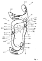
- FIG. 1 shows a knee brace 10 with a left load joint 12 and a right load joint 14.
- the left load joint 12 connects a left proximal leg 16.1 with a left distal leg 18.1 in shape and is designed as a polycentric pivot.
- the left load joint 12 includes a proximal condyle 20.1 and a distal condyle 22.1, each having teeth. The teeth mesh with each other when the proximal leg 16.1 pivots relative to the distal leg 18.1.
- the proximal and distal legs 16.1 and 18.1 pivot in a temporally variable load joint rotation axis D to each other, which is always parallel to connecting axes D1 and D2, the centers of the two proximal rod ends 20.1, 20.2 and the two distal rod ends 22.1, 22.2 connect with each other.
- the proximal leg 16.1 and distal leg 18.1 have a flat, band-like shape and are manufactured by injection molding.
- the knee brace 10 also includes a right proximal leg 16.2 and a right distal leg 18.2, which is constructed substantially mirror-inverted to the left proximal legs 16.1 and the left distal leg 18.1. To avoid repetition, only the components of a page are described below. For each such component with the suffix ".1" on the other side corresponds to a component that carries the suffix ".2". .
- the left proximal leg 16.1 and the right proximal leg 16.2. are pivotally connected in a proximal joint 24 and fixed against each other and can about a proximal joint axis of rotation P against each other be pivoted.
- the proximal joint rotation axis P is perpendicular to the load joint rotation axis D.
- the proximal left leg 16.1 extends beyond the proximal joint 24 and ends in a quarter shell 26.1.
- the right proximal limb 16.2 runs out into a quarter shell 26.2. If the two proximal legs 16.1, 16.2 are pivoted against each other so that the distance d between the left load joint 12 and the right-hand load joint 14 decreases, so does the distance between the quarter shells 26.1 and 26.2 from.
- the proximal joint 24 is therefore a scissors hinge.
- the right proximal leg 16.2 has a first proximal partial leg 28.2 and a second proximal partial leg 30.2, which are connected to one another via a proximal compensating joint 32.2 and which are pivotable relative to one another about a proximal compensating joint rotational axis A.2.
- the right distal leg 18.2 has a first distal partial leg 34.2. and a second distal part leg 36.2, which are connected to each other by a distal compensating joint 38.2 and are mutually pivotable about a distal compensating joint axis of rotation U.2.
- the distal compensating joint rotation axis U.2 also runs parallel to the proximal joint rotation axis P.
- the distal compensating joints 38.1, 38.2 and the proximal compensating joints 32.1 and 32.2. are formed by hinges.
- the respective limbs 16.1, 16.2 or 18.1, 18.2 have a material taper in the region of the articulation joints 32.1, 32.2 and 38.1, 38.2.
- a material with a lower modulus of elasticity is used in the corresponding area.
- the distal legs 18.1 and 18.2 are pivotally connected together in a distal joint 40 about a distal hinge axis of rotation Q and continue into respective quarter shells 42.1, 42.2.
- the quarter shells 42.1, 42.2 form a half-shell with which the knee brace 10 can be attached to a non-illustrated lower leg of a patient, for example with bandages.
- the distal joint 40 is constructed like the proximal joint 24 and also constitutes a scissors hinge.
- the quarter shells 26.1, 26.2 and 42.1, 42.2 are formed of a flexible material so that they are adaptable to the shape of the respective body member to which they are to be attached.
- the legs 16.1, 16.2, 18.1, 18.2 are made for example as plastic injection molded parts.
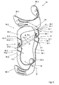
- FIG. 2 shows an alternative embodiment of a knee orthosis 10 according to the invention, in which like reference numerals designate like components.
- the proximal joint 24 is designed as a hinge, but not as a scissor hinge. Therefore, if the distance d between the left load joint 12 and the right-hand load joint 14 decreases, the distance between the two quarter-shells 26.1 and 26.2 increases.
- the distal joint 40 as well as the proximal joint 24 according to FIG FIG. 2 be educated.
- the proximal joint 24 and the distal joint 40 both of which are designed as fixable hinges, dissolved and the angle between the proximal legs 16.1, 16.2 and the distal legs 18.1, 18.2 is adjusted so that the Distance d between the load joints 12 and 14 has the desired size. Subsequently, the proximal joint 24 and the distal joint 40 are fixed and the knee brace 10 is attached to the upper or lower leg of the patient.
- FIG. 3 shows an alternative embodiment of a knee orthosis 10 according to the invention, in which both the proximal joint 24 and the distal joint 40 are formed as scissors-hinges.
- the proximal compensation joints 32.1, 32.2 and the distal compensation joints 38.1, 38.2 are formed by material tapers and can therefore also be referred to as solid-body joints.
- FIG. 5 shows an alternative embodiment of a knee orthosis 10 according to the invention, in which the load joints 12, 14 are formed as ball joints and in which therefore compensating joints are dispensable.
- Non-illustrated pads are attached to the ball joints to conveniently secure the knee brace 10 to the patient's body.
Landscapes
- Health & Medical Sciences (AREA)
- Nursing (AREA)
- Orthopedic Medicine & Surgery (AREA)
- Engineering & Computer Science (AREA)
- Biomedical Technology (AREA)
- Heart & Thoracic Surgery (AREA)
- Vascular Medicine (AREA)
- Life Sciences & Earth Sciences (AREA)
- Animal Behavior & Ethology (AREA)
- General Health & Medical Sciences (AREA)
- Public Health (AREA)
- Veterinary Medicine (AREA)
- Orthopedics, Nursing, And Contraception (AREA)
- Rehabilitation Tools (AREA)
- Massaging Devices (AREA)
- Medicines Containing Plant Substances (AREA)
- Prostheses (AREA)
Description
- Die Erfindung betrifft eine Orthese, insbesondere eine Knieorthese, mit zwei Lastgelenken, die jeweils einen proximalen und einen distalen Schenkel aufweisen. In anderen Worten betrifft die Erfindung ein Orthesenprinzip für verschiedene Körperteile.
- Derartige Orthesen werden zum Schutz entsprechender Bänder vor Überbeanspruchung durch innere oder äußere Krafteinwirkungen so angewendet, dass Bewegungen von Körperteilen eingeschränkt und/oder uneingeschränkt möglich sind. Knieorthesen werden zum Schützen eines Kniegelenks gegen dorsalventrale Knickbewegungen verwendet. Dazu wird die Knieorthese so an einem Oberschenkel und einem Unterschenkel befestigt, dass die beiden Lastgelenke beidseits seitlich des zu schützenden Kniegelenks angeordnet sind. Auftretende Knicklasten werden von der Knieorthese aufgenommen und an dem Knie vorbei in den Ober- bzw. Unterschenkel eingeleitet. Um eine sichere Ableitung von Knickkräften zu gewährleisten, sollten die Lastgelenke dicht am Kniegelenk anliegen.
- Knieorthesen werden in der Regel nach Operationen am Knie verwendet, um die noch empfindlichen Bänder des operierten Knies zu schützen. Nach Knieoperationen ist das Gewebe im Bereich des Knies regelmäßig geschwollen und schwillt während des Heilungsprozesses ab. Damit ändert sich die Breite des Knies und der Abstand zwischen den Lastgelenken muss nachgestellt werden, um stets einen optimalen Schutz gegen Knickbewegungen sicherzustellen.
- Zur Feineinstellung des Abstandes zwischen den Lastgelenken sind die Knieorthesen zu einem kleinen Teil adaptierbar und werden zusammen mit Distanzelementen verwendet, die zwischen die Lastgelenke und das Knie positioniert werden.
- Aus der
US 4 886 054 und derDE 44 18 855 A1 , der der nächste Stand der Technik darstellt, sind Knieorthesen bekannt, bei der die distalen Schenkel und die proximalen Schenkel jeweils querverschieblich gegeneinander mittels einer Verspanneinrichtung festlegbar sind. Nachteilig hieran ist die aufwändige Konstruktion der Verspanneinrichtung, die zudem wenig benutzerfreundlich ist. - Aus der
DE 37 38 664 A1 ist eine Knieorthese bekannt, bei der die proximalen Schenkel mittels Noppen an einer zentralen Lasche befestigt sind. Zum Verändern des Abstands zwischen den Lastgelenken, werden die distalen Schenkel an anderen Noppen befestigt. Nachteilig hieran ist, dass der Abstand nicht stufenlos variierbar ist. Ein weiterer Nachteil ist die geringe Bedienerfreundlichkeit. - Aus der
WO 2006/078428 A2 ist eine Knieorthese mit einem Festkörpergelenk bekannt. Nachteilig hieran ist, dass der Abstand zwischen den beiden proximalen Schenkeln nicht festlegbar ist. Aus derEP 1 676 549 A1 ist ein Lastgelenk bekannt. Aus derDE 10 2005 008 340 A1 ist eine Kugelgelenk-Orthese bekannt, bei der die proximalen Schenkel an einer Hülse fest befestigt sind. Aus derDE 297 05 958 U1 ist eine Kniegelenkentlastungsstütze bekannt, bei der die proximalen Schenkel an einer schnürbaren Oberschenkelhülse befestigt sind. - Der Erfindung liegt die Aufgabe zugrunde, eine Orthese, insbesondere eine Knieorthese, vorzuschlagen, die leichter an eine sich ändernde Kniebreite anpassbar ist.
- Die Erfindung löst das Problem durch eine Orthese mit den Merkmalen von Anspruch 1.
- Vorteilhaft an der Erfindung ist, dass eine stufenlose Anpassung des Abstands zwischen den Lastgelenken an die Kniebreite möglich ist. Schwankt beispielsweise die Schwellung im Knie während des Tagesablaufs, so kann die Orthese leicht nachgestellt werden.
- Vorteilhafterweise ist eine erfindungsgemäße Orthese zudem schnell und einfach anpassbar, was zu einer Zeitersparnis sowohl beim Patienten als auch bei medizinischem Fachpersonal führt, das mit der Einstellung der Orthese befasst ist.
- Eine erfindungsgemäße Orthese weist zudem eine große Veränderbarkeit des Abstands zwischen den Lastgelenken auf, so dass eine geringere Anzahl an Typen ausreichend ist, um sämtliche auftretende Kniebreiten zu erfassen. Bei dem Vertrieb erfindungsgemäßer Orthesen müssen daher weniger Varianten vorgehalten werden, was Lagerkapazität spart.
- Wichtige Komponenten der Orthese, wie beispielsweise die Schenkel, können zudem als Spritzgussteile ausgebildet werden, was zu einer schnellen und kostengünstigen Fertigung auch in großen Stückzahlen führt.
- Im Rahmen der vorliegenden Erfindung werden unter den Lastgelenken diejenigen Gelenke der Orthese verstanden, die sich bewegen, wenn das Knie gebeugt oder gestreckt wird.
- Bevorzugt ist das Proximal-Gelenk und/oder das Distal-Gelenk ein Drehgelenk, insbesondere ein festlegbares Drehgelenk. Drehgelenke sind besonders einfach und sehr stabil herstellbar und bieten eine hinreichende Festigkeit für die Orthese. Durch ein festlegbares Drehgelenk kann der Abstand zwischen den beiden Lastgelenken stufenlos eingestellt und unmittelbar nach dem Einstellen festgelegt werden. Dadurch wird die Orthese besonders schnell und einfach an eine sich verändernde Kniebreite anpassbar.
- In einer bevorzugten Ausführungsform verläuft die Proximal-Gelenk-Schwenkachse durch das Proximal-Gelenk.
- Besonders bevorzugt ist das Proximal-Gelenk bzw. das Distal-Gelenk ein Scheren-Drehgelenk. Unter einem Scheren-Drehgelenk ist insbesondere zu verstehen, dass sich die beiden proximalen bzw. distalen Schenkel über das Drehgelenk hinaus erstrecken. Verringert sich der Abstand zwischen den beiden Lastgelenken, so verringert sich bei einem Scheren-Drehgelenk auch der Abstand der beiden Abschnitte der Schenkel, die über das Scheren-Drehgelenk hinausragen.
- Alternativ kann das Proximal-Gelenk und/oder das Distal-Gelenk seitlich an den jeweiligen Schenkeln angeordnet sein, so dass sich der Abstand zwischen den über das Drehgelenk hinaus erstreckenden Abschnitten abnimmt, wenn der Abstand zwischen den Lastgelenken zunimmt. Selbstverständlich ist es auch möglich, dass nur das Proximal-Gelenk oder nur das Distal-Gelenk als Scheren-Drehgelenk ausgebildet ist, das andere hingegen nicht.
- Bevorzugt ist das Drehgelenk um eine Drehgelenk-Schwenkachse schwenkbar, die senkrecht zu einer Lastgelenk-Schwenkachse verläuft, um die die beiden Lastgelenke schwenkbar sind. Die Drehgelenk-Schwenkachse verläuft dann in dorsal-ventraler Richtung.
- In einer bevorzugten Ausführungsform weisen die beiden distalen Schenkel jeweils einen ersten distalen Teilschenkel und einen zweiten distalen Teilschenkel auf und umfassen jeweils ein distales Ausgleichsgelenk, wobei die distalen Ausgleichsgelenke die jeweiligen Teilschenkel um eine Schwenkachse schwenkbar miteinander verbinden, die parallel zu der Drehgelenk-Schwenkachse verläuft. Besonders bevorzugt sind entsprechende Ausgleichsgelenke auch in den proximalen Schenkeln vorgesehen. Diese Ausgleichsgelenke können beispielsweise Scharniergelenke sein. Alternativ sind die Ausgleichsgelenke durch Materialverjüngungen der jeweiligen Schenkel gebildet. Alternativ oder additiv werden die Ausgleichsgelenke durch Bereiche gebildet, in denen das Material einen gegenüber dem umgebenden Material kleineren Elastizitätsmodul aufweist. Wenn die proximalen Schenkel im Proximal-Gelenk gegeneinander verschwenkt werden, so verändert sich der Abstand zwischen den Lastgelenken. Die Ausgleichsgelenke sorgen dafür, dass die beiden Lastgelenke weiter um eine für beide gleiche Schwenkachse schwenken. Dadurch werden die Lastgelenke geschont.
- In einer bevorzugten Ausführungsform laufen die proximalen Schenkel vom jeweiligen Lastgelenk aus gesehen hinter dem Proximal-Gelenk in eine Viertelschale aus, so dass beide Viertelschalen eine proximale Halbschale zum Befestigen der Orthese an einem Körperglied bilden. Wenn es sich bei der Orthese um eine Knieorthese handelt, so ist die Halbschale zur Befestigung der Knieorthese an einem Oberschenkel ausgebildet.
- Auf analoge Weise laufen die distalen Schenkel vom jeweiligen Lastgelenk aus gesehen bevorzugt hinter dem Distal-Gelenk in eine Viertelschale aus, so dass beide Viertelschalen eine distale Halbschale zur Befestigung der Orthese an einem Körperglied bilden. Wenn es sich bei der Orthese wiederum um eine Knieorthese handelt, dient die distale Halbschale zur Befestigung der Knieorthese an einem Unterschenkel.
- Um eine Anpassung an das jeweilige Körperglied zu ermöglichen, sind die proximalen und/oder die distalen Viertelschalen flexibel.
- Erfindungsgemäß ist auch eine Ellbogenorthese mit zwei Lastgelenken, die jeweils einen proximalen und einen distalen Schenkel aufweisen. Derartige Ellbogenorthesen werden zum Schützen eines Ellbogengelenks gegen laterale und mediale Knickbewegungen verwendet. Dazu wird die Ellbogenorthese so an einem Oberarm und einem Unterarm befestigt, dass die beiden Lastgelenke beidseits des zu schützenden Ellbogengelenks angeordnet sind. Auftretende Knicklasten werden von der Ellbogenorthese aufgenommen und an dem Ellbogen vorbei in den Ober- bzw. Unterarm eingeleitet. Um eine sichere Ableitung der Knickkräfte zu gewährleisten, sollten die Lastgelenke dicht am Ellbogengelenk anliegen. Ellbogenorthesen werden in der Regel nach Operationen am Ellbogen verwendet, um die noch empfindlichen Bänder des operierten Ellbogens zu schützen. Nach Ellbogenoperationen ist das Gewebe im Bereich des Ellbogens mitunter geschwollen und schwillt während des Heilungsprozesses ab. Damit ändert sich die Breite des Ellbogens und der Abstand zwischen den Lastgelenken muss nachgestellt werden, um stets einen optimalen Schutz gegen Knickbewegungen sicherzustellen.
- Werden die Lastgelenke als Kugelgelenke ausgelegt, so können vorteilhafterweise Ausgleichsgelenke entfallen. In diesem Fall sind an den Lastgelenken beispielsweise Pelotten befestigt, so dass die Lastgelenke nicht in unmittelbarem Kontakt mit dem Kniegelenk des Patienten stehen.
- Im Folgenden werden Ausführungsformen der Erfindung anhand der Figuren näher erläutert. Dabei zeigt
- Figur 1
- eine perspektivische Ansicht einer erfindungsgemäßen Knieorthe- se, bei der sowohl das Proximal-Gelenk als auch das Distal- Gelenk als Scheren-Drehgelenke ausgebildet sind,
- Figur 2
- eine alternative Ausführungsform einer erfindungsgemäßen Knieorthese, bei der das Proximal-Gelenk als Drehgelenk, nicht aber als Scheren-Drehgelenk ausgebildet ist,
- Figur 3
- eine alternative Ausführungsform einer erfindungsgemäßen Knieorthese, bei der sowohl das Proximal-Gelenk als auch das Distal-Gelenk als Scheren-Drehgelenke ausgebildet sind,
- Figur 4
- eine alternative Ausführungsform einer erfindungsgemäßen Knieorthese, bei der das Proximal-Gelenk als Drehgelenk, nicht aber als Scheren-Drehgelenk ausgebildet ist und
- Figur 5
- eine weitere alternative Ausführungsform einer erfindungsgemä- β en Knieorthese, bei der das Lastgelenk als Kugelgelenk ausge- bildet ist.
-
Figur 1 zeigt eine Knieorthese 10 mit einem linken Lastgelenk 12 und einem rechten Lastgelenk 14. Das linke Lastgelenk 12 verbindet einen linken proximalen Schenkel 16.1 mit einem linken distalen Schenkel 18.1 in Form und ist als polyzentrisches Drehgelenk ausgebildet. Das linke Lastgelenk 12 umfasst einen proximalen Gelenkkopf 20.1 und einen distalen Gelenkkopf 22.1, die jeweils Zähne aufweisen. Die Zähne kämmen miteinander, wenn der proximale Schenkel 16.1 relativ zu dem distalen Schenkel 18.1 verschwenkt. Der proximale und der distale Schenkel 16.1 bzw. 18.1 verschwenken in einer zeitlich veränderlichen Lastgelenk-Drehachse D zueinander, die stets parallel zu Verbindungsachsen D1 und D2 verläuft, die die Mittelpunkte der beiden proximalen Gelenkköpfe 20.1., 20.2 bzw. der beiden distalen Gelenkköpfe 22.1, 22.2 miteinander verbinden. - Der proximale Schenkel 16.1 und distale Schenkel 18.1 weisen eine flache, bandartige Gestalt auf und sind durch Spritzgießen hergestellt. Die Knieorthese 10 umfasst zudem einen rechten proximalen Schenkel 16.2 und einen rechten Distalschenkel 18.2, die im Wesentlichen spiegelbildlich zu den linken proximalen Schenkeln 16.1 und dem linken distalen Schenkel 18.1 aufgebaut ist. Um Wiederholungen zu vermeiden, werden im Folgenden nur noch die Komponenten einer Seite beschrieben. Zu jeder derartigen Komponente mit dem Suffix ".1" korrespondiert auf der jeweils anderen Seite eine Komponente, die das Suffix ".2" trägt. ,
- Der linke proximale Schenkel 16.1 und der rechte proximale Schenkel 16.2. sind in einem Proximal-Gelenk 24 schwenkbar und gegeneinander festlegbar verbunden und können um eine Proximal-Gelenk-Drehachse P gegeneinander verschwenkt werden. Die Proximal-Gelenk-Drehachse P verläuft senkrecht zu der Lastgelenk-Drehachse D.
- Vom linken Lastgelenk 14 aus gesehen erstreckt sich der proximale linke Schenkel 16.1 über das Proximal-Gelenk 24 hinaus und läuft in eine Viertelschale 26.1 aus. Auf gleiche Weise läuft der rechte proximale Schenkel 16.2 in eine Viertelschale 26.2 aus. Wenn die beiden proximalen Schenkel 16.1, 16.2 gegeneinander so verschwenkt werden, dass der Abstand d zwischen dem linken Lastgelenk 12 und dem rechten Lastgelenk 14 abnimmt, so nimmt auch der Abstand zwischen den Viertelschalen 26.1 und 26.2 ab. Bei dem Proximal-Gelenk 24 handelt es sich daher um ein Scheren-Drehgelenk.
- Der rechte proximale Schenkel 16.2 besitzt einen ersten proximalen Teilschenkel 28.2 und einen zweiten proximalen Teilschenkel 30.2, die über ein proximales Ausgleichsgelenk 32.2 miteinander verbunden sind und die um eine proximale Ausgleichs-Gelenk-Drehachse A.2 gegeneinander verschwenkbar sind.
- Auf gleiche Weise weist der rechte distale Schenkel 18.2 einen ersten distalen Teilschenkel 34.2. und einen zweiten distalen Teilschenkel 36.2 auf, die durch ein distales Ausgleichsgelenk 38.2 miteinander verbunden sind und gegeneinander um eine distale Ausgleichs-Gelenk-Drehachse U.2 schwenkbar sind. Die distale Ausgleichs-Gelenk-Drehachse U.2 verläuft ebenfalls parallel zu der Proximal-Gelenk-Drehachse P.
- Die distalen Ausgleichsgelenke 38.1, 38.2 und die proximalen Ausgleichsgelenke 32.1 und 32.2. werden durch Scharniere gebildet. In einer alternativen Ausführungsform weisen die jeweiligen Schenkel 16.1, 16.2 bzw. 18.1, 18.2 im Bereich der Ausgieichsgelenke 32.1, 32.2 bzw. 38.1, 38.2 eine Materialverjüngung auf. Gemäß einer weiteren Alternative wird in dem entsprechenden Bereich ein Material mit einem geringeren Elastizitätsmodul verwendet.
- Die distalen Schenkel 18.1 und 18.2 sind in einem Distal-Gelenk 40 um eine Distal-Gelenk-Drehachse Q schwenkbar miteinander verbunden und setzen sich in jeweilige Viertelschalen 42.1, 42.2 fort. Die Viertelschalen 42.1, 42.2 bilden eine Halbschale, mit der die Knieorthese 10 an einem nicht eingezeichneten Unterschenkel eines Patienten beispielsweise mit Bandagen befestigbar ist. Das Distal-Gelenk 40 ist wie das Proximal-Gelenk 24 aufgebaut und stellt ebenfalls ein Scheren-Drehgelenk dar.
- Die Viertelschalen 26.1, 26.2 und 42.1, 42.2 sind aus einem flexiblen Material gebildet, so dass sie an die Gestalt des jeweiligen Körperglieds, an dem sie befestigt werden sollen, anpassbar sind. Die Schenkel 16.1, 16.2, 18.1, 18.2 sind beispielsweise als Kunststoff-Spritzgussteile gefertigt.
-
Figur 2 zeigt eine alternative Ausführungsform einer erfindungsgemäßen Knieorthese 10, bei der gleiche Bezugszeichen gleiche Komponenten bezeichnen. Im Unterschied zu der Knieorthese 10 gemäßFigur 1 ist das Proximal-Gelenk 24 als Drehgelenk, nicht aber als Scheren-Drehgelenk ausgebildet. Wenn sich daher der Abstand d zwischen dem linken Lastgelenk 12 und dem rechten Lastgelenk 14 verringert, so vergrößert sich der Abstand der beiden Viertelschalen 26.1 und 26.2. Gemäß weiterer erfindungsgemäßer Ausführungsformen kann auch das Distal-Gelenk 40 wie das Proximal-Gelenk 24 gemäßFigur 2 ausgebildet sein. - Zum Anpassen der Knieorthese 10 werden das Proximal-Gelenk 24 und das Distal-Gelenk 40, die beide als festlegbare Drehgelenke ausgebildet sind, gelöst und der Winkel zwischen den proximalen Schenkeln 16.1, 16.2 und den distalen Schenkeln 18.1, 18.2 wird so eingestellt, dass der Abstand d zwischen den Lastgelenken 12 und 14 die gewünschte Größe hat. Anschließend werden das Proximalgelenk 24 und das Distal-Gelenk 40 festgelegt und die Knieorthese 10 am Ober- bzw. Unterschenkel des Patienten befestigt.
-
Figur 3 zeigt eine alternative Ausführungsform einer erfindungsgemäßen Knieorthese 10, bei der sowohl das Proximal-Gelenk 24 als auch das Distal-Gelenk 40 als Scheren-Drehgelenke ausgebildet sind. Die proximalen Ausgleichsgelenke 32.1, 32.2 und die distalen Ausgleichsgelenke 38.1, 38.2 sind durch Materialverjüngungen gebildet und können daher auch als Festkörpergelenke bezeichnet werden. -
Figur 5 zeigt eine alternative Ausführungsform einer erfindungsgemäßen Knieorthese 10, bei der die Lastgelenke 12, 14 als Kugelgelenke ausgebildet sind und bei der daher Ausgleichsgelenke entbehrlich sind. An den Kugelgelenken sind nicht eingezeichnete Pelotten befestigt, um die Knieorthese 10 komfortabel am Körper des Patienten zu befestigen. -
- 10
- Knieorthese
- 12
- linkes Lastgelenk
- 14
- rechtes Lastgelenk
- 16.1, 16.2
- proximaler Schenkel
- 18.1, 18.2
- distaler Schenkel
- 20.1, 20.2
- proximaler Gelenkkopf
- 22.1, 22.2
- distaler Gelenkkopf
- 24
- Proximal-Gelenk
- 26.1, 26.2
- Viertelschale
- 28.1, 28.2
- erster proximaler Teilschenkel
- 30.1, 30.2
- zweiter proximaler Teilschenkel
- 32.1, 32.2
- proximales Ausgleichsgelenk
- 34.1, 34.2
- erster distaler Teilschenkel
- 36.1, 36.2
- zweiter distaler Teilschenkel
- 38.1, 38.2
- distales Ausgleichsgelenk
- 40
- Distal-Gelenk
- 42.1, 42.2, 42.3, 42.4
- Viertelschalen
- D
- Lastgelenk-Drehachse
- D.1, D.2
- Verbindungsgeraden
- P
- Proximal-Gelenk-Drehachse
- A.2
- proximale Ausgleichsgelenk-Drehachse
- U.2
- distale Ausgleichsgelenk-Drehachse
- d
- Abstand
- Q
- Distal-Gelenk-Drehachse
Claims (15)
- Orthese, insbesondere Knieorthese, mit zwei Lastgelenken (12, 14), die jeweils einen proximalen Schenkel (16.1, 16.2) und einen distalen Schenkel (18.1, 18.2) aufweisen,
dadurch gekennzeichnet, dass(a) die proximalen Schenkel (16.1, 16.2) miteinander mittels eines Proximal-Gelenks (24) und die distalen Schenkel (18.1, 18.2) mittels eines Distal-Gelenks verbunden sind,(b) wobei die proximalen Schenkel (16.1, 16.2) in dem Proximal-Gelenk (24) in Form eines Drehgelenks um eine Proximal-Gelenk-Schwenkachse (P) schwenkbar und gegeneinander festlegbar verbunden sind. - Orthese nach Anspruch 1, dadurch gekennzeichnet, dass die Proximal-Gelenk-Schwenkachse (P) durch das Proximal-Gelenk (24) verläuft.
- Orthese nach Anspruch 2, dadurch gekennzeichnet, dass das Proximal-Gelenk (24) und/oder das Distal-Gelenk (40) ein Scheren-Drehgelenk, insbesondere ein festlegbares Scheren-Drehgelenk ist.
- Orthese nach einem der Ansprüche 2 oder 3, dadurch gekennzeichnet, dass das Proximal-Gelenk (24) und/oder das Distal-Gelenk (40) um eine Drehgelenk-Schwenkachse (P, Q) schwenkbar ist, die senkrecht zu einer Lastgelenk-Schwenkachse verläuft, um die die beiden Lastgelenke (12, 14) schwenkbar sind.
- Orthese nach Anspruch 4, dadurch gekennzeichnet, dass beide distalen Schenkel (18.1, 18.2)(a) jeweils einen ersten distalen Teilschenkel (34.1, 34.2) und einen zweiten distalen Teilschenkel (36.1, 36.2) aufweisen und(b) jeweils ein distales Ausgleichsgelenk (38.1, 38.2) umfassen, wobei die distalen Ausgleichsgelenke (38.1, 38.2) die jeweiligen Teilschenkel (34.1, 34.2, 36.1, 36.2) um eine Schwenkachse (U.1, U.2) schwenkbar miteinander verbinden, die parallel zu der Drehgelenk-Schwenkachse (Q) verläuft.
- Orthese nach Anspruch 5, dadurch gekennzeichnet, dass beide proximalen Schenkel (16.1, 16.2)(a) jeweils einen ersten Teilschenkel (28.1, 28.2) und einen zweiten Teilschenkel (30.1, 30.2) aufweisen und(b) jeweils ein proximales Ausgleichsgelenk (32.1, 32.2) umfassen, wobei die proximalen Ausgleichsgelenke (32.1, 32.2) die jeweiligen Teilschenkel (28.1, 28.2, 30.1, 30.2) um eine Schwenkachse (A.1, A.2) schwenkbar miteinander verbinden, die parallel zu der Drehgelenk-Schwenkachse (P) verläuft.
- Orthese nach einem der Ansprüche 5 oder 6, dadurch gekennzeichnet, dass die Ausgleichsgelenke (32.1, 32.2, 38.1, 38.2) Scharniergelenke sind.
- Orthese nach einem der Ansprüche 5 oder 6, dadurch gekennzeichnet, dass die Ausgleichsgelenke (32.1, 32.2, 38.1, 38.2) durch Materialverjüngungen der jeweiligen Schenkel (16.1, 16.2, 18.1, 18.2) und/oder durch Materialien mit unterschiedlichen Festigkeitseigenschaften gebildet sind.
- Orthese nach einem der vorstehenden Ansprüche, dadurch gekennzeichnet, dass die proximalen Schenkel (16.1, 16.2) vom jeweiligen Lastgelenk (12, 14) aus gesehen hinter dem Proximal-Gelenk (24) in eine Viertelschale (26.1, 26.2) auslaufen, so dass beide Viertelschalen eine proximale Halbschale zur Befestigung der Orthese (10) an einem Körperglied bilden.
- Orthese nach einem der vorstehenden Ansprüche, dadurch gekennzeichnet, dass die distalen Schenkel (18.1., 18.2) vom jeweiligen Lastgelenk (12, 14) aus gesehen hinter dem Distal-Gelenk (40) in eine Viertelschale (42.1, 42.2) auslaufen, so dass beide Viertelschalen (42.1, 42.2) eine distale Halbschale zur Befestigung der Orthese (10) an einem Körperglied bilden.
- Orthese nach Anspruch 9, dadurch gekennzeichnet, dass die proximalen Viertelschalen (26.1, 26.2) und/oder die distalen Viertelschalen (42.1, 42.2) flexibel sind, um eine Anpassung an das Körperglied zu ermöglichen.
- Orthese nach einem der vorstehenden Ansprüche, dadurch gekennzeichnet, dass sie eine Rahmen-Knieorthese ist.
- Orthese nach einem der vorstehenden Ansprüche, dadurch gekennzeichnet, dass die Lastgelenke monozentrisch sind.
- Orthese nach einem der Ansprüche 1 bis 12, dadurch gekennzeichnet, dass die Lastgelenke polyzentrisch sind.
- Orthese nach einem der Ansprüche 1 bis 11, 13 oder 14, dadurch gekennzeichnet, dass sie eine Ellenbogenorthese ist.
Applications Claiming Priority (2)
| Application Number | Priority Date | Filing Date | Title |
|---|---|---|---|
| DE102007009605A DE102007009605A1 (de) | 2007-02-26 | 2007-02-26 | Orthese |
| PCT/DE2008/000258 WO2008104149A1 (de) | 2007-02-26 | 2008-02-11 | Orthese |
Publications (2)
| Publication Number | Publication Date |
|---|---|
| EP2124850A1 EP2124850A1 (de) | 2009-12-02 |
| EP2124850B1 true EP2124850B1 (de) | 2010-12-22 |
Family
ID=39349845
Family Applications (1)
| Application Number | Title | Priority Date | Filing Date |
|---|---|---|---|
| EP08706879A Not-in-force EP2124850B1 (de) | 2007-02-26 | 2008-02-11 | Orthese |
Country Status (9)
| Country | Link |
|---|---|
| US (1) | US8157756B2 (de) |
| EP (1) | EP2124850B1 (de) |
| JP (1) | JP2010518923A (de) |
| CN (1) | CN101677869A (de) |
| AT (1) | ATE492248T1 (de) |
| BR (1) | BRPI0807840A2 (de) |
| DE (2) | DE102007009605A1 (de) |
| RU (1) | RU2009135776A (de) |
| WO (1) | WO2008104149A1 (de) |
Cited By (1)
| Publication number | Priority date | Publication date | Assignee | Title |
|---|---|---|---|---|
| US10758392B2 (en) | 2016-05-31 | 2020-09-01 | United Surgical, Inc. | Flexion and extension range limiting hinge for an orthopedic brace |
Families Citing this family (12)
| Publication number | Priority date | Publication date | Assignee | Title |
|---|---|---|---|---|
| US20190290464A1 (en) * | 2007-05-03 | 2019-09-26 | Mobius Technologies, Llc | Cable knee brace system |
| AU335294S (en) * | 2011-02-08 | 2011-03-02 | Pod Ip Pty Ltd | Knee brace |
| USD688378S1 (en) * | 2011-10-31 | 2013-08-20 | Toyota Jidosha Kabushiki Kaisha | Supportive device |
| DE102014006727B3 (de) * | 2014-05-08 | 2015-10-22 | Fraunhofer-Gesellschaft zur Förderung der angewandten Forschung e.V. | Festkörpergelenk sowie dessen Verwendung für Exo- und Endoprothesen sowie in Form eines Orthesengelenkes |
| CA3031748C (en) | 2016-06-03 | 2023-10-03 | Shock Doctor, Inc. | Knee brace devices, systems and methods |
| USD834204S1 (en) * | 2016-12-22 | 2018-11-20 | Ki Yong Chang | Knee brace |
| USD846130S1 (en) * | 2018-01-31 | 2019-04-16 | Ortho Systems | Knee brace |
| CN108567516A (zh) * | 2018-04-26 | 2018-09-25 | 厦门杰斯医疗器械有限公司 | 一种可调节的护膝支具 |
| DE102018126990A1 (de) * | 2018-10-29 | 2020-04-30 | Ottobock Se & Co. Kgaa | Knieorthese |
| WO2020123583A1 (en) | 2018-12-11 | 2020-06-18 | Ossur Iceland Ehf | Hinge having a rotation-stop lock |
| DE102020121830A1 (de) | 2020-08-20 | 2022-02-24 | Martin Gabriel | Orthese |
| CN113040995B (zh) * | 2021-03-22 | 2022-11-29 | 上海理工大学 | 一种调节式肩背部矫形支撑装置 |
Family Cites Families (12)
| Publication number | Priority date | Publication date | Assignee | Title |
|---|---|---|---|---|
| US4886054A (en) | 1987-06-29 | 1989-12-12 | Innovation Sports, Inc. | Knee brace with cammed stop lever |
| US4856501A (en) * | 1987-06-29 | 1989-08-15 | Innovation Sports, Inc. | Knee brace having adjustable width frame pivoted to cuffs |
| DE3738664A1 (de) * | 1987-11-13 | 1989-05-24 | Bauerfeind Gmbh | Orthese fuer das menschliche knie |
| DE4418855A1 (de) * | 1994-05-30 | 1995-12-07 | Hauber Ferd Gmbh | Knieorthese |
| US5535551A (en) * | 1995-02-10 | 1996-07-16 | V. Kann Rasmussen Industri A/S | Electrical window operator |
| CA2169435C (en) | 1996-02-13 | 2004-06-08 | Tuong Ngoc Huynh | Neurophysiologically designed knee orthosis with three dimensional joint |
| DE29705958U1 (de) * | 1997-04-04 | 1998-07-30 | Angerer, Manfred, 97421 Schweinfurt | Orthopädische sphärische Kniegelenkentlastungsstütze |
| DE19811925A1 (de) * | 1998-03-19 | 1999-10-07 | Michael Jagodzinski | Vorrichtung zur Stabilisierung eines Gelenks |
| US6527733B1 (en) * | 2000-02-22 | 2003-03-04 | Dj Orthopedics, Llc | Hinge assembly for an orthopedic knee brace and knee brace incorporating the hinge assembly |
| WO2005039459A1 (ja) * | 2003-10-22 | 2005-05-06 | Izumi Gishi Sougu Seisakusho Co., Ltd. | 義肢装具用関節継手 |
| US7044926B2 (en) * | 2004-02-24 | 2006-05-16 | Tamarack Habilitation Technologies, Inc. | Spherical joint orthosis |
| US7479122B2 (en) * | 2005-01-22 | 2009-01-20 | Breg, Inc. | Frame for an orthopedic brace including offset hinges |
-
2007
- 2007-02-26 DE DE102007009605A patent/DE102007009605A1/de not_active Withdrawn
-
2008
- 2008-02-11 BR BRPI0807840-8A patent/BRPI0807840A2/pt not_active IP Right Cessation
- 2008-02-11 RU RU2009135776/14A patent/RU2009135776A/ru not_active Application Discontinuation
- 2008-02-11 EP EP08706879A patent/EP2124850B1/de not_active Not-in-force
- 2008-02-11 AT AT08706879T patent/ATE492248T1/de active
- 2008-02-11 JP JP2009550205A patent/JP2010518923A/ja active Pending
- 2008-02-11 WO PCT/DE2008/000258 patent/WO2008104149A1/de not_active Ceased
- 2008-02-11 DE DE502008002078T patent/DE502008002078D1/de active Active
- 2008-02-11 CN CN200880006148.9A patent/CN101677869A/zh active Pending
- 2008-02-11 US US12/528,731 patent/US8157756B2/en not_active Expired - Fee Related
Cited By (1)
| Publication number | Priority date | Publication date | Assignee | Title |
|---|---|---|---|---|
| US10758392B2 (en) | 2016-05-31 | 2020-09-01 | United Surgical, Inc. | Flexion and extension range limiting hinge for an orthopedic brace |
Also Published As
| Publication number | Publication date |
|---|---|
| US20100063432A1 (en) | 2010-03-11 |
| US8157756B2 (en) | 2012-04-17 |
| EP2124850A1 (de) | 2009-12-02 |
| CN101677869A (zh) | 2010-03-24 |
| DE502008002078D1 (de) | 2011-02-03 |
| JP2010518923A (ja) | 2010-06-03 |
| WO2008104149A8 (de) | 2008-10-23 |
| BRPI0807840A2 (pt) | 2014-06-03 |
| WO2008104149A1 (de) | 2008-09-04 |
| RU2009135776A (ru) | 2011-04-10 |
| ATE492248T1 (de) | 2011-01-15 |
| DE102007009605A1 (de) | 2008-08-28 |
Similar Documents
| Publication | Publication Date | Title |
|---|---|---|
| EP2124850A1 (de) | Orthese | |
| EP2237750B1 (de) | Armabduktionsorthese | |
| EP1948102B1 (de) | Knieschiene mit seitlicher/medialer verstellung | |
| DE69921645T2 (de) | Gelenkstütze für mittel-/seitenbelastung | |
| EP3727216B1 (de) | Hartrahmen mit verschwenkbarer brücke | |
| DE69013614T2 (de) | Gliedstütze oder Schiene. | |
| DE60310199T2 (de) | Gelenkorthese mit teleskopisch bewegbarem kondylarpolster | |
| EP1568337B1 (de) | Orthese zur Korrektur der Stellung eines Körpergelenks | |
| EP2563300B1 (de) | Orthese zur korrektur einer beinfehlstellung | |
| DE112012004113B4 (de) | Orthese zur Korrektur von Oberarmfrakturen | |
| EP3037075A2 (de) | Orthese mit inklinationsverstelleinrichtung | |
| EP0879032B1 (de) | Kniegelenkorthese | |
| DE60205192T2 (de) | Gelenkschiene zur Steuerung und Regelung der Beugung des Kniegelenks | |
| DE4013693C2 (de) | ||
| EP2268245B1 (de) | Orthopädisches hilfsmittel mit einbringbarem funktionselement | |
| DE69833310T2 (de) | Knieorthese mit gelenkmechanismus | |
| EP4205707A1 (de) | Modifizierbare universalschiene zur handgelenk- und fingerstabilisierung und modularer bausatz zu deren herstellung | |
| EP0705582A1 (de) | Kniegelenkorthese | |
| EP1072240B1 (de) | Hüftgelenk für ein Kunstbein | |
| EP3085343B1 (de) | Orthese zur beübung eines sprunggelenks | |
| EP3651703A1 (de) | Verbindungseinrichtung und gelenkeinrichtung für eine orthopädietechnische einrichtung | |
| DE202009016642U1 (de) | Orthesengelenk | |
| EP1909713B1 (de) | Gelenksorthese | |
| EP3873390B1 (de) | Knieorthese | |
| EP3146944A1 (de) | Handgelenksorthese |
Legal Events
| Date | Code | Title | Description |
|---|---|---|---|
| PUAI | Public reference made under article 153(3) epc to a published international application that has entered the european phase |
Free format text: ORIGINAL CODE: 0009012 |
|
| 17P | Request for examination filed |
Effective date: 20090717 |
|
| AK | Designated contracting states |
Kind code of ref document: A1 Designated state(s): AT BE BG CH CY CZ DE DK EE ES FI FR GB GR HR HU IE IS IT LI LT LU LV MC MT NL NO PL PT RO SE SI SK TR |
|
| GRAP | Despatch of communication of intention to grant a patent |
Free format text: ORIGINAL CODE: EPIDOSNIGR1 |
|
| DAX | Request for extension of the european patent (deleted) | ||
| GRAS | Grant fee paid |
Free format text: ORIGINAL CODE: EPIDOSNIGR3 |
|
| GRAA | (expected) grant |
Free format text: ORIGINAL CODE: 0009210 |
|
| RAP1 | Party data changed (applicant data changed or rights of an application transferred) |
Owner name: WAGNER, HELMUT |
|
| AK | Designated contracting states |
Kind code of ref document: B1 Designated state(s): AT BE BG CH CY CZ DE DK EE ES FI FR GB GR HR HU IE IS IT LI LT LU LV MC MT NL NO PL PT RO SE SI SK TR |
|
| REG | Reference to a national code |
Ref country code: GB Ref legal event code: FG4D Free format text: NOT ENGLISH |
|
| REG | Reference to a national code |
Ref country code: CH Ref legal event code: EP |
|
| REG | Reference to a national code |
Ref country code: IE Ref legal event code: FG4D |
|
| REF | Corresponds to: |
Ref document number: 502008002078 Country of ref document: DE Date of ref document: 20110203 Kind code of ref document: P |
|
| REG | Reference to a national code |
Ref country code: DE Ref legal event code: R096 Ref document number: 502008002078 Country of ref document: DE Effective date: 20110203 |
|
| REG | Reference to a national code |
Ref country code: NL Ref legal event code: VDEP Effective date: 20101222 |
|
| PG25 | Lapsed in a contracting state [announced via postgrant information from national office to epo] |
Ref country code: LT Free format text: LAPSE BECAUSE OF FAILURE TO SUBMIT A TRANSLATION OF THE DESCRIPTION OR TO PAY THE FEE WITHIN THE PRESCRIBED TIME-LIMIT Effective date: 20101222 |
|
| LTIE | Lt: invalidation of european patent or patent extension |
Effective date: 20101222 |
|
| PG25 | Lapsed in a contracting state [announced via postgrant information from national office to epo] |
Ref country code: SI Free format text: LAPSE BECAUSE OF FAILURE TO SUBMIT A TRANSLATION OF THE DESCRIPTION OR TO PAY THE FEE WITHIN THE PRESCRIBED TIME-LIMIT Effective date: 20101222 Ref country code: FI Free format text: LAPSE BECAUSE OF FAILURE TO SUBMIT A TRANSLATION OF THE DESCRIPTION OR TO PAY THE FEE WITHIN THE PRESCRIBED TIME-LIMIT Effective date: 20101222 Ref country code: LV Free format text: LAPSE BECAUSE OF FAILURE TO SUBMIT A TRANSLATION OF THE DESCRIPTION OR TO PAY THE FEE WITHIN THE PRESCRIBED TIME-LIMIT Effective date: 20101222 Ref country code: CY Free format text: LAPSE BECAUSE OF FAILURE TO SUBMIT A TRANSLATION OF THE DESCRIPTION OR TO PAY THE FEE WITHIN THE PRESCRIBED TIME-LIMIT Effective date: 20101222 Ref country code: BG Free format text: LAPSE BECAUSE OF FAILURE TO SUBMIT A TRANSLATION OF THE DESCRIPTION OR TO PAY THE FEE WITHIN THE PRESCRIBED TIME-LIMIT Effective date: 20110322 Ref country code: HR Free format text: LAPSE BECAUSE OF FAILURE TO SUBMIT A TRANSLATION OF THE DESCRIPTION OR TO PAY THE FEE WITHIN THE PRESCRIBED TIME-LIMIT Effective date: 20101222 Ref country code: SE Free format text: LAPSE BECAUSE OF FAILURE TO SUBMIT A TRANSLATION OF THE DESCRIPTION OR TO PAY THE FEE WITHIN THE PRESCRIBED TIME-LIMIT Effective date: 20101222 |
|
| REG | Reference to a national code |
Ref country code: IE Ref legal event code: FD4D |
|
| PG25 | Lapsed in a contracting state [announced via postgrant information from national office to epo] |
Ref country code: NO Free format text: LAPSE BECAUSE OF FAILURE TO SUBMIT A TRANSLATION OF THE DESCRIPTION OR TO PAY THE FEE WITHIN THE PRESCRIBED TIME-LIMIT Effective date: 20110322 Ref country code: CZ Free format text: LAPSE BECAUSE OF FAILURE TO SUBMIT A TRANSLATION OF THE DESCRIPTION OR TO PAY THE FEE WITHIN THE PRESCRIBED TIME-LIMIT Effective date: 20101222 Ref country code: ES Free format text: LAPSE BECAUSE OF FAILURE TO SUBMIT A TRANSLATION OF THE DESCRIPTION OR TO PAY THE FEE WITHIN THE PRESCRIBED TIME-LIMIT Effective date: 20110402 Ref country code: EE Free format text: LAPSE BECAUSE OF FAILURE TO SUBMIT A TRANSLATION OF THE DESCRIPTION OR TO PAY THE FEE WITHIN THE PRESCRIBED TIME-LIMIT Effective date: 20101222 Ref country code: GR Free format text: LAPSE BECAUSE OF FAILURE TO SUBMIT A TRANSLATION OF THE DESCRIPTION OR TO PAY THE FEE WITHIN THE PRESCRIBED TIME-LIMIT Effective date: 20110323 Ref country code: IS Free format text: LAPSE BECAUSE OF FAILURE TO SUBMIT A TRANSLATION OF THE DESCRIPTION OR TO PAY THE FEE WITHIN THE PRESCRIBED TIME-LIMIT Effective date: 20110422 Ref country code: PT Free format text: LAPSE BECAUSE OF FAILURE TO SUBMIT A TRANSLATION OF THE DESCRIPTION OR TO PAY THE FEE WITHIN THE PRESCRIBED TIME-LIMIT Effective date: 20110422 |
|
| BERE | Be: lapsed |
Owner name: WAGNER, HELMUT Effective date: 20110228 |
|
| PG25 | Lapsed in a contracting state [announced via postgrant information from national office to epo] |
Ref country code: NL Free format text: LAPSE BECAUSE OF FAILURE TO SUBMIT A TRANSLATION OF THE DESCRIPTION OR TO PAY THE FEE WITHIN THE PRESCRIBED TIME-LIMIT Effective date: 20101222 Ref country code: PL Free format text: LAPSE BECAUSE OF FAILURE TO SUBMIT A TRANSLATION OF THE DESCRIPTION OR TO PAY THE FEE WITHIN THE PRESCRIBED TIME-LIMIT Effective date: 20101222 Ref country code: RO Free format text: LAPSE BECAUSE OF FAILURE TO SUBMIT A TRANSLATION OF THE DESCRIPTION OR TO PAY THE FEE WITHIN THE PRESCRIBED TIME-LIMIT Effective date: 20101222 Ref country code: SK Free format text: LAPSE BECAUSE OF FAILURE TO SUBMIT A TRANSLATION OF THE DESCRIPTION OR TO PAY THE FEE WITHIN THE PRESCRIBED TIME-LIMIT Effective date: 20101222 |
|
| PG25 | Lapsed in a contracting state [announced via postgrant information from national office to epo] |
Ref country code: MC Free format text: LAPSE BECAUSE OF NON-PAYMENT OF DUE FEES Effective date: 20110228 |
|
| PLBE | No opposition filed within time limit |
Free format text: ORIGINAL CODE: 0009261 |
|
| STAA | Information on the status of an ep patent application or granted ep patent |
Free format text: STATUS: NO OPPOSITION FILED WITHIN TIME LIMIT |
|
| PG25 | Lapsed in a contracting state [announced via postgrant information from national office to epo] |
Ref country code: IE Free format text: LAPSE BECAUSE OF FAILURE TO SUBMIT A TRANSLATION OF THE DESCRIPTION OR TO PAY THE FEE WITHIN THE PRESCRIBED TIME-LIMIT Effective date: 20101222 Ref country code: DK Free format text: LAPSE BECAUSE OF FAILURE TO SUBMIT A TRANSLATION OF THE DESCRIPTION OR TO PAY THE FEE WITHIN THE PRESCRIBED TIME-LIMIT Effective date: 20101222 |
|
| 26N | No opposition filed |
Effective date: 20110923 |
|
| PG25 | Lapsed in a contracting state [announced via postgrant information from national office to epo] |
Ref country code: BE Free format text: LAPSE BECAUSE OF NON-PAYMENT OF DUE FEES Effective date: 20110228 |
|
| PG25 | Lapsed in a contracting state [announced via postgrant information from national office to epo] |
Ref country code: MT Free format text: LAPSE BECAUSE OF FAILURE TO SUBMIT A TRANSLATION OF THE DESCRIPTION OR TO PAY THE FEE WITHIN THE PRESCRIBED TIME-LIMIT Effective date: 20101222 |
|
| REG | Reference to a national code |
Ref country code: DE Ref legal event code: R097 Ref document number: 502008002078 Country of ref document: DE Effective date: 20110923 |
|
| PGFP | Annual fee paid to national office [announced via postgrant information from national office to epo] |
Ref country code: IT Payment date: 20120224 Year of fee payment: 5 |
|
| REG | Reference to a national code |
Ref country code: CH Ref legal event code: PL |
|
| PG25 | Lapsed in a contracting state [announced via postgrant information from national office to epo] |
Ref country code: CH Free format text: LAPSE BECAUSE OF NON-PAYMENT OF DUE FEES Effective date: 20120229 Ref country code: LI Free format text: LAPSE BECAUSE OF NON-PAYMENT OF DUE FEES Effective date: 20120229 |
|
| PGFP | Annual fee paid to national office [announced via postgrant information from national office to epo] |
Ref country code: GB Payment date: 20130219 Year of fee payment: 6 Ref country code: FR Payment date: 20130315 Year of fee payment: 6 |
|
| PG25 | Lapsed in a contracting state [announced via postgrant information from national office to epo] |
Ref country code: LU Free format text: LAPSE BECAUSE OF NON-PAYMENT OF DUE FEES Effective date: 20110211 |
|
| PG25 | Lapsed in a contracting state [announced via postgrant information from national office to epo] |
Ref country code: TR Free format text: LAPSE BECAUSE OF FAILURE TO SUBMIT A TRANSLATION OF THE DESCRIPTION OR TO PAY THE FEE WITHIN THE PRESCRIBED TIME-LIMIT Effective date: 20101222 |
|
| PG25 | Lapsed in a contracting state [announced via postgrant information from national office to epo] |
Ref country code: HU Free format text: LAPSE BECAUSE OF FAILURE TO SUBMIT A TRANSLATION OF THE DESCRIPTION OR TO PAY THE FEE WITHIN THE PRESCRIBED TIME-LIMIT Effective date: 20101222 |
|
| REG | Reference to a national code |
Ref country code: AT Ref legal event code: MM01 Ref document number: 492248 Country of ref document: AT Kind code of ref document: T Effective date: 20130211 |
|
| PGFP | Annual fee paid to national office [announced via postgrant information from national office to epo] |
Ref country code: DE Payment date: 20140124 Year of fee payment: 7 |
|
| PG25 | Lapsed in a contracting state [announced via postgrant information from national office to epo] |
Ref country code: AT Free format text: LAPSE BECAUSE OF NON-PAYMENT OF DUE FEES Effective date: 20130211 |
|
| GBPC | Gb: european patent ceased through non-payment of renewal fee |
Effective date: 20140211 |
|
| REG | Reference to a national code |
Ref country code: FR Ref legal event code: ST Effective date: 20141031 |
|
| PG25 | Lapsed in a contracting state [announced via postgrant information from national office to epo] |
Ref country code: FR Free format text: LAPSE BECAUSE OF NON-PAYMENT OF DUE FEES Effective date: 20140228 Ref country code: GB Free format text: LAPSE BECAUSE OF NON-PAYMENT OF DUE FEES Effective date: 20140211 |
|
| REG | Reference to a national code |
Ref country code: DE Ref legal event code: R119 Ref document number: 502008002078 Country of ref document: DE |
|
| PG25 | Lapsed in a contracting state [announced via postgrant information from national office to epo] |
Ref country code: DE Free format text: LAPSE BECAUSE OF NON-PAYMENT OF DUE FEES Effective date: 20150901 |
|
| PG25 | Lapsed in a contracting state [announced via postgrant information from national office to epo] |
Ref country code: IT Free format text: LAPSE BECAUSE OF NON-PAYMENT OF DUE FEES Effective date: 20140211 |