EP2123962A1 - Outillage d'introduction dans un fourreau d'un dispositif de contrôle d'écoulement pour une canalisation de fluide, et procédé de mise en oeuvre - Google Patents
Outillage d'introduction dans un fourreau d'un dispositif de contrôle d'écoulement pour une canalisation de fluide, et procédé de mise en oeuvre Download PDFInfo
- Publication number
- EP2123962A1 EP2123962A1 EP20090158728 EP09158728A EP2123962A1 EP 2123962 A1 EP2123962 A1 EP 2123962A1 EP 20090158728 EP20090158728 EP 20090158728 EP 09158728 A EP09158728 A EP 09158728A EP 2123962 A1 EP2123962 A1 EP 2123962A1
- Authority
- EP
- European Patent Office
- Prior art keywords
- tool
- sleeve
- lever
- cylinder
- pusher
- Prior art date
- Legal status (The legal status is an assumption and is not a legal conclusion. Google has not performed a legal analysis and makes no representation as to the accuracy of the status listed.)
- Granted
Links
Images


Classifications
-
- F—MECHANICAL ENGINEERING; LIGHTING; HEATING; WEAPONS; BLASTING
- F16—ENGINEERING ELEMENTS AND UNITS; GENERAL MEASURES FOR PRODUCING AND MAINTAINING EFFECTIVE FUNCTIONING OF MACHINES OR INSTALLATIONS; THERMAL INSULATION IN GENERAL
- F16L—PIPES; JOINTS OR FITTINGS FOR PIPES; SUPPORTS FOR PIPES, CABLES OR PROTECTIVE TUBING; MEANS FOR THERMAL INSULATION IN GENERAL
- F16L55/00—Devices or appurtenances for use in, or in connection with, pipes or pipe systems
- F16L55/26—Pigs or moles, i.e. devices movable in a pipe or conduit with or without self-contained propulsion means
- F16L55/46—Launching or retrieval of pigs or moles
-
- F—MECHANICAL ENGINEERING; LIGHTING; HEATING; WEAPONS; BLASTING
- F16—ENGINEERING ELEMENTS AND UNITS; GENERAL MEASURES FOR PRODUCING AND MAINTAINING EFFECTIVE FUNCTIONING OF MACHINES OR INSTALLATIONS; THERMAL INSULATION IN GENERAL
- F16L—PIPES; JOINTS OR FITTINGS FOR PIPES; SUPPORTS FOR PIPES, CABLES OR PROTECTIVE TUBING; MEANS FOR THERMAL INSULATION IN GENERAL
- F16L55/00—Devices or appurtenances for use in, or in connection with, pipes or pipe systems
- F16L55/10—Means for stopping flow in pipes or hoses
- F16L55/12—Means for stopping flow in pipes or hoses by introducing into the pipe a member expandable in situ
- F16L55/128—Means for stopping flow in pipes or hoses by introducing into the pipe a member expandable in situ introduced axially into the pipe or hose
- F16L55/136—Means for stopping flow in pipes or hoses by introducing into the pipe a member expandable in situ introduced axially into the pipe or hose the closure device being a plug fixed by radially expanding or deforming a split ring, hooks or the like
-
- Y—GENERAL TAGGING OF NEW TECHNOLOGICAL DEVELOPMENTS; GENERAL TAGGING OF CROSS-SECTIONAL TECHNOLOGIES SPANNING OVER SEVERAL SECTIONS OF THE IPC; TECHNICAL SUBJECTS COVERED BY FORMER USPC CROSS-REFERENCE ART COLLECTIONS [XRACs] AND DIGESTS
- Y10—TECHNICAL SUBJECTS COVERED BY FORMER USPC
- Y10T—TECHNICAL SUBJECTS COVERED BY FORMER US CLASSIFICATION
- Y10T137/00—Fluid handling
- Y10T137/598—With repair, tapping, assembly, or disassembly means
-
- Y—GENERAL TAGGING OF NEW TECHNOLOGICAL DEVELOPMENTS; GENERAL TAGGING OF CROSS-SECTIONAL TECHNOLOGIES SPANNING OVER SEVERAL SECTIONS OF THE IPC; TECHNICAL SUBJECTS COVERED BY FORMER USPC CROSS-REFERENCE ART COLLECTIONS [XRACs] AND DIGESTS
- Y10—TECHNICAL SUBJECTS COVERED BY FORMER USPC
- Y10T—TECHNICAL SUBJECTS COVERED BY FORMER US CLASSIFICATION
- Y10T29/00—Metal working
- Y10T29/49—Method of mechanical manufacture
- Y10T29/494—Fluidic or fluid actuated device making
-
- Y—GENERAL TAGGING OF NEW TECHNOLOGICAL DEVELOPMENTS; GENERAL TAGGING OF CROSS-SECTIONAL TECHNOLOGIES SPANNING OVER SEVERAL SECTIONS OF THE IPC; TECHNICAL SUBJECTS COVERED BY FORMER USPC CROSS-REFERENCE ART COLLECTIONS [XRACs] AND DIGESTS
- Y10—TECHNICAL SUBJECTS COVERED BY FORMER USPC
- Y10T—TECHNICAL SUBJECTS COVERED BY FORMER US CLASSIFICATION
- Y10T29/00—Metal working
- Y10T29/49—Method of mechanical manufacture
- Y10T29/49826—Assembling or joining
- Y10T29/49863—Assembling or joining with prestressing of part
- Y10T29/4987—Elastic joining of parts
- Y10T29/49872—Confining elastic part in socket
-
- Y—GENERAL TAGGING OF NEW TECHNOLOGICAL DEVELOPMENTS; GENERAL TAGGING OF CROSS-SECTIONAL TECHNOLOGIES SPANNING OVER SEVERAL SECTIONS OF THE IPC; TECHNICAL SUBJECTS COVERED BY FORMER USPC CROSS-REFERENCE ART COLLECTIONS [XRACs] AND DIGESTS
- Y10—TECHNICAL SUBJECTS COVERED BY FORMER USPC
- Y10T—TECHNICAL SUBJECTS COVERED BY FORMER US CLASSIFICATION
- Y10T29/00—Metal working
- Y10T29/53—Means to assemble or disassemble
- Y10T29/53657—Means to assemble or disassemble to apply or remove a resilient article [e.g., tube, sleeve, etc.]
Definitions
- the invention relates, in general, techniques related to the management and operation of fluid distribution networks, and in particular gas.
- the invention relates, in a first aspect, to a tool for introducing a flow control device into a sheath, with a view to the subsequent insertion of this device jacketed by the sheath into a fluid line.
- said flow control device comprising a hollow body having an upstream end and a downstream end, a valve integral with the hollow body and adapted to close in response to an excessive flow of fluid in the pipe, a seal cup sealant disposed at the downstream end of the hollow body, and a plurality of elastic tabs connected to the hollow body between the upstream and downstream ends of the hollow body and designed to expand elastically by their free ends facing towards the downstream end of the hollow body, once the device installed in the pipeline, the seal and the tabs being folded radially and elastically constrained in the sleeve after introduction of this device into this sheath.
- a flow control device of the type concerned is illustrated at figure 1 and described in the patent application FR 2007/03767 .
- the devices of this type must first be partially introduced into a sheath radial restraint, as described in patent documents FR 2 870 316 and FR 2007/03767 .
- the object of the invention is to propose a tool enabling this operation to be performed in a simple, safe and reproducible manner.
- the tooling of the invention is essentially characterized in that it comprises at least three tools, in that the first tool comprises a socket and an ejector pusher, the socket being dimensioned to receive the flow control device introduced by its upstream end and to accommodate, with the exception of the cup gasket, this flow control device in the stowed position tabs, the pusher being slidably mounted relative to the socket to permit at least partial ejection of the device from the socket, in that the third tool comprises a cylinder and a centering piston sliding in the cylinder, said piston centering being elastically biased by a prestressed spring towards a rest position in which it partially exceeds the cylinder, and being dimensioned to constitute, in position resting, an inner guide to the sheath introduced into the cylinder to an internal stop of this cylinder, in that the second tool is funnel-shaped and comprises two half-shells symmetrical to each other, this second tool having an inlet chimney adapted to
- the tooling of the invention further comprises a lever, at least one forked support, and a frame to which the lever and the forked support are connected, that the lever is rotatably mounted about an axis remote from the frame and comprising at least a first support element, the forked support has a fork remote from the frame and extending parallel to the axis of rotation of the lever, that the fork is dimensioned to serve as support for the socket of the first tool by leaving the pusher free, and that the first support element of the lever is disposed above the fork.
- the lever comprises a second support member spaced apart from the first support element both along the lever and in a direction perpendicular to the lever and its axis of rotation, the second element of support is thus further away from the chassis than the first support element, and to provide that the third tool is linked to the chassis by its cylinder, and that the second support element of the lever is disposed above the centering piston of the third tool.
- the frame may for example comprise a wall of a case containing at least the three tools.
- the invention also relates, according to a second aspect, to a method of implementing the tooling as previously described for introducing into the sheath the flow control device intended to be subsequently inserted into a fluid pipe, this method characterized in that it comprises the steps of: introducing the device into the socket of the first tool through its upstream end by applying a force of approach between the socket and the downstream end of the device, the pusher of this first tool being thus pushed back out of the socket; placing the sleeve on the centering piston of the third tool, this piston being placed in its rest position; inserting the output chimney of the second tool into the cylinder of the third tool; inserting, in the inlet chimney of the second tool, the sleeve of the first tool presenting it on the side of the cup gasket protruding from this socket, which at least has the effect of compressing the cup gasket radially in the narrowing zone the second tool; and gradually returning the pusher of the first tool into the socket, which at least has the effect of partially ejecting the device from
- the method of the invention preferably comprises an additional operation implemented before the introduction of the device into the socket of the first tool and consisting of place this sleeve on the fork leaving the pusher protruding under the fork, the approaching force can thus be exerted by moving the lever of the frame while the first support element is applied to the downstream end of the control device of flow.
- the step of gradually returning the pusher of the first tool into the socket can be easily performed by bringing the lever closer to the frame while the second element is applied to the pusher of the first tool.
- the invention essentially relates to a tool for introducing a flow control device 1 into a sheath 2, this operation preparing the subsequent insertion of this device, once jacketed by the sheath 2, in a pipe fluid, and in particular in a gas pipeline.
- the flow control device concerned has been described in the patent application FR 2007/03767 , and is illustrated in the figure 1 .
- Such a device 1 typically comprises a hollow body 11, a valve 12, a cup seal 13, and a plurality of elastic tabs 14.
- the hollow body 11 has an upstream end 111 forming an insertion nose, and a downstream end 112 carrying the cup seal 13.
- the valve 12 which is installed in the hollow body 11, is designed to close and correlatively to close the hollow body when the flow rate of fluid in the pipe exceeds a predetermined limit value.
- the cup seal 13 which surrounds the hollow body 11 and which is applied to the inner wall of the pipe, forces the fluid flowing in the pipe through the hollow body 11, the fluid flow being thus blocked when the valve 12 closes the hollow body 11.
- the elastic tabs 14, which are connected to the hollow body 11 between the upstream ends 111 and downstream 112 of this hollow body 11, are designed to bloom elastically, by their free ends 140 turned towards the downstream end 112 of the hollow body 11, once the device 1 installed in the pipe, and thus to maintain this device in place in the pipe.
- the tooling of the invention comprises at least three tools 3, 4, and 5.
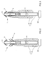
- the first tool 3 especially visible on the Figures 2 and 3 , comprises a bushing 31 and an ejector pusher 32.
- the sleeve 31 is dimensioned to receive the device 1 when this device is introduced by its upstream end 111.
- the sleeve 31 is further dimensioned to house this device 1, with the exception of its cup seal 13, in a configuration in which the elastic tabs 14 are in the folded position towards the hollow body 11.
- the pusher 32 which is advantageously provided with a head 320, is slidably mounted with respect to the sleeve 31, which allows it to at least partially eject the device 1 from the sleeve 31 as described later with reference to FIGS. Figures 4 and 5 .
- the second tool 4 is designed to cooperate with the other two tools and will therefore also be described later.
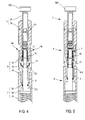
- the third tool comprises a cylinder 51, a centering piston 52, and a prestressed spring 53.
- the centering piston 52 is slidably mounted in the cylinder 51 and biased resiliently by the spring 53 to a rest position in which it partially projects beyond the cylinder 51.
- the centering piston 52 is further dimensioned to constitute, in the rest position, an internal guide to the sleeve 2, this sleeve being able to be introduced into the cylinder 51 as far as an internal stop 511 provided in this cylinder 51.
- the second tool 4 is funnel-shaped and consists of two half-shells 4A and 4B, symmetrical to each other.
- This second tool 4 has an inlet chimney 41, an outlet chimney 43, and an intermediate radial shrinkage zone 42.
- the inlet chimney 41 is dimensioned to receive the lower part of the sleeve 31.
- the outlet chimney 43 is dimensioned to receive at least partially the sheath 2, and to be itself partially introduced into the cylinder 51.
- the radial narrowing zone 42 which connects the inlet chimney 41 to the outlet chimney 43, has, on the side of the outlet chimney 43, a section at most equal to the inner section of the sheath 2.
- the tooling of the invention also preferably comprises a lever 6, a forked support 7, and a frame 81.
- the frame 81 to which the lever 6 and the forked support 7 are connected, may be constituted by a wall of a case 8 which contains in particular the three tools 3, 4, and 5, and possibly cases 10 enclosing each a device 1.
- the lever 6 is rotatably mounted about an axis 60 remote from the frame 81 and advantageously comprises two bearing elements 61 and 62.
- the second support element 62 is spaced apart from the first support element 61 both along the lever 6 and in a direction perpendicular to the lever 6 and its axis of rotation 60, this second support element 62 thus being more away from the frame 81 as the first support element 61.
- the forked support 7 has a fork 71 which is distant from the frame 81 and which extends parallel to the axis 60 of rotation of the lever 6.
- the fork 71 is dimensioned to serve as a support for the sleeve 31 of the first tool 3 while leaving the pusher 32 free, and in particular its head 320 ( figure 8 ).
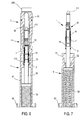
- the third tool 5 is preferably connected to the frame 81, for example by its cylinder 51 or more precisely by the base 50 ( Figures 6 and 7 ) of this cylinder.
- the first support element 61 of the lever 6 is disposed above the fork 71, while the second support element 62 of the lever 6 is disposed above the centering piston 52 of the third tool 5.
- the invention also relates to a method of implementation of the previously described tooling, this method for introducing into the sleeve 2 the flow control device 1 intended to be inserted into a fluid line.
- the first operation of this process consists in introducing, by its upstream end 111, the device 1 in the sleeve 31 of the first tool 3 by applying a force of approach between this sleeve 31 and the downstream end 112 of the device 1, the pusher 32 of the first tool 3 being , either beforehand or during this operation, pushed out of the sleeve 31.
- the third operation of the process consists in inserting the outlet chimney 43 of the second tool 4 into the cylinder 51 of the third tool 5.
- the fourth operation of the process which the Figures 4 and 5 illustrate specifically, consists in inserting, in the inlet chimney 41 of the second tool 4, the sleeve 31 of the first tool 3 by presenting it on the side of the cup seal 13 which protrudes from this sleeve 31.
- This operation has the effect of compressing radially the cup seal 13 in the narrowing zone 42 of the second tool 4 and can optionally begin the introduction of the seal 13 into the sheath 2.
- the fifth process operation consists in gradually returning the pusher 32 of the first tool 3 in the sleeve 31.
- This operation has the effect of partially ejecting the device 1 out of the sleeve 31 by radially compressing the elastic tabs 14 in the narrowing zone 42 of the second tool 4, to fully fit the seal 13 into the sleeve 2, and to also insert the tabs 14 into this sheath 2.
- the method of the invention comprises, before the first operation, a preparatory operation consisting in placing the sleeve 31 of the first tool 3 on the fork 71 of the support 7 while leaving the pusher 32, and in particular its head 320, protruding under the fork 71.
- the approaching force that must be applied between the sleeve 31 and the downstream end 112 of the device 1 can then be exerted ( figure 8 ) by bringing the lever 6 closer to the frame 81 while the first support element 61 is applied to the downstream end 112 of this device 1.
- the fifth operation which consists in gradually returning the pusher 32 of the first tool 3 into the sleeve 31 can be performed ( figure 9 ) by bringing the lever 6 closer to the frame 81 while the second support element 62 is applied to the pusher 32 of the first tool 3.
Landscapes
- Engineering & Computer Science (AREA)
- General Engineering & Computer Science (AREA)
- Mechanical Engineering (AREA)
- Chemical & Material Sciences (AREA)
- Combustion & Propulsion (AREA)
- Automatic Assembly (AREA)
- Shaping Of Tube Ends By Bending Or Straightening (AREA)
- Sampling And Sample Adjustment (AREA)
- Safety Valves (AREA)
- Joints Allowing Movement (AREA)
- Quick-Acting Or Multi-Walled Pipe Joints (AREA)
- Pipe Accessories (AREA)
- Paper (AREA)
- Valves And Accessory Devices For Braking Systems (AREA)
- Electrical Discharge Machining, Electrochemical Machining, And Combined Machining (AREA)
- Nozzles (AREA)
Abstract
Description
- L'invention concerne, de façon générale, les techniques liées à la gestion et à l'exploitation de réseaux de distribution de fluide, et en particulier de gaz.
- Plus précisément, l'invention concerne, selon un premier aspect, un outillage d'introduction d'un dispositif de contrôle d'écoulement dans un fourreau, en vue de l'insertion ultérieure de ce dispositif chemisé par le fourreau dans une canalisation de fluide, ce dispositif de contrôle d'écoulement comprenant un corps creux doté d'une extrémité amont et d'une extrémité aval, une vanne intégrée au corps creux et conçue pour se fermer en réponse à un débit excessif de fluide dans la canalisation, un joint d'étanchéité à coupelle disposé à l'extrémité aval du corps creux, et une pluralité de pattes élastiques liées au corps creux entre les extrémités amont et aval de ce corps creux et conçues pour s'épanouir élastiquement par leurs extrémités libres tournées vers l'extrémité aval du corps creux, une fois le dispositif installé dans la canalisation, le joint et les pattes étant repliés radialement et contraints élastiquement dans le fourreau après introduction de ce dispositif dans ce fourreau.
- Un dispositif de contrôle d'écoulement du type concerné est illustré à la
figure 1 et décrit dans la demande de brevetFR 2007/03767 - Pour pouvoir être mis en place dans une canalisation, les dispositifs de ce type doivent d'abord être partiellement introduits dans un fourreau de contention radiale, comme décrit dans les documents de brevets
FR 2 870 316 FR 2007/03767 - Or, cette opération doit être réalisée avec rigueur et précision de manière à éviter tout endommagement du dispositif de contrôle d'écoulement lors de son introduction dans le fourreau.
- Dans ce contexte, l'invention a pour but de proposer un outillage permettant de réaliser cette opération de façon simple, sûre, et reproductible.
- A cette fin, l'outillage de l'invention, par ailleurs conforme à la définition générique qu'en donne le préambule ci-dessus, est essentiellement caractérisé en ce qu'il comprend au moins trois outils, en ce que le premier outil comprend une douille et un poussoir d'éjection, la douille étant dimensionnée pour recevoir le dispositif de contrôle d'écoulement introduit par son extrémité amont et pour loger, à l'exception du joint à coupelle, ce dispositif de contrôle d'écoulement en position repliée des pattes, le poussoir étant monté coulissant par rapport à la douille pour permettre d'éjecter au moins partiellement le dispositif hors de la douille, en ce que le troisième outil comprend un cylindre et un piston de centrage coulissant dans le cylindre, ce piston de centrage étant sollicité élastiquement par un ressort précontraint vers une position de repos dans laquelle il dépasse partiellement du cylindre, et étant dimensionné pour constituer, en position de repos, un guide interne au fourreau introduit dans le cylindre jusqu'à une butée interne de ce cylindre, en ce que le deuxième outil est conformé en entonnoir et comprend deux demi-coquilles symétriques l'une de l'autre, ce deuxième outil présentant une cheminée d'entrée propre à recevoir au moins partiellement la douille, une cheminée de sortie dimensionnée pour recevoir au moins partiellement le fourreau et pour être partiellement introduite dans le cylindre, et une zone de rétrécissement radial, reliant la cheminée d'entrée à la cheminée de sortie et présentant, du côté de la cheminée de sortie, une section au plus égale à la section interne du fourreau.
- Pour rendre son utilisation plus facile encore, il est possible de prévoir que l'outillage de l'invention comprenne en outre un levier, au moins un support fourchu, et un châssis auquel le levier et le support fourchu sont liés, que le levier soit monté rotatif autour d'un axe distant du châssis et comprenne au moins un premier élément d'appui, que le support fourchu présente une fourche distante du châssis et s'étendant parallèlement à l'axe de rotation du levier, que la fourche soit dimensionnée pour servir d'appui à la douille du premier outil en laissant libre le poussoir, et que le premier élément d'appui du levier soit disposé au-dessus de la fourche.
- Il peut aussi être judicieux de prévoir que le levier comprenne un deuxième élément d'appui espacé du premier élément d'appui à la fois le long du levier et suivant une direction perpendiculaire au levier et à son axe de rotation, le deuxième élément d'appui étant ainsi plus éloigné du châssis que le premier élément d'appui, et de prévoir que le troisième outil soit lié au châssis par son cylindre, et que le deuxième élément d'appui du levier soit disposé au-dessus du piston de centrage du troisième outil.
- Le châssis peut par exemple comprendre une paroi d'une mallette contenant au moins les trois outils.
- L'invention concerne également, selon un deuxième aspect, un procédé de mise en oeuvre de l'outillage tel que précédemment décrit pour introduire dans le fourreau le dispositif de contrôle d'écoulement destiné à être ultérieurement inséré dans une canalisation de fluide, ce procédé étant caractérisé en ce qu'il comprend les opérations consistant à : introduire par son extrémité amont le dispositif dans la douille du premier outil en appliquant une force de rapprochement entre la douille et l'extrémité aval du dispositif, le poussoir de ce premier outil étant ainsi repoussé hors de la douille; placer le fourreau sur le piston de centrage du troisième outil, ce piston étant placé dans sa position de repos; insérer la cheminée de sortie du deuxième outil dans le cylindre du troisième outil; insérer, dans la cheminée d'entrée du deuxième outil, la douille du premier outil en la présentant du côté du joint à coupelle dépassant de cette douille, ce qui a au moins pour effet de comprimer radialement le joint à coupelle dans la zone de rétrécissement du deuxième outil; et rentrer progressivement le poussoir du premier outil dans la douille, ce qui a au moins pour effet d'éjecter partiellement le dispositif hors de la douille en comprimant radialement les pattes élastiques dans la zone de rétrécissement du deuxième outil, de rentrer intégralement le joint dans le fourreau et d'y introduire les pattes tout en repoussant, par l'extrémité aval du dispositif, le piston de centrage dans le cylindre à l'encontre de la force de rappel du ressort précontraint.
- Dans le cas où l'outillage comprend un levier doté d'un premier élément d'appui, le procédé de l'invention comprend de préférence une opération supplémentaire mise en oeuvre avant l'introduction du dispositif dans la douille du premier outil et consistant à placer cette douille sur la fourche en laissant le poussoir dépasser sous la fourche, la force de rapprochement pouvant ainsi être exercée en rapprochant le levier du châssis alors que le premier élément d'appui est appliqué sur l'extrémité aval du dispositif de contrôle d'écoulement.
- Dans le cas où l'outillage comprend un levier doté d'un deuxième élément d'appui, l'opération consistant à rentrer progressivement le poussoir du premier outil dans la douille peut être aisément effectuée en rapprochant le levier du châssis alors que le deuxième élément d'appui est appliqué sur le poussoir du premier outil.
- D'autres caractéristiques et avantages de l'invention ressortiront clairement de la description qui en est faite ci-après, à titre indicatif et nullement limitatif, en référence aux dessins annexés, dans lesquels :
- la
figure 1 est une vue en perspective d'un dispositif de contrôle d'écoulement concerné par l'outillsage de l'invention; - les
figures 2 et 3 sont des vues en coupe axiale représentant l'insertion partielle d'un dispositif de contrôle d'écoulement tel qu'illustré à lafigure 1 dans la douille du premier outil appartenant à l'outillage de l'invention; - les
figures 4 et 5 sont des vues en coupe axiales partielles des trois outils appartenant à l'outillage de l'invention, représentés à des instants successifs de la phase d'insertion d'un dispositif de contrôle d'écoulement tel qu'illustré à lafigure 1 dans un fourreau; - la
figure 6 est une vue en coupe axiale des trois outils appartenant à l'outillage de l'invention, représentés à la fin de la phase d'insertion d'un dispositif de contrôle d'écoulement tel qu'illustré à lafigure 1 dans un fourreau; - la
figure 7 est une vue en coupe axiale du troisième outil représenté postérieurement à la phase d'insertion d'un dispositif de contrôle d'écoulement tel qu'illustré à lafigure 1 dans un fourreau; - la
figure 8 est une vue en perspective représentant un outillage conforme à un mode de réalisation préféré de l'invention, représenté dans une configuration correspondant à l'étape illustrée à lafigure 3 ; et - la
figure 9 est une vue en perspective représentant un outillage conforme au mode de réalisation préféré de l'invention, représenté dans une configuration correspondant à l'étape illustrée à lafigure 6 . - Comme indiqué précédemment, l'invention concerne essentiellement un outillage permettant d'introduire un dispositif de contrôle d'écoulement 1 dans un fourreau 2, cette opération préparant l'insertion ultérieure de ce dispositif, une fois chemisé par le fourreau 2, dans une canalisation de fluide, et en particulier dans une canalisation de gaz.
- Le dispositif de contrôle d'écoulement concerné a été décrit dans la demande de brevet
FR 2007/03767 figure 1 . - Un tel dispositif 1 comprend typiquement un corps creux 11, une vanne 12, un joint d'étanchéité à coupelle 13, et une pluralité de pattes élastiques 14.
- Le corps creux 11 présente une extrémité amont 111 formant un nez d'introduction, et une extrémité aval 112 portant le joint d'étanchéité à coupelle 13.
- La vanne 12, qui est installée dans le corps creux 11, est conçue pour se fermer et corrélativement pour obturer le corps creux lorsque le débit de fluide dans la canalisation excède une valeur limite prédéterminée.
- Le joint d'étanchéité à coupelle 13, qui entoure le corps creux 11 et qui s'applique sur la paroi interne de la canalisation, force le fluide circulant dans la canalisation à traverser le corps creux 11, la circulation de fluide étant ainsi bloquée lorsque la vanne 12 obture le corps creux 11.
- Les pattes élastiques 14, qui sont liées au corps creux 11 entre les extrémités amont 111 et aval 112 de ce corps creux 11, sont conçues pour s'épanouir élastiquement, par leurs extrémités libres 140 tournées vers l'extrémité aval 112 du corps creux 11, une fois le dispositif 1 installé dans la canalisation, et donc pour mainterir ce dispositif en place dans la canalisation.
- Néanmoins, pour pouvoir être inséré dans une canalisation, un tel dispositif 1 doit d'abord être partiellement introduit dans un fourreau 2, le joint 13 et les pattes 14 étant alors repliés radialement et contraints élastiquement dans ce fourreau 2 (
figure 7 ). - A cette fin, l'outillage de l'invention comprend au moins trois outils 3, 4, et 5.
- Le premier outil 3, notamment visible sur les
figures 2 et 3 , comprend une douille 31 et un poussoir d'éjection 32. - Comme le montrent ces figures, la douille 31 est dimensionnée pour recevoir le dispositif 1 lorsque ce dispositif y est introduit par son extrémité amont 111.
- La douille 31 est par ailleurs dimensionnée pour loger ce dispositif 1, à l'exception de son joint à coupelle 13, dans une configuration dans laquelle les pattes élastiques 14 sont en position repliée vers le corps creux 11.
- Le poussoir 32, qui est avantageusement muni d'une tête 320, est monté coulissant par rapport à la douille 31, ce qui lui permet d'éjecter au moins partiellement le dispositif 1 hors de la douille 31 comme décrit ultérieurement en référence aux
figures 4 et 5 . - Le deuxième outil 4 est conçu pour coopérer avec les deux autres outils et sera donc également décrit ultérieurement.
- Le troisième outil 5, partiellement visible aux
figures 4 et 5 et intégralement visible auxfigures 6 et 7 , comprend un cylindre 51, un piston de centrage 52, et un ressort précontraint 53. - Le piston de centrage 52 est monté coulissant dans le cylindre 51 et sollicité élastiquement par le ressort 53 vers une position de repos dans laquelle il dépasse partiellement du cylindre 51.
- Comme le suggère notamment la
figure 4 , le piston de centrage 52 est par ailleurs dimensionné pour constituer, en position de repos, un guide interne au fourreau 2, ce fourreau pouvant être introduit dans le cylindre 51 jusqu'à une butée interne 511 prévue dans ce cylindre 51. - Le deuxième outil 4 est conformé en entonnoir et est constitué de deux demi-coquilles 4A et 4B, symétriques l'une de l'autre.
- Ce deuxième outil 4 présente une cheminée d'entrée 41, une cheminée de sortie 43, et une zone intermédiaire de rétrécissement radial 42.
- La cheminée d'entrée 41 est dimensionnée pour recevoir la partie inférieure de la douille 31.
- La cheminée de sortie 43 est dimensionnée pour recevoir au moins partiellement le fourreau 2, et pour être elle-même partiellement introduite dans le cylindre 51.
- Et la zone de rétrécissement radial 42, qui relie la cheminée d'entrée 41 à la cheminée de sortie 43, présente, du côté de la cheminée de sortie 43, une section au plus égale à la section interne du fourreau 2.
- Comme le montrent les
figures 8 et 9 , l'outillage de l'invention comprend aussi de préférence un levier 6, un support fourchu 7, et un châssis 81. - En fait, le châssis 81, auquel le levier 6 et le support fourchu 7 sont liés, peut être constitué par une paroi d'une mallette 8 qui contient notamment les trois outils 3, 4, et 5, et éventuellement des étuis 10 renfermant chacun un dispositif 1.
- Le levier 6 est monté rotatif autour d'un axe 60 distant du châssis 81 et comprend avantageusement deux éléments d'appui 61 et 62.
- Le deuxième élément d'appui 62 est espacé du premier élément d'appui 61 à la fois le long du levier 6 et suivant une direction perpendiculaire au levier 6 et à son axe de rotation 60, ce deuxième élément d'appui 62 étant ainsi plus éloigné du châssis 81 que le premier élément d'appui 61.
- Le support fourchu 7 présente une fourche 71 qui est distante du châssis 81 et qui s'étend parallèlement à l'axe 60 de rotation du levier 6.
- La fourche 71 est dimensionnée pour servir d'appui à la douille 31 du premier outil 3 en laissant libre le poussoir 32, et notamment sa tête 320 (
figure 8 ). - Comme le suggèrent les
figures 8 et 9 , le troisième outil 5 est de préférence lié au châssis 81, par exemple par son cylindre 51 ou plus précisément par l'embase 50 (figures 6 et 7 ) de ce cylindre. - Le premier élément d'appui 61 du levier 6 est disposé au-dessus de la fourche 71, tandis que le deuxième élément d'appui 62 du levier 6 est disposé au-dessus du piston de centrage 52 du troisième outil 5.
- L'invention concerne également un procédé de mise en oeuvre de l'outillage précédemment décrit, ce procédé permettant d'introduire dans le fourreau 2 le dispositif 1 de contrôle d'écoulement destiné à être inséré dans une canalisation de fluide.
- La première opération de ce procédé, illustrée aux
figures 2 et 3 , consiste à introduire, par son extrémité amont 111, le dispositif 1 dans la douille 31 du premier outil 3 en appliquant une force de rapprochement entre cette douille 31 et l'extrémité aval 112 du dispositif 1, le poussoir 32 du premier outil 3 étant, soit de façon préalable, soit pendant cette opération, repoussé hors de la douille 31. - La deuxième opération de ce procédé, qui est suggérée aux
figures 4 et 5 qui en illustrent le résultat, consiste à placer le fourreau 2 sur le piston de centrage 52 du troisième outil 5, ce piston 52 étant alors placé dans sa position de repos. - La troisième opération du procédé, également suggérée aux
figures 4 et 5 et préalable à l'état illustré sur ces figures, consiste à insérer la cheminée de sortie 43 du deuxième outil 4 dans le cylindre 51 du troisième outil 5. - La quatrième opération du procédé, que les
figures 4 et 5 illustrent de façon spécifique, consiste à insérer, dans la cheminée d'entrée 41 du deuxième outil 4, la douille 31 du premier outil 3 en la présentant du côté du joint à coupelle 13 qui dépasse de cette douille 31. - Cette opération a notamment pour effet de comprimer radialement le joint à coupelle 13 dans la zone de rétrécissement 42 du deuxième outil 4 et peut éventuellement commencer l'introduction du joint 13 dans le fourreau 2.
- La cinquième opération du procédé, dont le résultat est visible sur la
figure 6 , consiste à rentrer progressivement le poussoir 32 du premier outil 3 dans la douille 31. - Cette opération a notamment pour effet d'éjecter partiellement le dispositif 1 hors de la douille 31 en comprimant radialement les pattes élastiques 14 dans la zone de rétrécissement 42 du deuxième outil 4, de rentrer intégralement le joint 13 dans le fourreau 2, et d'introduire également les pattes 14 dans ce fourreau 2.
- En outre, pendant cette opération, l'extrémité aval 112 du dispositif 1 repousse le piston de centrage 52 dans le cylindre 51 à l'encontre de la force de rappel exercée par le ressort précontraint 53.
- Dans le cas préféré où l'outillage de l'invention comprend notamment le levier 6 et le support fourchu 7 tels qu'illustrés aux
figures 8 et 9 , le procédé de l'invention comprend, avant la première opération, une opération préparatoire consistant à placer la douille 31 du premier outil 3 sur la fourche 71 du support 7 en laissant le poussoir 32, et notamment sa tête 320, dépasser sous la fourche 71. - La force de rapprochement qui doit être appliquée entre la douille 31 et l'extrémité aval 112 du dispositif 1 peut alors être exercée (
figure 8 ) en rapprochant le levier 6 du châssis 81 pendant que le premier élément d'appui 61 est appliqué sur l'extrémité aval 112 de ce dispositif 1. - Par ailleurs, la cinquième opération, qui consiste à rentrer progressivement le poussoir 32 du premier outil 3 dans la douille 31 peut être effectuée (
figure 9 ) en rapprochant le levier 6 du châssis 81 alors que le deuxième élément d'appui 62 est appliqué sur le poussoir 32 du premier outil 3.
Claims (7)
- Outillage d'introduction d'un dispositif de contrôle d'écoulement (1) dans un fourreau (2), en vue de l'insertion ultérieure de ce dispositif chemisé par le fourreau dans une canalisation de fluide, ce dispositif de contrôle d'écoulement (1) comprenant un corps creux (11) doté d'une extrémité amont (111) et d'une extrémité aval (112), une vanne (12) intégrée au corps creux (11) et conçue pour se fermer en réponse à un débit excessif de fluide dans la canalisation, un joint d'étanchéité à coupelle (13) disposé à l'extrémité aval (112) du corps creux (11), et une pluralité de pattes élastiques (14) liées au corps creux (11) entre les extrémités amont (111) et aval (112) de ce corps creux (11) et conçues pour s'épanouir élastiquement par leurs extrémités libres tournées vers l'extrémité aval (112) du corps creux (11), une fois le dispositif (1) installé dans la canalisation, le joint (13) et les pattes (14) étant repliés radialement et contraints élastiquement dans le fourreau (2) après introduction de ce dispositif (1) dans ce fourreau (2), et cet outillage étant caractérisé en ce qu'il comprend au moins trois outils (3, 4, 5), en ce que le premier outil (3) comprend une douille (31) et un poussoir d'éjection (32), la douille (31) étant dimensionnée pour recevoir le dispositif de contrôle d'écoulement (1) introduit par son extrémité amont (111) et pour loger, à l'exception du joint à coupelle (13), ce dispositif de contrôle d'écoulement en position repliée des pattes (14), le poussoir (32) étant monté coulissant par rapport à la douille (31) pour permettre d'éjecter au moins partiellement le dispositif (1) hors de la douille (31), en ce que le troisième outil (5) comprend un cylindre (51) et un piston de centrage (52) coulissant dans le cylindre (51), ce piston de centrage (52) étant sollicité élastiquement par un ressort précontraint (53) vers une position de repos dans laquelle il dépasse partiellement du cylindre (51), et étant dimensionné pour constituer, en position de repos, un guide interne au fourreau (2) introduit dans le cylindre (51) jusqu'à une butée interne (511) de ce cylindre (51), en ce que le deuxième outil (4) est conformé en entonnoir et comprend deux demi-coquilles (4A, 4B) symétriques l'une de l'autre, ce deuxième outil (4) présentant une cheminée d'entrée (41) propre à recevoir au moins partiellement la douille (31), une cheminée de sortie (43) dimensionnée pour recevoir au moins partiellement le fourreau (2) et pour être partiellement introduite dans le cylindre (51), et une zone de rétrécissement radial (42), reliant la cheminée d'entrée (41) à la cheminée de sortie (43) et présentant, du côté de la cheminée de sortie (43), une section au plus égale à la section interne du fourreau (2).
- Outillage suivant la revendication 1, caractérisé en ce qu'il comprend en outre un levier (6), au moins un support fourchu (7), et un châssis (81) auquel le levier (6) et le support fourchu (7) sont liés, en ce que le levier (6) est monté rotatif autour d'un axe (60) distant du châssis (81) et comprend au moins un premier élément d'appui (61), en ce que le support fourchu (7) présente une fourche (71) distante du châssis (81) et s'étendant parallèlement à l'axe (60) de rotation du levier (6), en ce que la fourche (71) est dimensionnée pour servir d'appui à la douille (31) du premier outil (3) en laissant libre le poussoir (32), et en ce que le premier élément d'appui (61) du levier (6) est disposé au-dessus de la fourche (71).
- Outillage suivant la revendication 2,
caractérisé en ce que le levier (6) comprend un deuxième élément d'appui (62) espacé du premier élément d'appui (61) à la fois le long du levier (6) et suivant une direction perpendiculaire au levier (6) et à son axe de rotation (60), le deuxième élément d'appui (62) étant ainsi plus éloigné du châssis (81) que le premier élément d'appui (61), en ce que le troisième outil (5) est lié au châssis (81) par son cylindre (51), et en ce que le deuxième élément d'appui (62) du levier (6) est disposé au-dessus du piston de centrage (52) du troisième outil (5). - Outillage suivant l'une quelconque des revendications 2 et 3, caractérisé en ce que le châssis (81) comprend une paroi d'une mallette (8) contenant au moins les trois outils (3, 4, 5).
- Procédé de mise en oeuvre de l'outillage suivant l'une quelconque des revendications précédentes pour introduire dans le fourreau (2) le dispositif (1) de contrôle d'écoulement destiné à être inséré dans une canalisation de fluide, caractérisé en ce qu'il comprend les opérations consistant à : introduire par son extrémité amont (111) le dispositif (1) dans la douille (31) du premier outil (3) en appliquant une force de rapprochement entre la douille (31) et l'extrémité aval (112) du dispositif (1), le poussoir (32) de ce premier outil (3) étant ainsi repoussé hors de la douille (31); placer le fourreau (2) sur le piston de centrage (52) du troisième outil (5), ce piston (52) étant placé dans sa position de repos; insérer la cheminée de sortie (43) du deuxième outil (4) dans le cylindre (51) du troisième outil (5); insérer, dans la cheminée d'entrée (41) du deuxième outil (4), la douille (31) du premier outil (3) en la présentant du côté du joint à coupelle (13) dépassant de cette douille (31), ce qui a au moins pour effet de comprimer radialement le joint à coupelle (13) dans la zone de rétrécissement (42) du deuxième outil (4); et rentrer progressivement le poussoir (32) du premier outil (3) dans la douille (31), ce qui a au moins pour effet d'éjecter partiellement le dispositif (1) hors de la douille (31) en comprimant radialement les pattes élastiques (14) dans la zone de rétrécissement (42) du deuxième outil (4), de rentrer intégralement le joint (13) dans le fourreau (2) et d'y introduire les pattes (14) tout en repoussant, par l'extrémité aval (112) du dispositif (1), le piston de centrage (52) dans le cylindre (51) à l'encontre de la force de rappel du ressort précontraint (53).
- Procédé suivant la revendication 5, pour la mise en oeuvre de l'outillage suivant la revendication 2, caractérisé en ce qu'il comprend l'opération supplémentaire mise en oeuvre avant l'introduction du dispositif (1) dans la douille (31) du premier outil (3) et consistant à placer cette douille (31) sur la fourche (71) en laissant le poussoir (32) dépasser sous la fourche (71), et en ce que la force de rapprochement est exercée en rapprochant le levier (6) du châssis (81) alors que le premier élément d'appui (61) est appliqué sur l'extrémité aval (112) du dispositif (1) de contrôle d'écoulement.
- Procédé suivant l'une quelconque des revendications 5 et 6, pour la mise en oeuvre de l'outillage suivant la revendication 3, caractérisé en ce que l'opération consistant à rentrer progressivement le poussoir (32) du premier outil (3) dans la douille (31) est effectuée en rapprochant le levier (6) du châssis (81) alors que le deuxième élément d'appui (62) est appliqué sur le poussoir (32) du premier outil (3).
Priority Applications (1)
| Application Number | Priority Date | Filing Date | Title |
|---|---|---|---|
| SI200930004T SI2123962T1 (sl) | 2008-05-20 | 2009-04-24 | Set orodij za uvajanje v stročnico naprave za krmiljenje pretoka v vod za tekočino in postopek uporabe |
Applications Claiming Priority (1)
| Application Number | Priority Date | Filing Date | Title |
|---|---|---|---|
| FR0853279A FR2931531B1 (fr) | 2008-05-20 | 2008-05-20 | Outillage d'introduction dans un fourreau d'un dispositif de controle d'ecoulement pour une canalisation de fluide, et procede de mise en oeuvre |
Publications (2)
| Publication Number | Publication Date |
|---|---|
| EP2123962A1 true EP2123962A1 (fr) | 2009-11-25 |
| EP2123962B1 EP2123962B1 (fr) | 2010-06-09 |
Family
ID=40119330
Family Applications (1)
| Application Number | Title | Priority Date | Filing Date |
|---|---|---|---|
| EP20090158728 Active EP2123962B1 (fr) | 2008-05-20 | 2009-04-24 | Outillage d'introduction dans un fourreau d'un dispositif de contrôle d'écoulement pour une canalisation de fluide, et procédé de mise en oeuvre |
Country Status (11)
| Country | Link |
|---|---|
| US (1) | US8272112B2 (fr) |
| EP (1) | EP2123962B1 (fr) |
| JP (1) | JP5536363B2 (fr) |
| AT (1) | ATE470817T1 (fr) |
| CA (1) | CA2666252C (fr) |
| DE (1) | DE602009000037D1 (fr) |
| DK (1) | DK2123962T3 (fr) |
| ES (1) | ES2344820T3 (fr) |
| FR (1) | FR2931531B1 (fr) |
| PT (1) | PT2123962E (fr) |
| SI (1) | SI2123962T1 (fr) |
Cited By (4)
| Publication number | Priority date | Publication date | Assignee | Title |
|---|---|---|---|---|
| ES2440084R1 (es) * | 2009-12-07 | 2014-03-21 | Lyonnaise Des Eaux France | Dispositivo de conexión a una red de distribución de agua y procedimiento de instalación y utilización del mismo |
| WO2026082926A1 (fr) * | 2024-10-17 | 2026-04-23 | Natran | Dispositif de positionnement dans une canalisation de fluide et dispositif d'arrêt d'un débit de fuite le comportant |
| WO2026082930A1 (fr) * | 2024-10-17 | 2026-04-23 | Natran | Dispositif de positionnement dans une canalisation de fluide et dispositif d'arrêt d'un débit de fuite le comportant |
| FR3167685A1 (fr) * | 2024-10-17 | 2026-04-24 | Grtgaz | Dispositif de positionnement dans une canalisation de fluide et dispositif d’arrêt d’un débit de fuite le comportant |
Families Citing this family (5)
| Publication number | Priority date | Publication date | Assignee | Title |
|---|---|---|---|---|
| GB2452867B (en) * | 2008-10-17 | 2009-08-05 | Cambridge Reactor Design Ltd | A valve assembly |
| FR3011060B1 (fr) | 2013-09-24 | 2015-10-16 | Grdf | Dispositif de controle inserable dans une canalisation; |
| USD1118355S1 (en) * | 2024-05-21 | 2026-03-17 | Qianbin Ma | Cleaning tool set |
| WO2026082929A1 (fr) * | 2024-10-17 | 2026-04-23 | Natran | Dispositif de positionnement dans une canalisation de fluide et dispositif d'arrêt d'un débit de fuite le comportant |
| FR3167687A1 (fr) * | 2024-10-17 | 2026-04-24 | Grtgaz | Dispositif de positionnement dans une canalisation de fluide et dispositif d’arrêt d’un débit de fuite le comportant |
Citations (3)
| Publication number | Priority date | Publication date | Assignee | Title |
|---|---|---|---|---|
| GB2196715A (en) * | 1986-10-27 | 1988-05-05 | British Gas Plc | Method of launching a pig into a pipeline |
| GB2244780A (en) * | 1990-05-16 | 1991-12-11 | Phoenix Inspection Systems Lim | A method and system for delivering an expansionary head |
| FR2870316A1 (fr) | 2004-05-11 | 2005-11-18 | Gaz De France | Dispositif inserable dans une canalisation, a capacite accrue de maintien en place |
Family Cites Families (9)
| Publication number | Priority date | Publication date | Assignee | Title |
|---|---|---|---|---|
| US3898918A (en) * | 1969-05-13 | 1975-08-12 | Carter Warne Jun | Device for temporarily providing a seal within an advancing pipe |
| JPS638481U (fr) * | 1986-07-01 | 1988-01-20 | ||
| AP43A (en) * | 1986-11-12 | 1989-07-16 | Silkbell Ltd | "Flow regulating device." |
| US4958657A (en) * | 1989-05-11 | 1990-09-25 | Umac Incorporated | Gas supply safety device |
| GB2299645B (en) * | 1995-04-04 | 1999-04-07 | British Gas Plc | Installing pipes |
| FR2794842B1 (fr) * | 1999-06-10 | 2001-09-28 | Gaz De France | Dispositif de securite universel et procede de protection d'une canalisation |
| FR2843437B1 (fr) * | 2002-08-09 | 2004-09-24 | Gaz De France | Dispositif de securite a declenchement automatique et a clapet double pour controler le debit d'un fluide |
| FR2916511B1 (fr) * | 2007-05-25 | 2009-07-17 | Gaz De France Sa | Dispositif de securite compact a declenchement automatique pour controler le debit d'un fluide. |
| FR2931530B1 (fr) * | 2008-05-20 | 2010-06-11 | Gaz De France | Outillage d'insertion d'un dispositif de controle d'ecoulement dans une canalisation fluide, et procede de mise en oeuvre |
-
2008
- 2008-05-20 FR FR0853279A patent/FR2931531B1/fr not_active Expired - Fee Related
-
2009
- 2009-04-24 ES ES09158728T patent/ES2344820T3/es active Active
- 2009-04-24 EP EP20090158728 patent/EP2123962B1/fr active Active
- 2009-04-24 PT PT09158728T patent/PT2123962E/pt unknown
- 2009-04-24 DK DK09158728T patent/DK2123962T3/da active
- 2009-04-24 AT AT09158728T patent/ATE470817T1/de active
- 2009-04-24 SI SI200930004T patent/SI2123962T1/sl unknown
- 2009-04-24 DE DE200960000037 patent/DE602009000037D1/de active Active
- 2009-05-15 US US12/466,567 patent/US8272112B2/en active Active
- 2009-05-19 JP JP2009120791A patent/JP5536363B2/ja not_active Expired - Fee Related
- 2009-05-20 CA CA2666252A patent/CA2666252C/fr active Active
Patent Citations (3)
| Publication number | Priority date | Publication date | Assignee | Title |
|---|---|---|---|---|
| GB2196715A (en) * | 1986-10-27 | 1988-05-05 | British Gas Plc | Method of launching a pig into a pipeline |
| GB2244780A (en) * | 1990-05-16 | 1991-12-11 | Phoenix Inspection Systems Lim | A method and system for delivering an expansionary head |
| FR2870316A1 (fr) | 2004-05-11 | 2005-11-18 | Gaz De France | Dispositif inserable dans une canalisation, a capacite accrue de maintien en place |
Cited By (5)
| Publication number | Priority date | Publication date | Assignee | Title |
|---|---|---|---|---|
| ES2440084R1 (es) * | 2009-12-07 | 2014-03-21 | Lyonnaise Des Eaux France | Dispositivo de conexión a una red de distribución de agua y procedimiento de instalación y utilización del mismo |
| WO2026082926A1 (fr) * | 2024-10-17 | 2026-04-23 | Natran | Dispositif de positionnement dans une canalisation de fluide et dispositif d'arrêt d'un débit de fuite le comportant |
| WO2026082930A1 (fr) * | 2024-10-17 | 2026-04-23 | Natran | Dispositif de positionnement dans une canalisation de fluide et dispositif d'arrêt d'un débit de fuite le comportant |
| FR3167686A1 (fr) * | 2024-10-17 | 2026-04-24 | Grtgaz | Dispositif de positionnement dans une canalisation de fluide et dispositif d’arrêt d’un débit de fuite le comportant |
| FR3167685A1 (fr) * | 2024-10-17 | 2026-04-24 | Grtgaz | Dispositif de positionnement dans une canalisation de fluide et dispositif d’arrêt d’un débit de fuite le comportant |
Also Published As
| Publication number | Publication date |
|---|---|
| DK2123962T3 (da) | 2010-10-11 |
| PT2123962E (pt) | 2010-07-15 |
| US20100000068A1 (en) | 2010-01-07 |
| EP2123962B1 (fr) | 2010-06-09 |
| ATE470817T1 (de) | 2010-06-15 |
| SI2123962T1 (sl) | 2010-09-30 |
| US8272112B2 (en) | 2012-09-25 |
| CA2666252A1 (fr) | 2009-11-20 |
| ES2344820T3 (es) | 2010-09-07 |
| JP2010032041A (ja) | 2010-02-12 |
| DE602009000037D1 (de) | 2010-07-22 |
| CA2666252C (fr) | 2016-07-19 |
| JP5536363B2 (ja) | 2014-07-02 |
| FR2931531A1 (fr) | 2009-11-27 |
| FR2931531B1 (fr) | 2010-06-11 |
Similar Documents
| Publication | Publication Date | Title |
|---|---|---|
| EP2123962B1 (fr) | Outillage d'introduction dans un fourreau d'un dispositif de contrôle d'écoulement pour une canalisation de fluide, et procédé de mise en oeuvre | |
| WO2008025899A1 (fr) | Vanne thermostatique destinee a etre interposee entre un reservoir de carburant et un moteur thermique, et circuit de circulation de carburant correspondant | |
| FR2843624A1 (fr) | Dispositif de branchement d'alimentation pour un systeme a pression de fluide | |
| CA2666257C (fr) | Outillage d'insertion d'un dispositif de controle d'ecoulement pour une canalisation de fluide, et procede de mise en oeuvre | |
| FR3022480A1 (fr) | Machine pour sertir un bossage de chambre de combustion. | |
| EP3071856B1 (fr) | Agencement pour le montage en aveugle d'un câble de frein par emboîtement élastique dans un élément de butée | |
| EP3160682B1 (fr) | Ensemble pour chambre de combustion de turbomachine comprenant un bossage et un élément annulaire | |
| CA3041665A1 (fr) | Circuit de fluide comprenant une premiere canalisation, une deuxieme canalisation et un raccord de liaison et procede de raccordement | |
| FR2726208A1 (fr) | Procede de retreint | |
| EP2426455B1 (fr) | Procédé de compression d'un matériau explosif dans un corps de projectile et outillage permettant la mise en oeuvre d'un tel procédé | |
| EP1985906B1 (fr) | Adaptateur de test ou de remplissage de recipient ou circuit de fluide avec un goulot | |
| WO2014106609A1 (fr) | Raccord pour circuit de fibres optiques et procede de connexion d'un tel circuit a un tel raccord | |
| EP1596120A1 (fr) | Dispositif insérable dans une canalisation, à capacité accrue de maintien en place | |
| EP3601025B1 (fr) | Luge de preparation et procede d'assemblage pour un vehicule | |
| WO2011114077A2 (fr) | Obturateur pour conduit de fluide de réacteur nucléaire, notamment pour drain de fond de générateur de vapeur | |
| FR3080902A1 (fr) | Cartouche de raccordement a insertion rapide et verrouillable | |
| FR2565646A1 (fr) | Frein a disque | |
| FR2916389A1 (fr) | Dispositif de securite pour conduit de remplissage de carburant pour vehicule automobile. | |
| EP1349760B1 (fr) | Piston de maitre-cylindre et dispositif de montage d'un clapet dans ce piston | |
| CA2588578A1 (fr) | Procede de fixation d'un arbre de transmission flexible dans un inverseur de poussee et un tel inverseur de poussee | |
| FR3067297B1 (fr) | Dispositif d’inhibition d’un detrompeur de reservoir | |
| FR2927134A1 (fr) | Dispositif de raccordement d'une piece male dans une piece femelle par l'intermediaire d'une piece de blocage axial de la piece male dans la piece femelle | |
| FR3039246A1 (fr) | Systeme et procede d'introduction d'un traceur dans une canalisation | |
| FR3094766A1 (fr) | Outil de demontage manuel d’un dispositif de commande a pedale | |
| WO2013072588A1 (fr) | Outil de demontage du plongeur d'un filtre a huile |
Legal Events
| Date | Code | Title | Description |
|---|---|---|---|
| PUAI | Public reference made under article 153(3) epc to a published international application that has entered the european phase |
Free format text: ORIGINAL CODE: 0009012 |
|
| 17P | Request for examination filed |
Effective date: 20090925 |
|
| AK | Designated contracting states |
Kind code of ref document: A1 Designated state(s): AT BE BG CH CY CZ DE DK EE ES FI FR GB GR HR HU IE IS IT LI LT LU LV MC MK MT NL NO PL PT RO SE SI SK TR |
|
| GRAP | Despatch of communication of intention to grant a patent |
Free format text: ORIGINAL CODE: EPIDOSNIGR1 |
|
| GRAS | Grant fee paid |
Free format text: ORIGINAL CODE: EPIDOSNIGR3 |
|
| GRAA | (expected) grant |
Free format text: ORIGINAL CODE: 0009210 |
|
| AK | Designated contracting states |
Kind code of ref document: B1 Designated state(s): AT BE BG CH CY CZ DE DK EE ES FI FR GB GR HR HU IE IS IT LI LT LU LV MC MK MT NL NO PL PT RO SE SI SK TR |
|
| REG | Reference to a national code |
Ref country code: CH Ref legal event code: EP |
|
| REG | Reference to a national code |
Ref country code: IE Ref legal event code: FG4D Free format text: LANGUAGE OF EP DOCUMENT: FRENCH |
|
| REG | Reference to a national code |
Ref country code: CH Ref legal event code: NV Representative=s name: NOVAGRAAF SWITZERLAND S.A. Ref country code: PT Ref legal event code: SC4A Free format text: AVAILABILITY OF NATIONAL TRANSLATION Effective date: 20100611 |
|
| REF | Corresponds to: |
Ref document number: 602009000037 Country of ref document: DE Date of ref document: 20100722 Kind code of ref document: P |
|
| REG | Reference to a national code |
Ref country code: NL Ref legal event code: T3 |
|
| REG | Reference to a national code |
Ref country code: RO Ref legal event code: EPE |
|
| REG | Reference to a national code |
Ref country code: ES Ref legal event code: FG2A Ref document number: 2344820 Country of ref document: ES Kind code of ref document: T3 |
|
| REG | Reference to a national code |
Ref country code: DK Ref legal event code: T3 |
|
| PG25 | Lapsed in a contracting state [announced via postgrant information from national office to epo] |
Ref country code: NO Free format text: LAPSE BECAUSE OF FAILURE TO SUBMIT A TRANSLATION OF THE DESCRIPTION OR TO PAY THE FEE WITHIN THE PRESCRIBED TIME-LIMIT Effective date: 20100909 Ref country code: SE Free format text: LAPSE BECAUSE OF FAILURE TO SUBMIT A TRANSLATION OF THE DESCRIPTION OR TO PAY THE FEE WITHIN THE PRESCRIBED TIME-LIMIT Effective date: 20100609 Ref country code: LT Free format text: LAPSE BECAUSE OF FAILURE TO SUBMIT A TRANSLATION OF THE DESCRIPTION OR TO PAY THE FEE WITHIN THE PRESCRIBED TIME-LIMIT Effective date: 20100609 |
|
| LTIE | Lt: invalidation of european patent or patent extension |
Effective date: 20100609 |
|
| PG25 | Lapsed in a contracting state [announced via postgrant information from national office to epo] |
Ref country code: LV Free format text: LAPSE BECAUSE OF FAILURE TO SUBMIT A TRANSLATION OF THE DESCRIPTION OR TO PAY THE FEE WITHIN THE PRESCRIBED TIME-LIMIT Effective date: 20100609 Ref country code: HR Free format text: LAPSE BECAUSE OF FAILURE TO SUBMIT A TRANSLATION OF THE DESCRIPTION OR TO PAY THE FEE WITHIN THE PRESCRIBED TIME-LIMIT Effective date: 20100609 Ref country code: FI Free format text: LAPSE BECAUSE OF FAILURE TO SUBMIT A TRANSLATION OF THE DESCRIPTION OR TO PAY THE FEE WITHIN THE PRESCRIBED TIME-LIMIT Effective date: 20100609 |
|
| REG | Reference to a national code |
Ref country code: SK Ref legal event code: T3 Ref document number: E 7882 Country of ref document: SK |
|
| PG25 | Lapsed in a contracting state [announced via postgrant information from national office to epo] |
Ref country code: CY Free format text: LAPSE BECAUSE OF FAILURE TO SUBMIT A TRANSLATION OF THE DESCRIPTION OR TO PAY THE FEE WITHIN THE PRESCRIBED TIME-LIMIT Effective date: 20100616 Ref country code: PL Free format text: LAPSE BECAUSE OF FAILURE TO SUBMIT A TRANSLATION OF THE DESCRIPTION OR TO PAY THE FEE WITHIN THE PRESCRIBED TIME-LIMIT Effective date: 20100609 |
|
| REG | Reference to a national code |
Ref country code: HU Ref legal event code: AG4A Ref document number: E008773 Country of ref document: HU |
|
| PG25 | Lapsed in a contracting state [announced via postgrant information from national office to epo] |
Ref country code: EE Free format text: LAPSE BECAUSE OF FAILURE TO SUBMIT A TRANSLATION OF THE DESCRIPTION OR TO PAY THE FEE WITHIN THE PRESCRIBED TIME-LIMIT Effective date: 20100609 |
|
| PG25 | Lapsed in a contracting state [announced via postgrant information from national office to epo] |
Ref country code: IS Free format text: LAPSE BECAUSE OF FAILURE TO SUBMIT A TRANSLATION OF THE DESCRIPTION OR TO PAY THE FEE WITHIN THE PRESCRIBED TIME-LIMIT Effective date: 20101009 |
|
| PLBE | No opposition filed within time limit |
Free format text: ORIGINAL CODE: 0009261 |
|
| STAA | Information on the status of an ep patent application or granted ep patent |
Free format text: STATUS: NO OPPOSITION FILED WITHIN TIME LIMIT |
|
| PG25 | Lapsed in a contracting state [announced via postgrant information from national office to epo] |
Ref country code: GR Free format text: LAPSE BECAUSE OF FAILURE TO SUBMIT A TRANSLATION OF THE DESCRIPTION OR TO PAY THE FEE WITHIN THE PRESCRIBED TIME-LIMIT Effective date: 20100910 |
|
| REG | Reference to a national code |
Ref country code: DE Ref legal event code: R097 Ref document number: 602009000037 Country of ref document: DE Effective date: 20110309 |
|
| REG | Reference to a national code |
Ref country code: CH Ref legal event code: PCAR Free format text: NOVAGRAAF SWITZERLAND SA;CHEMIN DE L'ECHO 3;1213 ONEX (CH) |
|
| PG25 | Lapsed in a contracting state [announced via postgrant information from national office to epo] |
Ref country code: MT Free format text: LAPSE BECAUSE OF FAILURE TO SUBMIT A TRANSLATION OF THE DESCRIPTION OR TO PAY THE FEE WITHIN THE PRESCRIBED TIME-LIMIT Effective date: 20100609 |
|
| PG25 | Lapsed in a contracting state [announced via postgrant information from national office to epo] |
Ref country code: BG Free format text: LAPSE BECAUSE OF FAILURE TO SUBMIT A TRANSLATION OF THE DESCRIPTION OR TO PAY THE FEE WITHIN THE PRESCRIBED TIME-LIMIT Effective date: 20100909 |
|
| REG | Reference to a national code |
Ref country code: FR Ref legal event code: PLFP Year of fee payment: 8 |
|
| REG | Reference to a national code |
Ref country code: FR Ref legal event code: PLFP Year of fee payment: 9 |
|
| REG | Reference to a national code |
Ref country code: FR Ref legal event code: PLFP Year of fee payment: 10 |
|
| REG | Reference to a national code |
Ref country code: LU Ref legal event code: HC Owner name: ENGIE; FR Free format text: FORMER OWNER: GDF SUEZ Effective date: 20190118 Ref country code: LU Ref legal event code: HC Owner name: GDF SUEZ; FR Free format text: FORMER OWNER: GDF SUEZ Effective date: 20190118 Ref country code: LU Ref legal event code: PD Owner name: GRTGAZ; FR Free format text: FORMER OWNER: ENGIE Effective date: 20190118 |
|
| REG | Reference to a national code |
Ref country code: GB Ref legal event code: 732E Free format text: REGISTERED BETWEEN 20190131 AND 20190206 |
|
| REG | Reference to a national code |
Ref country code: CH Ref legal event code: PFA Owner name: ENGIE, FR Free format text: FORMER OWNER: GDF SUEZ, FR Ref country code: CH Ref legal event code: PUE Owner name: GRTGAZ, FR Free format text: FORMER OWNER: ENGIE, FR |
|
| REG | Reference to a national code |
Ref country code: BE Ref legal event code: HC Owner name: ENGIE; FR Free format text: DETAILS ASSIGNMENT: CHANGE OF OWNER(S), CHANGEMENT DE NOM DU PROPRIETAIRE Effective date: 20190129 Ref country code: BE Ref legal event code: PD Owner name: GRTGAZ; FR Free format text: DETAILS ASSIGNMENT: CHANGE OF OWNER(S), CESSION Effective date: 20190129 |
|
| REG | Reference to a national code |
Ref country code: NL Ref legal event code: HC Owner name: ENGIE; FR Free format text: DETAILS ASSIGNMENT: CHANGE OF OWNER(S), CHANGE OF OWNER(S) NAME; FORMER OWNER NAME: GDF SUEZ Effective date: 20190320 Ref country code: NL Ref legal event code: PD Owner name: GRTGAZ; FR Free format text: DETAILS ASSIGNMENT: CHANGE OF OWNER(S), ASSIGNMENT; FORMER OWNER NAME: ENGIE Effective date: 20190320 |
|
| REG | Reference to a national code |
Ref country code: SK Ref legal event code: PC4A Ref document number: E 7882 Country of ref document: SK Owner name: GRTGAZ, S.A., BOIS-COLOMBES, FR Free format text: FORMER OWNER: ENGIE S.A., COURBEVOIE, FR Effective date: 20190503 Ref country code: SK Ref legal event code: TC4A Ref document number: E 7882 Country of ref document: SK Owner name: ENGIE S.A., COURBEVOIE, FR Effective date: 20190503 |
|
| REG | Reference to a national code |
Ref country code: ES Ref legal event code: PC2A Owner name: GRTGAZ Effective date: 20190823 |
|
| REG | Reference to a national code |
Ref country code: HU Ref legal event code: FH1C Free format text: FORMER REPRESENTATIVE(S): SIPOS JOZSEF, DANUBIA SZABADALMI ES JOGI IRODA KFT., HU Representative=s name: DR. KOCSOMBA NELLI UEGYVEDI IRODA, HU Ref country code: HU Ref legal event code: GB9C Owner name: GRTGAZ, FR Free format text: FORMER OWNER(S): GDF SUEZ, FR; ENGIE, FR Ref country code: HU Ref legal event code: HC9C Owner name: GRTGAZ, FR Free format text: FORMER OWNER(S): GDF SUEZ, FR; ENGIE, FR |
|
| REG | Reference to a national code |
Ref country code: HU Ref legal event code: HC9C Owner name: GRTGAZ, FR Free format text: FORMER OWNER(S): GDF SUEZ, FR; ENGIE, FR |
|
| REG | Reference to a national code |
Ref country code: SI Ref legal event code: SP73 Owner name: GRTGAZ; FR Effective date: 20211125 |
|
| REG | Reference to a national code |
Ref country code: DE Ref legal event code: R081 Ref document number: 602009000037 Country of ref document: DE Owner name: GRTGAZ S.A., FR Free format text: FORMER OWNER: GDF SUEZ, PARIS, FR |
|
| REG | Reference to a national code |
Ref country code: HU Ref legal event code: HC9C Owner name: GRTGAZ, FR Free format text: FORMER OWNER(S): GDF SUEZ, FR; ENGIE, FR |
|
| PGFP | Annual fee paid to national office [announced via postgrant information from national office to epo] |
Ref country code: SK Payment date: 20240328 Year of fee payment: 16 |
|
| PGFP | Annual fee paid to national office [announced via postgrant information from national office to epo] |
Ref country code: LU Payment date: 20240429 Year of fee payment: 16 |
|
| PGFP | Annual fee paid to national office [announced via postgrant information from national office to epo] |
Ref country code: NL Payment date: 20240429 Year of fee payment: 16 |
|
| PGFP | Annual fee paid to national office [announced via postgrant information from national office to epo] |
Ref country code: GB Payment date: 20240429 Year of fee payment: 16 |
|
| PGFP | Annual fee paid to national office [announced via postgrant information from national office to epo] |
Ref country code: DE Payment date: 20240530 Year of fee payment: 16 |
|
| PGFP | Annual fee paid to national office [announced via postgrant information from national office to epo] |
Ref country code: MC Payment date: 20240429 Year of fee payment: 16 Ref country code: DK Payment date: 20240429 Year of fee payment: 16 |
|
| PGFP | Annual fee paid to national office [announced via postgrant information from national office to epo] |
Ref country code: ES Payment date: 20240617 Year of fee payment: 16 |
|
| PGFP | Annual fee paid to national office [announced via postgrant information from national office to epo] |
Ref country code: CZ Payment date: 20240328 Year of fee payment: 16 Ref country code: AT Payment date: 20240426 Year of fee payment: 16 |
|
| PGFP | Annual fee paid to national office [announced via postgrant information from national office to epo] |
Ref country code: SI Payment date: 20240327 Year of fee payment: 16 |
|
| PGFP | Annual fee paid to national office [announced via postgrant information from national office to epo] |
Ref country code: PT Payment date: 20240415 Year of fee payment: 16 |
|
| PGFP | Annual fee paid to national office [announced via postgrant information from national office to epo] |
Ref country code: HU Payment date: 20240322 Year of fee payment: 16 Ref country code: BE Payment date: 20240429 Year of fee payment: 16 |
|
| PGFP | Annual fee paid to national office [announced via postgrant information from national office to epo] |
Ref country code: IT Payment date: 20250425 Year of fee payment: 17 |
|
| PGFP | Annual fee paid to national office [announced via postgrant information from national office to epo] |
Ref country code: FR Payment date: 20250429 Year of fee payment: 17 |
|
| PGFP | Annual fee paid to national office [announced via postgrant information from national office to epo] |
Ref country code: CH Payment date: 20250602 Year of fee payment: 17 |
|
| PGFP | Annual fee paid to national office [announced via postgrant information from national office to epo] |
Ref country code: RO Payment date: 20250403 Year of fee payment: 17 |
|
| PGFP | Annual fee paid to national office [announced via postgrant information from national office to epo] |
Ref country code: TR Payment date: 20250421 Year of fee payment: 17 |
|
| PGFP | Annual fee paid to national office [announced via postgrant information from national office to epo] |
Ref country code: IE Payment date: 20250424 Year of fee payment: 17 |
|
| REG | Reference to a national code |
Ref country code: DE Ref legal event code: R119 Ref document number: 602009000037 Country of ref document: DE |
|
| REG | Reference to a national code |
Ref country code: DK Ref legal event code: EBP Effective date: 20250430 |
|
| REG | Reference to a national code |
Ref country code: NL Ref legal event code: MM Effective date: 20250501 |
|
| PG25 | Lapsed in a contracting state [announced via postgrant information from national office to epo] |
Ref country code: PT Free format text: LAPSE BECAUSE OF NON-PAYMENT OF DUE FEES Effective date: 20251024 |
|
| REG | Reference to a national code |
Ref country code: SK Ref legal event code: MM4A Ref document number: E 7882 Country of ref document: SK Effective date: 20250424 |
|
| PG25 | Lapsed in a contracting state [announced via postgrant information from national office to epo] |
Ref country code: HU Free format text: LAPSE BECAUSE OF NON-PAYMENT OF DUE FEES Effective date: 20250425 |
|
| PG25 | Lapsed in a contracting state [announced via postgrant information from national office to epo] |
Ref country code: LU Free format text: LAPSE BECAUSE OF NON-PAYMENT OF DUE FEES Effective date: 20250424 |
|
| REG | Reference to a national code |
Ref country code: AT Ref legal event code: MM01 Ref document number: 470817 Country of ref document: AT Kind code of ref document: T Effective date: 20250424 |
|
| PG25 | Lapsed in a contracting state [announced via postgrant information from national office to epo] |
Ref country code: MC Free format text: LAPSE BECAUSE OF NON-PAYMENT OF DUE FEES Effective date: 20250430 |
|
| GBPC | Gb: european patent ceased through non-payment of renewal fee |
Effective date: 20250424 |
|
| REG | Reference to a national code |
Ref country code: BE Ref legal event code: MM Effective date: 20250430 |
|
| PG25 | Lapsed in a contracting state [announced via postgrant information from national office to epo] |
Ref country code: DE Free format text: LAPSE BECAUSE OF NON-PAYMENT OF DUE FEES Effective date: 20251104 |
|
| PG25 | Lapsed in a contracting state [announced via postgrant information from national office to epo] |
Ref country code: GB Free format text: LAPSE BECAUSE OF NON-PAYMENT OF DUE FEES Effective date: 20250424 |
|
| PG25 | Lapsed in a contracting state [announced via postgrant information from national office to epo] |
Ref country code: AT Free format text: LAPSE BECAUSE OF NON-PAYMENT OF DUE FEES Effective date: 20250424 |
|
| PG25 | Lapsed in a contracting state [announced via postgrant information from national office to epo] |
Ref country code: NL Free format text: LAPSE BECAUSE OF NON-PAYMENT OF DUE FEES Effective date: 20250501 |
|
| PG25 | Lapsed in a contracting state [announced via postgrant information from national office to epo] |
Ref country code: BE Free format text: LAPSE BECAUSE OF NON-PAYMENT OF DUE FEES Effective date: 20250430 |
|
| PG25 | Lapsed in a contracting state [announced via postgrant information from national office to epo] |
Ref country code: CZ Free format text: LAPSE BECAUSE OF NON-PAYMENT OF DUE FEES Effective date: 20250424 |
|
| PG25 | Lapsed in a contracting state [announced via postgrant information from national office to epo] |
Ref country code: SK Free format text: LAPSE BECAUSE OF NON-PAYMENT OF DUE FEES Effective date: 20250424 |
|
| PG25 | Lapsed in a contracting state [announced via postgrant information from national office to epo] |
Ref country code: DK Free format text: LAPSE BECAUSE OF NON-PAYMENT OF DUE FEES Effective date: 20250430 |