EP2123892A1 - Exhaust device for internal combustion engine - Google Patents
Exhaust device for internal combustion engine Download PDFInfo
- Publication number
- EP2123892A1 EP2123892A1 EP08712072A EP08712072A EP2123892A1 EP 2123892 A1 EP2123892 A1 EP 2123892A1 EP 08712072 A EP08712072 A EP 08712072A EP 08712072 A EP08712072 A EP 08712072A EP 2123892 A1 EP2123892 A1 EP 2123892A1
- Authority
- EP
- European Patent Office
- Prior art keywords
- exhaust
- merging portion
- cylinder
- sensor
- cylinders
- Prior art date
- Legal status (The legal status is an assumption and is not a legal conclusion. Google has not performed a legal analysis and makes no representation as to the accuracy of the status listed.)
- Granted
Links
Images


Classifications
-
- F—MECHANICAL ENGINEERING; LIGHTING; HEATING; WEAPONS; BLASTING
- F02—COMBUSTION ENGINES; HOT-GAS OR COMBUSTION-PRODUCT ENGINE PLANTS
- F02D—CONTROLLING COMBUSTION ENGINES
- F02D35/00—Controlling engines, dependent on conditions exterior or interior to engines, not otherwise provided for
-
- F—MECHANICAL ENGINEERING; LIGHTING; HEATING; WEAPONS; BLASTING
- F02—COMBUSTION ENGINES; HOT-GAS OR COMBUSTION-PRODUCT ENGINE PLANTS
- F02F—CYLINDERS, PISTONS OR CASINGS, FOR COMBUSTION ENGINES; ARRANGEMENTS OF SEALINGS IN COMBUSTION ENGINES
- F02F1/00—Cylinders; Cylinder heads
- F02F1/24—Cylinder heads
- F02F1/42—Shape or arrangement of intake or exhaust channels in cylinder heads
- F02F1/4264—Shape or arrangement of intake or exhaust channels in cylinder heads of exhaust channels
-
- F—MECHANICAL ENGINEERING; LIGHTING; HEATING; WEAPONS; BLASTING
- F01—MACHINES OR ENGINES IN GENERAL; ENGINE PLANTS IN GENERAL; STEAM ENGINES
- F01N—GAS-FLOW SILENCERS OR EXHAUST APPARATUS FOR MACHINES OR ENGINES IN GENERAL; GAS-FLOW SILENCERS OR EXHAUST APPARATUS FOR INTERNAL-COMBUSTION ENGINES
- F01N13/00—Exhaust or silencing apparatus characterised by constructional features
- F01N13/08—Other arrangements or adaptations of exhaust conduits
- F01N13/10—Other arrangements or adaptations of exhaust conduits of exhaust manifolds
- F01N13/105—Other arrangements or adaptations of exhaust conduits of exhaust manifolds having the form of a chamber directly connected to the cylinder head, e.g. without having tubes connected between cylinder head and chamber
-
- F—MECHANICAL ENGINEERING; LIGHTING; HEATING; WEAPONS; BLASTING
- F02—COMBUSTION ENGINES; HOT-GAS OR COMBUSTION-PRODUCT ENGINE PLANTS
- F02F—CYLINDERS, PISTONS OR CASINGS, FOR COMBUSTION ENGINES; ARRANGEMENTS OF SEALINGS IN COMBUSTION ENGINES
- F02F1/00—Cylinders; Cylinder heads
- F02F1/24—Cylinder heads
- F02F1/243—Cylinder heads and inlet or exhaust manifolds integrally cast together
-
- F—MECHANICAL ENGINEERING; LIGHTING; HEATING; WEAPONS; BLASTING
- F02—COMBUSTION ENGINES; HOT-GAS OR COMBUSTION-PRODUCT ENGINE PLANTS
- F02F—CYLINDERS, PISTONS OR CASINGS, FOR COMBUSTION ENGINES; ARRANGEMENTS OF SEALINGS IN COMBUSTION ENGINES
- F02F1/00—Cylinders; Cylinder heads
- F02F1/24—Cylinder heads
- F02F1/42—Shape or arrangement of intake or exhaust channels in cylinder heads
-
- F—MECHANICAL ENGINEERING; LIGHTING; HEATING; WEAPONS; BLASTING
- F01—MACHINES OR ENGINES IN GENERAL; ENGINE PLANTS IN GENERAL; STEAM ENGINES
- F01N—GAS-FLOW SILENCERS OR EXHAUST APPARATUS FOR MACHINES OR ENGINES IN GENERAL; GAS-FLOW SILENCERS OR EXHAUST APPARATUS FOR INTERNAL-COMBUSTION ENGINES
- F01N13/00—Exhaust or silencing apparatus characterised by constructional features
- F01N13/08—Other arrangements or adaptations of exhaust conduits
- F01N13/10—Other arrangements or adaptations of exhaust conduits of exhaust manifolds
-
- F—MECHANICAL ENGINEERING; LIGHTING; HEATING; WEAPONS; BLASTING
- F02—COMBUSTION ENGINES; HOT-GAS OR COMBUSTION-PRODUCT ENGINE PLANTS
- F02F—CYLINDERS, PISTONS OR CASINGS, FOR COMBUSTION ENGINES; ARRANGEMENTS OF SEALINGS IN COMBUSTION ENGINES
- F02F1/00—Cylinders; Cylinder heads
- F02F1/24—Cylinder heads
- F02F1/42—Shape or arrangement of intake or exhaust channels in cylinder heads
- F02F1/4264—Shape or arrangement of intake or exhaust channels in cylinder heads of exhaust channels
- F02F2001/4278—Exhaust collectors
Definitions
- the present invention relates to an exhaust device of an internal combustion engine.
- an internal combustion engine provided with a plurality of cylinders arranged on a straight line, for example, an in-line 4-cylinder internal combustion engine, in which a No. 1 cylinder and No. 4 cylinder skipping one ignition timing are connected to a first exhaust manifold, a No. 2 cylinder and No. 3 cylinder skipping one ignition timing are connected to a second exhaust manifold, an outlet of the first exhaust manifold and an outlet of the second exhaust manifold are connected to a common exhaust pipe, and an air-fuel ratio sensor is arranged in this common exhaust pipe (see Japanese Patent Publication (A) No. 2001-3798 ).
- A Japanese Patent Publication
- the moisture contained in the exhaust gas exhausted from the combustion chambers sticks on the exhaust port inner wall surfaces and condenses.
- the condensed moisture merges to form large sized water droplets.
- These water droplets are splashed by the exhaust gas exhausted from the cylinders inside the exhaust manifold along the extended tubular shaped surfaces of the opening parts of exhaust ports to the exhaust manifold.
- the exhaust ports of the center cylinder are directed toward the exhaust outlet opening.
- the sensing part of the sensor is inevitably positioned in an extended tubular shaped surface of an opening part of an exhaust port to the exhaust manifold.
- the problem arises that the large sized water droplets formed on the inner wall surfaces of the exhaust ports of the center cylinder are splashed by the exhaust gas and deposit on the sensing part of the sensor and as a result the sensing part of the sensor is damaged.
- An object of the present invention is to provide an exhaust device of internal combustion engine designed forming the exhaust ports of the center cylinder so that water droplets are not splashed on the sensing part of the sensor when using an integral exhaust manifold-type cylinder head.
- an exhaust device of an internal combustion engine provided with a plurality of cylinders arranged in a straight line, exhaust ports of a pair of cylinders positioned at two ends and an exhaust port of a center cylinder positioned between the pair of cylinders being merged at an exhaust merging portion formed in a cylinder head, and an exhaust outlet opening of the exhaust merging portion being formed on a cylinder head side wall positioned outside of the exhaust merging portion, wherein a sensor having a sensing part liable to be damaged by deposition of moisture is arranged at an exhaust inlet part of an exhaust flow passage connected to said exhaust outlet opening, and the exhaust port of the center cylinder is formed so that the sensing part of the sensor is not contained in an extended tubular shaped surface of an opening part of the exhaust port of the center cylinder to the exhaust merging portion.
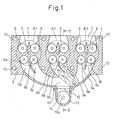
- FIG. 1 is a plan cross-sectional view of a cylinder head
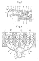
- FIG. 2 is a cross-sectional view of a cylinder head taken along the line II-II of FIG. 1
- FIG. 3 is a plan cross-sectional view showing another embodiment of a cylinder head
- FIG. 4 is a plan cross-sectional view showing still another embodiment of a cylinder head.
- 1 is a cylinder block, 2 a piston, 3 an integral exhaust manifold-type cylinder head, and 4 a combustion chamber.
- the broken lines respectively show the No. 1 cylinder #1, No. 2 cylinder #2, and No. 3 cylinder #3. Therefore, it is learned that the internal combustion engine shown in FIG. 1 and FIG. 2 has a plurality of cylinders arranged in a straight line.
- Each of the cylinders #1, #2, and #3 is provided with a spark plug 5, a pair of intake valves 6, an intake port 7, a pair of exhaust valves 8a, 8b, and a pair of exhaust ports 9a, 9b.
- the cylinder head 3 is formed with eight cylinder head bolt holes. Note that the cylinder head 3 actually has an extremely complicated shape, but in FIG. 1 and FIG. 2 , the cylinder head 3 is shown simplified.
- the exhaust ports 9a, 9b of the pair of cylinders positioned at the two ends, that is, the No. 1 cylinder #1 and No. 3 cylinder #3, and the exhaust ports 9a, 9b of the center cylinder positioned between the pair of cylinders #1, #3, that is, the No. 2 cylinder #2, are merged at the exhaust merging portion 11 formed in the cylinder head 3 and the exhaust outlet opening 12 of the exhaust merging portion 11 is formed on the side wall of the cylinder head 3 positioned at the outside of this exhaust merging portion 11.
- this exhaust outlet opening 12 is formed not at the center part of the cylinder head 3 in the longitudinal direction, but somewhat toward the No. 3 cylinder #3.
- this exhaust outlet opening 12 is connected to an exhaust flow passage 14 formed inside the exhaust pipe 13.
- a sensor 15 having a sensing part 15a liable to be damaged by deposition of moisture is arranged.
- this sensor 15 is comprised of an air-fuel ratio sensor.
- a sensor 15 is arranged on the top wall surface of the exhaust flow passage 14 in substantially the same plane as the top wall surface of the exhaust merging portion 11.
- the problem becomes the water droplets splashing from the inner wall surfaces of the exhaust ports 9a, 9b of the center cylinder #2. That is, if designating the opening part of the exhaust port 9a of the center cylinder #2 to the exhaust merging portion 11 as "Xa", the water droplets formed on inner wall surface of the exhaust port 9a splash along the direction of extension of the exhaust port 9a at the opening part Xa, that is, along the extended tubular shaped surface Ya of the opening part Xa of the exhaust port 9a to the exhaust merging portion 11.
- the exhaust ports 9a, 9b of the center cylinder #2 are formed so that the sensing part 15a of the sensor 15 is not included in the extended tubular shaped surfaces Ya, Yb of the opening parts Xa, Xb of the exhaust ports 9a, 9b of the center cylinder #2 to the exhaust merging portion 11.
- the exhaust ports 9a, 9b of the center cylinder #2 are formed so that the extended tubular shaped surfaces Ya, Yb of the opening parts Xa, Xb of the exhaust ports 9a, 9b of the center cylinder #2 to the exhaust merging portion 11 are not directed toward the exhaust outlet opening 12.
- the extended tubular shaped surfaces Ya, Yb of the opening parts Xa, Xb of the exhaust ports 9a, 9b of the center cylinder #2 to the exhaust merging portion 11 are directed to the inner wall surface of the exhaust merging portion 11 adjoining the exhaust outlet opening 12.
- the sensing part 15a of the sensor 15 is arranged at the exhaust inlet part of the exhaust flow passage 14 through which the exhaust gas exhausted from the cylinders #1, #2, and #3 successively flows.
- FIG. 3 shows another embodiment.
- the exhaust ports 9a, 9b of the center cylinder #2 are formed so as to be separated from each other toward the two sides of the exhaust outlet opening 12 the closer to the exhaust merging portion 11. Therefore, in this embodiment as well, to prevent the splashed water droplets from striking the sensing part 15a of the sensor 15, the exhaust ports 9a, 9b of the center cylinder #2 are formed so that the sensing part 15a of the sensor 15 is not contained in the extended tubular shaped surfaces Ya, Yb of the opening parts Xa, Xb of the exhaust ports 9a, 9b of the center cylinder #2 to the exhaust merging portion 11.
- the exhaust ports 9a, 9b of the center cylinder #2 are formed so that the extended tubular shaped surfaces Ya, Yb of the opening parts Xa, Xb of the exhaust ports 9a, 9b of the center cylinder #2 to the exhaust merging portion 11 are not directed toward the exhaust outlet opening 12.
- FIG. 4 shows the case of application of the present invention to an in-line 4-cylinder internal combustion engine having four cylinders #1, #2, #3, and #4.
- the exhaust ports 9a, 9b of the center cylinders #2, #3 are formed so that the sensing part 15a of the sensor 15 is not contained in the extended tubular shaped surfaces Ya, Yb of the opening parts Xa, Xb of the exhaust ports 9a, 9b of the pair of center cylinders #2, #3 to the exhaust merging portion 11.
- the exhaust ports 9a, 9b of the center cylinders #2, #3 are formed so that the extended tubular shaped surfaces Ya, Yb of the opening parts Xa, Xb of the exhaust ports 9a, 9b of the pair of center cylinders #2, #3 to the exhaust merging portion 11 are not directed toward the exhaust outlet opening 12.
Landscapes
- Engineering & Computer Science (AREA)
- Chemical & Material Sciences (AREA)
- Combustion & Propulsion (AREA)
- Mechanical Engineering (AREA)
- General Engineering & Computer Science (AREA)
- Exhaust Silencers (AREA)
- Cylinder Crankcases Of Internal Combustion Engines (AREA)
Abstract
Description
- The present invention relates to an exhaust device of an internal combustion engine.
- Known in the art is an internal combustion engine provided with a plurality of cylinders arranged on a straight line, for example, an in-line 4-cylinder internal combustion engine, in which a No. 1 cylinder and No. 4 cylinder skipping one ignition timing are connected to a first exhaust manifold, a No. 2 cylinder and No. 3 cylinder skipping one ignition timing are connected to a second exhaust manifold, an outlet of the first exhaust manifold and an outlet of the second exhaust manifold are connected to a common exhaust pipe, and an air-fuel ratio sensor is arranged in this common exhaust pipe (see Japanese Patent Publication (A) No.
2001-3798 - However, in an internal combustion engine provided with a plurality of cylinders arranged in a straight line, exhaust ports of a pair of cylinders positioned at two ends and an exhaust port of a center cylinder positioned between the pair of cylinders being merged at an exhaust merging portion formed in a cylinder head, and an exhaust outlet opening of the exhaust manifold being formed on a cylinder head side wall positioned outside of this exhaust merging portion, that is, in a so-called integral exhaust manifold-type cylinder head having the exhaust ports of the cylinders and the exhaust manifold of these exhaust ports formed in the cylinder head, the degree of freedom for arrangement of the exhaust ports of the cylinders is extremely low and the exhaust ports of the cylinders are formed so as to extend toward the exhaust outlet opening formed at the cylinder head side wall so that the exhaust gas from the cylinders is exhausted quickly from the exhaust outlet opening.
- In this regard, in such an internal combustion engine, when arranging a sensor at an exhaust inlet part of an exhaust pipe connected to the exhaust outlet opening, exhaust gas exhausted from each cylinder reaches the sensor immediately after exhaust, so it is possible to use the sensor to detect any changes in the exhaust gas ingredients with a good response. However, in this case, a problem arises if using as a sensor a sensor having a sensor part liable to be damaged by deposition of moisture. For example, when using as the sensor an air-fuel ratio sensor detecting the oxygen concentration in the exhaust gas, the sensing part of the sensor is formed from zirconia, so if moisture deposits on the sensing part and the sensing part is rapidly cooled, the problem arises that the thermal reaction will cause the sensing part to end up fracturing.
- That is, right after engine start when the engine temperature is low, the moisture contained in the exhaust gas exhausted from the combustion chambers sticks on the exhaust port inner wall surfaces and condenses. The condensed moisture merges to form large sized water droplets. These water droplets are splashed by the exhaust gas exhausted from the cylinders inside the exhaust manifold along the extended tubular shaped surfaces of the opening parts of exhaust ports to the exhaust manifold. In this regard, as explained above, in an internal combustion engine provided with an integral exhaust manifold-type cylinder head, the exhaust ports of the center cylinder are directed toward the exhaust outlet opening. As a result, the sensing part of the sensor is inevitably positioned in an extended tubular shaped surface of an opening part of an exhaust port to the exhaust manifold.
- Therefore, in this case, the problem arises that the large sized water droplets formed on the inner wall surfaces of the exhaust ports of the center cylinder are splashed by the exhaust gas and deposit on the sensing part of the sensor and as a result the sensing part of the sensor is damaged.
- An object of the present invention is to provide an exhaust device of internal combustion engine designed forming the exhaust ports of the center cylinder so that water droplets are not splashed on the sensing part of the sensor when using an integral exhaust manifold-type cylinder head.
- According to the present invention, there is provided an exhaust device of an internal combustion engine provided with a plurality of cylinders arranged in a straight line, exhaust ports of a pair of cylinders positioned at two ends and an exhaust port of a center cylinder positioned between the pair of cylinders being merged at an exhaust merging portion formed in a cylinder head, and an exhaust outlet opening of the exhaust merging portion being formed on a cylinder head side wall positioned outside of the exhaust merging portion, wherein a sensor having a sensing part liable to be damaged by deposition of moisture is arranged at an exhaust inlet part of an exhaust flow passage connected to said exhaust outlet opening, and the exhaust port of the center cylinder is formed so that the sensing part of the sensor is not contained in an extended tubular shaped surface of an opening part of the exhaust port of the center cylinder to the exhaust merging portion.
-
FIG. 1 is a plan cross-sectional view of a cylinder head,FIG. 2 is a cross-sectional view of a cylinder head taken along the line II-II ofFIG. 1 ,FIG. 3 is a plan cross-sectional view showing another embodiment of a cylinder head, andFIG. 4 is a plan cross-sectional view showing still another embodiment of a cylinder head. - Referring to
FIG. 1 andFIG. 2 , 1 is a cylinder block, 2 a piston, 3 an integral exhaust manifold-type cylinder head, and 4 a combustion chamber. InFIG. 1 , the broken lines respectively show the No. 1cylinder # 1, No. 2cylinder # 2, and No. 3cylinder # 3. Therefore, it is learned that the internal combustion engine shown inFIG. 1 andFIG. 2 has a plurality of cylinders arranged in a straight line. Each of thecylinders # 1, #2, and #3 is provided with aspark plug 5, a pair ofintake valves 6, anintake port 7, a pair ofexhaust valves exhaust ports FIG. 1 , thecylinder head 3 is formed with eight cylinder head bolt holes. Note that thecylinder head 3 actually has an extremely complicated shape, but inFIG. 1 andFIG. 2 , thecylinder head 3 is shown simplified. - As shown in
FIG. 1 , theexhaust ports cylinder # 1 and No. 3cylinder # 3, and theexhaust ports cylinders # 1, #3, that is, the No. 2cylinder # 2, are merged at theexhaust merging portion 11 formed in thecylinder head 3 and the exhaust outlet opening 12 of theexhaust merging portion 11 is formed on the side wall of thecylinder head 3 positioned at the outside of thisexhaust merging portion 11. In the embodiment shown inFIG. 1 , thisexhaust outlet opening 12 is formed not at the center part of thecylinder head 3 in the longitudinal direction, but somewhat toward the No. 3cylinder # 3. - In the embodiment shown in
FIG. 1 andFIG. 2 , thisexhaust outlet opening 12 is connected to anexhaust flow passage 14 formed inside theexhaust pipe 13. At the exhaust inlet part of thisexhaust flow passage 14, asensor 15 having asensing part 15a liable to be damaged by deposition of moisture is arranged. In the embodiment according to the present invention, thissensor 15 is comprised of an air-fuel ratio sensor. In the example shown inFIG. 2 , asensor 15 is arranged on the top wall surface of theexhaust flow passage 14 in substantially the same plane as the top wall surface of theexhaust merging portion 11. - In this regard, as explained above, right after engine start when the engine temperature is low, the moisture contained in the exhaust gas exhausted from the
combustion chamber 2 sticks to the inner wall surfaces of theexhaust ports cylinders # 1, #2, and #3 to the exhaust outlet opening 12. On the other hand, in the integral exhaust manifold-type cylinder head 3, the part forming the manifold is formed so as not to bulge outward as much as possible, so the exhaust gas exhausted from thecylinders # 1, #3 positioned at the two ends is changed in flow direction at theexhaust merging portion 11, then is exhausted from the exhaust outlet opening 12 to the inside of theexhaust pipe 13. In this case, the water droplets splashed from the inner wall surfaces of theexhaust ports cylinders # 1, #3 never strike thesensing part 15a of thesensor 15, so these water droplets do not particularly have to be paid much attention. - As opposed to this, the problem becomes the water droplets splashing from the inner wall surfaces of the
exhaust ports center cylinder # 2. That is, if designating the opening part of theexhaust port 9a of thecenter cylinder # 2 to theexhaust merging portion 11 as "Xa", the water droplets formed on inner wall surface of theexhaust port 9a splash along the direction of extension of theexhaust port 9a at the opening part Xa, that is, along the extended tubular shaped surface Ya of the opening part Xa of theexhaust port 9a to theexhaust merging portion 11. In the same way, if designating the opening part of theexhaust port 9b of thecenter cylinder # 2 to theexhaust merging portion 11 as "Xb", the water droplets formed on inner wall surface of theexhaust port 9b splash along the direction of extension of theexhaust port 9b at the opening part Xb, that is, along the extended tubular shaped surface Yb of the opening part Xb of theexhaust port 9b to theexhaust merging portion 11. - In this way, if water droplets splash from the inner wall surfaces of the
exhaust ports center cylinder # 2, depending on how theexhaust ports exhaust pipe 13 and strike thesensing part 15a of thesensor 15. Therefore, in the present invention, to prevent the splashed water droplets from striking thesensing part 15a of thesensor 15, theexhaust ports center cylinder # 2 are formed so that thesensing part 15a of thesensor 15 is not included in the extended tubular shaped surfaces Ya, Yb of the opening parts Xa, Xb of theexhaust ports center cylinder # 2 to theexhaust merging portion 11. - Note that, to further prevent the splashed water droplets from striking the
sensing part 15a of thesensor 15, it can be said to be preferable to prevent the splashed water droplets from being directed toward the exhaust outlet opening 12, that is, to prevent the extended tubular shaped surfaces Ya, Yb from being directed toward the exhaust outlet opening 12. Therefore, in the embodiment according to the present invention, as shown inFIG. 1 , theexhaust ports center cylinder # 2 are formed so that the extended tubular shaped surfaces Ya, Yb of the opening parts Xa, Xb of theexhaust ports center cylinder # 2 to theexhaust merging portion 11 are not directed toward the exhaust outlet opening 12. - In this case, in the embodiment shown in
FIG. 1 , the extended tubular shaped surfaces Ya, Yb of the opening parts Xa, Xb of theexhaust ports center cylinder # 2 to theexhaust merging portion 11 are directed to the inner wall surface of theexhaust merging portion 11 adjoining the exhaust outlet opening 12. Further, in the present invention, to enable even the exhaust gas exhausted from thecenter cylinder # 2 to flow through thesensing part 15a of thesensor 15, thesensing part 15a of thesensor 15 is arranged at the exhaust inlet part of theexhaust flow passage 14 through which the exhaust gas exhausted from thecylinders # 1, #2, and #3 successively flows. -
FIG. 3 shows another embodiment. In this embodiment, theexhaust ports center cylinder # 2 are formed so as to be separated from each other toward the two sides of the exhaust outlet opening 12 the closer to theexhaust merging portion 11. Therefore, in this embodiment as well, to prevent the splashed water droplets from striking thesensing part 15a of thesensor 15, theexhaust ports center cylinder # 2 are formed so that thesensing part 15a of thesensor 15 is not contained in the extended tubular shaped surfaces Ya, Yb of the opening parts Xa, Xb of theexhaust ports center cylinder # 2 to theexhaust merging portion 11. Further, in this embodiment as well, to prevent the splashed water droplets from further striking thesensing part 15a of thesensor 15, theexhaust ports center cylinder # 2 are formed so that the extended tubular shaped surfaces Ya, Yb of the opening parts Xa, Xb of theexhaust ports center cylinder # 2 to theexhaust merging portion 11 are not directed toward the exhaust outlet opening 12. -
FIG. 4 shows the case of application of the present invention to an in-line 4-cylinder internal combustion engine having fourcylinders # 1, #2, #3, and #4. As shown inFIG. 4 , in this case as well, to prevent the splashed water droplets from striking thesensing part 15a of thesensor 15, theexhaust ports center cylinders # 2, #3 are formed so that thesensing part 15a of thesensor 15 is not contained in the extended tubular shaped surfaces Ya, Yb of the opening parts Xa, Xb of theexhaust ports center cylinders # 2, #3 to theexhaust merging portion 11. Further, in this embodiment as well, to prevent the splashed water droplets from further striking thesensing part 15a of thesensor 15, theexhaust ports center cylinders # 2, #3 are formed so that the extended tubular shaped surfaces Ya, Yb of the opening parts Xa, Xb of theexhaust ports center cylinders # 2, #3 to theexhaust merging portion 11 are not directed toward the exhaust outlet opening 12.
Claims (4)
- An exhaust device of an internal combustion engine provided with a plurality of cylinders arranged in a straight line, exhaust ports of a pair of cylinders positioned at two ends and an exhaust port of a center cylinder positioned between the pair of cylinders being merged at an exhaust merging portion formed in a cylinder head, and an exhaust outlet opening of the exhaust merging portion being formed on a cylinder head side wall positioned outside of the exhaust merging portion, wherein a sensor having a sensing part liable to be damaged by deposition of moisture is arranged at an exhaust inlet part of an exhaust flow passage connected to said exhaust outlet opening, and the exhaust port of the center cylinder is formed so that the sensing part of the sensor is not contained in an extended tubular shaped surface of an opening part of the exhaust port of the center cylinder to the exhaust merging portion.
- An exhaust device of an internal combustion engine as claimed in claim 1, wherein said exhaust port of the center cylinder is formed so that the extended tubular shaped surface of the opening part of the exhaust port of the center cylinder to said exhaust merging portion is not directed toward said exhaust outlet opening.
- An exhaust device of an internal combustion engine as claimed in claim 2, wherein the extended tubular shaped surface of the opening part of the exhaust port of the center cylinder to said exhaust merging portion is directed toward an inner wall of said exhaust merging portion adjoining said exhaust outlet opening.
- An exhaust device of an internal combustion engine as claimed in claim 1, wherein the sensing part of said sensor is arranged at the exhaust inlet part of said exhaust flow passage through which exhaust gas exhausted from said cylinders sequentially flow.
Applications Claiming Priority (2)
| Application Number | Priority Date | Filing Date | Title |
|---|---|---|---|
| JP2007044192A JP4748081B2 (en) | 2007-02-23 | 2007-02-23 | Exhaust device for internal combustion engine |
| PCT/JP2008/053451 WO2008102917A1 (en) | 2007-02-23 | 2008-02-21 | Exhaust device for internal combustion engine |
Publications (3)
| Publication Number | Publication Date |
|---|---|
| EP2123892A1 true EP2123892A1 (en) | 2009-11-25 |
| EP2123892A4 EP2123892A4 (en) | 2014-01-08 |
| EP2123892B1 EP2123892B1 (en) | 2018-12-26 |
Family
ID=39710185
Family Applications (1)
| Application Number | Title | Priority Date | Filing Date |
|---|---|---|---|
| EP08712072.1A Not-in-force EP2123892B1 (en) | 2007-02-23 | 2008-02-21 | Exhaust device for internal combustion engine |
Country Status (8)
| Country | Link |
|---|---|
| US (1) | US8397494B2 (en) |
| EP (1) | EP2123892B1 (en) |
| JP (1) | JP4748081B2 (en) |
| KR (1) | KR101039540B1 (en) |
| CN (1) | CN101600875B (en) |
| CA (1) | CA2674911C (en) |
| ES (1) | ES2708143T3 (en) |
| WO (1) | WO2008102917A1 (en) |
Cited By (3)
| Publication number | Priority date | Publication date | Assignee | Title |
|---|---|---|---|---|
| EP2228529A1 (en) * | 2009-03-13 | 2010-09-15 | Ford Global Technologies, LLC | Cylinder head for a natural aspirated engine and usage of such a cylinder head |
| US20100269878A1 (en) * | 2009-04-23 | 2010-10-28 | Ford Global Technologies, Llc | Internal combustion engine with thermoelectric generator |
| EP2369161A3 (en) * | 2010-03-26 | 2015-05-20 | Bayerische Motoren Werke Aktiengesellschaft | Cylinder head and exhaust manifold and exhaust discharge assembly |
Families Citing this family (9)
| Publication number | Priority date | Publication date | Assignee | Title |
|---|---|---|---|---|
| EP2172635B1 (en) * | 2008-10-02 | 2018-12-12 | Ford Global Technologies, LLC | Cylinder head for an internal combustion engine with two integrated exhaust manifolds and method to operate an internal combustion engine with such a cylinder head |
| DE102009000214A1 (en) * | 2009-01-14 | 2010-09-02 | Ford Global Technologies, LLC, Dearborn | Internal combustion engine with turbocharging |
| JP5729984B2 (en) * | 2010-11-26 | 2015-06-03 | ダイハツ工業株式会社 | Exhaust structure of multi-cylinder engine |
| US8857385B2 (en) | 2011-06-13 | 2014-10-14 | Ford Global Technologies, Llc | Integrated exhaust cylinder head |
| JP5602121B2 (en) * | 2011-11-18 | 2014-10-08 | 本田技研工業株式会社 | Exhaust sensor mounting structure |
| KR20140065084A (en) | 2012-11-21 | 2014-05-29 | 현대자동차주식회사 | Cylinder head integrated exhaust manifold and diffuser |
| JP6221727B2 (en) * | 2013-12-18 | 2017-11-01 | 三菱自動車工業株式会社 | Cylinder head structure |
| JP6255989B2 (en) * | 2013-12-26 | 2018-01-10 | 三菱自動車工業株式会社 | Engine exhaust system |
| JP6222563B2 (en) * | 2013-12-26 | 2017-11-01 | 三菱自動車工業株式会社 | Engine exhaust system |
Family Cites Families (26)
| Publication number | Priority date | Publication date | Assignee | Title |
|---|---|---|---|---|
| JPS6114598Y2 (en) | 1979-12-28 | 1986-05-07 | ||
| JPS56101445A (en) * | 1980-01-19 | 1981-08-14 | Kamizaki Kokyu Koki Seisakusho Kk | Oil-hydraulic clutch device |
| JPS58106531U (en) | 1982-01-12 | 1983-07-20 | 日産自動車株式会社 | Air-fuel ratio control device for multi-cylinder internal combustion engine |
| JPS5952119U (en) | 1982-09-30 | 1984-04-05 | トヨタ自動車株式会社 | Exhaust purification device |
| JPH055215Y2 (en) * | 1986-10-28 | 1993-02-10 | ||
| JP3046435B2 (en) * | 1991-09-11 | 2000-05-29 | ヤマハ発動機株式会社 | Motorcycle oxygen sensor protection device |
| JP3378474B2 (en) * | 1997-08-06 | 2003-02-17 | トヨタ自動車株式会社 | Exhaust manifold of internal combustion engine |
| JPH1181999A (en) * | 1997-09-12 | 1999-03-26 | Honda Motor Co Ltd | Exhaust gas purification device for internal combustion engine |
| FR2777320B1 (en) * | 1998-04-09 | 2000-09-22 | Renault | EXHAUST MANIFOLD FOR INTERNAL COMBUSTION ENGINE |
| JP2000130225A (en) * | 1998-10-21 | 2000-05-09 | Sanshin Ind Co Ltd | Engine and outboard engine provided with engine |
| US6230490B1 (en) * | 1998-11-09 | 2001-05-15 | Suzuki Motor Corp. | Exhaust manifold for internal combustion engines |
| EP1722090B1 (en) * | 1998-12-01 | 2013-07-17 | Honda Giken Kogyo Kabushiki Kaisha | Cylinder head structure in multi-cylinder engine |
| JP2000205043A (en) * | 1999-01-13 | 2000-07-25 | Honda Motor Co Ltd | Multi-cylinder engine |
| JP4252662B2 (en) | 1999-03-10 | 2009-04-08 | 本田技研工業株式会社 | Multi-cylinder engine |
| JP2000265905A (en) | 1999-03-18 | 2000-09-26 | Honda Motor Co Ltd | Multi-cylinder engine |
| JP3882401B2 (en) | 1999-06-16 | 2007-02-14 | トヨタ自動車株式会社 | Exhaust gas purification device for internal combustion engine |
| JP2002070609A (en) | 2000-08-25 | 2002-03-08 | Honda Motor Co Ltd | Multi-cylinder engine |
| JP2002303145A (en) * | 2001-04-05 | 2002-10-18 | Toyota Motor Corp | Internal combustion engine with turbocharger |
| KR20030027401A (en) * | 2001-09-28 | 2003-04-07 | 현대자동차주식회사 | Exhaust manifold structure of vehicle |
| JP3791419B2 (en) * | 2002-01-17 | 2006-06-28 | 日産自動車株式会社 | Exhaust device for internal combustion engine |
| JP2003262120A (en) * | 2002-03-08 | 2003-09-19 | Nissan Motor Co Ltd | Exhaust manifold for 4-cylinder engine |
| JP4231303B2 (en) * | 2003-02-24 | 2009-02-25 | トヨタ自動車株式会社 | Exhaust pipe and exhaust gas purification device for internal combustion engine |
| DE20303759U1 (en) * | 2003-03-10 | 2004-07-22 | Friedrich Boysen Gmbh & Co. Kg | Exhaust system of an internal combustion engine |
| DE602004006698T2 (en) * | 2003-12-01 | 2007-10-04 | Nissan Motor Co., Ltd., Yokohama | Exhaust manifold for an internal combustion engine |
| JP2007114004A (en) * | 2005-10-19 | 2007-05-10 | Hitachi Ltd | Oxygen sensor |
| US7552586B1 (en) * | 2005-12-12 | 2009-06-30 | Brunswick Corporation | Marine exhaust system with a downstream oxygen sensor located away from a water reversion liquid trajectory path |
-
2007
- 2007-02-23 JP JP2007044192A patent/JP4748081B2/en not_active Expired - Fee Related
-
2008
- 2008-02-21 ES ES08712072T patent/ES2708143T3/en active Active
- 2008-02-21 CN CN2008800027172A patent/CN101600875B/en not_active Expired - Fee Related
- 2008-02-21 EP EP08712072.1A patent/EP2123892B1/en not_active Not-in-force
- 2008-02-21 KR KR1020097012628A patent/KR101039540B1/en not_active Expired - Fee Related
- 2008-02-21 US US12/448,682 patent/US8397494B2/en not_active Expired - Fee Related
- 2008-02-21 WO PCT/JP2008/053451 patent/WO2008102917A1/en not_active Ceased
- 2008-02-21 CA CA2674911A patent/CA2674911C/en not_active Expired - Fee Related
Cited By (6)
| Publication number | Priority date | Publication date | Assignee | Title |
|---|---|---|---|---|
| EP2228529A1 (en) * | 2009-03-13 | 2010-09-15 | Ford Global Technologies, LLC | Cylinder head for a natural aspirated engine and usage of such a cylinder head |
| US20100229819A1 (en) * | 2009-03-13 | 2010-09-16 | Ford Global Technologies, Llc | Cylinder head for an internal combustion engine |
| US8256213B2 (en) * | 2009-03-13 | 2012-09-04 | Ford Global Technologies, Llc | Cylinder head for an internal combustion engine |
| EP2228529B1 (en) | 2009-03-13 | 2016-07-27 | Ford Global Technologies, LLC | Cylinder head for a natural aspirated engine and usage of such a cylinder head |
| US20100269878A1 (en) * | 2009-04-23 | 2010-10-28 | Ford Global Technologies, Llc | Internal combustion engine with thermoelectric generator |
| EP2369161A3 (en) * | 2010-03-26 | 2015-05-20 | Bayerische Motoren Werke Aktiengesellschaft | Cylinder head and exhaust manifold and exhaust discharge assembly |
Also Published As
| Publication number | Publication date |
|---|---|
| KR101039540B1 (en) | 2011-06-09 |
| CA2674911A1 (en) | 2008-08-28 |
| CA2674911C (en) | 2011-08-30 |
| WO2008102917A1 (en) | 2008-08-28 |
| US20100011756A1 (en) | 2010-01-21 |
| CN101600875B (en) | 2012-01-25 |
| EP2123892A4 (en) | 2014-01-08 |
| EP2123892B1 (en) | 2018-12-26 |
| ES2708143T3 (en) | 2019-04-08 |
| US8397494B2 (en) | 2013-03-19 |
| JP2008208738A (en) | 2008-09-11 |
| KR20090092810A (en) | 2009-09-01 |
| CN101600875A (en) | 2009-12-09 |
| JP4748081B2 (en) | 2011-08-17 |
Similar Documents
| Publication | Publication Date | Title |
|---|---|---|
| US8397494B2 (en) | Exhaust device of internal combustion engine | |
| US20100126153A1 (en) | Internal combustion engine | |
| US8714128B2 (en) | Cylinder head for an internal combustion engine, with integrated exhaust manifold and subgroups of exhaust conduits merging into manifold portions which are superimposed and spaced apart from each other | |
| US7849683B2 (en) | Multiple-cylinder internal combustion engine having cylinder head provided with centralized exhaust passageway | |
| US20090025664A1 (en) | Internal combustion engine | |
| US20120031355A1 (en) | Engine including partial integrated intake manifold | |
| CN108443026B (en) | cylinder head | |
| JP2011094523A (en) | Cooling water passage structure in cylinder head of internal combustion engine | |
| JP4998339B2 (en) | Cooling device for internal combustion engine | |
| JP6079405B2 (en) | Exhaust gas recirculation device for vehicle engine | |
| US7757654B2 (en) | Cylinder head | |
| JP2005105983A5 (en) | ||
| EP1069300A3 (en) | Internal combustion engine with cylinder head having bolt and port arrangement | |
| JP2009162205A (en) | Exhaust gas reflux device in internal combustion engine | |
| JP5943978B2 (en) | Breather equipment | |
| JP2009281247A (en) | Blowby gas treatment system for multiple cylinder engine | |
| JP2010223173A (en) | Exhaust gas recirculation device | |
| JP2008057360A (en) | Engine exhaust gas recirculation system | |
| JP6258654B2 (en) | Internal combustion engine | |
| JP2007231896A (en) | In-cylinder fuel injection engine | |
| JP5381426B2 (en) | Internal combustion engine exhaust pipe | |
| JP5824946B2 (en) | Multi-cylinder engine | |
| US20160222922A1 (en) | Exhaust emission control device for internal combustion engine | |
| US20070028598A1 (en) | Single cylinder engine with ternary catalyst in exhaust passage and vehicle provided with same | |
| JP2008150969A (en) | Internal combustion engine |
Legal Events
| Date | Code | Title | Description |
|---|---|---|---|
| PUAI | Public reference made under article 153(3) epc to a published international application that has entered the european phase |
Free format text: ORIGINAL CODE: 0009012 |
|
| 17P | Request for examination filed |
Effective date: 20090709 |
|
| AK | Designated contracting states |
Kind code of ref document: A1 Designated state(s): AT BE BG CH CY CZ DE DK EE ES FI FR GB GR HR HU IE IS IT LI LT LU LV MC MT NL NO PL PT RO SE SI SK TR |
|
| DAX | Request for extension of the european patent (deleted) | ||
| RAP1 | Party data changed (applicant data changed or rights of an application transferred) |
Owner name: TOYOTA JIDOSHA KABUSHIKI KAISHA |
|
| A4 | Supplementary search report drawn up and despatched |
Effective date: 20131206 |
|
| RIC1 | Information provided on ipc code assigned before grant |
Ipc: F02F 1/42 20060101AFI20131202BHEP Ipc: F02D 35/00 20060101ALI20131202BHEP |
|
| STAA | Information on the status of an ep patent application or granted ep patent |
Free format text: STATUS: EXAMINATION IS IN PROGRESS |
|
| 17Q | First examination report despatched |
Effective date: 20170320 |
|
| GRAP | Despatch of communication of intention to grant a patent |
Free format text: ORIGINAL CODE: EPIDOSNIGR1 |
|
| STAA | Information on the status of an ep patent application or granted ep patent |
Free format text: STATUS: GRANT OF PATENT IS INTENDED |
|
| INTG | Intention to grant announced |
Effective date: 20180717 |
|
| GRAS | Grant fee paid |
Free format text: ORIGINAL CODE: EPIDOSNIGR3 |
|
| GRAA | (expected) grant |
Free format text: ORIGINAL CODE: 0009210 |
|
| STAA | Information on the status of an ep patent application or granted ep patent |
Free format text: STATUS: THE PATENT HAS BEEN GRANTED |
|
| AK | Designated contracting states |
Kind code of ref document: B1 Designated state(s): AT BE BG CH CY CZ DE DK EE ES FI FR GB GR HR HU IE IS IT LI LT LU LV MC MT NL NO PL PT RO SE SI SK TR |
|
| REG | Reference to a national code |
Ref country code: GB Ref legal event code: FG4D |
|
| REG | Reference to a national code |
Ref country code: CH Ref legal event code: EP |
|
| REG | Reference to a national code |
Ref country code: AT Ref legal event code: REF Ref document number: 1081759 Country of ref document: AT Kind code of ref document: T Effective date: 20190115 |
|
| REG | Reference to a national code |
Ref country code: DE Ref legal event code: R096 Ref document number: 602008058453 Country of ref document: DE |
|
| REG | Reference to a national code |
Ref country code: IE Ref legal event code: FG4D |
|
| REG | Reference to a national code |
Ref country code: DE Ref legal event code: R084 Ref document number: 602008058453 Country of ref document: DE |
|
| REG | Reference to a national code |
Ref country code: ES Ref legal event code: FG2A Ref document number: 2708143 Country of ref document: ES Kind code of ref document: T3 Effective date: 20190408 |
|
| REG | Reference to a national code |
Ref country code: GB Ref legal event code: 746 Effective date: 20190401 |
|
| PG25 | Lapsed in a contracting state [announced via postgrant information from national office to epo] |
Ref country code: LV Free format text: LAPSE BECAUSE OF FAILURE TO SUBMIT A TRANSLATION OF THE DESCRIPTION OR TO PAY THE FEE WITHIN THE PRESCRIBED TIME-LIMIT Effective date: 20181226 Ref country code: HR Free format text: LAPSE BECAUSE OF FAILURE TO SUBMIT A TRANSLATION OF THE DESCRIPTION OR TO PAY THE FEE WITHIN THE PRESCRIBED TIME-LIMIT Effective date: 20181226 Ref country code: FI Free format text: LAPSE BECAUSE OF FAILURE TO SUBMIT A TRANSLATION OF THE DESCRIPTION OR TO PAY THE FEE WITHIN THE PRESCRIBED TIME-LIMIT Effective date: 20181226 Ref country code: NO Free format text: LAPSE BECAUSE OF FAILURE TO SUBMIT A TRANSLATION OF THE DESCRIPTION OR TO PAY THE FEE WITHIN THE PRESCRIBED TIME-LIMIT Effective date: 20190326 Ref country code: LT Free format text: LAPSE BECAUSE OF FAILURE TO SUBMIT A TRANSLATION OF THE DESCRIPTION OR TO PAY THE FEE WITHIN THE PRESCRIBED TIME-LIMIT Effective date: 20181226 Ref country code: BG Free format text: LAPSE BECAUSE OF FAILURE TO SUBMIT A TRANSLATION OF THE DESCRIPTION OR TO PAY THE FEE WITHIN THE PRESCRIBED TIME-LIMIT Effective date: 20190326 |
|
| REG | Reference to a national code |
Ref country code: NL Ref legal event code: MP Effective date: 20181226 |
|
| REG | Reference to a national code |
Ref country code: LT Ref legal event code: MG4D |
|
| PG25 | Lapsed in a contracting state [announced via postgrant information from national office to epo] |
Ref country code: GR Free format text: LAPSE BECAUSE OF FAILURE TO SUBMIT A TRANSLATION OF THE DESCRIPTION OR TO PAY THE FEE WITHIN THE PRESCRIBED TIME-LIMIT Effective date: 20190327 Ref country code: SE Free format text: LAPSE BECAUSE OF FAILURE TO SUBMIT A TRANSLATION OF THE DESCRIPTION OR TO PAY THE FEE WITHIN THE PRESCRIBED TIME-LIMIT Effective date: 20181226 |
|
| REG | Reference to a national code |
Ref country code: AT Ref legal event code: MK05 Ref document number: 1081759 Country of ref document: AT Kind code of ref document: T Effective date: 20181226 |
|
| PG25 | Lapsed in a contracting state [announced via postgrant information from national office to epo] |
Ref country code: NL Free format text: LAPSE BECAUSE OF FAILURE TO SUBMIT A TRANSLATION OF THE DESCRIPTION OR TO PAY THE FEE WITHIN THE PRESCRIBED TIME-LIMIT Effective date: 20181226 |
|
| PG25 | Lapsed in a contracting state [announced via postgrant information from national office to epo] |
Ref country code: PL Free format text: LAPSE BECAUSE OF FAILURE TO SUBMIT A TRANSLATION OF THE DESCRIPTION OR TO PAY THE FEE WITHIN THE PRESCRIBED TIME-LIMIT Effective date: 20181226 Ref country code: PT Free format text: LAPSE BECAUSE OF FAILURE TO SUBMIT A TRANSLATION OF THE DESCRIPTION OR TO PAY THE FEE WITHIN THE PRESCRIBED TIME-LIMIT Effective date: 20190426 |
|
| PG25 | Lapsed in a contracting state [announced via postgrant information from national office to epo] |
Ref country code: RO Free format text: LAPSE BECAUSE OF FAILURE TO SUBMIT A TRANSLATION OF THE DESCRIPTION OR TO PAY THE FEE WITHIN THE PRESCRIBED TIME-LIMIT Effective date: 20181226 Ref country code: SK Free format text: LAPSE BECAUSE OF FAILURE TO SUBMIT A TRANSLATION OF THE DESCRIPTION OR TO PAY THE FEE WITHIN THE PRESCRIBED TIME-LIMIT Effective date: 20181226 Ref country code: EE Free format text: LAPSE BECAUSE OF FAILURE TO SUBMIT A TRANSLATION OF THE DESCRIPTION OR TO PAY THE FEE WITHIN THE PRESCRIBED TIME-LIMIT Effective date: 20181226 Ref country code: IS Free format text: LAPSE BECAUSE OF FAILURE TO SUBMIT A TRANSLATION OF THE DESCRIPTION OR TO PAY THE FEE WITHIN THE PRESCRIBED TIME-LIMIT Effective date: 20190426 |
|
| REG | Reference to a national code |
Ref country code: DE Ref legal event code: R097 Ref document number: 602008058453 Country of ref document: DE |
|
| REG | Reference to a national code |
Ref country code: CH Ref legal event code: PL |
|
| PG25 | Lapsed in a contracting state [announced via postgrant information from national office to epo] |
Ref country code: MC Free format text: LAPSE BECAUSE OF FAILURE TO SUBMIT A TRANSLATION OF THE DESCRIPTION OR TO PAY THE FEE WITHIN THE PRESCRIBED TIME-LIMIT Effective date: 20181226 Ref country code: DK Free format text: LAPSE BECAUSE OF FAILURE TO SUBMIT A TRANSLATION OF THE DESCRIPTION OR TO PAY THE FEE WITHIN THE PRESCRIBED TIME-LIMIT Effective date: 20181226 Ref country code: LU Free format text: LAPSE BECAUSE OF NON-PAYMENT OF DUE FEES Effective date: 20190221 Ref country code: AT Free format text: LAPSE BECAUSE OF FAILURE TO SUBMIT A TRANSLATION OF THE DESCRIPTION OR TO PAY THE FEE WITHIN THE PRESCRIBED TIME-LIMIT Effective date: 20181226 |
|
| PLBE | No opposition filed within time limit |
Free format text: ORIGINAL CODE: 0009261 |
|
| STAA | Information on the status of an ep patent application or granted ep patent |
Free format text: STATUS: NO OPPOSITION FILED WITHIN TIME LIMIT |
|
| REG | Reference to a national code |
Ref country code: BE Ref legal event code: MM Effective date: 20190228 |
|
| REG | Reference to a national code |
Ref country code: IE Ref legal event code: MM4A |
|
| 26N | No opposition filed |
Effective date: 20190927 |
|
| PG25 | Lapsed in a contracting state [announced via postgrant information from national office to epo] |
Ref country code: CH Free format text: LAPSE BECAUSE OF NON-PAYMENT OF DUE FEES Effective date: 20190228 Ref country code: LI Free format text: LAPSE BECAUSE OF NON-PAYMENT OF DUE FEES Effective date: 20190228 |
|
| PG25 | Lapsed in a contracting state [announced via postgrant information from national office to epo] |
Ref country code: IE Free format text: LAPSE BECAUSE OF NON-PAYMENT OF DUE FEES Effective date: 20190221 |
|
| PG25 | Lapsed in a contracting state [announced via postgrant information from national office to epo] |
Ref country code: BE Free format text: LAPSE BECAUSE OF NON-PAYMENT OF DUE FEES Effective date: 20190228 Ref country code: SI Free format text: LAPSE BECAUSE OF FAILURE TO SUBMIT A TRANSLATION OF THE DESCRIPTION OR TO PAY THE FEE WITHIN THE PRESCRIBED TIME-LIMIT Effective date: 20181226 |
|
| PG25 | Lapsed in a contracting state [announced via postgrant information from national office to epo] |
Ref country code: TR Free format text: LAPSE BECAUSE OF FAILURE TO SUBMIT A TRANSLATION OF THE DESCRIPTION OR TO PAY THE FEE WITHIN THE PRESCRIBED TIME-LIMIT Effective date: 20181226 |
|
| PGFP | Annual fee paid to national office [announced via postgrant information from national office to epo] |
Ref country code: IT Payment date: 20200128 Year of fee payment: 13 Ref country code: DE Payment date: 20200211 Year of fee payment: 13 Ref country code: GB Payment date: 20200212 Year of fee payment: 13 Ref country code: ES Payment date: 20200302 Year of fee payment: 13 |
|
| PGFP | Annual fee paid to national office [announced via postgrant information from national office to epo] |
Ref country code: CZ Payment date: 20200129 Year of fee payment: 13 |
|
| PG25 | Lapsed in a contracting state [announced via postgrant information from national office to epo] |
Ref country code: MT Free format text: LAPSE BECAUSE OF NON-PAYMENT OF DUE FEES Effective date: 20190221 |
|
| PGFP | Annual fee paid to national office [announced via postgrant information from national office to epo] |
Ref country code: FR Payment date: 20200113 Year of fee payment: 13 |
|
| PG25 | Lapsed in a contracting state [announced via postgrant information from national office to epo] |
Ref country code: CY Free format text: LAPSE BECAUSE OF FAILURE TO SUBMIT A TRANSLATION OF THE DESCRIPTION OR TO PAY THE FEE WITHIN THE PRESCRIBED TIME-LIMIT Effective date: 20181226 |
|
| PG25 | Lapsed in a contracting state [announced via postgrant information from national office to epo] |
Ref country code: HU Free format text: LAPSE BECAUSE OF FAILURE TO SUBMIT A TRANSLATION OF THE DESCRIPTION OR TO PAY THE FEE WITHIN THE PRESCRIBED TIME-LIMIT; INVALID AB INITIO Effective date: 20080221 |
|
| REG | Reference to a national code |
Ref country code: DE Ref legal event code: R119 Ref document number: 602008058453 Country of ref document: DE |
|
| GBPC | Gb: european patent ceased through non-payment of renewal fee |
Effective date: 20210221 |
|
| PG25 | Lapsed in a contracting state [announced via postgrant information from national office to epo] |
Ref country code: CZ Free format text: LAPSE BECAUSE OF NON-PAYMENT OF DUE FEES Effective date: 20210221 |
|
| PG25 | Lapsed in a contracting state [announced via postgrant information from national office to epo] |
Ref country code: DE Free format text: LAPSE BECAUSE OF NON-PAYMENT OF DUE FEES Effective date: 20210901 Ref country code: GB Free format text: LAPSE BECAUSE OF NON-PAYMENT OF DUE FEES Effective date: 20210221 Ref country code: FR Free format text: LAPSE BECAUSE OF NON-PAYMENT OF DUE FEES Effective date: 20210228 |
|
| PG25 | Lapsed in a contracting state [announced via postgrant information from national office to epo] |
Ref country code: IT Free format text: LAPSE BECAUSE OF NON-PAYMENT OF DUE FEES Effective date: 20210221 |
|
| REG | Reference to a national code |
Ref country code: ES Ref legal event code: FD2A Effective date: 20220513 |
|
| PG25 | Lapsed in a contracting state [announced via postgrant information from national office to epo] |
Ref country code: ES Free format text: LAPSE BECAUSE OF NON-PAYMENT OF DUE FEES Effective date: 20210222 |