EP2123322B1 - Valve connector for medical lines - Google Patents
Valve connector for medical lines Download PDFInfo
- Publication number
- EP2123322B1 EP2123322B1 EP09160641.8A EP09160641A EP2123322B1 EP 2123322 B1 EP2123322 B1 EP 2123322B1 EP 09160641 A EP09160641 A EP 09160641A EP 2123322 B1 EP2123322 B1 EP 2123322B1
- Authority
- EP
- European Patent Office
- Prior art keywords
- elastic
- tubular body
- valve connector
- connector according
- head
- Prior art date
- Legal status (The legal status is an assumption and is not a legal conclusion. Google has not performed a legal analysis and makes no representation as to the accuracy of the status listed.)
- Active
Links
Images





Classifications
-
- A—HUMAN NECESSITIES
- A61—MEDICAL OR VETERINARY SCIENCE; HYGIENE
- A61M—DEVICES FOR INTRODUCING MEDIA INTO, OR ONTO, THE BODY; DEVICES FOR TRANSDUCING BODY MEDIA OR FOR TAKING MEDIA FROM THE BODY; DEVICES FOR PRODUCING OR ENDING SLEEP OR STUPOR
- A61M39/00—Tubes, tube connectors, tube couplings, valves, access sites or the like, specially adapted for medical use
- A61M39/22—Valves or arrangement of valves
- A61M39/26—Valves closing automatically on disconnecting the line and opening on reconnection thereof
-
- A—HUMAN NECESSITIES
- A61—MEDICAL OR VETERINARY SCIENCE; HYGIENE
- A61M—DEVICES FOR INTRODUCING MEDIA INTO, OR ONTO, THE BODY; DEVICES FOR TRANSDUCING BODY MEDIA OR FOR TAKING MEDIA FROM THE BODY; DEVICES FOR PRODUCING OR ENDING SLEEP OR STUPOR
- A61M39/00—Tubes, tube connectors, tube couplings, valves, access sites or the like, specially adapted for medical use
- A61M39/02—Access sites
- A61M39/04—Access sites having pierceable self-sealing members
- A61M39/045—Access sites having pierceable self-sealing members pre-slit to be pierced by blunt instrument
Definitions
- the present invention refers to valve connectors for medical lines, for example for infusion, by means of an introducer of a fluid infusion substance, typically a Luer connector or Luer-Lock for example of a needleless syringe.
- a fluid infusion substance typically a Luer connector or Luer-Lock for example of a needleless syringe.
- valve connector according to the preamble of claim 1, wherein provided is a tubular body having a cavity, an inlet end designed for the engagement of a liquid introducer, and an outlet end.
- a hollow spike is arranged axially into the cavity of the tubular body and it has a closed tip facing the inlet end of the tubular body and axially spaced by the latter.
- the hollow spike is in communication with the outlet end of the tubular body and it has a lateral hole spaced from its closed tip for communication with the cavity of the tubular body.
- the connector further includes a sealing elastic member which comprises an elastic head having a pre-slit and normally arranged in a closure condition (or deactivated condition) into the inlet end of the tubular body, in which the pre-slit is closed.
- the elastic head is axially moveable against the closed tip of the hollow spike upon insertion of the introducer into the inlet end of the tubular body, to interact with such tip taking an elastically deformed condition of opening (or activated condition), in which the pre-slit opens.
- the sealing member of the valve connector further includes an elastic hollow element joined to the head, interposed between the tubular body and the hollow spike and having sealing means in contact with such hollow spike to isolate the above mentioned lateral hole with respect to the cavity of the tubular body when the head is arranged in the undeformed closure condition.
- the elastic hollow element includes an elastic thrust means tending to maintain the head of the sealing member in the abovementioned closure condition.
- Such elastic thrust means includes a base part having a generally cylindrical axial wall radially spaced from the hollow spike to define an annular chamber therewith.
- the base part is joined to the elastic hollow element through a generally transverse annular wall which, during the axial movement of the elastic head from the closure condition to the opening condition, bends inside the annular chamber.
- this known connector is capable of satisfactorily bearing any slight overpressures that might occur therein during its use, and it guarantees an efficient resistance against positive and negative pressures in the closure or deactivated condition.
- a medical flow valve including a resilient hollow sealing member having a seal cap with a slit, and an annular tapered member cooperating with a tapered wall of the valve housing to squeeze a portion of the seal wall.
- the annular tapered member Upon activation of the valve, the annular tapered member enables radial expansion of the portion of seal surrounded thereby.
- WO-96/13301 discloses a medical valved connector whose resilient hollow valve member has a head portion with a slit and a surronding ring. The ring merely restricts radial expansion of the head portion and provides compression thereof upon activation of the connector.
- the present invention is an improvement of the valve connector known from the previously mentioned document EP-1834665A1 , and in particular it has the object of increasing the airtight sealing of the connector in its activated condition, or in the elastically deformed condition of the elastic hollow element of the sealing member, even up to internal overpressures far exceeding values in the order of 100 psi.
- valve connector according to the invention is provided with an improved degree of reliability, guaranteeing the airtight sealing in its activated condition even in case of generation of overpressures therein reaching up to values in the order of 300 psi and above in its activated condition.
- valve connector for infusion medical lines is generally similar to that described and illustrated in abovementioned document EP-1834665A1 and essentially includes four components: an external tubular body 1, an internal hollow spike 2 arranged axially into the cavity of the tubular body 1, a sealing elastic member 3, and a further document described hereinafter.
- the tubular body 1 and the hollow spike 2 are made of moulded rigid plastic material, while the sealing member 3 is made of elastic material, for example silicone rubber.
- the tubular body 1 has an inlet end 4 shaped like a female Luer-Lock connection member for the engagement, in a generally conventional manner, with a male Luer or Luer-Lock connection member of a fluid introducer, for example represented by a needleless syringe.
- the inlet end 4 is fitted to a generally cylindrical intermediate portion 5 followed by a widened end portion 6, also generally cylindrical.
- the internal surface of the inlet end 4 has a cylindrical initial part made with axial channels 7, and the internal surface of the intermediate part 5 has, in succession towards the final portion 6, cylindrical and frusto-conical portions.
- An intermediate cylindrical portion is indicated with 8 and it defines a sliding guide surface described hereinafter.
- the hollow spike 2 has a base generally indicated with 9, made externally with a gripping ring and shaped internally like a male Luer-Locker connection member with a central tubular shank 10 with a slightly conical external surface defining the outlet end of the valve connector 1. Such end could also be shake like a connector of any other type.
- the base 9 is made with a first annular flange 25 of a larger diameter, for joining the edge of the free end of the widened end portion 6 of the tubular body 1, and an annular flange of a smaller diameter 26.
- Branching off integrally from such annular flange 26 is a tubular post 28 including an initial portion having a conical surface 29, divergent towards the outlet end 10 of the connector, followed by a cylindrical portion 30 made with a single lateral through hole 31.
- the cylindrical portion 30 has - at its free end - a closed tip 32 facing the inlet end 4 of the tubular body 1 and located at a given axial distance from the latter.
- a ring of radial/axial projections 33 Projecting from the closed tip 32 is a ring of radial/axial projections 33 angularly spaced in such a manner to define radial/axial flow channels therebetween, in manner corresponding to that described and illustrated in the previously mentioned document EP-1834665A1 .
- the closed tip 32 is fitted to the cylindrical portion 30 through a conical surface.
- the sealing member 3 comprises, in a single piece, an elastic head 35, an elastic hollow element 36 and an elastic base 37.
- the general shape of the sealing member 3, and in particular its external configuration, substantially corresponds to that of the cavity of the tubular body 1, inside which it is accommodated.
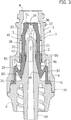
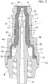
- the elastic head 35 has a cylindrical external surface complementary to that of the internal surface of the inlet end 4 in such a manner to be accommodated therein, as represented in figures 2 and 3 , with slight radial clearance or without substantial interference, in a closure condition in which such head 35 is substantially undeformed and substantially flushed with respect to the inlet end 4.
- the elastic head 35 conveniently has the configuration represented more in detail in figure 9 , with an end well 35a having an external surface slightly concave and an internal annular recess 35b shaped in the illustrated manner and connected to the internal wall of the sealing member 3 through a generally cylindrical part 35c followed by a first portion having a conical surface 35d with lower conicity and by a second portion having a conical surface 35e with greater conicity.
- a pre-slit or axial notch 38 Formed through the wall 35a of the head 35 is a pre-slit or axial notch 38 which, in the undeformed closure condition of the elastic head 35 into the inlet end 4, is maintained gripped due to the elasticity of the head 35.
- an anti-bacterial protection barrier is formed between the inside of the valve connector and the outside, ensuring at the same time the possibility of an effective cleaning conventionally performed by means of a swab soaked in a disinfectant.
- the external lateral surface of the elastic hollow element 36 has a general configuration complementary, with clearance, to that of the internal surface of the tubular body 1, having cylindrical and frusto-conical portions.
- An intermediate cylindrical portion is indicated with 42.
- the elastic base 37 is fitted to the elastic hollow element 36 through a generally transverse wall 45 which, in the undeformed condition of the sealing member 3, has a frusto-conical configuration.
- the elastic base 37 ends, on the part opposite to the elastic head 35, with an external annular flange 46 through which such elastic base 37 is gripped and blocked axially against the annular shoulder 26 of the base 9 of the hollow spike 2.
- the sealing member 3 is formed with a first annular projection 47 and with a second annular projection 48 axially spaced from each other and adapted to respectively define, through the method outlined hereinafter, a first and a second sealing member.
- the first internal sealing member 47 of the sealing member 3 is arranged in sealing contact against the surface of the tip 32 of the hollow spike 2, while the second sealing member 48 is arranged in sealing contact against the zone of the cylindrical part 30 adjacent to the conical part 29.
- Such zone illustrated more in detail in figure 8 and indicated with 30a, has an external diameter slightly greater than that of the cylindrical part 30 and it is formed with an external annular projection 56 adapted to cooperate, in the manner outlined hereinafter, with the sealing member 47.
- the lateral hole 31 of the hollow spike 2 is usually hermetically isolated by the sealing members 47 and 48 with respect to the inlet end 4 of the connector, whose communication with the outlet end 10 is thus closed.
- annular chamber 50 defined between the base 37 of the elastic sealing member 3 and the frusto-conical part 29 of the hollow spike 2 is an annular chamber 50 which communicates with the external of the valve connector through one or more passages made in the base 9 of the hollow spike 2, and whose internal pressure is thus the atmospheric pressure.
- Indicated with 55 is a substantially inextensible ring, for example made of rigid plastic material, which represents the fourth component of the connector and externally surrounds the elastic hollow element 36 of the sealing member 3.
- the ring 55 is engaged onto the cylindrical portion 42 of the elastic hollow element 36, at an axial position substantially corresponding to the sealing member 47, and it is guided with clearance in an axially sliding manner along the internal cylindrical portion 8 of the tubular body 1.
- the ring 55 may be provided internally, in the median zone thereof, with an annular projection not visible in the drawing, having the function of improving its gripping on the elastic hollow element 36.
- figure 1 represents the watertight closure condition of the valve connector.
- the wall 45 continues to undergo deflection inside the annular chamber 50, deforming progressively.
- the elastic head 35 and the elastic hollow element 36 of the sealing member 3 then slide progressively into the tubular body 1 and along the tubular post 28 of the hollow spike 2, in such a manner that the first sealing member 47 moves away from the conical surface 32a of the tip 32, while the second sealing member 48 slides along the conical part 29.
- the projections of the tip 32 of the hollow spike 2 start to interact from inside with the elastic head 35 which, due to its distinctive configuration and in particular due to the annular cavity shape 35b and the presence of the portion having a conical surface 35d, and due to the axial thrust exerted by the introducer S against the wall of a tip 35a, is subjected to a radial axial elastic deformation making the wall of the tip 35a to acquire a configuration radially dilated outwards, in such a manner to start opening the pre-slit 38.
- the pre-slit 38 is entirely open, while the first sealing member 47 is arranged beneath the lateral hole 31 of the hollow spike 2.
- the second sealing member 48 is moved by sliding up to the widest part of the conical part 29 of the hollow spike 2, and the wall 45 is entirely deflected into the annular chamber 50.
- the valve connector is thus in an opening condition, with the inlet end 4 in communication with the outlet end 10 through the pre-slit 38, the lateral hole 31 and the tubular post 28.
- the sealing member 47 of the elastic hollow element 36 and the external ring 55 are arranged in a position substantially corresponding to the external annular projection 56 of the hollow spike 2, in such a manner to guarantee a tight and safe sealed closure even in case of occurrence - inside the connector - of unusual overpressures in the order of 300 psi and above, due to which the ring 55 further translates towards the outlet end 10 further gripping the wall of the sealing member 3 against the conical part 29 of the hollow spike 2.
- tubular post 28 of the hollow spike 2 is cylindrical internally, or it is without the portion having a conical surface for connecting with the tip head 32 of the previous embodiment.
- the internally cylindrical configuration of the tubular post 28 is shown better in figure 7 shown in which, just like in figure 6 , are the passages indicated with 34 that put the chamber 50 in communication with the atmosphere.
Landscapes
- Health & Medical Sciences (AREA)
- Heart & Thoracic Surgery (AREA)
- Pulmonology (AREA)
- Engineering & Computer Science (AREA)
- Anesthesiology (AREA)
- Biomedical Technology (AREA)
- Hematology (AREA)
- Life Sciences & Earth Sciences (AREA)
- Animal Behavior & Ethology (AREA)
- General Health & Medical Sciences (AREA)
- Public Health (AREA)
- Veterinary Medicine (AREA)
- Infusion, Injection, And Reservoir Apparatuses (AREA)
Priority Applications (2)
| Application Number | Priority Date | Filing Date | Title |
|---|---|---|---|
| PL09160641T PL2123322T3 (pl) | 2008-05-21 | 2009-05-19 | Złącze zaworu dla przewodów medycznych |
| HRP20180416TT HRP20180416T1 (hr) | 2008-05-21 | 2018-03-09 | Priključak za ventil za medicinske vodove |
Applications Claiming Priority (1)
| Application Number | Priority Date | Filing Date | Title |
|---|---|---|---|
| IT000381A ITTO20080381A1 (it) | 2008-05-21 | 2008-05-21 | Connettore valvolare per linee medicali |
Publications (3)
| Publication Number | Publication Date |
|---|---|
| EP2123322A2 EP2123322A2 (en) | 2009-11-25 |
| EP2123322A3 EP2123322A3 (en) | 2010-09-29 |
| EP2123322B1 true EP2123322B1 (en) | 2018-01-03 |
Family
ID=40303110
Family Applications (1)
| Application Number | Title | Priority Date | Filing Date |
|---|---|---|---|
| EP09160641.8A Active EP2123322B1 (en) | 2008-05-21 | 2009-05-19 | Valve connector for medical lines |
Country Status (18)
| Country | Link |
|---|---|
| US (1) | US8133209B2 (it) |
| EP (1) | EP2123322B1 (it) |
| JP (1) | JP5535519B2 (it) |
| CN (1) | CN101584908B (it) |
| AU (1) | AU2009201891B2 (it) |
| BR (1) | BRPI0901445B8 (it) |
| CA (1) | CA2665722C (it) |
| DK (1) | DK2123322T3 (it) |
| ES (1) | ES2660848T3 (it) |
| HR (1) | HRP20180416T1 (it) |
| IT (1) | ITTO20080381A1 (it) |
| MX (1) | MX2009005311A (it) |
| NZ (1) | NZ576935A (it) |
| PL (1) | PL2123322T3 (it) |
| PT (1) | PT2123322T (it) |
| SG (1) | SG157319A1 (it) |
| TR (1) | TR201802382T4 (it) |
| ZA (1) | ZA200903415B (it) |
Families Citing this family (52)
| Publication number | Priority date | Publication date | Assignee | Title |
|---|---|---|---|---|
| US6695817B1 (en) | 2000-07-11 | 2004-02-24 | Icu Medical, Inc. | Medical valve with positive flow characteristics |
| HK1077154A2 (en) | 2003-12-30 | 2006-02-03 | Icu Medical, Inc. | Valve assembly |
| US20060161115A1 (en) | 2004-11-05 | 2006-07-20 | Fangrow Thomas F | Soft-grip medical connector |
| US20070088292A1 (en) | 2005-07-06 | 2007-04-19 | Fangrow Thomas F Jr | Medical connector with closeable male luer |
| EP2564891B1 (en) | 2005-12-28 | 2017-07-12 | Covidien AG | Male luer connector |
| JP4994775B2 (ja) | 2006-10-12 | 2012-08-08 | 日本コヴィディエン株式会社 | 針先保護具 |
| US9168366B2 (en) | 2008-12-19 | 2015-10-27 | Icu Medical, Inc. | Medical connector with closeable luer connector |
| US8757590B2 (en) | 2009-03-22 | 2014-06-24 | Elcam Medical Agricultural Cooperative Association Ltd. | Closed male luer connector |
| US8454579B2 (en) | 2009-03-25 | 2013-06-04 | Icu Medical, Inc. | Medical connector with automatic valves and volume regulator |
| US8998858B2 (en) * | 2009-12-29 | 2015-04-07 | Medtronic Minimed, Inc. | Alignment and connection systems and methods |
| USD644731S1 (en) | 2010-03-23 | 2011-09-06 | Icu Medical, Inc. | Medical connector |
| US8758306B2 (en) | 2010-05-17 | 2014-06-24 | Icu Medical, Inc. | Medical connectors and methods of use |
| JP5562130B2 (ja) | 2010-06-14 | 2014-07-30 | 日本コヴィディエン株式会社 | 雄コネクター及びこれを備えた輸液ラインの接続装置 |
| WO2012145434A1 (en) | 2011-04-18 | 2012-10-26 | Dr. Py Institute, Llc | Needle with closure and method |
| US8486024B2 (en) | 2011-04-27 | 2013-07-16 | Covidien Lp | Safety IV catheter assemblies |
| AU2012304344B2 (en) | 2011-09-09 | 2016-02-04 | Icu Medical, Inc. | Medical connectors with fluid-resistant mating interfaces |
| EP2760520A1 (en) | 2011-09-26 | 2014-08-06 | Covidien LP | Safety catheter |
| WO2013048768A1 (en) | 2011-09-26 | 2013-04-04 | Covidien Lp | Safety iv catheter and needle assembly |
| EP2766074B1 (en) | 2011-10-14 | 2020-04-08 | Kpr U.S., Llc | Safety iv catheter assembly |
| ITTO20120056A1 (it) | 2012-01-24 | 2013-07-25 | Borla Ind | Connettore per linee medicali di infusione, trasfusione e simili |
| WO2013158756A1 (en) * | 2012-04-17 | 2013-10-24 | Dr. Py Institute, Llc | Self closing connector |
| US10351271B2 (en) | 2012-05-01 | 2019-07-16 | Dr. Py Institute Llc | Device for connecting or filling and method |
| BR112014027280A2 (pt) | 2012-05-01 | 2017-06-27 | Py Dr Inst Llc | dispositivo para conexão ou enchimento e método |
| US9415885B2 (en) * | 2013-03-15 | 2016-08-16 | Dr. Py Institute Llc | Device with sliding stopper and related method |
| CN203169727U (zh) * | 2013-04-01 | 2013-09-04 | 英属维尔京群岛圣采科技投资有限公司 | 无针正压接头 |
| ITTO20130433A1 (it) * | 2013-05-29 | 2014-11-30 | Borla Ind | Connettore per linee medicali |
| WO2015024594A1 (en) * | 2013-08-21 | 2015-02-26 | Cedic S. R. L. | Needlefree valve device |
| ITMO20130264A1 (it) * | 2013-09-25 | 2015-03-26 | Giuseppe Maffei | Connettore senza ago |
| EP3079739B1 (en) | 2013-12-11 | 2023-02-22 | ICU Medical, Inc. | Check valve |
| PT3142741T (pt) | 2014-05-12 | 2019-05-21 | Borla Ind | Encaixe tubular para linhas de fluidos médicos |
| US10105529B2 (en) * | 2014-11-12 | 2018-10-23 | Rymed Technologies, Llc | Needleless, intermittent, neutral displacement IV injection port |
| USD786427S1 (en) | 2014-12-03 | 2017-05-09 | Icu Medical, Inc. | Fluid manifold |
| USD793551S1 (en) | 2014-12-03 | 2017-08-01 | Icu Medical, Inc. | Fluid manifold |
| TWI584837B (zh) * | 2015-02-09 | 2017-06-01 | 怡安醫療器材股份有限公司 | 免針連接頭模組 |
| ITUB20151860A1 (it) | 2015-07-02 | 2017-01-02 | Gvs Spa | Connettore medicale perfezionato |
| ITUB20152902A1 (it) | 2015-08-05 | 2017-02-05 | Borla Ind | Connettore valvolare per linee medicali |
| JP2019502483A (ja) | 2016-01-19 | 2019-01-31 | ダニエル ピーワイ | 使い捨てコネクタ |
| DE102016203518A1 (de) * | 2016-03-03 | 2017-09-07 | B. Braun Melsungen Ag | Verbindungseinrichtung eines medizinischen Infusionssystems |
| CN108721772B (zh) * | 2017-04-14 | 2021-09-14 | 怡安医疗器材股份有限公司 | 无针连接装置 |
| BR102017008203B1 (pt) * | 2017-04-20 | 2020-05-05 | Norival Caetano | câmara de diluição e gotejamento |
| US9925365B1 (en) | 2017-06-21 | 2018-03-27 | Rymed Technologies, Llc | Needleless IV injection port |
| DE102017210795A1 (de) * | 2017-06-27 | 2018-12-27 | B. Braun Melsungen Ag | Medizinische Fluidverbindungsvorrichtung |
| US11224555B2 (en) | 2018-04-23 | 2022-01-18 | Hospira, Inc. | Access and vapor containment system for a drug vial and method of making and using same |
| CN108785848B (zh) * | 2018-09-07 | 2023-11-21 | 临沂市兴华医用器材有限公司 | 一种麻醉导管连接器 |
| CN109498890A (zh) * | 2018-12-18 | 2019-03-22 | 山东新华安得医疗用品有限公司 | 正压弹性阀以及无针输液接头 |
| DE102019204211A1 (de) * | 2019-03-27 | 2020-10-01 | B. Braun Melsungen Aktiengesellschaft | Medizinischer Fluidkonnektor |
| JP7286483B2 (ja) * | 2019-09-02 | 2023-06-05 | 藤倉コンポジット株式会社 | 無菌コネクタ |
| CN113144328B (zh) * | 2021-04-16 | 2025-08-08 | 江苏安卓医疗科技有限公司 | 正压免针接头 |
| US20220355092A1 (en) * | 2021-05-04 | 2022-11-10 | Carefusion 303, Inc. | Needleless connector having check valve with asymmetric valve design and primary seal support |
| US12208231B2 (en) * | 2021-06-30 | 2025-01-28 | Carefusion 303, Inc. | Fluid connector system |
| IT202300006996A1 (it) | 2023-04-12 | 2024-10-12 | Borla Ind | Connettore valvolare per linee medicali |
| USD1105422S1 (en) | 2024-02-09 | 2025-12-09 | Icu Medical, Inc. | Medical connector cover |
Family Cites Families (5)
| Publication number | Priority date | Publication date | Assignee | Title |
|---|---|---|---|---|
| US5549566A (en) | 1994-10-27 | 1996-08-27 | Abbott Laboratories | Valved intravenous fluid line infusion device |
| EP0956088B1 (en) | 1996-12-16 | 2010-07-28 | ICU Medical, Inc. | Positive flow valve |
| ITTO20040524A1 (it) | 2004-07-27 | 2004-10-27 | Borla Ind | Connettore valvolareper linee medicali di infusione |
| ITTO20060206A1 (it) | 2006-03-17 | 2007-09-18 | Borla Ind | Connettore valvolare per linee medicali |
| US8337483B2 (en) * | 2006-11-02 | 2012-12-25 | Becton, Dickinson And Company | Vascular access device chamber replacement |
-
2008
- 2008-05-21 IT IT000381A patent/ITTO20080381A1/it unknown
-
2009
- 2009-05-08 CA CA2665722A patent/CA2665722C/en active Active
- 2009-05-11 US US12/463,692 patent/US8133209B2/en active Active
- 2009-05-13 AU AU2009201891A patent/AU2009201891B2/en active Active
- 2009-05-13 NZ NZ576935A patent/NZ576935A/en unknown
- 2009-05-18 SG SG200903385-3A patent/SG157319A1/en unknown
- 2009-05-18 ZA ZA200903415A patent/ZA200903415B/en unknown
- 2009-05-19 MX MX2009005311A patent/MX2009005311A/es active IP Right Grant
- 2009-05-19 EP EP09160641.8A patent/EP2123322B1/en active Active
- 2009-05-19 TR TR2018/02382T patent/TR201802382T4/tr unknown
- 2009-05-19 DK DK09160641.8T patent/DK2123322T3/en active
- 2009-05-19 PT PT91606418T patent/PT2123322T/pt unknown
- 2009-05-19 PL PL09160641T patent/PL2123322T3/pl unknown
- 2009-05-19 ES ES09160641.8T patent/ES2660848T3/es active Active
- 2009-05-19 BR BRPI0901445A patent/BRPI0901445B8/pt active IP Right Grant
- 2009-05-21 JP JP2009123235A patent/JP5535519B2/ja active Active
- 2009-05-21 CN CN200910203447.8A patent/CN101584908B/zh active Active
-
2018
- 2018-03-09 HR HRP20180416TT patent/HRP20180416T1/hr unknown
Non-Patent Citations (1)
| Title |
|---|
| None * |
Also Published As
| Publication number | Publication date |
|---|---|
| EP2123322A2 (en) | 2009-11-25 |
| US8133209B2 (en) | 2012-03-13 |
| CA2665722C (en) | 2016-07-05 |
| TR201802382T4 (tr) | 2018-03-21 |
| JP5535519B2 (ja) | 2014-07-02 |
| EP2123322A3 (en) | 2010-09-29 |
| BRPI0901445A2 (pt) | 2010-04-06 |
| BRPI0901445B1 (pt) | 2019-10-15 |
| PL2123322T3 (pl) | 2018-06-29 |
| JP2010012234A (ja) | 2010-01-21 |
| US20090292274A1 (en) | 2009-11-26 |
| BRPI0901445B8 (pt) | 2021-06-22 |
| CN101584908A (zh) | 2009-11-25 |
| ES2660848T3 (es) | 2018-03-26 |
| AU2009201891A1 (en) | 2009-12-10 |
| CN101584908B (zh) | 2014-06-04 |
| AU2009201891B2 (en) | 2014-04-03 |
| SG157319A1 (en) | 2009-12-29 |
| PT2123322T (pt) | 2018-03-13 |
| ITTO20080381A1 (it) | 2009-11-22 |
| ZA200903415B (en) | 2010-10-27 |
| MX2009005311A (es) | 2009-11-26 |
| NZ576935A (en) | 2010-12-24 |
| HRP20180416T1 (hr) | 2018-04-20 |
| CA2665722A1 (en) | 2009-11-21 |
| DK2123322T3 (en) | 2018-03-05 |
Similar Documents
| Publication | Publication Date | Title |
|---|---|---|
| EP2123322B1 (en) | Valve connector for medical lines | |
| US8048038B2 (en) | Valve connector for medical lines | |
| EP1773445B1 (en) | Valve connector for medical infusion lines | |
| EP4445941A1 (en) | Valve connector for medical lines | |
| EP3331599B1 (en) | Valve connector for medical lines | |
| JP4526549B2 (ja) | 医療ライン用バルブコネクタ | |
| NZ739087B2 (en) | Valve connector for medical lines |
Legal Events
| Date | Code | Title | Description |
|---|---|---|---|
| PUAI | Public reference made under article 153(3) epc to a published international application that has entered the european phase |
Free format text: ORIGINAL CODE: 0009012 |
|
| AK | Designated contracting states |
Kind code of ref document: A2 Designated state(s): AT BE BG CH CY CZ DE DK EE ES FI FR GB GR HR HU IE IS IT LI LT LU LV MC MK MT NL NO PL PT RO SE SI SK TR |
|
| PUAL | Search report despatched |
Free format text: ORIGINAL CODE: 0009013 |
|
| AK | Designated contracting states |
Kind code of ref document: A3 Designated state(s): AT BE BG CH CY CZ DE DK EE ES FI FR GB GR HR HU IE IS IT LI LT LU LV MC MK MT NL NO PL PT RO SE SI SK TR |
|
| AX | Request for extension of the european patent |
Extension state: AL BA RS |
|
| 17P | Request for examination filed |
Effective date: 20110218 |
|
| 17Q | First examination report despatched |
Effective date: 20170213 |
|
| GRAP | Despatch of communication of intention to grant a patent |
Free format text: ORIGINAL CODE: EPIDOSNIGR1 |
|
| RIC1 | Information provided on ipc code assigned before grant |
Ipc: A61M 39/00 20060101ALN20170627BHEP Ipc: A61M 39/04 20060101AFI20170627BHEP Ipc: A61M 39/26 20060101ALI20170627BHEP |
|
| INTG | Intention to grant announced |
Effective date: 20170726 |
|
| RAP1 | Party data changed (applicant data changed or rights of an application transferred) |
Owner name: INDUSTRIE BORLA S.P.A. |
|
| RIN1 | Information on inventor provided before grant (corrected) |
Inventor name: GUALA, GIANNI |
|
| GRAS | Grant fee paid |
Free format text: ORIGINAL CODE: EPIDOSNIGR3 |
|
| GRAA | (expected) grant |
Free format text: ORIGINAL CODE: 0009210 |
|
| AK | Designated contracting states |
Kind code of ref document: B1 Designated state(s): AT BE BG CH CY CZ DE DK EE ES FI FR GB GR HR HU IE IS IT LI LT LU LV MC MK MT NL NO PL PT RO SE SI SK TR |
|
| REG | Reference to a national code |
Ref country code: GB Ref legal event code: FG4D |
|
| REG | Reference to a national code |
Ref country code: CH Ref legal event code: EP Ref country code: AT Ref legal event code: REF Ref document number: 959669 Country of ref document: AT Kind code of ref document: T Effective date: 20180115 |
|
| REG | Reference to a national code |
Ref country code: IE Ref legal event code: FG4D |
|
| REG | Reference to a national code |
Ref country code: DE Ref legal event code: R096 Ref document number: 602009050189 Country of ref document: DE |
|
| REG | Reference to a national code |
Ref country code: DK Ref legal event code: T3 Effective date: 20180228 |
|
| REG | Reference to a national code |
Ref country code: HR Ref legal event code: TUEP Ref document number: P20180416 Country of ref document: HR |
|
| REG | Reference to a national code |
Ref country code: PT Ref legal event code: SC4A Ref document number: 2123322 Country of ref document: PT Date of ref document: 20180313 Kind code of ref document: T Free format text: AVAILABILITY OF NATIONAL TRANSLATION Effective date: 20180307 |
|
| REG | Reference to a national code |
Ref country code: ES Ref legal event code: FG2A Ref document number: 2660848 Country of ref document: ES Kind code of ref document: T3 Effective date: 20180326 |
|
| REG | Reference to a national code |
Ref country code: SE Ref legal event code: TRGR |
|
| REG | Reference to a national code |
Ref country code: NL Ref legal event code: FP |
|
| REG | Reference to a national code |
Ref country code: RO Ref legal event code: EPE |
|
| REG | Reference to a national code |
Ref country code: HR Ref legal event code: T1PR Ref document number: P20180416 Country of ref document: HR |
|
| REG | Reference to a national code |
Ref country code: LT Ref legal event code: MG4D |
|
| REG | Reference to a national code |
Ref country code: FR Ref legal event code: PLFP Year of fee payment: 10 |
|
| REG | Reference to a national code |
Ref country code: AT Ref legal event code: MK05 Ref document number: 959669 Country of ref document: AT Kind code of ref document: T Effective date: 20180103 |
|
| REG | Reference to a national code |
Ref country code: GR Ref legal event code: EP Ref document number: 20180400837 Country of ref document: GR Effective date: 20180627 |
|
| PG25 | Lapsed in a contracting state [announced via postgrant information from national office to epo] |
Ref country code: CY Free format text: LAPSE BECAUSE OF FAILURE TO SUBMIT A TRANSLATION OF THE DESCRIPTION OR TO PAY THE FEE WITHIN THE PRESCRIBED TIME-LIMIT Effective date: 20180103 Ref country code: LT Free format text: LAPSE BECAUSE OF FAILURE TO SUBMIT A TRANSLATION OF THE DESCRIPTION OR TO PAY THE FEE WITHIN THE PRESCRIBED TIME-LIMIT Effective date: 20180103 Ref country code: NO Free format text: LAPSE BECAUSE OF FAILURE TO SUBMIT A TRANSLATION OF THE DESCRIPTION OR TO PAY THE FEE WITHIN THE PRESCRIBED TIME-LIMIT Effective date: 20180403 Ref country code: FI Free format text: LAPSE BECAUSE OF FAILURE TO SUBMIT A TRANSLATION OF THE DESCRIPTION OR TO PAY THE FEE WITHIN THE PRESCRIBED TIME-LIMIT Effective date: 20180103 |
|
| PG25 | Lapsed in a contracting state [announced via postgrant information from national office to epo] |
Ref country code: LV Free format text: LAPSE BECAUSE OF FAILURE TO SUBMIT A TRANSLATION OF THE DESCRIPTION OR TO PAY THE FEE WITHIN THE PRESCRIBED TIME-LIMIT Effective date: 20180103 Ref country code: AT Free format text: LAPSE BECAUSE OF FAILURE TO SUBMIT A TRANSLATION OF THE DESCRIPTION OR TO PAY THE FEE WITHIN THE PRESCRIBED TIME-LIMIT Effective date: 20180103 Ref country code: BG Free format text: LAPSE BECAUSE OF FAILURE TO SUBMIT A TRANSLATION OF THE DESCRIPTION OR TO PAY THE FEE WITHIN THE PRESCRIBED TIME-LIMIT Effective date: 20180403 Ref country code: IS Free format text: LAPSE BECAUSE OF FAILURE TO SUBMIT A TRANSLATION OF THE DESCRIPTION OR TO PAY THE FEE WITHIN THE PRESCRIBED TIME-LIMIT Effective date: 20180503 |
|
| REG | Reference to a national code |
Ref country code: DE Ref legal event code: R097 Ref document number: 602009050189 Country of ref document: DE |
|
| PG25 | Lapsed in a contracting state [announced via postgrant information from national office to epo] |
Ref country code: EE Free format text: LAPSE BECAUSE OF FAILURE TO SUBMIT A TRANSLATION OF THE DESCRIPTION OR TO PAY THE FEE WITHIN THE PRESCRIBED TIME-LIMIT Effective date: 20180103 |
|
| PLBE | No opposition filed within time limit |
Free format text: ORIGINAL CODE: 0009261 |
|
| STAA | Information on the status of an ep patent application or granted ep patent |
Free format text: STATUS: NO OPPOSITION FILED WITHIN TIME LIMIT |
|
| PG25 | Lapsed in a contracting state [announced via postgrant information from national office to epo] |
Ref country code: SK Free format text: LAPSE BECAUSE OF FAILURE TO SUBMIT A TRANSLATION OF THE DESCRIPTION OR TO PAY THE FEE WITHIN THE PRESCRIBED TIME-LIMIT Effective date: 20180103 |
|
| 26N | No opposition filed |
Effective date: 20181005 |
|
| REG | Reference to a national code |
Ref country code: CH Ref legal event code: PL |
|
| PG25 | Lapsed in a contracting state [announced via postgrant information from national office to epo] |
Ref country code: CH Free format text: LAPSE BECAUSE OF NON-PAYMENT OF DUE FEES Effective date: 20180531 Ref country code: SI Free format text: LAPSE BECAUSE OF FAILURE TO SUBMIT A TRANSLATION OF THE DESCRIPTION OR TO PAY THE FEE WITHIN THE PRESCRIBED TIME-LIMIT Effective date: 20180103 Ref country code: LI Free format text: LAPSE BECAUSE OF NON-PAYMENT OF DUE FEES Effective date: 20180531 |
|
| PG25 | Lapsed in a contracting state [announced via postgrant information from national office to epo] |
Ref country code: LU Free format text: LAPSE BECAUSE OF NON-PAYMENT OF DUE FEES Effective date: 20180519 |
|
| REG | Reference to a national code |
Ref country code: HR Ref legal event code: ODRP Ref document number: P20180416 Country of ref document: HR Payment date: 20190513 Year of fee payment: 11 |
|
| PG25 | Lapsed in a contracting state [announced via postgrant information from national office to epo] |
Ref country code: MT Free format text: LAPSE BECAUSE OF NON-PAYMENT OF DUE FEES Effective date: 20180519 |
|
| PG25 | Lapsed in a contracting state [announced via postgrant information from national office to epo] |
Ref country code: HU Free format text: LAPSE BECAUSE OF FAILURE TO SUBMIT A TRANSLATION OF THE DESCRIPTION OR TO PAY THE FEE WITHIN THE PRESCRIBED TIME-LIMIT; INVALID AB INITIO Effective date: 20090519 |
|
| REG | Reference to a national code |
Ref country code: HR Ref legal event code: ODRP Ref document number: P20180416 Country of ref document: HR Payment date: 20200504 Year of fee payment: 12 |
|
| PG25 | Lapsed in a contracting state [announced via postgrant information from national office to epo] |
Ref country code: MK Free format text: LAPSE BECAUSE OF NON-PAYMENT OF DUE FEES Effective date: 20180103 |
|
| REG | Reference to a national code |
Ref country code: HR Ref legal event code: ODRP Ref document number: P20180416 Country of ref document: HR Payment date: 20210428 Year of fee payment: 13 |
|
| REG | Reference to a national code |
Ref country code: HR Ref legal event code: ODRP Ref document number: P20180416 Country of ref document: HR Payment date: 20220502 Year of fee payment: 14 |
|
| REG | Reference to a national code |
Ref country code: HR Ref legal event code: ODRP Ref document number: P20180416 Country of ref document: HR Payment date: 20230428 Year of fee payment: 15 |
|
| P01 | Opt-out of the competence of the unified patent court (upc) registered |
Effective date: 20230614 |
|
| REG | Reference to a national code |
Ref country code: HR Ref legal event code: ODRP Ref document number: P20180416 Country of ref document: HR Payment date: 20240508 Year of fee payment: 16 |
|
| REG | Reference to a national code |
Ref country code: HR Ref legal event code: ODRP Ref document number: P20180416 Country of ref document: HR Payment date: 20250430 Year of fee payment: 17 |
|
| PGFP | Annual fee paid to national office [announced via postgrant information from national office to epo] |
Ref country code: NL Payment date: 20250526 Year of fee payment: 17 |
|
| PGFP | Annual fee paid to national office [announced via postgrant information from national office to epo] |
Ref country code: MC Payment date: 20250526 Year of fee payment: 17 |
|
| PGFP | Annual fee paid to national office [announced via postgrant information from national office to epo] |
Ref country code: PL Payment date: 20250429 Year of fee payment: 17 Ref country code: DE Payment date: 20250528 Year of fee payment: 17 |
|
| PGFP | Annual fee paid to national office [announced via postgrant information from national office to epo] |
Ref country code: ES Payment date: 20250611 Year of fee payment: 17 Ref country code: GB Payment date: 20250520 Year of fee payment: 17 Ref country code: DK Payment date: 20250526 Year of fee payment: 17 |
|
| PGFP | Annual fee paid to national office [announced via postgrant information from national office to epo] |
Ref country code: BE Payment date: 20250526 Year of fee payment: 17 Ref country code: IT Payment date: 20250509 Year of fee payment: 17 |
|
| PGFP | Annual fee paid to national office [announced via postgrant information from national office to epo] |
Ref country code: HR Payment date: 20250430 Year of fee payment: 17 |
|
| PGFP | Annual fee paid to national office [announced via postgrant information from national office to epo] |
Ref country code: PT Payment date: 20250414 Year of fee payment: 17 |
|
| PGFP | Annual fee paid to national office [announced via postgrant information from national office to epo] |
Ref country code: FR Payment date: 20250526 Year of fee payment: 17 |
|
| PGFP | Annual fee paid to national office [announced via postgrant information from national office to epo] |
Ref country code: GR Payment date: 20250523 Year of fee payment: 17 |
|
| PGFP | Annual fee paid to national office [announced via postgrant information from national office to epo] |
Ref country code: RO Payment date: 20250506 Year of fee payment: 17 |
|
| PGFP | Annual fee paid to national office [announced via postgrant information from national office to epo] |
Ref country code: TR Payment date: 20250430 Year of fee payment: 17 |
|
| PGFP | Annual fee paid to national office [announced via postgrant information from national office to epo] |
Ref country code: CZ Payment date: 20250506 Year of fee payment: 17 |
|
| PGFP | Annual fee paid to national office [announced via postgrant information from national office to epo] |
Ref country code: IE Payment date: 20250520 Year of fee payment: 17 |
|
| PGFP | Annual fee paid to national office [announced via postgrant information from national office to epo] |
Ref country code: SE Payment date: 20250526 Year of fee payment: 17 |