EP2123143B1 - Bodenbelüftungsvorrichtung und Verfahren zum Einstossen von Eindringwerkzeugen in den Boden - Google Patents
Bodenbelüftungsvorrichtung und Verfahren zum Einstossen von Eindringwerkzeugen in den Boden Download PDFInfo
- Publication number
- EP2123143B1 EP2123143B1 EP08156823.0A EP08156823A EP2123143B1 EP 2123143 B1 EP2123143 B1 EP 2123143B1 EP 08156823 A EP08156823 A EP 08156823A EP 2123143 B1 EP2123143 B1 EP 2123143B1
- Authority
- EP
- European Patent Office
- Prior art keywords
- penetration
- soil
- tool
- penetration tool
- moment
- Prior art date
- Legal status (The legal status is an assumption and is not a legal conclusion. Google has not performed a legal analysis and makes no representation as to the accuracy of the status listed.)
- Active
Links
Images


Classifications
-
- A—HUMAN NECESSITIES
- A01—AGRICULTURE; FORESTRY; ANIMAL HUSBANDRY; HUNTING; TRAPPING; FISHING
- A01B—SOIL WORKING IN AGRICULTURE OR FORESTRY; PARTS, DETAILS, OR ACCESSORIES OF AGRICULTURAL MACHINES OR IMPLEMENTS, IN GENERAL
- A01B45/00—Machines for treating meadows or lawns, e.g. for sports grounds
- A01B45/02—Machines for treating meadows or lawns, e.g. for sports grounds for aerating
- A01B45/023—Perforators comprising spiking tools actively driven in a reciprocating movement through a crankshaft or eccentric mechanism
Definitions
- the invention is directed to a mobile soil aerating device as defined in the precharacterizing part of claim 1 and a method for pushing penetration tools into soil as defined in the precharacterizing part of claim 14.
- Such devices are used to create cavities in soil by means of penetration tools, wherein slot-shaped cavities are formed in the deeper regions of the soil and holes as small as possible are left at the ground surface, even at higher vehicle speeds.
- the cavities allow a better drainage of water and improve the aeration of the soil, and the loosening of the soil enhances plant growth, especially of grasses.
- a soil working device that uses two support arms guided in a parallelogram-like manner, pivotally supporting a tool holder at one end, while their other end is pivotally supported at the machine frame, respectively.
- the pushrod of the crank drive is hinged to the tool holder and drives the same such that it moves up and down.
- One of the two support arms is adjustable in length and includes a stop spring means. As long as the penetration tool is outside the soil, the support arm rests against the stop because of the spring force. With the penetration tool driven into the soil and the soil working device moving forward, the penetration tool with the tool holder is pivoted against the travelling direction and the length-adjustable support is elongated against the spring force.
- initial position means the position the at least one penetration tool assumes just before penetration.
- penetration tools of different lengths are used and/or the soil aerating device is adjusted vertically.
- long penetration tools are used for a deep loosening of the soil.
- deep loosening entails the drawback that these long penetration tools, which have a correspondingly greater mass, require the use of spring elements having a higher spring stiffness so that the penetration tools are moved back into the initial position fast enough.
- the forces exerted by the penetration tool on the soil are increased by the fact the long penetration tool can leave the soil rather late, whereby the restoring spring element is biased stronger.
- the invention advantageously provides that, at least during a part of a phase in which the penetration tool is in the soil, at least one element engaging the tool holder exerts a moment on the penetration tool that is opposite to the restoring moment, said moment being exerted around a first pivot axis.
- the penetration tool is assisted in making a tilting movement within the soil, whereby the soil is particularly well loosened.
- the element can be driven hydraulically, pneumatically, electromagnetically or mechanically.
- the mobile soil aerating device comprises:
- transitions between the phase in which the element exerts a restoring moment on the penetration tool and the phase in which the element exerts a moment on the penetration tool that is opposite to the restoring moment are preferably within the penetration phase during which the penetration tool is in the soil.
- the element does not exert a moment on the penetration tool at the times of phase transition.
- the position of the phase transitions within a working cycle, during which the element does not exert a moment on the penetration tool, may be adjustable. Within a working cycle, the penetration tool is pushed into the soil once and is pulled out again.
- the duration of the phase in which the element exerts a moment on the penetration tool that is opposite to the restoring moment can also be adjusted.
- the element may be formed by a force element which, during the phase in which a moment opposite to the restoring moment acts on the penetration tool, exerts a pressure or tensile force on the penetration tool that generates this moment.
- the pressure or tensile force attacks at the tool holder to which the penetration tool is mounted.
- the element could also be arranged concentrically about the first pivot axis and directly generate the moment opposite to the restoring moment, which is exerted on the penetration tool in a part of the phase during which the penetration tool is in the soil.
- the force element may be formed by a piston/cylinder element coupled with the machine frame and, via the tool holder, with the penetration tool.
- the piston/cylinder element may be driven hydraulically, pneumatically, electromagnetically or mechanically.
- the piston/cylinder element may comprise at least one piston and at least one spring element.
- the force element may comprise two helical springs.
- the two helical springs may be provided one behind the other in the direction of force.
- the two helical springs may be adapted to be biased.
- a plurality of tool holders for one or a plurality of penetration tools are arranged side by side.
- At least one force element may be coupled respectively with a respective one of the tool holders arranged side by side and the machine frame.
- the position or the times of the phase transitions within a working cycle, at which a respective force element exerts no moment on a respective penetration tool, can be adjusted centrally for all of the force elements arranged side by side.
- the biases of the helical springs of the force elements arranged side by side may be adjusted centrally.
- the helical springs may be guided within the piston/cylinder element.
- the force element may be hingedly supported at the tool holder in a first pivot hinge, on the one hand, and at the machine frame in a second pivot hinge, on the other hand.
- the force element may be hingedly supported at the tool holder in a first pivot hinge, on the one hand, and at a pivot arm in a third pivot hinge, on the other hand, said pivot arm itself being hingedly supported at the machine frame.
- the times of phase transition within a working cycle, at which the force element exerts no moment on the penetration tool, may be adjusted by pivoting the pivot arm relative to the machine frame.
- the bias of the helical springs may be adjusted by pivoting the pivot arm relative to the machine frame.
- the force of the force element exerting a moment on the penetration tool that is opposite to the restoring moment may reach a maximum, and in that in the vicinity of the upper dead center of the penetration tool, the force of the force element generating the restoring moment, may reach a maximum.
- the second or the third pivot hinge, respectively, in which the force element is hingedly supported at the machine frame or the pivot arm, may be arranged between a plane parallel to the soil surface and extending through the upper dead center of the first pivot hinge, in which the force element is hingedly supported at the tool holder, and a plane parallel to the soil surface and extending through the lower dead center of the first pivot hinge.
- Fig. 1 is a side elevational view of a mobile soil aerating device 1 that may be self-propelled or may be pulled by a drawing vehicle.
- the soil aerating device 1 has a machine frame 36 at which a plurality of guide arms 20 are pivotably hinged side by side.
- the guide arms 20 each extend in a plane extending in the travelling direction A and orthogonal to the soil surface. For the sake of clarity, only one guide arm is illustrated in Fig. 1 .
- the guide arm 20 exerts an up and down movement.
- the crank drive 2 has a crankshaft besides the pushrods 3.
- the crankshaft comprises crankpins 52, crankshaft journals 54 and webs 56 connecting the crankpins 52 to the crankshaft journals 54.
- the crankshaft journals 54 represent the rotational axis of the crankshaft.
- the crankpins 52 receive the pushrod 3 and, in operation, describe an orbit around the rotational axis of the crankshaft.
- the guide arm 20 may also be driven hydraulically or electrically.
- a tool holder 38 is hinged at the guide arm 20 in a pivot hinge 21 for pivotal movement about a first pivot axis 22.
- At least one penetration tool 30 is fastened to the tool holder 38 either individually or as a set of a plurality of tools. Together with the tool holder 38, the penetration tool 30 or the set of penetration tools 30 is adapted to be pivoted about the first pivot axis 22 with respect to the guide arm 20.
- the penetration tools 30 and the tool holder 38, together with the guide arm 20 perform an up and down movement. Due to the up and down movement, the penetration tools 30 are pushed into the soil 28 and are pulled out during a working cycle.
- the crankpin 52 rotates once for 360° around the crankshaft journal 54.
- the working cycle includes a penetration phase in which the penetration tool 30 is in the soil 28, and at least one phase in which the penetration tool 30 is outside the soil 28.
- a plurality of penetration tools 30, preferably arranged side by side, or juxtaposed sets of penetration tools 30 can be driven via a respective guide arm 20.
- the guide arms 20 arranged side by side are driven in a uniformly phase-shifted manner via different juxtaposed crankpins 52 of the crank drive.
- a piston/cylinder element 4 is pivotably hinged in a first pivot hinge 26 at the tool holder 38. At the other end, the piston/cylinder element 4 is pivotably hinged in a third pivot hinge 17 at a pivot arm 14. With respect to the guide arm 20, the piston/cylinder element 4 is arranged on the opposite side of a plane extending through the first pivot axis 22 and orthogonal to the soil surface. Both the pivot arm 14 and the piston/cylinder element 4 extend in a plane extending in the travelling direction A and orthogonal to the soil surface. The pivot arm 14 is fastened to an axis 16. The axis 16 extends parallel to the soil surface and orthogonal to the travelling direction A.
- the axis 16 may be supported in the walls 34 of the machine frame 36, for example.
- the axis 16 may be pivoted with respect to the machine frame 36, whereby the pivot arm 14 with the pivot hinge 17 is pivoted relative to the machine frame 36.
- the axis 16 can be held at defined pivot positions, where the axis 16 is held in a manner secured against rotation with respect to the machine frame 36.
- the pivot arm 14 is also stationary with respect to the machine frame 36.
- the axis 16 may also be adjusted in the horizontal and the vertical direction.
- the piston/cylinder element 4 illustrated in Figs. 1 and 2 comprises a cylinder 13, a piston rod 12 and two helical springs 6, 8.
- the two helical springs 6, 8 are positioned one behind the other in the direction of the force generated by the helical springs 6, 8.
- the two helical springs 6, 8 are arranged within the cylinder 13. Both helical springs 6, 8 are separated by the annular disc 10 of the piston rod 12.
- the helical spring 6 is unfixedly arranged between the first end 15 of the cylinder 13 and the annular disc 10 of the piston 12.
- the first end 15 of the cylinder 13 is hinged in the third pivot hinge 17 at the pivot arm 14.
- the helical spring 8 is unfixedly arranged between the side of the annular disc 10 of the piston rod 12 opposite the helical spring 6 and the second end 11 of the cylinder 13.
- the two helical springs 6, 8 are compression springs.
- the second end 11 of the cylinder 13 may be attached or removed by screwing.
- the piston rod 12 is at least partly guided within the cylinder 13 and the helical springs 6, 8.
- the piston rod 12 passes through a bore provided in the end 11 of the cylinder 13.
- the piston rod 12 is movable with respect to the cylinder 13.
- the end of the piston rod 12 outside the cylinder 13 is pivotably hinged in the first pivot hinge 26 at the tool holder 38.
- the piston/cylinder unit may also be arranged inversely, i.e. the end 15 of the cylinder 13 is hinged to the tool holder 38 and the end of the piston 12 outside the cylinder 13 is hinged to the pivot arm 14.
- the penetration tool 30 Due to the up and down movement of the guide arm 20, the penetration tool 30 is pushed into the soil 28 and pulled out again. At least after the penetration tool 30 has been pulled out from the soil, the piston/cylinder element 4 exerts a restoring moment on the penetration tool 30 in order to pivot the penetration tool 30 back into the initial position.
- the helical spring 6 generates a force F 2 and the helical spring 8 generates a force F 1 , the force F 2 being substantially greater than the force F 1 , see Fig. 2 .
- Both helical springs 6, 8 cause a pressure force to be exerted on the tool holder at least during the phase in which the penetration tool 30 is outside the soil. This pressure force generates the restoring moment.
- the force F 2 of the helical spring 8 could also be zero.
- the helical springs 6, 8 of the piston/cylinder element 4 together exert a restoring moment on the tool holder 38 at least until the penetration tool 30 has been pushed into the soil.
- the initial position is defined by the stop element 18.
- the stop element 18 hingedly fastened to the tool holder 38 and is attached, on the other hand, to the machine frame 36 via a pivot hinge 51.
- the pivot hinge 51 can be pivoted relative to the machine frame 36 to adjust the stop position, wherein, preferably, all pivot hinges 51 associated to the respective guide arms 20 may be adjusted together through a single adjustment means.
- the stop element 18 is formed by a piston rod 40, a cylinder 42 and a stop 44.
- the piston rod 40 is at least partly guided within the cylinder 42 and has a piston 41 provided at the end situated in the cylinder 42.
- the piston 41 of the piston rod 40 is pressed against the stop 44, whereby the return pivot movement of the penetration tool 30 is limited.
- This position is called the initial position.
- the penetration tool 30 is in the initial position.
- other adjustable stop elements can also be used, such as those that are supported at the guide arm 20, for example.
- the helical spring 6 could also be arranged in the cylinder 42 of the stop element 18, with the force of the helical spring 6 again having the effect that at least during the phase in which the penetration tool 30 is without the soil 28, a restoring moment is exerted on the tool holder 38.
- the piston/cylinder element 4 would include only the helical spring 8.
- the initial position is the angular orientation at which the respective penetration tool 30 is pushed into the soil 28.
- the penetration tool 30 is pivoted about the first pivot axis 22 relative to the guide arm 20. This is achieved by the soil aerating device 1 moving forward while the penetration tool 30 is in the soil 28 and by the piston/cylinder element 4 exerting a moment, opposite to the restoring moment, on the tool holder 38 at least for a part of the phase in which the penetration tool 30 is in the soil 28.
- the helical spring 6 generates a force F 2
- the helical spring 8 generates a force F 1 , the force F 1 being substantially greater than the force F 2 .
- the two helical springs 6, 8, which are compression springs in the present embodiment cause a tensile force to be exerted on the piston 10 of the piston rod 12 and thus on the tool holder 38, said force generating the moment that is opposite to the restoring moment.
- the force F 2 of the helical spring 6 may be zero during the phase in which the piston/cylinder element 4 exerts a moment on the tool holder 38 that is opposite to the restoring moment.
- the helical spring 6 acts as a compression spring and the helical spring 8 acts as a tension spring.
- the two helical springs 6, 8 cause a pressure force to be exerted on the tool holder 38 during the phase in which the piston/cylinder element 4 exerts a restoring moment on the penetration tool 30. This pressure force generates the restoring moment about the pivot axis 22.
- phase transitions exist between the phase in which the piston/cylinder element 4 exerts a restoring moment on the penetration tool 30 and the phase in which the piston/cylinder element 4 exerts a moment on the penetration tool 30 that is opposite to the restoring moment.
- These two phase transitions where no moment is exerted on the penetration tool 30, are at the beginning and at the end of the penetrations phase, respectively.
- At the beginning and at the end of the penetration phase means just after the penetration tool 30 has been pushed into the soil and just before the penetration tool 30 is pulled out again.
- the penetration tool 30 is at least partly in the soil 28 during the phase transitions.
- the piston/cylinder element 4 exerts no moment on the penetration tool 30 since the helical springs 6, 8 are in a state of balance.
- the position or the times of the phase transitions within a working cycle, in which the piston/cylinder element 4 exerts no moment on the penetration tool 30, are adjustable.
- a certain time within the working cycle of the crank drive 2 is defined, at which the crankpin 52 assumes a certain angular position. Altering the position or the time means altering the angular position at which the phase transitions occur, relative to the crank drive.
- the positions or the times of the phase transitions in which the piston/cylinder element 4 exerts no moment on the penetration tool 30, can be adjusted by pivoting the pivot arm 14 with the axis 16.
- pivoting the pivot arm 14 By pivoting the pivot arm 14, the distance between the pivot hinge 17 and the pivot hinge 26 is changed. Thereby, the position of the piston 10 of the piston rod 12 relative to the cylinder 13 is changed.
- the spring travel of the helical springs 6, 8 is changed and the helical springs 6, 8 are biased differently.
- the helical springs 6, 8 are then in a state of balance at a different time during a working cycle.
- the duration of the phase in which the piston/cylinder element 4 exerts a moment opposite to the restoring moment on the penetration tool 30, may also be set.
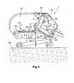
- Figs. 3 and 4 illustrate an alternative embodiment.
- the piston/cylinder element 4 is situated, with respect to the guide arm 20, on the same side of the plane extending through the first pivot axis 22 and orthogonally to the soil surface.
- the piston/cylinder element 4 by the end 15 of the cylinder 13, is pivotably hinged in the first pivot hinge 26 at the tool holder 38, and the piston/cylinder element 4 has the end of the piston rod 12 that is located outside the cylinder 13 pivotably supported in a third pivot hinge 17 at a pivot arm 14.
- the pivot arm 14 is fastened to the axis 16.
- the axis 16 runs parallel to the soil surface and orthogonally to the travelling direction A and is coupled to the machine frame 36.
- the pivot arm 14 may be pivoted with the axis 16 relative to the machine frame 36.
- the helical springs 6, 8 are interchanged with respect to the embodiment in Figs. 1 and 2 . i.e., the helical spring 8 is arranged between the end 15 of the cylinder 13 and the annular disk 10 of the piston 12, and the helical spring 6 is located between the annular disc 10 and the end 11 of the cylinder 12.
- the piston/cylinder element 4 exerts a pressure force on the tool holder 38 that generates the moment on the penetration tool 30 that is opposite to the restoring moment.
- Both helical springs 6, 8 act as compression springs.
- the force F 1 of the helical spring 8 is greater than the force F 2 of the helical spring 6.
- the helical springs 6, 8 cause a pressure force to be exerted on the tool holder 38 that generates the moment opposite to the restoring moment on the penetration tool 30.
- the piston/cylinder element 4 exerts a tensile force on the tool holder 38 that generates the restoring moment acting on the penetration tool 30.
- the force F 2 of the helical spring 6 is greater than the force F 1 of the helical spring 8.
- each guide arm 20 with both a piston/cylinder element 4 of Fig. 1 and a second piston/cylinder element 4 of Fig. 4 , whose forces and moments add to each other.
- a piston/cylinder element 4 of Fig. 1 or Fig. 4 in combination with a spring damper element as is known from prior art, which exerts a restoring moment on the penetration tool during the entire working cycle.
Landscapes
- Life Sciences & Earth Sciences (AREA)
- Engineering & Computer Science (AREA)
- Mechanical Engineering (AREA)
- Soil Sciences (AREA)
- Environmental Sciences (AREA)
- Investigation Of Foundation Soil And Reinforcement Of Foundation Soil By Compacting Or Drainage (AREA)
- Earth Drilling (AREA)
Claims (15)
- Fahrbare Bodenbelüftungsvorrichtung (1), mit- einem Maschinenrahmen (36),- einem Antrieb,- mindestens einem von dem Antrieb auf- und abbewegten und mit dem Maschinenrahmen (36) gelenkig gekoppelten Stechwerkzeug (30), wobei das Stechwerkzeug (30) in den Boden (28) einstechbar und wieder herausziehbar ist,- wobei während einer Einstechphase, in der sich das Stechwerkzeug (30) innerhalb des Bodens (28) befindet, das Stechwerkzeug (30) relativ zu dem Maschinenrahmen (36) verschwenkbar ist,- wobei sich das Stechwerkzeug (30) vor dem Einstechen in einer Ausgangslage unter einem vorgegebenen Einstechwinkel befindet, und- wobei zumindest nach dem Herausziehen des Stechwerkzeugs (30) aus dem Boden (28) mindestens ein an dem Stechwerkzeug (30) angreifendes und mit dem Maschinenrahmen (36) gekoppeltes Element ein Rückstellmoment auf das Stechwerkzeug (30) ausübt, um das Stechwerkzeug (30) wieder in die Ausgangslage zurückzuschwenken,dadurch gekennzeichnet,
dass das an dem Stechwerkzeug (30) angreifende mindestens eine Element oder mindestens ein an dem Stechwerkzeug angreifendes zweites Element, zumindest während eines Teils der Phase, in der sich das Stechwerkzeug (30) innerhalb des Bodens (28) befindet, ein dem Rückstellmoment entgegengerichtetes Moment auf das Stechwerkzeug (30) ausübt. - Bodenbelüftungsvorrichtung (1) nach Anspruch 1, gekennzeichnet durch- mindestens einen von dem Antrieb auf- und abbewegten und an dem Maschinenrahmen (36) schwenkbar angeordneten Führungsarm (20) mit mindestens einem gelenkig mit dem Führungsarm (20) gekoppelten Stechwerkzeug (30), wobei das Stechwerkzeug (30) in den Boden (28) einstechbar und wieder herausziehbar ist, und- einen Werkzeughalter (38) für das Stechwerkzeug (30), der um eine erste Schwenkachse (22) in dem von dem Antrieb auf- und abbewegbaren Führungsarm (20) gelagert ist, um während einer Einstechphase, in der sich das Stechwerkzeug (30) innerhalb des Bodens (28) befindet, ein Verschwenken des Stechwerkzeugs (30) relativ zu dem Führungsarm (20) zu ermöglichen,- wobei sich das Stechwerkzeug (30) vor dem Einstechen in einer Ausgangslage unter einem vorgegebenen Einstechwinkel befindet, und- wobei zumindest nach dem Herausziehen des Stechwerkzeugs (30) aus dem Boden (28) mindestens ein an dem Werkzeughalter (38) angreifendes Element ein Rückstellmoment auf das Stechwerkzeug (30) ausübt, um das Stechwerkzeug (30) wieder in die Ausgangslage zurückzuschwenken.
- Bodenbelüftungsvorrichtung (1) nach Anspruch 1 oder 2, dadurch gekennzeichnet, dass sich die Übergänge zwischen der Phase, in der das Element ein Rückstellmoment auf das Stechwerkzeug (30) ausübt, und der Phase, in der das Element ein dem Rückstellmoment entgegengerichtetes Moment auf das Stechwerkzeug (30) ausübt, innerhalb der Einstechphase befinden, und dass das Element zu den Zeitpunkten der Phasenübergänge innerhalb eines Arbeitszyklus kein Moment auf das Stechwerkzeug (30) ausübt.
- Bodenbelüftungsvorrichtung (1) nach einem der Ansprüche 1 bis 3, dadurch gekennzeichnet, dass die Zeitpunkte der Phasenübergänge, an denen das Element kein Moment auf das Stechwerkzeug (30) ausübt, einstellbar sind.
- Bodenbelüftungsvorrichtung (1) nach einem der Ansprüche 1 bis 4, dadurch gekennzeichnet, dass die Länge der Phase, in der das Element ein dem Rückstellmoment entgegengerichtetes Moment auf das Stechwerkzeug (30) ausübt, einstellbar ist.
- Bodenbelüftungsvorrichtung (1) nach einem der Ansprüche 1 bis 5, dadurch gekennzeichnet, dass das Element hydraulisch, pneumatisch, elektromagnetisch oder mechanisch antreibbar ist.
- Bodenbelüftungsvorrichtung (1) nach einem der Ansprüche 1 bis 6, dadurch gekennzeichnet, dass das Element aus einem Kraftelement besteht, das während der Phase, in der ein dem Rückstellmoment entgegengerichtetes Moment auf das Stechwerkzeug (30) einwirkt, eine Druck- oder Zugkraft auf das Stechwerkzeug (30) ausübt, die das Moment erzeugt.
- Bodenbelüftungsvorrichtung (1) nach Anspruch 7, dadurch gekennzeichnet, dass das Kraftelement aus einem Kolben-Zylinderelement (4), das mit dem Stechwerkzeug (30) und dem Maschinenrahmen (36) gekoppelt ist, besteht.
- Bodenbelüftungsvorrichtung (1) nach Anspruch 8, dadurch gekennzeichnet, dass das Kolben-Zylinderelement (4) mindestens einen Kolben und mindestens ein Federelement aufweist.
- Bodenbelüftungsvorrichtung (1) nach einem der Ansprüche 7 bis 9, dadurch gekennzeichnet, dass das Kraftelement aus zwei Schraubenfedern (6,8) besteht.
- Bodenbelüftungsvorrichtung (1) nach Anspruch 10, dadurch gekennzeichnet, dass die zwei Schraubenfedern (6,8) in Reihe geschaltet sind.
- Bodenbelüftungsvorrichtung (1) nach Anspruch 10 oder 11, dadurch gekennzeichnet, dass die beiden Schraubenfedern (6,8) vorspannbar sind.
- Bodenbelüftungsvorrichtung (1) nach einem der Ansprüche 7 bis 12, dadurch gekennzeichnet, dass durch Verschwenken eines Schwenkarms (20) bezogen auf den Maschinenrahmen (36) die Zeitpunkte der Phasenübergänge, an denen das Kraftelement kein Moment auf das Stechwerkzeug (30) ausübt, einstellbar sind.
- Bodenbelüftungsvorrichtung (1) nach Anspruch 13, dadurch gekennzeichnet, dass durch Verschwenken des Schwenkarms (20) bezogen auf den Maschinenrahmen (36) die Vorspannung der Schraubenfedern (6,8) einstellbar ist.
- Verfahren zum Einstechen von Stechwerkzeugen (30) in den Boden (28) bei einer Bodenbelüftungsvorrichtung (1), indem- mindestens ein mit der Bodenbelüftungsvorrichtung (1) gelenkig gekoppeltes Stechwerkzeug (30) auf- und abbewegt wird, wobei das Stechwerkzeug (30) in den Boden (28) eingestochen und wieder herausgezogen wird,- wobei das Stechwerkzeug (30) während einer Einstechphase, in der sich das Stechwerkzeug (30) innerhalb des Bodens (28) befindet, relativ zu dem Führungsarm (20) verschwenkt wird,- wobei das Stechwerkzeug (30) vor dem Einstechen in eine Ausgangslage unter einem vorgegebenen Einstechwinkel gebracht wird, und- wobei zumindest nach dem Herausziehen des Stechwerkzeugs (30) aus dem Boden (28) ein Rückstellmoment auf das Stechwerkzeug (30) ausgeübt wird, um das Stechwerkzeug (30) wieder in die Ausgangslage zurückzuschwenken,dadurch gekennzeichnet,
dass zumindest während eines Teils der Phase, in der sich das Stechwerkzeug (30) innerhalb des Bodens (28) befindet, ein dem Rückstellmoment entgegengerichtetes Moment auf das Stechwerkzeug (30) ausgeübt wird.
Priority Applications (4)
| Application Number | Priority Date | Filing Date | Title |
|---|---|---|---|
| EP08156823.0A EP2123143B1 (de) | 2008-05-23 | 2008-05-23 | Bodenbelüftungsvorrichtung und Verfahren zum Einstossen von Eindringwerkzeugen in den Boden |
| ES08156823.0T ES2439952T3 (es) | 2008-05-23 | 2008-05-23 | Dispositivo de aireación del suelo y método para empujar herramientas de penetración dentro del suelo |
| US12/992,056 US8485272B2 (en) | 2008-05-23 | 2009-05-19 | Soil aerating device and method for pushing penetration tools into soil |
| PCT/EP2009/056067 WO2009141345A1 (en) | 2008-05-23 | 2009-05-19 | Soil aerating device and method for pushing penetration tools into soil |
Applications Claiming Priority (1)
| Application Number | Priority Date | Filing Date | Title |
|---|---|---|---|
| EP08156823.0A EP2123143B1 (de) | 2008-05-23 | 2008-05-23 | Bodenbelüftungsvorrichtung und Verfahren zum Einstossen von Eindringwerkzeugen in den Boden |
Publications (2)
| Publication Number | Publication Date |
|---|---|
| EP2123143A1 EP2123143A1 (de) | 2009-11-25 |
| EP2123143B1 true EP2123143B1 (de) | 2013-11-06 |
Family
ID=39767198
Family Applications (1)
| Application Number | Title | Priority Date | Filing Date |
|---|---|---|---|
| EP08156823.0A Active EP2123143B1 (de) | 2008-05-23 | 2008-05-23 | Bodenbelüftungsvorrichtung und Verfahren zum Einstossen von Eindringwerkzeugen in den Boden |
Country Status (4)
| Country | Link |
|---|---|
| US (1) | US8485272B2 (de) |
| EP (1) | EP2123143B1 (de) |
| ES (1) | ES2439952T3 (de) |
| WO (1) | WO2009141345A1 (de) |
Families Citing this family (7)
| Publication number | Priority date | Publication date | Assignee | Title |
|---|---|---|---|---|
| US8977441B2 (en) * | 2011-06-28 | 2015-03-10 | Caterpillar Inc. | Method and system for calculating and displaying work tool orientation and machine using same |
| DE202012010495U1 (de) * | 2012-11-05 | 2014-02-14 | Redexim Handel- En Exploitatie Maatschappij B.V. | Bodenbearbeitungsvorrichtung zum Erzeugen von Hohlräumen in einem Boden |
| EP2745665B1 (de) * | 2012-12-21 | 2020-04-22 | Redexim Handel-en Exploitatie Maatschappij B.V. | Bodenbearbeitungsvorrichtung zum Bearbeiten von Bodenflächen sowie ein Verfahren zum Bearbeiten von Bodenflächen |
| EP2754343B1 (de) * | 2013-01-15 | 2017-11-01 | Redexim Handel-en Exploitatie Maatschappij B.V. | Fahrbare bodenbearbeitungsvorrichtung mit schutzeinrichtung |
| WO2014145656A1 (en) | 2013-03-15 | 2014-09-18 | Aeromax, Llc | Tine holding apparatus and method for aearating soil |
| EP2944167B1 (de) * | 2014-05-16 | 2018-11-28 | Redexim Handel- En Exploitatie Maatschappij B.V. | Bodenbearbeitungsvorrichtung |
| CN110687013A (zh) * | 2019-10-21 | 2020-01-14 | 成都理工大学 | 一种多角度、多速度贯入受力试验装置及方法 |
Family Cites Families (21)
| Publication number | Priority date | Publication date | Assignee | Title |
|---|---|---|---|---|
| US3022834A (en) * | 1959-07-13 | 1962-02-27 | William A Ruka | Turf and lawn cultivator |
| US3163236A (en) * | 1962-10-30 | 1964-12-29 | John C Ray | Soil spiking machine |
| US3163235A (en) * | 1962-10-30 | 1964-12-29 | John C Ray | Sod spiking machine |
| US3878899A (en) * | 1972-02-23 | 1975-04-22 | Richard M Jones | Lawn cultivator |
| NL8001412A (nl) * | 1980-03-10 | 1980-12-31 | J De Ridder Fa | Inrichting voor het aanbrengen van vertikale draineerkanalen in grasvelden, weilanden enz. |
| US5570746A (en) * | 1993-03-15 | 1996-11-05 | Southern Green, Inc. | Turf aeration device |
| IT1285464B1 (it) * | 1996-02-22 | 1998-06-08 | Franco Selvatici | Apparecchiatura per il trattamento del terreno |
| DE19655123C2 (de) * | 1996-07-31 | 2000-03-09 | Wiedenmann Gmbh | Bearbeitungsgerät für die Tiefenlockerung von Böden |
| NL1004926C2 (nl) * | 1997-01-03 | 1998-07-06 | Redexim Handel En Expl Mij Bv | Inrichting voor het beluchten van een bodemlaag. |
| GB2333219B (en) * | 1998-01-14 | 2002-10-16 | Turfmech Machinery Ltd | Aeration machine |
| DE50312022D1 (de) * | 2002-05-15 | 2009-11-26 | Wiedenmann Gmbh | Bodenbearbeitungsgerät |
| NL1028670C2 (nl) * | 2005-04-01 | 2006-10-03 | Redexim Handel En Expl Mij Bv | Beluchtingsinrichting. |
| DE102005021025B4 (de) | 2005-04-01 | 2012-02-16 | Wiedenmann Gmbh | Bodenbearbeitungsgerät |
| DE102005055289B3 (de) * | 2005-11-21 | 2007-03-22 | Wiedenmann Gmbh | Bodenbearbeitungsgerät mit Kurbelschutz |
| NL1031566C2 (nl) * | 2006-04-11 | 2007-10-12 | Redexim Handel En Expl Mij Bv | Beluchtingsinrichting. |
| NL1031747C2 (nl) * | 2006-05-04 | 2007-11-06 | Redexim Handel En Expl Mij Bv | Beluchtingsinrichting. |
| WO2008101292A1 (en) * | 2007-02-22 | 2008-08-28 | Greencare Industries Pty Ltd | 'aerator mechanism with vertically reciprocating tine' |
| EP1967055A1 (de) * | 2007-03-06 | 2008-09-10 | Redexim Handel-en Exploitatie Maatschappij B.V. | Bodenbearbeitungsvorrichtung |
| ATE544331T1 (de) * | 2007-07-12 | 2012-02-15 | Redexim Handel En Expl Mij Bv | Bodenbearbeitungsvorrichtung |
| DE102008017242B4 (de) * | 2008-03-10 | 2011-12-22 | Wiedenmann Gmbh | Bodenbearbeitungsgerät |
| DK2106679T3 (en) * | 2008-04-01 | 2015-11-23 | Redexim Handel En Expl Mij Bv | Device for aeration of soil |
-
2008
- 2008-05-23 ES ES08156823.0T patent/ES2439952T3/es active Active
- 2008-05-23 EP EP08156823.0A patent/EP2123143B1/de active Active
-
2009
- 2009-05-19 WO PCT/EP2009/056067 patent/WO2009141345A1/en active Application Filing
- 2009-05-19 US US12/992,056 patent/US8485272B2/en active Active
Also Published As
| Publication number | Publication date |
|---|---|
| US20110061880A1 (en) | 2011-03-17 |
| US8485272B2 (en) | 2013-07-16 |
| WO2009141345A1 (en) | 2009-11-26 |
| EP2123143A1 (de) | 2009-11-25 |
| ES2439952T3 (es) | 2014-01-27 |
Similar Documents
| Publication | Publication Date | Title |
|---|---|---|
| EP2123143B1 (de) | Bodenbelüftungsvorrichtung und Verfahren zum Einstossen von Eindringwerkzeugen in den Boden | |
| AU2008200825B2 (en) | A soil working device | |
| US6003613A (en) | Apparatus for aerating a ground layer | |
| US8602120B2 (en) | Soil working device | |
| EP2120526B1 (de) | Vertikutiermechanismus mit sich vertikal hin und her bewegendem zinken | |
| CN106961906B (zh) | 马铃薯收获机薯土分离调节装置 | |
| US9357687B2 (en) | Apparatus and method for aerating soil | |
| CA2895563C (en) | Tilling device for tilling ground surfaces, and a method for tilling ground surfaces | |
| US8616296B2 (en) | Soil aeration device | |
| US20020189825A1 (en) | Reciprocating drive mechanism for a turf aerator | |
| EP1713317A1 (de) | Belüftungsvorrichtung und verfahren zur bodenbelüftung | |
| WO2001047341A1 (en) | Reciprocating drive mechanism for a turf aerator | |
| WO2002094000A1 (en) | Improved aerator mechanism | |
| US20170094888A1 (en) | Soil processing device | |
| JP2000060238A (ja) | 苗移植機 | |
| JPS5853317Y2 (ja) | 耕盤の破砕装置 | |
| CN116584222A (zh) | 一种插秧机的送秧板快速固定装置 | |
| AU2330501A (en) | Reciprocating drive mechanism for a turf aerator |
Legal Events
| Date | Code | Title | Description |
|---|---|---|---|
| PUAI | Public reference made under article 153(3) epc to a published international application that has entered the european phase |
Free format text: ORIGINAL CODE: 0009012 |
|
| AK | Designated contracting states |
Kind code of ref document: A1 Designated state(s): AT BE BG CH CY CZ DE DK EE ES FI FR GB GR HR HU IE IS IT LI LT LU LV MC MT NL NO PL PT RO SE SI SK TR |
|
| AX | Request for extension of the european patent |
Extension state: AL BA MK RS |
|
| 17P | Request for examination filed |
Effective date: 20100514 |
|
| 17Q | First examination report despatched |
Effective date: 20100611 |
|
| AKX | Designation fees paid |
Designated state(s): AT BE BG CH CY CZ DE DK EE ES FI FR GB GR HR HU IE IS IT LI LT LU LV MC MT NL NO PL PT RO SE SI SK TR |
|
| GRAP | Despatch of communication of intention to grant a patent |
Free format text: ORIGINAL CODE: EPIDOSNIGR1 |
|
| INTG | Intention to grant announced |
Effective date: 20130531 |
|
| RIN1 | Information on inventor provided before grant (corrected) |
Inventor name: DE BREE, CORNELIUS, HERMANUS, MARIA |
|
| GRAS | Grant fee paid |
Free format text: ORIGINAL CODE: EPIDOSNIGR3 |
|
| GRAA | (expected) grant |
Free format text: ORIGINAL CODE: 0009210 |
|
| AK | Designated contracting states |
Kind code of ref document: B1 Designated state(s): AT BE BG CH CY CZ DE DK EE ES FI FR GB GR HR HU IE IS IT LI LT LU LV MC MT NL NO PL PT RO SE SI SK TR |
|
| REG | Reference to a national code |
Ref country code: GB Ref legal event code: FG4D |
|
| REG | Reference to a national code |
Ref country code: CH Ref legal event code: EP |
|
| REG | Reference to a national code |
Ref country code: AT Ref legal event code: REF Ref document number: 638792 Country of ref document: AT Kind code of ref document: T Effective date: 20131215 |
|
| REG | Reference to a national code |
Ref country code: IE Ref legal event code: FG4D |
|
| REG | Reference to a national code |
Ref country code: CH Ref legal event code: NV Representative=s name: ISLER AND PEDRAZZINI AG, CH |
|
| REG | Reference to a national code |
Ref country code: DE Ref legal event code: R096 Ref document number: 602008028505 Country of ref document: DE Effective date: 20140102 |
|
| REG | Reference to a national code |
Ref country code: ES Ref legal event code: FG2A Ref document number: 2439952 Country of ref document: ES Kind code of ref document: T3 Effective date: 20140127 |
|
| REG | Reference to a national code |
Ref country code: NL Ref legal event code: T3 |
|
| REG | Reference to a national code |
Ref country code: AT Ref legal event code: MK05 Ref document number: 638792 Country of ref document: AT Kind code of ref document: T Effective date: 20131106 |
|
| REG | Reference to a national code |
Ref country code: LT Ref legal event code: MG4D |
|
| PG25 | Lapsed in a contracting state [announced via postgrant information from national office to epo] |
Ref country code: NO Free format text: LAPSE BECAUSE OF FAILURE TO SUBMIT A TRANSLATION OF THE DESCRIPTION OR TO PAY THE FEE WITHIN THE PRESCRIBED TIME-LIMIT Effective date: 20140206 Ref country code: LT Free format text: LAPSE BECAUSE OF FAILURE TO SUBMIT A TRANSLATION OF THE DESCRIPTION OR TO PAY THE FEE WITHIN THE PRESCRIBED TIME-LIMIT Effective date: 20131106 Ref country code: FI Free format text: LAPSE BECAUSE OF FAILURE TO SUBMIT A TRANSLATION OF THE DESCRIPTION OR TO PAY THE FEE WITHIN THE PRESCRIBED TIME-LIMIT Effective date: 20131106 Ref country code: HR Free format text: LAPSE BECAUSE OF FAILURE TO SUBMIT A TRANSLATION OF THE DESCRIPTION OR TO PAY THE FEE WITHIN THE PRESCRIBED TIME-LIMIT Effective date: 20131106 Ref country code: SE Free format text: LAPSE BECAUSE OF FAILURE TO SUBMIT A TRANSLATION OF THE DESCRIPTION OR TO PAY THE FEE WITHIN THE PRESCRIBED TIME-LIMIT Effective date: 20131106 Ref country code: IS Free format text: LAPSE BECAUSE OF FAILURE TO SUBMIT A TRANSLATION OF THE DESCRIPTION OR TO PAY THE FEE WITHIN THE PRESCRIBED TIME-LIMIT Effective date: 20140306 |
|
| PG25 | Lapsed in a contracting state [announced via postgrant information from national office to epo] |
Ref country code: BE Free format text: LAPSE BECAUSE OF FAILURE TO SUBMIT A TRANSLATION OF THE DESCRIPTION OR TO PAY THE FEE WITHIN THE PRESCRIBED TIME-LIMIT Effective date: 20131106 Ref country code: AT Free format text: LAPSE BECAUSE OF FAILURE TO SUBMIT A TRANSLATION OF THE DESCRIPTION OR TO PAY THE FEE WITHIN THE PRESCRIBED TIME-LIMIT Effective date: 20131106 Ref country code: LV Free format text: LAPSE BECAUSE OF FAILURE TO SUBMIT A TRANSLATION OF THE DESCRIPTION OR TO PAY THE FEE WITHIN THE PRESCRIBED TIME-LIMIT Effective date: 20131106 |
|
| PG25 | Lapsed in a contracting state [announced via postgrant information from national office to epo] |
Ref country code: PT Free format text: LAPSE BECAUSE OF FAILURE TO SUBMIT A TRANSLATION OF THE DESCRIPTION OR TO PAY THE FEE WITHIN THE PRESCRIBED TIME-LIMIT Effective date: 20140306 |
|
| PG25 | Lapsed in a contracting state [announced via postgrant information from national office to epo] |
Ref country code: EE Free format text: LAPSE BECAUSE OF FAILURE TO SUBMIT A TRANSLATION OF THE DESCRIPTION OR TO PAY THE FEE WITHIN THE PRESCRIBED TIME-LIMIT Effective date: 20131106 |
|
| REG | Reference to a national code |
Ref country code: DE Ref legal event code: R097 Ref document number: 602008028505 Country of ref document: DE |
|
| PG25 | Lapsed in a contracting state [announced via postgrant information from national office to epo] |
Ref country code: CZ Free format text: LAPSE BECAUSE OF FAILURE TO SUBMIT A TRANSLATION OF THE DESCRIPTION OR TO PAY THE FEE WITHIN THE PRESCRIBED TIME-LIMIT Effective date: 20131106 Ref country code: SK Free format text: LAPSE BECAUSE OF FAILURE TO SUBMIT A TRANSLATION OF THE DESCRIPTION OR TO PAY THE FEE WITHIN THE PRESCRIBED TIME-LIMIT Effective date: 20131106 Ref country code: PL Free format text: LAPSE BECAUSE OF FAILURE TO SUBMIT A TRANSLATION OF THE DESCRIPTION OR TO PAY THE FEE WITHIN THE PRESCRIBED TIME-LIMIT Effective date: 20131106 Ref country code: RO Free format text: LAPSE BECAUSE OF FAILURE TO SUBMIT A TRANSLATION OF THE DESCRIPTION OR TO PAY THE FEE WITHIN THE PRESCRIBED TIME-LIMIT Effective date: 20131106 |
|
| PLBE | No opposition filed within time limit |
Free format text: ORIGINAL CODE: 0009261 |
|
| STAA | Information on the status of an ep patent application or granted ep patent |
Free format text: STATUS: NO OPPOSITION FILED WITHIN TIME LIMIT |
|
| PG25 | Lapsed in a contracting state [announced via postgrant information from national office to epo] |
Ref country code: DK Free format text: LAPSE BECAUSE OF FAILURE TO SUBMIT A TRANSLATION OF THE DESCRIPTION OR TO PAY THE FEE WITHIN THE PRESCRIBED TIME-LIMIT Effective date: 20131106 |
|
| 26N | No opposition filed |
Effective date: 20140807 |
|
| REG | Reference to a national code |
Ref country code: HU Ref legal event code: AG4A Ref document number: E020715 Country of ref document: HU |
|
| REG | Reference to a national code |
Ref country code: DE Ref legal event code: R097 Ref document number: 602008028505 Country of ref document: DE Effective date: 20140807 |
|
| PG25 | Lapsed in a contracting state [announced via postgrant information from national office to epo] |
Ref country code: LU Free format text: LAPSE BECAUSE OF FAILURE TO SUBMIT A TRANSLATION OF THE DESCRIPTION OR TO PAY THE FEE WITHIN THE PRESCRIBED TIME-LIMIT Effective date: 20140523 |
|
| REG | Reference to a national code |
Ref country code: CH Ref legal event code: PL |
|
| PG25 | Lapsed in a contracting state [announced via postgrant information from national office to epo] |
Ref country code: MC Free format text: LAPSE BECAUSE OF FAILURE TO SUBMIT A TRANSLATION OF THE DESCRIPTION OR TO PAY THE FEE WITHIN THE PRESCRIBED TIME-LIMIT Effective date: 20131106 Ref country code: LI Free format text: LAPSE BECAUSE OF NON-PAYMENT OF DUE FEES Effective date: 20140531 Ref country code: CH Free format text: LAPSE BECAUSE OF NON-PAYMENT OF DUE FEES Effective date: 20140531 |
|
| REG | Reference to a national code |
Ref country code: IE Ref legal event code: MM4A |
|
| PG25 | Lapsed in a contracting state [announced via postgrant information from national office to epo] |
Ref country code: SI Free format text: LAPSE BECAUSE OF FAILURE TO SUBMIT A TRANSLATION OF THE DESCRIPTION OR TO PAY THE FEE WITHIN THE PRESCRIBED TIME-LIMIT Effective date: 20131106 |
|
| PG25 | Lapsed in a contracting state [announced via postgrant information from national office to epo] |
Ref country code: IE Free format text: LAPSE BECAUSE OF NON-PAYMENT OF DUE FEES Effective date: 20140523 |
|
| REG | Reference to a national code |
Ref country code: FR Ref legal event code: PLFP Year of fee payment: 8 |
|
| PG25 | Lapsed in a contracting state [announced via postgrant information from national office to epo] |
Ref country code: MT Free format text: LAPSE BECAUSE OF FAILURE TO SUBMIT A TRANSLATION OF THE DESCRIPTION OR TO PAY THE FEE WITHIN THE PRESCRIBED TIME-LIMIT Effective date: 20131106 |
|
| REG | Reference to a national code |
Ref country code: FR Ref legal event code: PLFP Year of fee payment: 9 |
|
| PG25 | Lapsed in a contracting state [announced via postgrant information from national office to epo] |
Ref country code: BG Free format text: LAPSE BECAUSE OF FAILURE TO SUBMIT A TRANSLATION OF THE DESCRIPTION OR TO PAY THE FEE WITHIN THE PRESCRIBED TIME-LIMIT Effective date: 20131106 |
|
| PG25 | Lapsed in a contracting state [announced via postgrant information from national office to epo] |
Ref country code: GR Free format text: LAPSE BECAUSE OF FAILURE TO SUBMIT A TRANSLATION OF THE DESCRIPTION OR TO PAY THE FEE WITHIN THE PRESCRIBED TIME-LIMIT Effective date: 20140207 Ref country code: CY Free format text: LAPSE BECAUSE OF FAILURE TO SUBMIT A TRANSLATION OF THE DESCRIPTION OR TO PAY THE FEE WITHIN THE PRESCRIBED TIME-LIMIT Effective date: 20131106 |
|
| PG25 | Lapsed in a contracting state [announced via postgrant information from national office to epo] |
Ref country code: TR Free format text: LAPSE BECAUSE OF FAILURE TO SUBMIT A TRANSLATION OF THE DESCRIPTION OR TO PAY THE FEE WITHIN THE PRESCRIBED TIME-LIMIT Effective date: 20131106 |
|
| REG | Reference to a national code |
Ref country code: FR Ref legal event code: PLFP Year of fee payment: 10 |
|
| PGFP | Annual fee paid to national office [announced via postgrant information from national office to epo] |
Ref country code: ES Payment date: 20170601 Year of fee payment: 10 |
|
| REG | Reference to a national code |
Ref country code: FR Ref legal event code: PLFP Year of fee payment: 11 |
|
| REG | Reference to a national code |
Ref country code: ES Ref legal event code: FD2A Effective date: 20190913 |
|
| PG25 | Lapsed in a contracting state [announced via postgrant information from national office to epo] |
Ref country code: ES Free format text: LAPSE BECAUSE OF NON-PAYMENT OF DUE FEES Effective date: 20180524 |
|
| P01 | Opt-out of the competence of the unified patent court (upc) registered |
Effective date: 20230530 |
|
| PGFP | Annual fee paid to national office [announced via postgrant information from national office to epo] |
Ref country code: NL Payment date: 20230519 Year of fee payment: 16 Ref country code: IT Payment date: 20230531 Year of fee payment: 16 Ref country code: FR Payment date: 20230517 Year of fee payment: 16 Ref country code: DE Payment date: 20230525 Year of fee payment: 16 |
|
| PGFP | Annual fee paid to national office [announced via postgrant information from national office to epo] |
Ref country code: HU Payment date: 20230519 Year of fee payment: 16 |
|
| PGFP | Annual fee paid to national office [announced via postgrant information from national office to epo] |
Ref country code: GB Payment date: 20230522 Year of fee payment: 16 |