EP2120336B1 - Technique pour contrôler le gain d'un récepteur - Google Patents
Technique pour contrôler le gain d'un récepteur Download PDFInfo
- Publication number
- EP2120336B1 EP2120336B1 EP08008936A EP08008936A EP2120336B1 EP 2120336 B1 EP2120336 B1 EP 2120336B1 EP 08008936 A EP08008936 A EP 08008936A EP 08008936 A EP08008936 A EP 08008936A EP 2120336 B1 EP2120336 B1 EP 2120336B1
- Authority
- EP
- European Patent Office
- Prior art keywords
- signal
- controlling
- signal strength
- received signal
- gain
- Prior art date
- Legal status (The legal status is an assumption and is not a legal conclusion. Google has not performed a legal analysis and makes no representation as to the accuracy of the status listed.)
- Not-in-force
Links
- 238000000034 method Methods 0.000 title claims abstract description 50
- 238000004590 computer program Methods 0.000 claims description 8
- 230000001131 transforming effect Effects 0.000 claims description 2
- 230000001276 controlling effect Effects 0.000 description 80
- 230000005540 biological transmission Effects 0.000 description 8
- 238000005259 measurement Methods 0.000 description 7
- 230000009466 transformation Effects 0.000 description 7
- 238000004891 communication Methods 0.000 description 5
- 238000010586 diagram Methods 0.000 description 5
- 230000002265 prevention Effects 0.000 description 5
- 239000000969 carrier Substances 0.000 description 4
- 230000008859 change Effects 0.000 description 4
- 238000001914 filtration Methods 0.000 description 4
- 230000008569 process Effects 0.000 description 4
- 230000002596 correlated effect Effects 0.000 description 3
- 125000004122 cyclic group Chemical group 0.000 description 3
- 230000006870 function Effects 0.000 description 3
- 238000006243 chemical reaction Methods 0.000 description 2
- 238000005562 fading Methods 0.000 description 2
- 238000001228 spectrum Methods 0.000 description 2
- 238000013459 approach Methods 0.000 description 1
- 230000001419 dependent effect Effects 0.000 description 1
- 230000006866 deterioration Effects 0.000 description 1
- 239000000284 extract Substances 0.000 description 1
- 230000007774 longterm Effects 0.000 description 1
- 238000010295 mobile communication Methods 0.000 description 1
- 238000012986 modification Methods 0.000 description 1
- 230000004048 modification Effects 0.000 description 1
- 238000012545 processing Methods 0.000 description 1
- 230000008707 rearrangement Effects 0.000 description 1
- 230000009467 reduction Effects 0.000 description 1
- 230000011664 signaling Effects 0.000 description 1
- 238000006467 substitution reaction Methods 0.000 description 1
Images


Classifications
-
- H—ELECTRICITY
- H03—ELECTRONIC CIRCUITRY
- H03G—CONTROL OF AMPLIFICATION
- H03G3/00—Gain control in amplifiers or frequency changers without distortion of the input signal
- H03G3/20—Automatic control
- H03G3/30—Automatic control in amplifiers having semiconductor devices
- H03G3/3052—Automatic control in amplifiers having semiconductor devices in bandpass amplifiers (H.F. or I.F.) or in frequency-changers used in a (super)heterodyne receiver
- H03G3/3078—Circuits generating control signals for digitally modulated signals
Definitions
- the invention generally relates to the field of controlling a gain of a receiver.
- the invention relates to a technique for controlling a receiver gain including an initial controlling measure and at least one further controlling measure.
- GSM Global System for Mobile communications
- WCDMA Wideband Code Division Multiple Access
- AGC Automatic Gain Control
- ADC Analog-to-Digital Converters
- RSSI Received Signal Strength Indication
- AGC AGC schemes in GSM mobile terminals because the signal strength of received signal bursts is constant.
- RSSI can also be used for AGC schemes in WCDMA mobile terminals, since in WCDMA telecommunication systems more than half of the total signal strength of received signals is derived from broadcast channels having constant power levels.
- Next generation mobile terminals use Orthogonal Frequency Division Multiplex (OFDM) and similar transmission schemes such as Single-Carrier Frequency Division Multiple Access (SC-FDMA).
- OFDM Orthogonal Frequency Division Multiplex
- SC-FDMA Single-Carrier Frequency Division Multiple Access
- Such transmissions schemes are standardized by the 3rd Generation Partnership Project (3GPP) under the term “Long Term Evolution” (LTE).
- Fig. 1 shows an exemplary LTE frame structure and resource grid for an OFDM downlink transmission.
- a 10 ms radio frame is divided into 20 equally sized time slots of 0,5 ms.
- a 1 ms sub-frame consists of two consecutive time slots.
- one radio frame contains 10 subframes.
- a downlink resource grid for one downlink time slot, time slot No. 0 is shown.
- the downlink resource grid consists of sub-carrier and OFDM symbol.
- the number of sub-carriers and OFDM symbols depends on the downlink bandwidth.
- Transmission data is allocated to mobile terminals by means of resource blocks.
- One resource block consists of a plurality of resource elements as shown in Fig. 1 .
- one or more resource blocks can be allocated to a mobile terminal for each 1 ms sub-frame. This allocation is performed by a base station.
- the resource block allocation changes dynamically from sub-frame to sub-frame. Therefore, the signal strength of the received signals will also change dynamically from sub-frame to sub-frame. In particular, the signal strength may change from almost zero to full signal strength and vice versa from one sub-frame to the next sub-frame, i.e. every 1 ms. Moreover, the change of signal strength from sub-frame to sub-frame is not predictable.
- RSSI measurements are not suitable for controlling the receiver gain in LTE (and similar) mobile terminals.
- TDD-CDMA Time Division Duplex - Code Division Multiple Access
- the AGC scheme uses separate AGC processes for different stages of synchronization acquisition.
- a TDD-CDMA downlink beacon-function in particular a peak power measurement over an entire time frame, is used for AGC control.
- the beacon-function is always transmitted in a respective time slot at a known reference power level.
- the signal power received from the beacon-function is estimated by measuring the signal power received in a known midamble sequence.
- Document US 2002/0098814 A1 concerns an apparatus for providing automatic gain control for use in a satellite terminal of a satellite communication system.
- two different control schemes are disclosed, i.e., a first control scheme for an initial acquisition mode and a second control scheme for a subsequent tracking mode of operation.
- the gain control is based on a measured peak power level of a received beacon signal.
- Document EP 1401 134 A1 concerns an automatic gain control circuit.
- a demodulation apparatus comprising a burst detector having autocorrelation and cross-correlation circuits is disclosed.
- a method of controlling a receiver gain comprising the steps of receiving at least one signal, initially controlling the gain based on a correlation value of a first part of the received signal having a substantially constant signal strength, determining at least one timing-related parameter of the received signal based on the at least first part, identifying based on the at least one timing-related parameter at least a second part of the received signal having a substantially constant signal strength and further controlling the gain based on a measured signal strength of the identified second part.
- a part of the received signal as understood herein may be a subset, a signal part, a sub-signal or any other sub-entity of the received signal.
- the receiver gain is controlled based on a correlation value of a first part of the received signal having a substantially constant signal strength.
- the correlation value may be determined based on a cross-correlation of the unknown first part of the received signal with a known reference signal or a number of known reference signals. The higher the correlation value, the more similar or more congruent the target and the reference signals are.
- the receiver gain may be initially set low and thereafter increased until a peak value of the correlation value is detected. Thus, a coarse control of the receiver gain can initially be provided.
- the correlation i.e. for determining the correlation value
- only a first part of the received signal having a substantially constant signal strength and not the signal strength of the entire received signal may be used, since in LTE and similar telecommunication systems, the signal strength of the entire received signal may vary dynamically from sub-frame to sub-frame.
- At least one timing-related parameter of the received signal is determined.
- the at least one timing-related parameter By means of the at least one timing-related parameter, at least a second part of the received signal having a substantially constant signal strength can be identified.
- the signal strength of the identified second part can be measured.
- further controlling of the gain of the receiver is based on the measured signal strength of the identified second part.
- the first part of the received signal having a substantially constant signal strength may be a synchronisation signal comprising slot synchronisation information.
- the synchronisation signal may be a Primary Synchronisation Signal (P-SS) which provides the receiver with slot synchronisation information.
- P-SS Primary Synchronisation Signal
- the synchronisation signal comprising slot synchronisation information may be an LTE P-SS.
- the second part of the received signal having substantially constant signal strength may comprise at least one of a synchronisation signal comprising slot synchronisation information, a synchronisation signal comprising frame synchronisation information, a transport channel comprising system information and a reference signal comprising channel estimation information.
- the synchronisation signal comprising slot synchronisation information may be the P-SS described above.
- the P-SS signal strength may be measured and used for the further controlling of the receiver gain.
- the synchronisation signal comprising frame synchronisation information may be a Secondary Synchronisation Signal (S-SS) providing the receiver with frame synchronisation information.
- S-SS Secondary Synchronisation Signal
- the synchronisation signal comprising frame synchronisation may be an LTE S-SS.
- the transport channel comprising system information may be a Broadcast Channel (BCH) carrying system information in a cell.
- BCH Broadcast Channel
- the transport channel comprising system information may be an LTE BCH.
- the reference signal comprising channel estimation information may be a Reference Signal (RSIG).
- RSIG Reference Signal
- the reference signal comprising channel estimation information may be an LTE RSIG.
- the at least one timing-related parameter is associated with at least one of the slot timing, the frame timing and the symbol timing of the received signal.
- the location of the at least second part of the received signal may be extracted from the received signal.
- the signal strength of the second part can be measured.
- the signal strength of the second part may be measured in the time domain.
- the at least one timing-related parameter of the received signal is determined based on the first part and a further part of the received signal having a substantially constant signal strength.
- the further part may be a synchronization signal comprising frame synchronization information (e.g. S-SS) or another part of the received signal.
- the at least one timing-related parameter may be determined based on a correlation of a synchronization signal comprising slot synchronization information (e.g. P-SS) and a correlation of a synchronization signal comprising frame synchronization information (e.g. S-SS).
- the further controlling may comprise controlling the receiver gain based on a signal strength of at least one of the first part, the second part and a third part of the received signal having a substantially constant signal strength.
- the signal strength of these parts can be measured.
- any combination of the first, the second and the third part (or all three parts) can be used.
- the first part can be the synchronisation signal comprising slot synchronisation information (e.g. the P-SS)
- the second part can be the synchronisation signal comprising frame synchronisation information (e.g. the S-SS)
- the third part can be the transport channel comprising system information (e.g. the BCH).
- the receiver gain may also be further controlled after the initial controlling based on a signal strength of a further part of the received signal having a substantially constant signal strength.
- the further part may be the RSIG or a similar signal.
- the method may comprise the further step of controlling the receiver gain based on a measured signal strength of a fourth part of a received signal having a substantially constant signal strength.
- the step may be performed after the further controlling step. Thereby, fine controlling of the receiver gain can be provided.
- the fourth part may be a reference signal, e.g. the RSIG, comprising channel estimation information.
- the method may comprise the further steps of transforming the received signal into the frequency domain and identifying in the frequency domain the fourth or another part of the received signal.
- the received signal to be transformed may be a signal at full bandwidth.
- the fourth or further part of the received signal may, for example, be determined after a Fast Fourier Transformation (FFT).
- FFT Fast Fourier Transformation
- the fourth or further part is the RSIG
- the controlling of the receiver gain based on a measured signal strength of the RSIG typically provides the most accurate controlling results, since the RSIG contains all information about the channel and allows accurate estimation of the receiver gain.
- the initial controlling, the further controlling and the controlling based on a measured signal strength of the fourth part may be performed subsequent to each other.
- the further controlling and the controlling based on a measured signal strength of the fourth part may also be interchanged or combined into one controlling step.
- the receiver gain is controlled so that a target Signal-to-Noise-Ratio (SNR) value is reached.
- the target SNR value may be a minimum SNR value.
- the controlling of the gain of the receiver so that a minimum SNR value is reached may be used for the further controlling and the controlling based on a measured signal strength of the fourth part.
- the method may comprise the steps of determining the total signal strength of the received signal and controlling the receiver gain based on the determined total signal strength.
- the determining of the total signal strength of the received signal may be provided in parallel to the initial controlling, the further controlling and the controlling based on a measured signal strength of the fourth part.
- the determining of the total signal strength may be provided after the ADC.
- the received signal may be narrow band filtered before the initial controlling.
- P-SS, S-SS and BCH which are located in the narrow band, can be filtered.
- the narrow band filtering may be performed after the ADC right before the initial controlling. Independent of the narrow band filtering, the received signal having full bandwidth may still be transformed in the frequency domain for controlling the receiver gain based on a measured signal strength of a fourth part of a received signal having a substantially constant signal strength.
- the techniques presented herein can be practiced in the form of hardware, in the form of software and in the form of a combined hardware/software approach.
- a computer program product comprises program code portions for performing one or more of the steps of the methods and techniques described herein when the computer program product is run on one or more components of a network.
- the computer program product may be stored on a computer readable recording medium.
- an apparatus for controlling a gain of a receiver comprises a receiving unit for receiving at least one signal, a first controlling unit for initially controlling the gain based on a correlation value of a first part of the received signal having a substantially constant signal strength, a determining unit for determining at least one timing-related parameter of the received signal based on the at least first part, a first identifying unit for identifying based on the at least one timing-related parameter at least a second part of the received signal having a substantially constant signal strength and a second controlling unit for further controlling the gain based on a measured signal strength of the identified second part.
- the apparatus may further comprise a second identifying unit for identifying a third part of the received signal having a substantially constant signal strength, wherein the at least one timing-related parameter of the received signal is determined based on the identified first part and a further part of the received signal having a substantially constant signal strength.
- the apparatus may further comprise a third controlling unit for controlling the receiver gain based on a measured signal strength of a fourth part of the received signal having a substantially constant signal strength.
- a mobile terminal comprising an apparatus for controlling a gain of a receiver, as described herein.
- the mobile terminal may be a mobile telephone, a network or data card, a Personal Digital Assistant (PDA) or any other communication device.
- PDA Personal Digital Assistant
- a base station comprising an apparatus for controlling a gain of a receiver, as described herein, is provided.
- the base station may be a NodeB.
- Fig. 2 shows a schematic block diagram illustrating an embodiment of a communication network.
- the communication network comprises a base station 100 and a mobile terminal 130.
- Base station 100 communicates via antenna 110 with mobile terminal 130, as indicated by arrow 160.
- Mobile terminal 130 communicates via antenna 140 with base station 100.
- received signals are provided to AGC unit 120.
- AGC unit 120 controls the receiver gain of base station 100.
- received signals are provided to AGC unit 150.
- AGC unit 150 controls the receiver gain of mobile terminal 130.
- Fig. 3 shows a schematic block diagram illustrating an embodiment of an apparatus 200 for controlling a gain of a receiver.
- the receiver may, for example, be incorporated in a LTE terminal such as a mobile telephone.
- the apparatus 200 may also be the AGC unit 120 of the base station 100 and/or the AGC unit 150 of the mobile terminal 130 shown in Fig. 2 .
- the apparatus 200 is an LTE receiver comprising four control loops for controlling the gain of a receiver unit 205.
- the first control loop comprises the receiver unit 205, an ADC circuit 215, a first RSSI unit 220 and an ADC overflow prevention control unit 225.
- the second control loop is an AGC loop and comprises the receiver unit 205, the ADC circuit 215, a channel filter 240, a narrow band filter 243, a correlation unit 242 and a first control unit 245.
- the third control loop is also an AGC loop and comprises the receiver unit 205, the ADC circuit 215, the channel filter 240, a determining unit 250, a first identifying unit 252, a second RSSI unit 255 and a second control unit 260.
- the fourth control loop is a further AGC loop and comprises the receiver unit 205, the ADC circuit 215, the channel filter 240, a transformation unit 265, a second identifying unit 270, a third RSSI unit 275 and a third control unit 280.
- the ADC overflow prevention control unit 225, the first control unit 245, the second control unit 260 and the third control unit 280 are located within an AGC unit 230.
- the radio receiver unit 205 receives from an antenna (not shown) via an air interface an input signal 210.
- the signal 210 is an LTE transmission data signal including P-SS, S-SS, BCH and RSIG signal parts having a substantially constant signal strength.
- the signal 210 could additionally include further signal parts, or one or more of the P-SS, S-SS, BCH and RSIG signal parts may at least temporally not be included in the signal 210.
- the P-SS and S-SS signal parts convey network timing information and can be used by a mobile terminal during cell search procedures, i.e. after power on of the receiver and/or cell reselection.
- the P-SS is sent in slot No. 0 and slot No. 10 of a radio frame and occupies 72 sub-carriers.
- the P-SS is located in OFDM symbol 6.
- the S-SS is sent in LTE telecommunication systems in slot No. 0 and slot No. 10 of a radio frame and occupies 72 sub-carriers.
- the S-SS is located in OFDM symbol 6.
- P-SS and S-SS may be combined to form a physical cell identity, e.g. a cell specific identifier. For determining the P-SS, no knowledge regarding cell-specific parameters is necessary. However, for determining the S-SS, system knowledge regarding slot timing is necessary.
- the BCH carries system information within a cell. System information is typically required during a cell search procedure.
- the BCH is mapped onto a Physical Broadcast Channel (PBCH).
- PBCH Physical Broadcast Channel
- the PBCH is located in frame No. 1, sub-frame No. 1 in OFDM symbols 0 to 3 on 72 sub-carriers.
- For determining the BCH system knowledge regarding frame timing and symbol structure (i.e. cyclic prefix length) is necessary.
- the RSIG comprises channel estimation information.
- the RSIG may for example be located in OFDM symbols No. 0, 4, 7, 11 in each sub-frame.
- system information regarding cell bandwidth, frame timing and symbol structure i.e. cyclic prefix length is necessary.
- P-SS, S-SS and PBCH signals occupy the same frequency spectrum. However, they are non-overlapping in time. Moreover, P-SS, S-SS and PBCH together may provide frequency synchronisation. The synchronization signals may use the same type of pseudo-random sequence as the reference signal.
- Evolved Universal Terrestrial Radio Access (E-UTRA) networks are described in more detail in document 3GPP TS 36.211 V8.0.0 "3rd Generation Partnership Project; Technical Specification Group Radio Access Network; Evolved Universal Terrestrial Radio Access (E-UTRA); Physical channels and modulation (Release 8)", which is herewith incorporated by reference in its entirety.
- the received signal 210 is in an first step supplied to the ADC circuit 215 which generates an ADC signal 217.
- the first RSSI unit 220 measures the total signal strength of the ADC signal 217.
- the measurement value is provided to the ADC overflow prevention control unit 225.
- the ADC overflow prevention control unit 225 controls the gain of the receiver unit 205, i.e. provides a gain control signal 235 to the receiver unit 205, such that the gain of the receiver unit 205 is reduced as soon as the maximum power level of the ADC circuit 215 is reached. Thereby, bit overflow of the ADC circuit 215 and clipping is prevented.
- the ADC signal 217 is provided to the channel filter 240.
- Channel filter 240 removes blockers and other unwanted signals which are close to the desired signal spectrum.
- the bandwidth of the signal 241 filtered by channel filter 240 is the cell bandwidth.
- the filtered signal 241 is narrow band filtered by narrow band filter 243 and subsequently provided to the correlation unit 242.
- the correlation unit 242 generates a correlation value for the primary synchronisation signal P-SS.
- the correlation value is determined based on a cross-correlation of the P-SS with a known P-SS reference signal. The higher the correlation value, the more similar the P-SS and the P-SS reference signal are.
- the determined correlation value is subsequently provided to the first control unit 245.
- the first control unit 245 initially controls the gain of the receiver unit 205, i.e. provides a gain control signal 235 to the receiver unit 205.
- a coarse control of the receiver gain during the timing acquisition phase i.e. after power on of the receiver or cell reselection, of the receiver 200 is provided.
- no signal strength measurement of the P-SS may be possible, since the P-SS does not occupy the whole time axis but shares it with channels having high dynamics.
- initial control of the receiver gain based on the P-SS correlation value is possible. No knowledge regarding cell-specific parameters is necessary for this initial control based on the P-SS.
- a further controlling which is providing a more exact control 235 of the gain of the receiver unit 205, is provided.
- the filtered signal 241 is provided to the determining unit 250 which is determining at least one timing-related parameter of the filtered signal 241.
- the determining unit 250 determines the coarse frame timing of the filtered signal 241 based on the correlated P-SS.
- the determining unit 250 may as well determine the at least one timing-related parameter of the filtered signal 241 based on two or more parts of the filtered signal 241 having a substantially constant signal strength.
- the timing-related parameter may be determined based on the correlated primary and secondary synchronisation signals P-SS and S-SS.
- the timing-related parameter may also comprise slot timing and/or symbol timing.
- the first identifying unit 252 identifies at least a second part of the received signal having a substantially constant signal strength based on the at least one timing-related parameter determined by the determining unit 250.
- the first identifying unit 252 may be a filter unit.
- the determining unit 250 and the first identifying unit 252 may also be interchanged.
- the first identifying unit 252 identifies at least a second part of the received signal having a substantially constant signal strength before the determining unit 250 determines the frame timing.
- the BCH is identified by the first identifying unit 252 by means of the determined frame timing.
- the second RSSI unit 255 measures the signal strength of the BCH.
- the measured signal strength of the BCH is provided to the second control unit 260.
- the second control unit 260 controls the gain of the receiver unit 205, i.e. provides a gain control signal 235 to the receiver unit 205, based on the BCH signal strength measured by the second RSSI unit 255.
- the second RSSI unit 255 may alternatively or additionally measure the signal strength of P-SS and/or S-SS.
- the first identifying unit 252 alternatively or additionally identifies P-SS and/or S-SS and the second control unit 260 controls 235 the gain of the receiver unit 205 based on the signal strength of at least one of BCH, P-SS and S-SS.
- the filtered signal 241 is provided to the transformation unit 265.
- the transformation unit 265 is providing an OFDM demodulation using a FFT.
- the OFDM symbol timing has to be known. Accordingly, a determination of the OFDM symbol timing (not shown in Fig. 3 ) may be provided prior to the transformation into the frequency domain.
- the transformed signal 267 is provided to the second identifying unit 270.
- the second identifying unit 270 may be a filter unit.
- the second identifying unit 270 extracts the RSIG from the transformed signal 267.
- the third RSSI unit 275 measures the signal strength of the RSIG extracted by the second identifying unit 270.
- the measured signal strength of the RSIG is provided to the third control unit 280.
- the third control unit 280 is performing a fine controlling of the gain of the receiver unit 205 based on the measured signal strength of the RSIG, i.e. is providing a gain control signal 235 to the receiver unit 205.
- the signal 267 is provided to a decoder 285 for further processing.
- the first control unit 245, the second control unit 260 and the third control unit 280 perform subsequent controlling, i.e. coarse, further and fine controlling, of the gain of the receiver unit 205.
- the ADC overflow prevention control unit 225 controls in parallel the gain of the receiver unit 205 so that ADC bit overflow and clipping is prevented.
- the second 260 and the third 280 control unit i.e. the further and the fine controlling, may also be combined or interchanged. It is also possible that in addition to the first control unit 245, only one of the second control unit 260 and the third control unit 280 is provided.
- the second control unit 260 may control the gain of the receiver unit 205 so that a minimum SNR value of the receiver unit 205 is reached.
- the receiver gain is controlled so that a constant offset to the ADC limit values is provided.
- the receiver gain is controlled in that the average signal power of the receiver is provided with a constant power level below the ADC peak power level.
- the received signal power is controlled with respect to an ADC peak level, e.g. the ADC Most Significant Bit (ADC MSB).
- ADC MSB ADC Most Significant Bit
- the second control unit 260 may control the gain of the receiver unit 205 so that a minimum SNR value of the receiver unit 205 is reached.
- the received signal power may be controlled with respect to an ADC bottom level, e.g. the ADC Least Significant Bit (ADC LSB).
- ADC LSB ADC Least Significant Bit
- the second control unit 260 only considers a part or parts of the received signal having substantially constant signal strength which are identified by the first identifying unit 252 and not the entire signal.
- the third control unit 280 may also control the gain of the receiver unit 205 so that a minimum SNR value of the receiver unit 205 is reached. Thereby, the risk of clipping is reduced and the ADC bits are used in an efficient way.
- the target SNR value may be chosen such that a maximum SNR value among all physical channels which have to be decoded in a certain time frame is reached.
- signal strength measurements of parts of the received signal having a substantially constant signal strength may be combined.
- the measured signal strengths of P-SS, S-SS and BCH may be combined.
- a combination of P-SS, S-SS and BCH includes interference signals from other cells.
- the signal path comprising the narrow band filter 243, the correlation unit 242 and the first control unit 245 and the signal path comprising the determining unit 250, the first identifying unit 252, the second RSSI unit 255 and the second control unit 260 may be combined.
- one filter unit which is capable of providing several filtering functions, e.g. P-SS and S-SS filtering, may be provided for both circuit paths.
- the one filter unit may provide the filtered, i.e. the extracted signal, to the correlation unit 242 and the second RSSI unit 255 for subsequent controlling of the receiver gain in the respective control units 245 and 260.
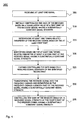
- Fig. 4 shows a flow chart illustrating a method embodiment of a method for controlling a gain of a receiver.
- the method 300 may be practiced by the apparatus 200 shown in Fig. 3 or by any other apparatus requiring AGC.
- the method starts in step 305 by receiving at least one signal by a receiver.
- the signal may be received via an air interface from a base station.
- the gain of the receiver is initially controlled based on a correlation value of a first part of a received signal having a substantially constant signal strength.
- the initial controlling may be based on a correlation value of P-SS.
- step 315 at least one timing-related parameter of the received signal is determined based on the at least first part. For example, based on the correlated P-SS value, the frame timing of the received signal may be determined.
- At least one timing-related parameter at least a second part of the received signal having a substantially constant signal strength is identified in step 320. For example, based on the frame timing, the BCH, the P-SS or the S-SS may be determined.
- a further controlling of the gain of the receiver is provided in step 325.
- the gain of the receiver is controlled based on a measured signal strength of the identified second part.
- the further controlling 325 may be based on a measured signal strength of the P-SS, the S-SS and/or the BCH.
- the received signal is transformed in step 330 into the frequency domain and a fourth part of the received signal having a substantially constant signal strength is determined.
- the RSIG may be identified in the frequency domain.
- the gain of the receiver is fine controlled based on a measured signal strength of the fourth part of the received signal having a substantially constant signal strength, as indicated in step 335.
- the gain of the receiver may be fine controlled based on the measured signal strength of the RSIG.
- a technique for controlling a gain of a receiver which is receiving shared channels having high dynamics is provided.
- the technique is based on a multi step approach. Dependent on which system parameters are available in a certain control phase, each control step may make use of different system parameters. Only parts of a received downlink signal that are transmitted with a substantially constant signal strength (and not the entire downlink signal) are considered for the controlling of the receiver gain. Thus, slow path loss variations caused by shadowing are compensated. The technique does not react on fast fading. Thus, the stability and robustness of the controlling of the receiver gain is improved, in particular in comparison with conventional concepts that attempt to track the fast fading process of AGC schemes. Furthermore, the system parameters are exploited in an efficient way. ADC bits are used efficiently and ADC bit overflow and clipping is prevented.
- the proposed technique for controlling a gain of a receiver is explained by means of a LTE mobile terminal, in particular a LTE receiver in a LTE telecommunication system, the proposed technique is not limited to LTE telecommunication system. In principle, the proposed technique may be used in any other telecommunication system having dynamically varying input signals. Moreover, while the embodiments focus on OFDM-based downlink transmission, the present technique can also be used in an uplink direction (e.g., in a base station receiver) in which, in LTE and similar systems, SC-FDMA is used.
Claims (20)
- Procédé de contrôle d'un gain d'un récepteur, comprenant les étapes consistant à :- recevoir (305) au moins un signal ;- effectuer une corrélation croisée d'une première partie inconnue du signal reçu ayant une intensité de signal substantiellement constante avec un signal de référence connu ou un certain nombre de signaux de référence connus afin d'obtenir une valeur de corrélation ;- initialement, pendant une phase d'acquisition de temporisation du récepteur, contrôler (310) le gain sur la base de la valeur de corrélation ;- déterminer (315) au moins un paramètre relatif à la temporisation du signal reçu sur la base d'au moins la première partie ;- identifier (320) sur la base d'au moins un paramètre relatif à la temporisation au moins une seconde partie du signal reçu ayant une intensité de signal substantiellement constante ; et- contrôler davantage (325) le gain sur la base d'une intensité de signal mesurée de la seconde partie identifiée.
- Procédé selon la revendication 1, dans lequel la première partie du signal reçu est un signal de synchronisation comprenant une information de synchronisation de créneau temporel.
- Procédé selon la revendication 1 ou 2, dans lequel la seconde partie la seconde partie du signal reçu comprend au moins un d'un signal de synchronisation comprenant une information de synchronisation de créneau temporel, un signal de synchronisation comprenant une information de synchronisation de trame, un canal de transport comprenant une information de système et un signal de référence comprenant une information d'estimation de canal.
- Procédé selon une quelconque des revendications précédentes, dans lequel le au moins un paramètre relatif à la temporisation est associé à au moins une d'une temporisation de créneau temporel, une temporisation de trame et une temporisation de symbole du signal reçu.
- Procédé selon une quelconque des revendications précédentes, dans lequel le au moins un paramètre relatif à la synchronisation du signal reçu est déterminé sur la base de la première partie et d'une autre partie du signal reçu ayant une intensité de signal substantiellement constante.
- Procédé selon une quelconque des revendications précédentes, dans lequel le contrôle supplémentaire (325) comprend de contrôler le gain sur la base d'une intensité de signal mesurée d'au moins une de la première partie, la seconde partie et une troisième partie du signal reçu ayant une intensité de signal substantiellement constante.
- Procédé selon une quelconque des revendications précédentes, comprenant en outre l'étape consistant à :- contrôler (330) le gain sur la base d'une intensité de signal mesurée d'une quatrième partie du signal reçu ayant une intensité de signal substantiellement constante.
- Procédé selon la revendication 7, dans lequel le contrôle initial (310), le contrôle supplémentaire (325) et le contrôle (330) basé sur une intensité de signal mesurée de la quatrième partie sont effectués l'un à la suite de l'autre.
- Procédé selon une quelconque des revendications précédentes, comprenant en outre les étapes consistant à :- transformer (335) le signal reçu en le domaine de fréquence ; et- identifier dans le domaine de fréquence la quatrième ou une autre partie du signal reçu ayant une intensité de signal substantiellement constante.
- Procédé selon une quelconque des revendications précédentes, dans lequel le gain est contrôlé de sortie qu'une valeur de rapport signal sur bruit (SNR) cible soit atteinte.
- Procédé selon la revendication 10, dans lequel la valeur de rapport signal sur bruit (SNR) cible est une valeur de rapport signal sur bruit (SNR) minimale.
- Procédé selon une quelconque des revendications précédentes, comprenant en outre les étapes consistant à :- déterminer une intensité de signal totale du signal reçu ; et- contrôler le gain sur la base de l'intensité de signal totale déterminée.
- Procédé selon une quelconque des revendications précédentes, dans lequel le signal reçu est filtré sur bande étroite avant le contrôle initial.
- Produit de programme informatique incluant des portions de code de programme pour mettre en oeuvre les étapes de procédé selon une des revendications précédentes, quand le produit de programme informatique est exécuté sur un ou plusieurs composants d'un réseau.
- Produit de programme informatique selon la revendication 14, mémorisé sur un support d'enregistrement lisible par ordinateur.
- Appareil (200) pour contrôler un gain d'un récepteur comprenant :- une unité de réception (205) pour recevoir au moins un signal ;- une unité de corrélation (242) pour effectuer une corrélation croisée d'une première partie inconnue du signal reçu ayant une intensité de signal substantiellement constante avec un signal de référence connu ou un certain nombre de signaux de référence connus afin d'obtenir une valeur de corrélation ;- une première unité de contrôle (245) pour contrôler initialement, pendant une phase d'acquisition de temporisation du récepteur, le gain sur la base de la valeur de corrélation ;- une unité de détermination (250) pour déterminer au moins un paramètre relatif à la temporisation du signal reçu sur la base de la au moins première partie ;- une première unité d'identification (252) pour identifier sur la base d'au moins un paramètre relatif à la temporisation au moins une seconde partie du signal reçu ayant une intensité de signal substantiellement constante ; et- une seconde unité de contrôle (260) pour contrôler davantage le gain sur la base d'une intensité de signal mesurée de la seconde partie identifiée.
- Appareil selon la revendication 16, comprenant en outre .- une seconde unité d'identification (270) pour identifier une troisième partie du signal reçu ayant une intensité de signal substantiellement constante, dans lequel le au moins un paramètre relatif à la temporisation du signal reçu est déterminé sur la base de la première partie identifiée et d'une autre partie du signal reçu ayant une intensité de signal substantiellement constante.
- Appareil selon la revendication 16 ou 17, comprenant en outre .- une troisième unité de contrôle (280) pour contrôler le gain sur la base d'une intensité de signal mesurée d'une quatrième partie du signal reçu ayant une intensité de signal substantiellement constante.
- Terminal mobile (130) comprenant l'appareil selon une quelconque des revendications 16 à 18.
- Station de base (100) comprenant l'appareil selon une quelconque des revendications 16 à 18.
Priority Applications (6)
| Application Number | Priority Date | Filing Date | Title |
|---|---|---|---|
| DE602008001789T DE602008001789D1 (de) | 2008-05-14 | 2008-05-14 | Verfahren zur Steuerung einer Empfängerverstärkung |
| EP08008936A EP2120336B1 (fr) | 2008-05-14 | 2008-05-14 | Technique pour contrôler le gain d'un récepteur |
| AT08008936T ATE474374T1 (de) | 2008-05-14 | 2008-05-14 | Verfahren zur steuerung einer empfängerverstärkung |
| CN200980117840.3A CN102027674B (zh) | 2008-05-14 | 2009-05-08 | 用于控制接收器的增益的技术 |
| PCT/EP2009/055584 WO2009138361A1 (fr) | 2008-05-14 | 2009-05-08 | Technique pour contrôler le gain d'un récepteur |
| US12/991,076 US20110134980A1 (en) | 2008-05-14 | 2009-05-08 | Technique for Controlling a Gain of a Receiver |
Applications Claiming Priority (1)
| Application Number | Priority Date | Filing Date | Title |
|---|---|---|---|
| EP08008936A EP2120336B1 (fr) | 2008-05-14 | 2008-05-14 | Technique pour contrôler le gain d'un récepteur |
Publications (2)
| Publication Number | Publication Date |
|---|---|
| EP2120336A1 EP2120336A1 (fr) | 2009-11-18 |
| EP2120336B1 true EP2120336B1 (fr) | 2010-07-14 |
Family
ID=39752530
Family Applications (1)
| Application Number | Title | Priority Date | Filing Date |
|---|---|---|---|
| EP08008936A Not-in-force EP2120336B1 (fr) | 2008-05-14 | 2008-05-14 | Technique pour contrôler le gain d'un récepteur |
Country Status (6)
| Country | Link |
|---|---|
| US (1) | US20110134980A1 (fr) |
| EP (1) | EP2120336B1 (fr) |
| CN (1) | CN102027674B (fr) |
| AT (1) | ATE474374T1 (fr) |
| DE (1) | DE602008001789D1 (fr) |
| WO (1) | WO2009138361A1 (fr) |
Families Citing this family (13)
| Publication number | Priority date | Publication date | Assignee | Title |
|---|---|---|---|---|
| CN102724450B (zh) * | 2012-04-16 | 2018-01-02 | 中兴通讯股份有限公司 | 电视无线广播信号的接收方法及装置 |
| US8830859B2 (en) * | 2012-05-10 | 2014-09-09 | Blackberry Limited | Power based gain control adjustment |
| US9622230B2 (en) * | 2012-05-17 | 2017-04-11 | Qualcomm Incorporated | Narrow band partitioning and efficient resource allocation for low cost user equipments |
| US9451569B1 (en) * | 2012-09-18 | 2016-09-20 | Marvell International Ltd. | Systems and methods for detecting a primary synchronization signal in a wireless communication system |
| CN103841633B (zh) * | 2012-11-27 | 2017-08-08 | 中兴通讯股份有限公司 | 一种td‑lte自动增益控制方法及设备 |
| BR112015013880A2 (pt) * | 2012-12-14 | 2017-07-11 | Ericsson Telefon Ab L M | controle de ganho automático em uma rede de comunicação móvel heterogênea |
| JP6307662B2 (ja) | 2014-09-10 | 2018-04-04 | テレフオンアクチーボラゲット エルエム エリクソン(パブル) | キャリアアグリゲーションのための無線受信機 |
| US9474014B2 (en) * | 2014-12-23 | 2016-10-18 | Intel Corporation | Method of processing received digitized signals and mobile radio communication terminal device |
| US10263630B2 (en) * | 2016-08-11 | 2019-04-16 | Cirrus Logic, Inc. | Multi-path analog front end with adaptive path |
| US10726873B2 (en) * | 2018-08-14 | 2020-07-28 | Cirrus Logic, Inc. | Polymorphic playback system with signal detection filters of different latencies |
| US11438697B2 (en) | 2019-06-07 | 2022-09-06 | Cirrus Logic, Inc. | Low-latency audio output with variable group delay |
| US10701486B1 (en) | 2019-06-07 | 2020-06-30 | Cirrus Logic, Inc. | Low-latency audio output with variable group delay |
| CN114900402B (zh) * | 2022-05-13 | 2024-05-03 | 苏州才豪电子科技有限公司 | 一种基于智慧管理的信息控制系统 |
Family Cites Families (15)
| Publication number | Priority date | Publication date | Assignee | Title |
|---|---|---|---|---|
| US6904273B2 (en) | 2001-01-10 | 2005-06-07 | Hughes Electronics Corporation | Method and system for automatic gain control in a satellite communications system |
| US7151740B2 (en) * | 2001-02-28 | 2006-12-19 | Cingular Wireless Ii, Llc | Transmit power control for an OFDM-based wireless communication system |
| FI113513B (fi) * | 2001-03-05 | 2004-04-30 | Nokia Corp | Referenssiarvon määrittäminen pakettkytkentäiseen tiedonsiirtoverkkoon yhteydessä olevan vastaanottimen AGC-ohjausta varten |
| US7499508B2 (en) * | 2001-04-03 | 2009-03-03 | Agere Systems Inc. | Method and apparatus for adjusting the gain of an if amplifier in a communication system |
| JP3636145B2 (ja) * | 2001-06-15 | 2005-04-06 | ソニー株式会社 | 復調タイミング生成回路および復調装置 |
| JP3599001B2 (ja) * | 2001-06-25 | 2004-12-08 | ソニー株式会社 | 自動利得制御回路およびその方法、並びにそれらを用いた復調装置 |
| GB2378328B (en) * | 2001-08-01 | 2005-07-13 | Ipwireless Inc | AGC scheme and receiver for use in a wireless communication system |
| US8320301B2 (en) * | 2002-10-25 | 2012-11-27 | Qualcomm Incorporated | MIMO WLAN system |
| US20040081131A1 (en) * | 2002-10-25 | 2004-04-29 | Walton Jay Rod | OFDM communication system with multiple OFDM symbol sizes |
| US7349503B2 (en) * | 2003-11-07 | 2008-03-25 | Atheros Communications, Inc. | Adaptive interference immunity control |
| US7127223B2 (en) * | 2004-09-09 | 2006-10-24 | Navini Networks, Inc. | Proactive gain control system for communications receivers |
| KR101002872B1 (ko) * | 2005-02-07 | 2010-12-21 | 삼성전자주식회사 | 직교 주파수 분할 다중 접속 시스템에서 자동 이득 조정 장치 및 방법 |
| US7916798B2 (en) * | 2005-08-18 | 2011-03-29 | Realtek Semiconductor Corp. | Automatic gain control for frequency-hopped OFDM |
| US7881411B2 (en) * | 2006-05-05 | 2011-02-01 | Wi-Lan, Inc. | Modulation dependent automatic gain control |
| US8213556B1 (en) * | 2007-05-07 | 2012-07-03 | Marvell International Ltd. | Signal power estimation for cellular OFDM systems |
-
2008
- 2008-05-14 AT AT08008936T patent/ATE474374T1/de not_active IP Right Cessation
- 2008-05-14 DE DE602008001789T patent/DE602008001789D1/de active Active
- 2008-05-14 EP EP08008936A patent/EP2120336B1/fr not_active Not-in-force
-
2009
- 2009-05-08 CN CN200980117840.3A patent/CN102027674B/zh not_active Expired - Fee Related
- 2009-05-08 US US12/991,076 patent/US20110134980A1/en not_active Abandoned
- 2009-05-08 WO PCT/EP2009/055584 patent/WO2009138361A1/fr active Application Filing
Also Published As
| Publication number | Publication date |
|---|---|
| EP2120336A1 (fr) | 2009-11-18 |
| ATE474374T1 (de) | 2010-07-15 |
| DE602008001789D1 (de) | 2010-08-26 |
| CN102027674B (zh) | 2014-07-09 |
| CN102027674A (zh) | 2011-04-20 |
| US20110134980A1 (en) | 2011-06-09 |
| WO2009138361A1 (fr) | 2009-11-19 |
Similar Documents
| Publication | Publication Date | Title |
|---|---|---|
| EP2120336B1 (fr) | Technique pour contrôler le gain d'un récepteur | |
| US8462647B2 (en) | Method and system for multiple frequency hypothesis testing with full synch acquisition in an E-UTRA/LTE UE receiver | |
| US8401123B2 (en) | Method and system for increasing the accuracy of frequency offset estimation in multiple frequency hypothesis testing in an E-UTRA/LTE UE receiver | |
| JP5345156B2 (ja) | 時分割多重ダウンリンク/アップリンク構成の検出 | |
| US9215712B2 (en) | Method and system for iterative multiple frequency hypothesis testing with Cell-ID detection in an E-UTRA/LTE UE receiver | |
| US8576830B2 (en) | Method and system for tracking timing drift in multiple frequency hypothesis testing | |
| US9369978B2 (en) | Method and system for implementing multiple timing domains for primary and secondary synchronization detection in EUTRA/LTE | |
| US8948156B2 (en) | Method and system for generating timed events in a radio frame in an E-UTRA/LTE UE receiver | |
| US8797965B2 (en) | Technique for automatic gain control in a multi-carrier communication system | |
| US7415083B2 (en) | AGC scheme and receiver for use in a wireless communication system | |
| US9479218B2 (en) | Methods for LTE cell search with large frequency offset | |
| KR101656083B1 (ko) | 근거리 무선 통신 시스템에서의 수신 동기 획득 방법 및 그 장치 | |
| CN108605304B (zh) | 采用降低的采样率的NB-IoT装置中的下行链路时间跟踪 | |
| KR20100014196A (ko) | Ofdm 심볼 동기 및 추적을 위한 참조 신호(rs) 타이밍 루프에 대한 방법 및 시스템 | |
| US8055252B2 (en) | Adaptive cell ID detection in a cellular communications system | |
| US20130230012A1 (en) | Determining a mobile communications network cell frequency | |
| US20110243105A1 (en) | Method and system for automatically rescaling an accumulation buffer in synchronization systems | |
| KR20050018296A (ko) | 직교 주파수 분할 다중 방식 통신 시스템에서 파일럿송수신 장치 및 방법 |
Legal Events
| Date | Code | Title | Description |
|---|---|---|---|
| PUAI | Public reference made under article 153(3) epc to a published international application that has entered the european phase |
Free format text: ORIGINAL CODE: 0009012 |
|
| 17P | Request for examination filed |
Effective date: 20090512 |
|
| AK | Designated contracting states |
Kind code of ref document: A1 Designated state(s): AT BE BG CH CY CZ DE DK EE ES FI FR GB GR HR HU IE IS IT LI LT LU LV MC MT NL NO PL PT RO SE SI SK TR |
|
| AX | Request for extension of the european patent |
Extension state: AL BA MK RS |
|
| GRAP | Despatch of communication of intention to grant a patent |
Free format text: ORIGINAL CODE: EPIDOSNIGR1 |
|
| GRAS | Grant fee paid |
Free format text: ORIGINAL CODE: EPIDOSNIGR3 |
|
| GRAA | (expected) grant |
Free format text: ORIGINAL CODE: 0009210 |
|
| AK | Designated contracting states |
Kind code of ref document: B1 Designated state(s): AT BE BG CH CY CZ DE DK EE ES FI FR GB GR HR HU IE IS IT LI LT LU LV MC MT NL NO PL PT RO SE SI SK TR |
|
| REG | Reference to a national code |
Ref country code: GB Ref legal event code: FG4D |
|
| REG | Reference to a national code |
Ref country code: CH Ref legal event code: EP |
|
| AKX | Designation fees paid |
Designated state(s): AT BE BG CH CY CZ DE DK EE ES FI FR GB GR HR HU IE IS IT LI LT LU LV MC MT NL NO PL PT RO SE SI SK TR |
|
| REG | Reference to a national code |
Ref country code: IE Ref legal event code: FG4D |
|
| REF | Corresponds to: |
Ref document number: 602008001789 Country of ref document: DE Date of ref document: 20100826 Kind code of ref document: P |
|
| REG | Reference to a national code |
Ref country code: NL Ref legal event code: VDEP Effective date: 20100714 |
|
| LTIE | Lt: invalidation of european patent or patent extension |
Effective date: 20100714 |
|
| PG25 | Lapsed in a contracting state [announced via postgrant information from national office to epo] |
Ref country code: NO Free format text: LAPSE BECAUSE OF FAILURE TO SUBMIT A TRANSLATION OF THE DESCRIPTION OR TO PAY THE FEE WITHIN THE PRESCRIBED TIME-LIMIT Effective date: 20101014 Ref country code: AT Free format text: LAPSE BECAUSE OF FAILURE TO SUBMIT A TRANSLATION OF THE DESCRIPTION OR TO PAY THE FEE WITHIN THE PRESCRIBED TIME-LIMIT Effective date: 20100714 Ref country code: FI Free format text: LAPSE BECAUSE OF FAILURE TO SUBMIT A TRANSLATION OF THE DESCRIPTION OR TO PAY THE FEE WITHIN THE PRESCRIBED TIME-LIMIT Effective date: 20100714 Ref country code: LT Free format text: LAPSE BECAUSE OF FAILURE TO SUBMIT A TRANSLATION OF THE DESCRIPTION OR TO PAY THE FEE WITHIN THE PRESCRIBED TIME-LIMIT Effective date: 20100714 Ref country code: NL Free format text: LAPSE BECAUSE OF FAILURE TO SUBMIT A TRANSLATION OF THE DESCRIPTION OR TO PAY THE FEE WITHIN THE PRESCRIBED TIME-LIMIT Effective date: 20100714 |
|
| PG25 | Lapsed in a contracting state [announced via postgrant information from national office to epo] |
Ref country code: SI Free format text: LAPSE BECAUSE OF FAILURE TO SUBMIT A TRANSLATION OF THE DESCRIPTION OR TO PAY THE FEE WITHIN THE PRESCRIBED TIME-LIMIT Effective date: 20100714 Ref country code: IS Free format text: LAPSE BECAUSE OF FAILURE TO SUBMIT A TRANSLATION OF THE DESCRIPTION OR TO PAY THE FEE WITHIN THE PRESCRIBED TIME-LIMIT Effective date: 20101114 Ref country code: HR Free format text: LAPSE BECAUSE OF FAILURE TO SUBMIT A TRANSLATION OF THE DESCRIPTION OR TO PAY THE FEE WITHIN THE PRESCRIBED TIME-LIMIT Effective date: 20100714 Ref country code: PL Free format text: LAPSE BECAUSE OF FAILURE TO SUBMIT A TRANSLATION OF THE DESCRIPTION OR TO PAY THE FEE WITHIN THE PRESCRIBED TIME-LIMIT Effective date: 20100714 Ref country code: CY Free format text: LAPSE BECAUSE OF FAILURE TO SUBMIT A TRANSLATION OF THE DESCRIPTION OR TO PAY THE FEE WITHIN THE PRESCRIBED TIME-LIMIT Effective date: 20100714 Ref country code: BG Free format text: LAPSE BECAUSE OF FAILURE TO SUBMIT A TRANSLATION OF THE DESCRIPTION OR TO PAY THE FEE WITHIN THE PRESCRIBED TIME-LIMIT Effective date: 20101014 |
|
| PG25 | Lapsed in a contracting state [announced via postgrant information from national office to epo] |
Ref country code: GR Free format text: LAPSE BECAUSE OF FAILURE TO SUBMIT A TRANSLATION OF THE DESCRIPTION OR TO PAY THE FEE WITHIN THE PRESCRIBED TIME-LIMIT Effective date: 20101015 Ref country code: SE Free format text: LAPSE BECAUSE OF FAILURE TO SUBMIT A TRANSLATION OF THE DESCRIPTION OR TO PAY THE FEE WITHIN THE PRESCRIBED TIME-LIMIT Effective date: 20100714 Ref country code: LV Free format text: LAPSE BECAUSE OF FAILURE TO SUBMIT A TRANSLATION OF THE DESCRIPTION OR TO PAY THE FEE WITHIN THE PRESCRIBED TIME-LIMIT Effective date: 20100714 Ref country code: BE Free format text: LAPSE BECAUSE OF FAILURE TO SUBMIT A TRANSLATION OF THE DESCRIPTION OR TO PAY THE FEE WITHIN THE PRESCRIBED TIME-LIMIT Effective date: 20100714 |
|
| PG25 | Lapsed in a contracting state [announced via postgrant information from national office to epo] |
Ref country code: DK Free format text: LAPSE BECAUSE OF FAILURE TO SUBMIT A TRANSLATION OF THE DESCRIPTION OR TO PAY THE FEE WITHIN THE PRESCRIBED TIME-LIMIT Effective date: 20100714 |
|
| PLBE | No opposition filed within time limit |
Free format text: ORIGINAL CODE: 0009261 |
|
| STAA | Information on the status of an ep patent application or granted ep patent |
Free format text: STATUS: NO OPPOSITION FILED WITHIN TIME LIMIT |
|
| PG25 | Lapsed in a contracting state [announced via postgrant information from national office to epo] |
Ref country code: IT Free format text: LAPSE BECAUSE OF FAILURE TO SUBMIT A TRANSLATION OF THE DESCRIPTION OR TO PAY THE FEE WITHIN THE PRESCRIBED TIME-LIMIT Effective date: 20100714 Ref country code: SK Free format text: LAPSE BECAUSE OF FAILURE TO SUBMIT A TRANSLATION OF THE DESCRIPTION OR TO PAY THE FEE WITHIN THE PRESCRIBED TIME-LIMIT Effective date: 20100714 Ref country code: RO Free format text: LAPSE BECAUSE OF FAILURE TO SUBMIT A TRANSLATION OF THE DESCRIPTION OR TO PAY THE FEE WITHIN THE PRESCRIBED TIME-LIMIT Effective date: 20100714 Ref country code: EE Free format text: LAPSE BECAUSE OF FAILURE TO SUBMIT A TRANSLATION OF THE DESCRIPTION OR TO PAY THE FEE WITHIN THE PRESCRIBED TIME-LIMIT Effective date: 20100714 Ref country code: CZ Free format text: LAPSE BECAUSE OF FAILURE TO SUBMIT A TRANSLATION OF THE DESCRIPTION OR TO PAY THE FEE WITHIN THE PRESCRIBED TIME-LIMIT Effective date: 20100714 |
|
| 26N | No opposition filed |
Effective date: 20110415 |
|
| PG25 | Lapsed in a contracting state [announced via postgrant information from national office to epo] |
Ref country code: ES Free format text: LAPSE BECAUSE OF FAILURE TO SUBMIT A TRANSLATION OF THE DESCRIPTION OR TO PAY THE FEE WITHIN THE PRESCRIBED TIME-LIMIT Effective date: 20101025 |
|
| REG | Reference to a national code |
Ref country code: DE Ref legal event code: R097 Ref document number: 602008001789 Country of ref document: DE Effective date: 20110415 |
|
| PG25 | Lapsed in a contracting state [announced via postgrant information from national office to epo] |
Ref country code: MC Free format text: LAPSE BECAUSE OF NON-PAYMENT OF DUE FEES Effective date: 20110531 Ref country code: MT Free format text: LAPSE BECAUSE OF FAILURE TO SUBMIT A TRANSLATION OF THE DESCRIPTION OR TO PAY THE FEE WITHIN THE PRESCRIBED TIME-LIMIT Effective date: 20100714 |
|
| REG | Reference to a national code |
Ref country code: IE Ref legal event code: MM4A |
|
| PG25 | Lapsed in a contracting state [announced via postgrant information from national office to epo] |
Ref country code: IE Free format text: LAPSE BECAUSE OF NON-PAYMENT OF DUE FEES Effective date: 20110514 |
|
| REG | Reference to a national code |
Ref country code: CH Ref legal event code: PL |
|
| PG25 | Lapsed in a contracting state [announced via postgrant information from national office to epo] |
Ref country code: CH Free format text: LAPSE BECAUSE OF NON-PAYMENT OF DUE FEES Effective date: 20120531 Ref country code: LI Free format text: LAPSE BECAUSE OF NON-PAYMENT OF DUE FEES Effective date: 20120531 |
|
| PG25 | Lapsed in a contracting state [announced via postgrant information from national office to epo] |
Ref country code: LU Free format text: LAPSE BECAUSE OF NON-PAYMENT OF DUE FEES Effective date: 20110514 |
|
| PG25 | Lapsed in a contracting state [announced via postgrant information from national office to epo] |
Ref country code: PT Free format text: LAPSE BECAUSE OF NON-PAYMENT OF DUE FEES Effective date: 20100714 |
|
| PG25 | Lapsed in a contracting state [announced via postgrant information from national office to epo] |
Ref country code: TR Free format text: LAPSE BECAUSE OF FAILURE TO SUBMIT A TRANSLATION OF THE DESCRIPTION OR TO PAY THE FEE WITHIN THE PRESCRIBED TIME-LIMIT Effective date: 20100714 |
|
| PG25 | Lapsed in a contracting state [announced via postgrant information from national office to epo] |
Ref country code: HU Free format text: LAPSE BECAUSE OF FAILURE TO SUBMIT A TRANSLATION OF THE DESCRIPTION OR TO PAY THE FEE WITHIN THE PRESCRIBED TIME-LIMIT Effective date: 20100714 |
|
| REG | Reference to a national code |
Ref country code: DE Ref legal event code: R081 Ref document number: 602008001789 Country of ref document: DE Owner name: OPTIS WIRELESS TECHNOLOGY, LLC, PLANO, US Free format text: FORMER OWNER: TELEFONAKTIEBOLAGET LM ERICSSON (PUBL), STOCKHOLM, SE Effective date: 20140618 Ref country code: DE Ref legal event code: R082 Ref document number: 602008001789 Country of ref document: DE Representative=s name: HOFFMANN - EITLE, DE Effective date: 20140618 Ref country code: DE Ref legal event code: R082 Ref document number: 602008001789 Country of ref document: DE Representative=s name: GRUENECKER, KINKELDEY, STOCKMAIR & SCHWANHAEUS, DE Effective date: 20140618 Ref country code: DE Ref legal event code: R082 Ref document number: 602008001789 Country of ref document: DE Representative=s name: GRUENECKER PATENT- UND RECHTSANWAELTE PARTG MB, DE Effective date: 20140618 |
|
| REG | Reference to a national code |
Ref country code: DE Ref legal event code: R082 Ref document number: 602008001789 Country of ref document: DE Representative=s name: GRUENECKER, KINKELDEY, STOCKMAIR & SCHWANHAEUS, DE Ref country code: DE Ref legal event code: R082 Ref document number: 602008001789 Country of ref document: DE Representative=s name: GRUENECKER PATENT- UND RECHTSANWAELTE PARTG MB, DE |
|
| REG | Reference to a national code |
Ref country code: FR Ref legal event code: PLFP Year of fee payment: 8 |
|
| REG | Reference to a national code |
Ref country code: GB Ref legal event code: 732E Free format text: REGISTERED BETWEEN 20150528 AND 20150603 |
|
| REG | Reference to a national code |
Ref country code: FR Ref legal event code: TP Owner name: OPTIS WIRELESS TECHNOLOGY, LLC, US Effective date: 20151223 |
|
| REG | Reference to a national code |
Ref country code: FR Ref legal event code: PLFP Year of fee payment: 9 |
|
| REG | Reference to a national code |
Ref country code: FR Ref legal event code: PLFP Year of fee payment: 10 |
|
| PGFP | Annual fee paid to national office [announced via postgrant information from national office to epo] |
Ref country code: DE Payment date: 20170420 Year of fee payment: 10 Ref country code: FR Payment date: 20170421 Year of fee payment: 10 Ref country code: GB Payment date: 20170426 Year of fee payment: 10 |
|
| REG | Reference to a national code |
Ref country code: DE Ref legal event code: R119 Ref document number: 602008001789 Country of ref document: DE |
|
| GBPC | Gb: european patent ceased through non-payment of renewal fee |
Effective date: 20180514 |
|
| PG25 | Lapsed in a contracting state [announced via postgrant information from national office to epo] |
Ref country code: DE Free format text: LAPSE BECAUSE OF NON-PAYMENT OF DUE FEES Effective date: 20181201 Ref country code: GB Free format text: LAPSE BECAUSE OF NON-PAYMENT OF DUE FEES Effective date: 20180514 Ref country code: FR Free format text: LAPSE BECAUSE OF NON-PAYMENT OF DUE FEES Effective date: 20180531 |