EP2120020A1 - In-flow determination of left and right eigenvectors in a coriolis flowmeter - Google Patents
In-flow determination of left and right eigenvectors in a coriolis flowmeter Download PDFInfo
- Publication number
- EP2120020A1 EP2120020A1 EP08170888A EP08170888A EP2120020A1 EP 2120020 A1 EP2120020 A1 EP 2120020A1 EP 08170888 A EP08170888 A EP 08170888A EP 08170888 A EP08170888 A EP 08170888A EP 2120020 A1 EP2120020 A1 EP 2120020A1
- Authority
- EP
- European Patent Office
- Prior art keywords
- conduit
- flow
- relative phase
- eigenvector
- determining
- Prior art date
- Legal status (The legal status is an assumption and is not a legal conclusion. Google has not performed a legal analysis and makes no representation as to the accuracy of the status listed.)
- Granted
Links
Images


Classifications
-
- G—PHYSICS
- G01—MEASURING; TESTING
- G01F—MEASURING VOLUME, VOLUME FLOW, MASS FLOW OR LIQUID LEVEL; METERING BY VOLUME
- G01F1/00—Measuring the volume flow or mass flow of fluid or fluent solid material wherein the fluid passes through a meter in a continuous flow
- G01F1/76—Devices for measuring mass flow of a fluid or a fluent solid material
- G01F1/78—Direct mass flowmeters
- G01F1/80—Direct mass flowmeters operating by measuring pressure, force, momentum, or frequency of a fluid flow to which a rotational movement has been imparted
- G01F1/84—Coriolis or gyroscopic mass flowmeters
-
- G—PHYSICS
- G01—MEASURING; TESTING
- G01F—MEASURING VOLUME, VOLUME FLOW, MASS FLOW OR LIQUID LEVEL; METERING BY VOLUME
- G01F1/00—Measuring the volume flow or mass flow of fluid or fluent solid material wherein the fluid passes through a meter in a continuous flow
- G01F1/76—Devices for measuring mass flow of a fluid or a fluent solid material
- G01F1/78—Direct mass flowmeters
- G01F1/80—Direct mass flowmeters operating by measuring pressure, force, momentum, or frequency of a fluid flow to which a rotational movement has been imparted
- G01F1/84—Coriolis or gyroscopic mass flowmeters
- G01F1/845—Coriolis or gyroscopic mass flowmeters arrangements of measuring means, e.g., of measuring conduits
- G01F1/8468—Coriolis or gyroscopic mass flowmeters arrangements of measuring means, e.g., of measuring conduits vibrating measuring conduits
- G01F1/849—Coriolis or gyroscopic mass flowmeters arrangements of measuring means, e.g., of measuring conduits vibrating measuring conduits having straight measuring conduits
-
- G—PHYSICS
- G01—MEASURING; TESTING
- G01F—MEASURING VOLUME, VOLUME FLOW, MASS FLOW OR LIQUID LEVEL; METERING BY VOLUME
- G01F1/00—Measuring the volume flow or mass flow of fluid or fluent solid material wherein the fluid passes through a meter in a continuous flow
- G01F1/76—Devices for measuring mass flow of a fluid or a fluent solid material
- G01F1/78—Direct mass flowmeters
- G01F1/80—Direct mass flowmeters operating by measuring pressure, force, momentum, or frequency of a fluid flow to which a rotational movement has been imparted
- G01F1/84—Coriolis or gyroscopic mass flowmeters
- G01F1/8409—Coriolis or gyroscopic mass flowmeters constructional details
- G01F1/8436—Coriolis or gyroscopic mass flowmeters constructional details signal processing
-
- G—PHYSICS
- G01—MEASURING; TESTING
- G01F—MEASURING VOLUME, VOLUME FLOW, MASS FLOW OR LIQUID LEVEL; METERING BY VOLUME
- G01F25/00—Testing or calibration of apparatus for measuring volume, volume flow or liquid level or for metering by volume
- G01F25/10—Testing or calibration of apparatus for measuring volume, volume flow or liquid level or for metering by volume of flowmeters
Definitions
- the invention is related to the field of flow meters, and in particular, to Coriolis flow meters.
- Mass flow rate is measured in a Coriolis flow meter by vibrating a fluid-carrying tube(s) in a sinusoidal motion and measuring the time delay (or phase angle) between the vibration response at two or more locations on the tube(s).
- time delay or phase angle
- the time delay varies linearly with mass flow rate, however, the time delay is generally not zero at zero mass flow.
- This zero-flow offset is typically corrected for by measuring the zero-flow offset at the zero-flow condition and subtracting the measured offset from subsequent measurements made during flow. This would be sufficient to correct for the zero-flow offset problem if the zero-flow offset remained constant.
- the zero-flow offset can be affected by small changes in the ambient environment (such as temperature) or to changes in the piping system through which the material is flowing. The changes in the zero-flow offset will cause errors in the measured flow rates. During normal operations, there may be long periods of time between no-flow conditions. The Coriolis flow meter can be calibrated by zeroing the meter only during these no-flow conditions. The changes in the zero-offset over time may cause significant errors in the measured flow.
- a method and apparatus that enables the periodic calculation of the relative phase of the left eigenvector for a vibrating conduit.
- two drivers are used in tandem to excite the main bending mode of the conduit. Periodically, first one, then the second, of the two drivers is disabled, allowing measurements that enable the determination of the relative phase of the left eigenvector for the vibrating conduit.
- One aspect of the invention includes, a method, comprising:
- the method further comprises:
- the method further comprises:
- the method further comprises:
- the method further comprises:
- the method further comprises:
- the method further comprises where the relative phase of the left eigenvector is corrected for a residual flexibility response and electromagnetic cross-talk.
- the method further comprises:
- Another aspect of the invention comprises:
- the method further comprises where the motion of the conduit is measured with a first sensor that is co-located with the first driver and with a second sensor that is co-located with the second driver.
- the method further comprises:
- the method further comprises:
- the method further comprises:
- the method further comprises:
- a method further comprises:
- the method further comprises where the new zero offset is determined using a relative phase of a left eigenvector for the conduit.
- the method further comprises where the new zero offset is determined periodically.
- the method further comprises where the periodicity is a function of the accuracy required in measuring the flow.
- the method further comprises where the new zero offset is determined when a change in a measured environmental parameter occurs.
- Another aspect of the invention comprises:
- the method further comprises where an actual flow of the material through the conduit is determined by using the difference in the relative phase of the left eigenvector compared to the relative phase of the right eigenvector.
- the method further comprises where a flow of the material through the conduit is determined using the relative phase of the right eigenvector corrected with a zero offset.
- the method further comprises:
- the method further comprises where an actual flow of the material through the conduit is determined by subtracting the relative phase of the left eigenvector from the relative phase of the right eigenvector; and,
- the method further comprises where the relative phase of the left eigenvector is corrected for a residual flexibility response and electromagnetic cross-talk.
- the method further comprises where a first relative phase between a first location on the vibrating conduit and a second location on the vibrating conduit is determined while exciting the vibration mode of the conduit using the at least two drivers;
- the method further comprises where the sensing apparatus comprises at least two sensors in a spaced apart relationship.
- the method further comprises where the device is a processor running code that causes the determination of the relative phase of the left and right eigenvector.
- the method further comprises where the device is a circuit that causes the determination of the relative phase of the left and right eigenvector.
- the method further comprises:
- FIGS. 1-5 and the following description depict specific examples to teach those skilled in the art how to make and use the best mode of the invention. For the purpose of teaching inventive principles, some conventional aspects have been simplified or omitted. Those skilled in the art will appreciate variations from these examples that fall within the scope of the invention. Those skilled in the art will appreciate that the features described below can be combined in various ways to form multiple variations of the invention. As a result, the invention is not limited to the specific examples described below, but only by the claims and their equivalents.
- Equation (1) M and K are the mass and stiffness matrices of the system and C is a general damping matrix which may have a symmetric component due to damping and a skew symmetric component due to Coriolis force.
- Aq + Bq u
- Equation 1 can be rewritten as equation 2 where A is equal to the matrix C M M 0 and B is equal to the matrix K 0 0 - M and u is equal to f 0 .
- Equation (2) Insight into the equation of motion can be gained by looking at equations 1 and 2.
- the eigenvector can be used to diagonalize, or decouple the equations of motion. Decoupled equations are readily solved.
- C includes the Coriolis matrix
- the right eigenvectors do not diagonalize the equations of motion, resulting in coupled equations. Coupled equations are more difficult to solve and hinder insight into the solution.
- Left eigenvectors are required to diagonalize non-symmetric A or B matrixes. The following derivations show the process.
- Equations (3) and (4) are identical and the left and right eigenvectors are the same. When there is flow the associated non-symmetry of the C matrix causes the left and right eigenvectors to be different.
- Equation (5) by ⁇ i l T
- Equations (7) and (8) show that by pre and post multiplying either of the system matrices, A or B , by the matrix of left eigenvectors, ⁇ ( L ) , and the matrix of right eigenvectors, ⁇ ( R ) , respectively, the system matrices are diagonalized.
- left and right eigenvector matrices diagonalize the system matrices means that both the set of right eigenvectors and the set of left eigenvectors are linearly independent. Either set can be used as a basis of a coordinate system for the response. Recognizing that the difference between the left and right eigenvectors is due to the non-symmetric Coriolis matrix, forms the basis of this invention.
- the mass, stiffness and damping matrices which model non-Coriolis effects are symmetric.
- the left and right eigenvectors are identical (within an arbitrary scale factor).
- the Coriolis force associated with flow manifests itself in the mathematical model as a skew symmetric damping matrix (the transpose is the negative of the original matrix).
- the skew symmetric Coriolis matrix causes the left and right eigenvectors of the system to be different.
- the relative phase between different coefficients of the left eigenvectors is equal and opposite to the relative phase between the same coefficients on the right eigenvectors.
- phase values are offset equally for both the left and right eigenvectors, however, the difference remains the same.
- this characteristic allows the phase attributable to zero-offset from non-proportional damping and the phase attributable to material flow to be distinguished, eliminating associated zero-offset errors.
- FIG. 1 shows a top view of a conduit 102 configured to contain a material flowing through the conduit.
- D1 and D2 are two drivers (also called actuators) spaced along the conduit 102. In the preferred mode the two drivers are spaced symmetrically around the axial center of the conduit.
- the drivers are configured to impart a force to the conduit 102 to excite a plurality of vibration modes in the conduit 102.
- the force may be substantially coherent (e.g. confined to a narrow frequency) or may be broadband.
- the drivers can be such known means as a magnet, attached to the conduit, and a coil, attached to a reference, through which an oscillating current is passed.
- S1 and S2 depict two sensors co-located with drivers D 1 and D2.
- the sensors are configured to produce a plurality of signals representing the location and motion of the conduit 102.
- the sensors may include a variety of devices, such as coil-type velocity transducers, optical or ultrasonic motion sensors, accelerometers, inertial rate sensors and the like. In this embodiment there are two sensors shown with each sensor co-located with one of the drivers. In other embodiments there may only be one sensor configured to measure the position and motion of the conduit 102 along the length of the conduit 102. Other configurations having more than 2 sensors are also possible.
- Figure 1A shows the conduit 102 in an un-deflected state. By driving the actuators with equal power, the main bending mode of the conduit can be excited.
- Figure 1B shows the conduit 102 in a deflected state corresponding to the main bending mode of the conduit. This vibration mode also corresponds to a condition when there is no flow of material through the conduit.
- the deflection of the conduit 102 in Figure 1B and 1C have been magnified for clarity. The actual deflections of conduit 102 would be much smaller.
- FIG. 1C shows the main vibration mode excited by the Coriolis forces.
- the relative phase difference detected between sensor S 1 and sensor S2 can be used to determine the material flow through the conduit 102. In no-flow condition (as depicted in figure 1B ) there is no phase difference due to flow, detected between S 1 and S1.There may be phase differences due to zero-offset conditions. Once material is flowing through the conduit 102 there will be a phase difference between S 1 and S2, due to flow.
- the measured phase difference detected between S 1 and S2 is a measure of the relative phase of the right eigenvector of the system and is proportional to the material flow through the conduit.
- ⁇ R the relative phase of the right eigenvector
- ⁇ S1 be the measured phase of the vibration of the conduit at sensor S1
- ⁇ S2 be the measured phase of the vibration of the conduit at sensor S2
- ⁇ R ⁇ S1 - ⁇ S2.
- a time difference, delta T can be calculated from the phase difference by dividing by the vibration frequency ⁇ .
- ⁇ T ( ⁇ S1 - ⁇ S2)/ ⁇ .
- the time difference ⁇ T is also proportional to the material flow through the conduit and is the measurement typically used in the mass flow meters.
- both drivers are used to excite the main bending mode of the conduit.
- ⁇ T RC ⁇ T R - ZeroOffset.
- the conduit is excited using only one, then the other driver. Measurements are taken between the phase of the driving signal and a position on the conduit. These measurements are used to determine the relative phase of the left eigenvector of the system.
- FIG. 2 is a flow chart for determining the left eigenvector in an example embodiment of the invention.
- both drivers are used to excite the vibration of the conduit.
- only driver D1 is used to excite the vibration of the conduit.
- the phase between the driving signal used by driver D 1 and the sensor S 1 are measured.
- the phase between the driving signal used by driver D 1 and the sensor S 1 are measured.
- driver D1 is inactivated and only driver D2 is used to excite the vibration of the conduit.
- the phase between the diving signal used by driver D2 and sensor S 1 is measured. Call this measured phase difference ⁇ 2.
- FIG. 3 is a flow chart showing one embodiment for determining the residual flexibility and electronic crosstalk.
- step 302 during normal operations, both drivers are used to excite the vibration of the conduit.
- the delta T with both drivers operating, ⁇ T D1D2 is measured between sensor S1 and sensor S1.
- driver D2 is shut off and only driver D 1 is used to excite the conduit.
- the delta T with only driver D1 operating, ⁇ T D1 is measured between sensor S1 and sensor S1.
- the difference between ⁇ T D1D2 and ⁇ T D1 is due to the residual flexibility and electronic crosstalk from driver D2.
- driver D1 is shut off and only driver D2 is used to excite the conduit.
- the delta T with only driver D2 operating, ⁇ T D2 is measured between sensor S 1 and sensor S1.
- the difference between ⁇ T D1D2 and ⁇ T D2 is due to the residual flexibility and electronic crosstalk from driver D1.
- the delta T for the relative phase of the left eigenvector ⁇ T LC can be corrected for the residual flexibility and electronic crosstalk.
- ⁇ T LC ⁇ T L - ( ⁇ T D2 - ⁇ T D1 ).
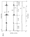
- FIG. 4 is a chart showing the relative ⁇ T values measured using an unbalanced, single tube flow meter while switching between drivers in an example embodiment of the invention.
- drivers DR1 and DR2 are oriented at 45 degrees from vertical and are located at the same axial position as sensor PR3.
- a pseudo-collocated driver/sensor pair is achieved.
- the same relationship was utilized to obtain a pseudo-collocated driver/sensor pair using drivers DL1 and DL2 and sensor PL3.
- the two driver sensor pairs (DR1/DR2/PR3 and DL1/DL2/PL3) were spaced symmetrically around the axial center of the flow meter. At time zero through time 30, both pseudo driver pairs where used to excite the vibration of the flow meter.
- the step change in ⁇ T values at approximately the 30 second point occurs when the DL1/DL2 driver pair is turned off.
- This ⁇ T change is that caused by the residual flexibility response and electromagnetic crosstalk of the DL1/DL2 pseudo driver.
- driver pair DR1/DR2 is switched off and driver pair DL1/DL2 is switched on.
- driver pair DL1/DL2 is switched on.
- the DR1/DR2 driver pair is switched back on and both pseudo driver pairs are used to excite the vibration of the flow meter.
- the change in the measured ⁇ T values between times 100 through 120 is that caused by the residual flexibility response and electromagnetic crosstalk of the DR1/DR2 pseudo driver.
- the residual flexibility and electronic crosstalk associated with each driver are equal and opposite.
- the effects cancel and generally do not have to be corrected for to accurately measure the delta T of the right eigenvector.
- the measurements for the left eigenvector and the residual flexibility and electronic crosstalk can be taken at the same time when each driver is briefly switched off.
- Compensating for non-uniform phase between different electronic measurement channels is well known in the arts.
- a known signal may be applied to the input and the phase corruption measured. This procedure can be performed during flow by providing a spare measurement channel that assumes the measurement function of the channel under test, while the test is being conducted.
- the flow effect F is the difference between the relative ⁇ T of the left and right eigenvectors divided by 2.
- F ( ⁇ T R - ⁇ T L )/2.
- a new zero offset can be calculated by comparing the flow effect F with the flow determined by measuring the ⁇ T R during normal operations.
- ZeroOffset ⁇ T R - F. The new ZeroOffset can be used to correct the measured flow during normal operations until the next time the value for the left eigenvector is determined.
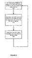
- FIG. 5 is a flow chart for recalibrating the zero offset of a flow meter during flow in one example embodiment of the current invention.
- step 502 during normal operations, both drivers are used to excite the vibration of the conduit.
- An uncorrected relative delta T for the right eigenvector is determined.
- the uncorrected relative delta T of the right eigenvector is then corrected by using a zero offset.
- the flow through the meter is determined using the corrected relative delta T of the right eigenvector.
- the drivers D1 and D2 are alternately switched off and the relative delta T of the left eigenvector and the residual flexibility (RF) and electronic crosstalk (EC) are determined.
- RF residual flexibility
- EC electronic crosstalk
- the relative delta T of the left eigenvector is corrected for the residual flexibility and electronic crosstalk effects.
- step 506 the corrected relative delta T of the left eigenvector and the uncorrected delta T of the right eigenvector are used to determine a new zero offset.
- the new zero offset is substituted for the old zero offset and the process resumes at step 502.
- the determination for when the re-calibration should occur may be done by using a fixed time interval between calibrations.
- a re-calibration may be done when changes in the environment or the piping system are detected. For example, when a change in temperature is greater than a threshold amount, a re-calibration may be performed.
- the determination for when re-calibration occurs may be a combination of a periodic timer and detecting changes in environment. The time period between recalibrations may be shorter for systems that require higher accuracy than for systems than have less stringent accuracy requirements.
- the invention was described using a single conduit flow meter. As well understood in the art, the current invention may be used in flow meters of other configurations, for example, dual conduit flow meters. The invention was also described using a straight conduit, but other configurations for the geometry of the flow meter are possible, for example a bent conduit.
Landscapes
- Physics & Mathematics (AREA)
- Fluid Mechanics (AREA)
- General Physics & Mathematics (AREA)
- Engineering & Computer Science (AREA)
- Signal Processing (AREA)
- Measuring Volume Flow (AREA)
Abstract
Description
- The invention is related to the field of flow meters, and in particular, to Coriolis flow meters.
- Mass flow rate is measured in a Coriolis flow meter by vibrating a fluid-carrying tube(s) in a sinusoidal motion and measuring the time delay (or phase angle) between the vibration response at two or more locations on the tube(s). For practical situations the time delay varies linearly with mass flow rate, however, the time delay is generally not zero at zero mass flow. There is usually a zero-flow delay or offset caused by a number of factors such as non-proportional damping, residual flexibility response, electromagnetic crosstalk, or phase delay in instrument electronics.
- This zero-flow offset is typically corrected for by measuring the zero-flow offset at the zero-flow condition and subtracting the measured offset from subsequent measurements made during flow. This would be sufficient to correct for the zero-flow offset problem if the zero-flow offset remained constant. Unfortunately, the zero-flow offset can be affected by small changes in the ambient environment (such as temperature) or to changes in the piping system through which the material is flowing. The changes in the zero-flow offset will cause errors in the measured flow rates. During normal operations, there may be long periods of time between no-flow conditions. The Coriolis flow meter can be calibrated by zeroing the meter only during these no-flow conditions. The changes in the zero-offset over time may cause significant errors in the measured flow.
- Therefore there is a need for a system and method for calibrating the zero-flow offset during flow.
- A method and apparatus is disclosed that enables the periodic calculation of the relative phase of the left eigenvector for a vibrating conduit. During normal operation, two drivers are used in tandem to excite the main bending mode of the conduit. Periodically, first one, then the second, of the two drivers is disabled, allowing measurements that enable the determination of the relative phase of the left eigenvector for the vibrating conduit. ASPECTS
- One aspect of the invention includes, a method, comprising:
- flowing a material through a conduit while exciting a vibration mode of the conduit;
- measuring the relative motion of the vibrating conduit;
- periodically determining a relative phase of a left eigenvector for the conduit.
- Preferably, the method further comprises:
- determining a relative phase of a right eigenvector for the conduit;
- determining an actual flow of the material through the conduit using the relative phase of the left eigenvector and the relative phase of the right eigenvector.
- Preferably, the method further comprises:
- determining an uncorrected flow of the material through the conduit using the relative phase of the right eigenvector;
- determining a zero offset for the flow of the material through the conduit by comparing the uncorrected flow with the actual flow.
- Preferably, the method further comprises:
- determining a material flow through the conduit using the relative phase of the right eigenvector corrected by the zero offset.
- Preferably, the method further comprises:
- determining the relative phase of a right eigenvector;
- determining a zero offset for the flow of the material through the conduit by averaging the relative phase of the right eigenvector with the relative phase of the left eigenvector.
- Preferably, the method further comprises:
- determining a material flow through the conduit using the relative phase of the right eigenvector corrected by the zero offset.
- Preferably, the method further comprises where the relative phase of the left eigenvector is corrected for a residual flexibility response and electromagnetic cross-talk.
- Preferably, the method further comprises:
- measuring a first relative phase between two spaced apart locations on the vibrating conduit while exciting the vibration mode of the conduit using both a first driver and a second driver, where the first driver is spaced apart from the second driver;
- measuring a second relative phase between the two spaced apart locations on the vibrating conduit while exciting the vibration mode of the conduit using only the second driver;
- calculating the residual flexibility response and electromagnetic cross-talk associated with the first driver by subtracting the second relative phase from the first relative phase;
- measuring a third relative phase between the two spaced apart locations on the vibrating conduit while exciting the vibration mode of the conduit using only the second driver;
- calculating the residual flexibility response and electromagnetic cross-talk associated with the second driver by subtracting the third relative phase from the first relative phase.
- Another aspect of the invention comprises:
- flowing a material through a conduit while exciting a vibration mode of the conduit using at least two drivers in a spaced apart configuration;
- measuring the motion of the vibrating conduit;
- determining a first positional relationship between a first location on the conduit and a first one of the drivers while driving the vibration mode of the conduit using only the first one of the drivers;
- determining a second positional relationship between the first location on the conduit and a second one of the drivers while driving the vibration mode of the conduit using only the second one of the drivers;
- determining a left eigenvector using the first positional relationship and the second positional relationship.
- Preferably, the method further comprises where the motion of the conduit is measured with a first sensor that is co-located with the first driver and with a second sensor that is co-located with the second driver.
- Preferably, the method further comprises:
- determining a relative phase of a right eigenvector for the conduit while exciting the vibration mode of the conduit using both the first and second drivers;
- determining an actual flow of the material through the conduit by subtracting the relative phase of the left eigenvector from the relative phase of the right eigenvector.
- Preferably, the method further comprises:
- determining an uncorrected flow of the material through the conduit using the relative phase of the right eigenvector;
- determining a zero offset for the flow of the material through the conduit by comparing the uncorrected flow with the actual flow;
- determining a material flow through the conduit using the relative phase of the right eigenvector corrected by the zero offset.
- Preferably, the method further comprises:
- determining the relative phase of a right eigenvector for the conduit while exciting the vibration mode of the conduit using both the first and second drivers;
- determining a zero offset for the flow of the material through the conduit by averaging the relative phase of the right eigenvector with the relative phase of the left eigenvector;
- determining a material flow through the conduit using the relative phase of the right eigenvector corrected by the zero offset.
- Preferably, the method further comprises:
- measuring a first delta time between the first location and a second location when driving the vibration mode using the at least two drivers;
- measuring a second delta time between the first location and the second location when driving the vibration mode using all but the first one of the drivers;
- measuring a third delta time between the first location and the second location when driving the vibration mode using all but the second one of the drivers;
- calculating a first correction value using the first delta time and the second delta time;
- calculating a second correction value using the first delta time and the third delta time;
- adjusting the first positional relationship, using the first correction value, before calculating the left eigenvector; and,
- adjusting the second positional relationship, using the second correction value, before calculating the left eigenvector.
- Preferably, a method further comprises:
- flowing a material through a conduit while exciting a vibration mode of the conduit;
- measuring the relative motion of the vibrating conduit;
- measuring a relative phase of a right eigenvector while exciting the vibration mode of the conduit;
- determining the material flow through the conduit using the relative phase of a right eigenvector corrected by a zero offset;
- determining a new zero offset without stopping the material flow through the conduit;
- determining the material flow through the conduit using the relative phase of a right eigenvector corrected by the new zero offset.
- Preferably, the method further comprises where the new zero offset is determined using a relative phase of a left eigenvector for the conduit.
- Preferably, the method further comprises where the new zero offset is determined periodically.
- Preferably, the method further comprises where the periodicity is a function of the accuracy required in measuring the flow.
- Preferably, the method further comprises where the new zero offset is determined when a change in a measured environmental parameter occurs.
- Another aspect of the invention comprises:
- a conduit configured to contain a material flowing through the conduit;
- at least two drivers configured to excite a plurality of vibration modes of the conduit;
- a sensing apparatus configured to measure the relative motion of the vibrating conduit;
- a device configured to periodically determining a relative phase of a left eigenvector for the conduit using the relative motion of the vibrating conduit;
- the device also configured to determines a relative phase of a right eigenvector for the conduit using the relative motion of the vibrating conduit.
- Preferably, the method further comprises where an actual flow of the material through the conduit is determined by using the difference in the relative phase of the left eigenvector compared to the relative phase of the right eigenvector.
- Preferably, the method further comprises where a flow of the material through the conduit is determined using the relative phase of the right eigenvector corrected with a zero offset.
- Preferably, the method further comprises:
- determining the zero offset for the flow of the material through the conduit by averaging the relative phase of the right eigenvector with the relative phase of the left eigenvector.
- Preferably, the method further comprises where an actual flow of the material through the conduit is determined by subtracting the relative phase of the left eigenvector from the relative phase of the right eigenvector; and,
- the zero offset for the flow of the material through the conduit is determined by comparing the flow determined using the relative phase of the right eigenvector with the actual flow.
- Preferably, the method further comprises where the relative phase of the left eigenvector is corrected for a residual flexibility response and electromagnetic cross-talk.
- Preferably, the method further comprises where a first relative phase between a first location on the vibrating conduit and a second location on the vibrating conduit is determined while exciting the vibration mode of the conduit using the at least two drivers;
- a second relative phase between the first location on the vibrating conduit and the second location on the vibrating conduit is determined while exciting the vibration mode of the conduit using all but a first of the at least two drivers;
- a third relative phase between the first location on the vibrating conduit and the second location on the vibrating conduit is determined while exciting the vibration mode of the conduit using all but a second of the at least two drivers; and
- the residual flexibility response and electromagnetic cross-talk for the first of the at least two drivers is determined by subtracting the second relative phase from the first relative phase;
- the residual flexibility response and electromagnetic cross-talk for the second of the at least two drivers is determined by subtracting the third relative phase from the first relative phase.
- Preferably, the method further comprises where the sensing apparatus comprises at least two sensors in a spaced apart relationship.
- Preferably, the method further comprises where the device is a processor running code that causes the determination of the relative phase of the left and right eigenvector.
- Preferably, the method further comprises where the device is a circuit that causes the determination of the relative phase of the left and right eigenvector.
- Preferably, the method further comprises:
- a conduit configured to contain a material flowing through the conduit;
- a means to excite a vibration mode of the conduit;
- a means for sensing the relative motion of the vibrating conduit;
- a means for periodically determining a relative phase of a left eigenvector for the conduit;
- a means for determining a relative phase of a right eigenvector for the conduit;
- a means for determining a zero offset for the material flowing through the conduit by averaging the relative phase of the right eigenvector with the relative phase of the left eigenvector;
- a means for determining an actual material flow by using the relative phase of the right eigenvector corrected by the zero offset.
-
-
FIG. 1A is a top view of a conduit in an un-deflected position in an example embodiment of the invention. -
FIG. 1B is a top view of a conduit in a deflected position corresponding to the main bending mode in an example embodiment of the invention. -
FIG. 1C is a top view of a conduit in a deflected position corresponding to a bending mode induced by Coriolis forces in an example embodiment of the invention. -
FIG. 2 is a flow chart for determining the left eigenvector in an example embodiment of the invention. -
FIG. 3 is a flow chart for determining the residual flexibility and electronic crosstalk in an example embodiment of the invention. -
Figure 4 is a chart showing the relative ΔTs measured using an unbalanced, single tube flow meter while switching between drivers in an example embodiment of the invention. -
FIG. 5 is a flow chart for recalibrating the zero offset of a flow meter during flow in an example embodiment of the invention. -
FIGS. 1-5 and the following description depict specific examples to teach those skilled in the art how to make and use the best mode of the invention. For the purpose of teaching inventive principles, some conventional aspects have been simplified or omitted. Those skilled in the art will appreciate variations from these examples that fall within the scope of the invention. Those skilled in the art will appreciate that the features described below can be combined in various ways to form multiple variations of the invention. As a result, the invention is not limited to the specific examples described below, but only by the claims and their equivalents. - The operation of Coriolis flow meters can be described using mathematical formulas. The general system of first order differential equations describing the motion of a linear system is:

- In Equation (1) M and K are the mass and stiffness matrices of the system and C is a general damping matrix which may have a symmetric component due to damping and a skew symmetric component due to Coriolis force.

-
Equation 1 can be rewritten asequation 2 where A is equal to the matrix
matrix 

- Insight into the equation of motion can be gained by looking at
equations 
- For symmetric A and B matrices, the eigenvector can be used to diagonalize, or decouple the equations of motion. Decoupled equations are readily solved. For a non-symmetric system, for example where C includes the Coriolis matrix, the right eigenvectors do not diagonalize the equations of motion, resulting in coupled equations. Coupled equations are more difficult to solve and hinder insight into the solution. Left eigenvectors are required to diagonalize non-symmetric A or B matrixes. The following derivations show the process. The left eigenvectors are obtained by solving the following generalized eigenvalue problem:

- M and K would generally be symmetric for a Coriolis flow meter. For no flow C would also be symmetric, thus, the system matrices, A and B would be symmetric. In this case Equations (3) and (4) are identical and the left and right eigenvectors are the same. When there is flow the associated non-symmetry of the C matrix causes the left and right eigenvectors to be different.
-

and the i'th left eigenvector;
- Pre-multiplying Equation (5) by
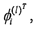


- By multiplying Equation (5) by


- Equations (7) and (8) show that by pre and post multiplying either of the system matrices, A or B, by the matrix of left eigenvectors, Φ(L), and the matrix of right eigenvectors, Φ(R), respectively, the system matrices are diagonalized.

- The fact that the left and right eigenvector matrices diagonalize the system matrices means that both the set of right eigenvectors and the set of left eigenvectors are linearly independent. Either set can be used as a basis of a coordinate system for the response. Recognizing that the difference between the left and right eigenvectors is due to the non-symmetric Coriolis matrix, forms the basis of this invention.
- In terms of a mathematical model of the meter, the mass, stiffness and damping matrices which model non-Coriolis effects are symmetric. For a no-flow system the left and right eigenvectors are identical (within an arbitrary scale factor). The Coriolis force associated with flow, however, manifests itself in the mathematical model as a skew symmetric damping matrix (the transpose is the negative of the original matrix). The skew symmetric Coriolis matrix causes the left and right eigenvectors of the system to be different. For a flowing system with no non-proportional damping the relative phase between different coefficients of the left eigenvectors is equal and opposite to the relative phase between the same coefficients on the right eigenvectors. For a system with non-proportional damping theses phase values are offset equally for both the left and right eigenvectors, however, the difference remains the same. Thus, if the phase characteristics of the left and right eigenvectors can be measured accurately this characteristic allows the phase attributable to zero-offset from non-proportional damping and the phase attributable to material flow to be distinguished, eliminating associated zero-offset errors.
- Residual flexibility, electromagnetic crosstalk and electronic measurement system characteristics also contribute to zero-offset. One interpretation of these effects is that they introduce error in the measurement of the right eigenvector phase. If the drive mode (right eigenvector) could be measured exactly, non-proportional damping would be the only effect causing zero offset and this error would be easily distinguished from flow effects using the left and right eigenvector dT information.
-
Figure 1 shows a top view of aconduit 102 configured to contain a material flowing through the conduit. D1 and D2 are two drivers (also called actuators) spaced along theconduit 102. In the preferred mode the two drivers are spaced symmetrically around the axial center of the conduit. The drivers are configured to impart a force to theconduit 102 to excite a plurality of vibration modes in theconduit 102. The force may be substantially coherent (e.g. confined to a narrow frequency) or may be broadband. The drivers can be such known means as a magnet, attached to the conduit, and a coil, attached to a reference, through which an oscillating current is passed. - S1 and S2 depict two sensors co-located with
drivers D 1 and D2. The sensors are configured to produce a plurality of signals representing the location and motion of theconduit 102. The sensors may include a variety of devices, such as coil-type velocity transducers, optical or ultrasonic motion sensors, accelerometers, inertial rate sensors and the like. In this embodiment there are two sensors shown with each sensor co-located with one of the drivers. In other embodiments there may only be one sensor configured to measure the position and motion of theconduit 102 along the length of theconduit 102. Other configurations having more than 2 sensors are also possible. -
Figure 1A shows theconduit 102 in an un-deflected state. By driving the actuators with equal power, the main bending mode of the conduit can be excited.US patent 6,092,429 granted July 25, 2000 and entitled "Driver for oscillating a vibrating conduit", which is hereby included by reference, discloses drivers configured to excite different modes of vibration in a conduit.Figure 1B shows theconduit 102 in a deflected state corresponding to the main bending mode of the conduit. This vibration mode also corresponds to a condition when there is no flow of material through the conduit. The deflection of theconduit 102 inFigure 1B and 1C have been magnified for clarity. The actual deflections ofconduit 102 would be much smaller. When material is flowing through the vibratingconduit 102, the flowing material causes Coriolis forces to be generated. The Coriolis forces deflect theconduit 102 and excite additional vibration modes.Figure 1C shows the main vibration mode excited by the Coriolis forces. The relative phase difference detected betweensensor S 1 and sensor S2 can be used to determine the material flow through theconduit 102. In no-flow condition (as depicted infigure 1B ) there is no phase difference due to flow, detected betweenS 1 and S1.There may be phase differences due to zero-offset conditions. Once material is flowing through theconduit 102 there will be a phase difference betweenS 1 and S2, due to flow. The measured phase difference detected betweenS 1 and S2 is a measure of the relative phase of the right eigenvector of the system and is proportional to the material flow through the conduit. Let θR equal the relative phase of the right eigenvector, θS1 be the measured phase of the vibration of the conduit at sensor S1, and θS2 be the measured phase of the vibration of the conduit at sensor S2, then θR = θS1 - θS2. A time difference, delta T, can be calculated from the phase difference by dividing by the vibration frequency ω. ΔT = (θS1 - θS2)/ ω. The time difference ΔT is also proportional to the material flow through the conduit and is the measurement typically used in the mass flow meters. A more accurate determination for the material flow through theconduit 102 can be calculated by correcting the measured material flow with a zero-offset amount ΔTC = ΔT - ZeroOffset. - In one example embodiment of the invention, during normal operations, both drivers are used to excite the main bending mode of the conduit. The material flow through the conduit is determined by measuring the relative phase of the right eigenvector, converting to a ΔT domain, and correcting this value with a zero-offset correction amount, ΔTRC = ΔTR - ZeroOffset. Periodically, the conduit is excited using only one, then the other driver. Measurements are taken between the phase of the driving signal and a position on the conduit. These measurements are used to determine the relative phase of the left eigenvector of the system.
-
Figure 2 is a flow chart for determining the left eigenvector in an example embodiment of the invention. Atstep 202, during normal operations, both drivers are used to excite the vibration of the conduit. Atstep 204, only driver D1 is used to excite the vibration of the conduit. During this time, the phase between the driving signal used bydriver D 1 and thesensor S 1 are measured. Call this measured phase difference θ1. Atstep 206 driver D1 is inactivated and only driver D2 is used to excite the vibration of the conduit. During this time the phase between the diving signal used by driver D2 andsensor S 1 is measured. Call this measured phase difference θ2. Atstep 208, the relative phase of the left eigenvector θL for the system may be calculated as θL = 61 - θ2. Converting to the time domain yields the relative delta T of the left eigenvector: ΔTL = (61 - θ2)/ω. Atstep 210 normal operation resumes, and both drivers are used to excite the vibration of the conduit. The sequence in which the drivers are switched on and off is not important. - Because the relative phases (θ1 and θ2) for the left eigenvector are determined when exciting the vibration of the conduit with only one driver, the residual flexibility response (RF) and electromagnetic crosstalk (EC) must be corrected. Each driver causes some residual flexibility response and electromagnetic crosstalk. This effect decays to zero almost instantaneously when the driver is shut off. By briefly shutting off a driver, the change in the measured phase at each sensor caused by the residual flexibility response and electromagnetic crosstalk associated with that driver can be determined. The change in the measured phase can be determined by measuring the step change in the difference between the sensors that occurs when each driver is inactivated.
Figure 3 is a flow chart showing one embodiment for determining the residual flexibility and electronic crosstalk. - In
step 302, during normal operations, both drivers are used to excite the vibration of the conduit. The delta T with both drivers operating, ΔTD1D2, is measured between sensor S1 and sensor S1. Atstep 304, driver D2 is shut off andonly driver D 1 is used to excite the conduit. During this time the delta T with only driver D1 operating, ΔTD1, is measured between sensor S1 and sensor S1. The difference between ΔTD1D2 and ΔTD1 is due to the residual flexibility and electronic crosstalk from driver D2. Atstep 306, driver D1 is shut off and only driver D2 is used to excite the conduit. During this time the delta T with only driver D2 operating, ΔTD2, is measured betweensensor S 1 and sensor S1. The difference between ΔTD1D2 and ΔTD2 is due to the residual flexibility and electronic crosstalk from driver D1. To correct a measured ΔT for the residual flexibility and electronic crosstalk from both drivers, the difference between ΔTD1D2 and ΔTD1 and the difference between ΔTD1D2 and ΔTD2 is subtracted from the measured ΔT. Therefore delta T corrected is ΔTC = ΔT - (ΔTD1D2 - ΔTD1) - (ΔTD1D2 - ΔTD2). Using this technique, the delta T for the relative phase of the left eigenvector ΔTLC can be corrected for the residual flexibility and electronic crosstalk. ΔTLC = ΔTL - (ΔTD2 - ΔTD1). -
Figure 4 is a chart showing the relative ΔT values measured using an unbalanced, single tube flow meter while switching between drivers in an example embodiment of the invention. On this meter, drivers DR1 and DR2 are oriented at 45 degrees from vertical and are located at the same axial position as sensor PR3. By driving DR1 and DR2 with the same signal a pseudo-collocated driver/sensor pair is achieved. The same relationship was utilized to obtain a pseudo-collocated driver/sensor pair using drivers DL1 and DL2 and sensor PL3. The two driver sensor pairs (DR1/DR2/PR3 and DL1/DL2/PL3) were spaced symmetrically around the axial center of the flow meter. At time zero through time 30, both pseudo driver pairs where used to excite the vibration of the flow meter. The step change in ΔT values at approximately the 30 second point occurs when the DL1/DL2 driver pair is turned off. This ΔT change is that caused by the residual flexibility response and electromagnetic crosstalk of the DL1/DL2 pseudo driver. At approximately time 65 driver pair DR1/DR2 is switched off and driver pair DL1/DL2 is switched on. At approximately the 100 second mark the DR1/DR2 driver pair is switched back on and both pseudo driver pairs are used to excite the vibration of the flow meter. The change in the measured ΔT values betweentimes 100 through 120 is that caused by the residual flexibility response and electromagnetic crosstalk of the DR1/DR2 pseudo driver. - For meters where the drivers and sensors are symmetrically located about the axial center of the meter, the residual flexibility and electronic crosstalk associated with each driver are equal and opposite. During normal operation, when both drivers are being used to excite the vibration of the conduit, the effects cancel and generally do not have to be corrected for to accurately measure the delta T of the right eigenvector. The measurements for the left eigenvector and the residual flexibility and electronic crosstalk can be taken at the same time when each driver is briefly switched off.
- Compensating for non-uniform phase between different electronic measurement channels is well known in the arts. For example, a known signal may be applied to the input and the phase corruption measured. This procedure can be performed during flow by providing a spare measurement channel that assumes the measurement function of the channel under test, while the test is being conducted.
- Once the relative ΔT for the left and right eigenvectors are measured and corrected for residual flexibility, electronic crosstalk effects, and the like, the contribution from flow and from non-proportional damping are calculated. The flow effect F is the difference between the relative ΔT of the left and right eigenvectors divided by 2. F = (ΔTR - ΔTL)/2. A new zero offset can be calculated by comparing the flow effect F with the flow determined by measuring the ΔTR during normal operations. ZeroOffset = ΔTR - F. The new ZeroOffset can be used to correct the measured flow during normal operations until the next time the value for the left eigenvector is determined.
- The non-proportional damping effect ND is the average of the left and right eigenvectors ND = (ΔTR + ΔTL)/2. This value could also be used as the new ZeroOffset value.
-
Figure 5 is a flow chart for recalibrating the zero offset of a flow meter during flow in one example embodiment of the current invention. In step 502, during normal operations, both drivers are used to excite the vibration of the conduit. An uncorrected relative delta T for the right eigenvector is determined. The uncorrected relative delta T of the right eigenvector is then corrected by using a zero offset. The flow through the meter is determined using the corrected relative delta T of the right eigenvector. Periodically, instep 504, the drivers D1 and D2 are alternately switched off and the relative delta T of the left eigenvector and the residual flexibility (RF) and electronic crosstalk (EC) are determined. The relative delta T of the left eigenvector is corrected for the residual flexibility and electronic crosstalk effects. Instep 506 the corrected relative delta T of the left eigenvector and the uncorrected delta T of the right eigenvector are used to determine a new zero offset. The new zero offset is substituted for the old zero offset and the process resumes at step 502. By calculating and substituting the new zero offset into the meter, the meter has been recalibrated for the zero flow condition during material flow through the meter. - In one example embodiment, the determination for when the re-calibration should occur may be done by using a fixed time interval between calibrations. In another example embodiment, a re-calibration may be done when changes in the environment or the piping system are detected. For example, when a change in temperature is greater than a threshold amount, a re-calibration may be performed. The determination for when re-calibration occurs may be a combination of a periodic timer and detecting changes in environment. The time period between recalibrations may be shorter for systems that require higher accuracy than for systems than have less stringent accuracy requirements.
- Switching between drivers D1 and D2 in order to measure the relative phase of the left eigenvector does not imply that the normal operation of the flow meter has to be interrupted (i.e. measuring flow using ΔT of the right eigenvector). For example, when the drivers are placed symmetrically about the centerline of the conduit, each driver excites the drive mode by the same amount. By, for instance, doubling the current to D2 when D1 is inactivated, the magnitude of the driving force can be maintained.
- In the descriptions above, the invention was described using a single conduit flow meter. As well understood in the art, the current invention may be used in flow meters of other configurations, for example, dual conduit flow meters. The invention was also described using a straight conduit, but other configurations for the geometry of the flow meter are possible, for example a bent conduit.
Claims (6)
- A method, comprising:flowing a material through a conduit while exciting a vibration mode of the conduit;measuring the relative motion of the vibrating conduit;measuring a relative phase of a right eigenvector while exciting the vibration mode of the conduit;determining the material flow through the conduit using the relative phase of a right eigenvector corrected by a zero offset (502) the method further characterized by:determining a new zero offset without stopping the material flow through the conduit;determining the material flow through the conduit using the relative phase of a right eigenvector corrected by the new zero offset.
- The method of claim 1 where the new zero offset is determined using a relative phase of a left eigenvector for the conduit.
- The method of claim 1 where the new zero offset is determined periodically.
- The method of claim 1 where the periodicity is a function of the accuracy required in measuring the flow.
- The method of claim 1 where the new zero offset is determined when a change in a measured environmental parameter occurs.
- An apparatus, comprising:a conduit (102) configured to contain a material flowing through the conduit;a means to excite a vibration mode of the conduit;a means for sensing the relative motion of the vibrating conduit;a means for determining a relative phase of a right eigenvector for the conduit, the apparatus further characterized by:a means for periodically determining a relative phase of a left eigenvector for the conduit;a means for determining a zero offset for the material flowing through the conduit by averaging the relative phase of the right eigenvector with the relative phase of the left eigenvector; anda means for determining an actual material flow by using the relative phase of the right eigenvector corrected by the zero offset.
Priority Applications (1)
| Application Number | Priority Date | Filing Date | Title |
|---|---|---|---|
| EP08170888.5A EP2120020B1 (en) | 2004-09-27 | 2004-09-27 | In-flow determination of left and right eigenvectors in a coriolis flowmeter |
Applications Claiming Priority (3)
| Application Number | Priority Date | Filing Date | Title |
|---|---|---|---|
| EP04785069.8A EP1794549B1 (en) | 2004-09-27 | 2004-09-27 | In-flow determination of left and right eigenvectors in a coriolis flowmeter |
| EP08170888.5A EP2120020B1 (en) | 2004-09-27 | 2004-09-27 | In-flow determination of left and right eigenvectors in a coriolis flowmeter |
| PCT/US2004/031549 WO2006036139A1 (en) | 2004-09-27 | 2004-09-27 | In-flow determination of left and right eigenvectors in a coriolis flowmeter |
Related Parent Applications (2)
| Application Number | Title | Priority Date | Filing Date |
|---|---|---|---|
| EP04785069.8A Division-Into EP1794549B1 (en) | 2004-09-27 | 2004-09-27 | In-flow determination of left and right eigenvectors in a coriolis flowmeter |
| EP04785069.8A Division EP1794549B1 (en) | 2004-09-27 | 2004-09-27 | In-flow determination of left and right eigenvectors in a coriolis flowmeter |
Publications (2)
| Publication Number | Publication Date |
|---|---|
| EP2120020A1 true EP2120020A1 (en) | 2009-11-18 |
| EP2120020B1 EP2120020B1 (en) | 2019-12-25 |
Family
ID=34958795
Family Applications (2)
| Application Number | Title | Priority Date | Filing Date |
|---|---|---|---|
| EP08170888.5A Expired - Lifetime EP2120020B1 (en) | 2004-09-27 | 2004-09-27 | In-flow determination of left and right eigenvectors in a coriolis flowmeter |
| EP04785069.8A Expired - Lifetime EP1794549B1 (en) | 2004-09-27 | 2004-09-27 | In-flow determination of left and right eigenvectors in a coriolis flowmeter |
Family Applications After (1)
| Application Number | Title | Priority Date | Filing Date |
|---|---|---|---|
| EP04785069.8A Expired - Lifetime EP1794549B1 (en) | 2004-09-27 | 2004-09-27 | In-flow determination of left and right eigenvectors in a coriolis flowmeter |
Country Status (10)
| Country | Link |
|---|---|
| US (1) | US7706987B2 (en) |
| EP (2) | EP2120020B1 (en) |
| JP (1) | JP2008514916A (en) |
| KR (1) | KR100973772B1 (en) |
| CN (1) | CN100458377C (en) |
| AR (1) | AR051036A1 (en) |
| BR (1) | BRPI0419040B1 (en) |
| CA (1) | CA2581107C (en) |
| MX (1) | MX2007003176A (en) |
| WO (1) | WO2006036139A1 (en) |
Cited By (1)
| Publication number | Priority date | Publication date | Assignee | Title |
|---|---|---|---|---|
| CN108700453A (en) * | 2016-02-26 | 2018-10-23 | 高准公司 | Determine corrected measured flow rate |
Families Citing this family (25)
| Publication number | Priority date | Publication date | Assignee | Title |
|---|---|---|---|---|
| DE102006044592A1 (en) * | 2006-09-19 | 2008-03-27 | Endress + Hauser Flowtec Ag | Method for determining the mass flow rate of a Coriolis mass flowmeter arranged on a rotary filler |
| DE102007024275A1 (en) | 2007-05-23 | 2008-11-27 | Endress + Hauser Flowtec Ag | Method for measuring and / or monitoring a flow parameter and corresponding device |
| DE102007024276A1 (en) | 2007-05-23 | 2008-11-27 | Endress + Hauser Flowtec Ag | Method for measuring and monitoring flow parameter of medium, involves exciting measuring tube to mechanical vibrations by one converter element according to one excitation signal during one measurement |
| DE102007028209A1 (en) | 2007-06-15 | 2008-12-18 | Endress + Hauser Flowtec Ag | Method for measuring and / or monitoring a flow parameter and corresponding device |
| JP5589351B2 (en) * | 2009-11-02 | 2014-09-17 | パナソニック株式会社 | Flow measuring device |
| DE102010006224A1 (en) * | 2010-01-28 | 2011-08-18 | Krohne Ag | Method for determining a parameter for the correction of measured values of a Coriolis mass flowmeter |
| DE202010009023U1 (en) * | 2010-06-12 | 2011-11-14 | Neoperl Gmbh | aerator |
| EP2771656B1 (en) | 2011-10-26 | 2018-01-24 | Micro Motion, Inc. | Collocated sensor for a vibrating fluid meter |
| EP2629066A1 (en) * | 2012-02-18 | 2013-08-21 | ABB Technology AG | Coriolis mass flow meter and signal processing method for a Coriolis mass flow meter |
| BR112015030471B1 (en) | 2013-06-14 | 2020-11-10 | Micro Motion, Inc | vibratory flow meter, and, meter verification method for vibratory flow meter |
| RU2628661C1 (en) | 2014-01-24 | 2017-08-21 | Майкро Моушн, Инк. | Vibratory flowmeter as well as methods and diagnostics for checking meter |
| DE102015107366B3 (en) * | 2015-05-11 | 2016-01-21 | Krohne Messtechnik Gmbh | Method of operating a flowmeter and related flowmeter |
| EP3329230B1 (en) * | 2015-07-27 | 2020-11-18 | Micro Motion, Inc. | Off-resonance cycling for coriolis flowmeters |
| CN107850478B (en) * | 2015-07-27 | 2020-11-10 | 高准公司 | Method for Determining Left Eigenvectors in Flow Coriolis Flow Meters |
| US11402254B2 (en) | 2019-08-13 | 2022-08-02 | Badger Meter, Inc. | Ultrasonic flow meter calibration system and method |
| EP4168752B1 (en) | 2020-06-18 | 2025-08-13 | Endress+Hauser Flowtec AG | Vibronic measuring system |
| DE102020131649A1 (en) | 2020-09-03 | 2022-03-03 | Endress + Hauser Flowtec Ag | Vibronic measuring system |
| DE102020134707A1 (en) | 2020-12-22 | 2022-06-23 | Endress+Hauser Flowtec Ag | Coriolis mass flow meter and method for determining factors influencing its total zero error, method for determining total zero error and operating method therefor |
| CN113188637B (en) * | 2021-04-30 | 2022-02-15 | 南京荣晟自动化设备有限公司 | Movable on-line calibrating device for coriolis mass flowmeter by standard meter method |
| DE102022112523A1 (en) | 2022-05-18 | 2023-11-23 | Endress+Hauser Flowtec Ag | Vibronic measuring system |
| DE102023112374A1 (en) | 2023-05-10 | 2024-11-14 | Endress+Hauser Flowtec Ag | measuring system |
| KR102749591B1 (en) | 2023-11-30 | 2025-01-07 | 주식회사 서진인스텍 | Coriolis mass flow meter measurement precision improvement device and method for improving measurement precision |
| KR102864603B1 (en) | 2023-11-30 | 2025-09-26 | 주식회사 서진인스텍 | Method for manufacturing highly reliable criolis mass flow meters |
| WO2026024305A1 (en) | 2024-07-22 | 2026-01-29 | Micro Motion, Inc. | Excitation and measurement of twist mode in a coriolis flowmeter |
| DE102024126528A1 (en) | 2024-09-13 | 2026-03-19 | Endress+Hauser Flowtec Ag | Vibronial measuring system |
Citations (2)
| Publication number | Priority date | Publication date | Assignee | Title |
|---|---|---|---|---|
| US6092429A (en) | 1997-12-04 | 2000-07-25 | Micro Motion, Inc. | Driver for oscillating a vibrating conduit |
| US6427127B1 (en) * | 1998-07-16 | 2002-07-30 | Micro Motion, Inc. | Vibrating conduit process parameter sensors, operating methods and computer program products utilizing complex modal estimation |
Family Cites Families (17)
| Publication number | Priority date | Publication date | Assignee | Title |
|---|---|---|---|---|
| USRE31450E (en) | 1977-07-25 | 1983-11-29 | Micro Motion, Inc. | Method and structure for flow measurement |
| US4365154A (en) * | 1980-03-06 | 1982-12-21 | Texaco Inc. | Detection of impurities in a fluid containing free gas using nuclear techniques |
| US4491025A (en) | 1982-11-03 | 1985-01-01 | Micro Motion, Inc. | Parallel path Coriolis mass flow rate meter |
| US5373745A (en) | 1991-02-05 | 1994-12-20 | Direct Measurement Corporation | Single path radial mode Coriolis mass flow rate meter |
| JP3200826B2 (en) | 1993-11-19 | 2001-08-20 | 横河電機株式会社 | Coriolis mass flowmeter |
| US5734112A (en) | 1996-08-14 | 1998-03-31 | Micro Motion, Inc. | Method and apparatus for measuring pressure in a coriolis mass flowmeter |
| US6199022B1 (en) | 1997-07-11 | 2001-03-06 | Micro Motion, Inc. | Drive circuit modal filter for a vibrating tube flowmeter |
| US6360175B1 (en) | 1998-02-25 | 2002-03-19 | Micro Motion, Inc. | Generalized modal space drive control system for a vibrating tube process parameter sensor |
| US5987999A (en) * | 1998-07-01 | 1999-11-23 | Micro Motion, Inc. | Sensitivity enhancing balance bar |
| US6233526B1 (en) | 1998-07-16 | 2001-05-15 | Micro Motion, Inc. | Vibrating conduit parameter sensors and methods of operation therefor utilizing spatial integration |
| US6272438B1 (en) * | 1998-08-05 | 2001-08-07 | Micro Motion, Inc. | Vibrating conduit parameter sensors, methods and computer program products for generating residual-flexibility-compensated mass flow estimates |
| US6577977B2 (en) | 1999-02-16 | 2003-06-10 | Micro Motion, Inc. | Process parameter sensor apparatus, methods and computer program products using force filtering |
| GB2350426B (en) * | 1999-05-25 | 2002-08-28 | Abb Instrumentation Ltd | Vibrating tube meter |
| US6347293B1 (en) | 1999-07-09 | 2002-02-12 | Micro Motion, Inc. | Self-characterizing vibrating conduit parameter sensors and methods of operation therefor |
| US6466880B2 (en) * | 2001-02-16 | 2002-10-15 | Micro Motion, Inc. | Mass flow measurement methods, apparatus, and computer program products using mode selective filtering |
| US6606573B2 (en) | 2001-08-29 | 2003-08-12 | Micro Motion, Inc. | Sensor apparatus, methods and computer program products employing vibrational shape control |
| US6704666B2 (en) * | 2001-08-29 | 2004-03-09 | Micro Motion, Inc. | Determining properties of a flow tube and of a fluid flowing through a flow tube of a coriolis flowmeter |
-
2004
- 2004-09-27 BR BRPI0419040A patent/BRPI0419040B1/en active IP Right Grant
- 2004-09-27 US US11/574,716 patent/US7706987B2/en not_active Expired - Lifetime
- 2004-09-27 EP EP08170888.5A patent/EP2120020B1/en not_active Expired - Lifetime
- 2004-09-27 JP JP2007533443A patent/JP2008514916A/en active Pending
- 2004-09-27 CN CNB2004800440862A patent/CN100458377C/en not_active Expired - Lifetime
- 2004-09-27 KR KR1020077009504A patent/KR100973772B1/en not_active Expired - Fee Related
- 2004-09-27 MX MX2007003176A patent/MX2007003176A/en active IP Right Grant
- 2004-09-27 CA CA2581107A patent/CA2581107C/en not_active Expired - Lifetime
- 2004-09-27 WO PCT/US2004/031549 patent/WO2006036139A1/en not_active Ceased
- 2004-09-27 EP EP04785069.8A patent/EP1794549B1/en not_active Expired - Lifetime
-
2005
- 2005-09-26 AR ARP050104019A patent/AR051036A1/en unknown
Patent Citations (2)
| Publication number | Priority date | Publication date | Assignee | Title |
|---|---|---|---|---|
| US6092429A (en) | 1997-12-04 | 2000-07-25 | Micro Motion, Inc. | Driver for oscillating a vibrating conduit |
| US6427127B1 (en) * | 1998-07-16 | 2002-07-30 | Micro Motion, Inc. | Vibrating conduit process parameter sensors, operating methods and computer program products utilizing complex modal estimation |
Cited By (2)
| Publication number | Priority date | Publication date | Assignee | Title |
|---|---|---|---|---|
| CN108700453A (en) * | 2016-02-26 | 2018-10-23 | 高准公司 | Determine corrected measured flow rate |
| CN108700453B (en) * | 2016-02-26 | 2023-11-28 | 高准公司 | Determine the corrected measured flow rate |
Also Published As
| Publication number | Publication date |
|---|---|
| US20080011100A1 (en) | 2008-01-17 |
| CA2581107A1 (en) | 2006-04-06 |
| WO2006036139A1 (en) | 2006-04-06 |
| BRPI0419040B1 (en) | 2016-06-28 |
| EP1794549B1 (en) | 2019-03-27 |
| CA2581107C (en) | 2013-01-08 |
| BRPI0419040A (en) | 2007-12-11 |
| KR100973772B1 (en) | 2010-08-04 |
| AR051036A1 (en) | 2006-12-13 |
| CN101036037A (en) | 2007-09-12 |
| US7706987B2 (en) | 2010-04-27 |
| JP2008514916A (en) | 2008-05-08 |
| HK1111760A1 (en) | 2008-08-15 |
| KR20070049253A (en) | 2007-05-10 |
| MX2007003176A (en) | 2007-06-05 |
| CN100458377C (en) | 2009-02-04 |
| EP2120020B1 (en) | 2019-12-25 |
| EP1794549A1 (en) | 2007-06-13 |
Similar Documents
| Publication | Publication Date | Title |
|---|---|---|
| EP1794549B1 (en) | In-flow determination of left and right eigenvectors in a coriolis flowmeter | |
| JP2008514916A5 (en) | ||
| EP1687595B1 (en) | Diagnostic apparatus and methods for a coriolis flow meter | |
| EP2208029B1 (en) | Vibratory flow meter and method for determining a fluid temperature of a flow material | |
| EP1817554B1 (en) | Method and apparatus for determining flow pressure using density information | |
| EP3129754B1 (en) | Apparatus and method for detecting asymmetric flow in vibrating flowmeters | |
| EP3329229B1 (en) | A method of determining the left eigenvectors in a flowing coriolis flowmeter | |
| EP3329230B1 (en) | Off-resonance cycling for coriolis flowmeters | |
| US20080092667A1 (en) | Method and Apparatus for Measuring Flow Through a Conduit by Measuring the Coriolis Coupling Between Two Vibration Modes | |
| US20250321130A1 (en) | Coriolis flowmeter with compensation for an external magnetic field | |
| RU2369840C2 (en) | Identification of left and right internal vectors in coriolis flow metre in mode with flow | |
| JP5836427B2 (en) | Determination of the inflow of the right and left eigenvectors in a Coriolis flowmeter | |
| EP3837501B1 (en) | Determining a decay characteristic of a meter assembly | |
| JP7808709B2 (en) | Modal excitation detection and related methods for vibratory flowmeters. | |
| JP2012098301A (en) | Determination of inflow of right and left characteristic vectors in coriolis flowmeter | |
| HK1111760B (en) | A method and apparatus for in-flow determination of eigenvetors | |
| HK1252844A1 (en) | Off-resonance cycling for coriolis flowmeters | |
| HK1213043A1 (en) | Improved detection of a change in the cross-sectional area of a fluid tube in a vibrating meter |
Legal Events
| Date | Code | Title | Description |
|---|---|---|---|
| PUAI | Public reference made under article 153(3) epc to a published international application that has entered the european phase |
Free format text: ORIGINAL CODE: 0009012 |
|
| AC | Divisional application: reference to earlier application |
Ref document number: 1794549 Country of ref document: EP Kind code of ref document: P |
|
| AK | Designated contracting states |
Kind code of ref document: A1 Designated state(s): AT BE BG CH CY CZ DE DK EE ES FI FR GB GR HU IE IT LI LU MC NL PL PT RO SE SI SK TR |
|
| AKX | Designation fees paid | ||
| REG | Reference to a national code |
Ref country code: DE Ref legal event code: 8566 |
|
| 17P | Request for examination filed |
Effective date: 20100827 |
|
| RBV | Designated contracting states (corrected) |
Designated state(s): AT BE BG CH CY LI |
|
| RBV | Designated contracting states (corrected) |
Designated state(s): AT BE BG CH CY CZ DE DK EE ES FI FR GB GR HU IE IT LI LU MC NL PL PT RO SE SI SK TR |
|
| 17Q | First examination report despatched |
Effective date: 20101110 |
|
| RBV | Designated contracting states (corrected) |
Designated state(s): CH DE FR GB LI |
|
| RBV | Designated contracting states (corrected) |
Designated state(s): CH DE FR GB LI |
|
| STAA | Information on the status of an ep patent application or granted ep patent |
Free format text: STATUS: EXAMINATION IS IN PROGRESS |
|
| GRAP | Despatch of communication of intention to grant a patent |
Free format text: ORIGINAL CODE: EPIDOSNIGR1 |
|
| STAA | Information on the status of an ep patent application or granted ep patent |
Free format text: STATUS: GRANT OF PATENT IS INTENDED |
|
| INTG | Intention to grant announced |
Effective date: 20190717 |
|
| RIN1 | Information on inventor provided before grant (corrected) |
Inventor name: SHELLY, STUART, J. Inventor name: SHARP, THOMAS, DEAN Inventor name: NORMEN, DAVID, FREDERICK |
|
| GRAS | Grant fee paid |
Free format text: ORIGINAL CODE: EPIDOSNIGR3 |
|
| GRAA | (expected) grant |
Free format text: ORIGINAL CODE: 0009210 |
|
| STAA | Information on the status of an ep patent application or granted ep patent |
Free format text: STATUS: THE PATENT HAS BEEN GRANTED |
|
| AC | Divisional application: reference to earlier application |
Ref document number: 1794549 Country of ref document: EP Kind code of ref document: P |
|
| AK | Designated contracting states |
Kind code of ref document: B1 Designated state(s): CH DE FR GB LI |
|
| REG | Reference to a national code |
Ref country code: GB Ref legal event code: FG4D |
|
| REG | Reference to a national code |
Ref country code: CH Ref legal event code: EP |
|
| REG | Reference to a national code |
Ref country code: DE Ref legal event code: R096 Ref document number: 602004054448 Country of ref document: DE |
|
| REG | Reference to a national code |
Ref country code: CH Ref legal event code: NV Representative=s name: VOSSIUS AND PARTNER PATENTANWAELTE RECHTSANWAE, CH |
|
| REG | Reference to a national code |
Ref country code: DE Ref legal event code: R097 Ref document number: 602004054448 Country of ref document: DE |
|
| PLBE | No opposition filed within time limit |
Free format text: ORIGINAL CODE: 0009261 |
|
| STAA | Information on the status of an ep patent application or granted ep patent |
Free format text: STATUS: NO OPPOSITION FILED WITHIN TIME LIMIT |
|
| 26N | No opposition filed |
Effective date: 20200928 |
|
| P01 | Opt-out of the competence of the unified patent court (upc) registered |
Effective date: 20230522 |
|
| PGFP | Annual fee paid to national office [announced via postgrant information from national office to epo] |
Ref country code: GB Payment date: 20230823 Year of fee payment: 20 |
|
| PGFP | Annual fee paid to national office [announced via postgrant information from national office to epo] |
Ref country code: FR Payment date: 20230822 Year of fee payment: 20 Ref country code: DE Payment date: 20230822 Year of fee payment: 20 |
|
| PGFP | Annual fee paid to national office [announced via postgrant information from national office to epo] |
Ref country code: CH Payment date: 20231001 Year of fee payment: 20 |
|
| REG | Reference to a national code |
Ref country code: DE Ref legal event code: R071 Ref document number: 602004054448 Country of ref document: DE |
|
| REG | Reference to a national code |
Ref country code: CH Ref legal event code: PL |
|
| PG25 | Lapsed in a contracting state [announced via postgrant information from national office to epo] |
Ref country code: GB Free format text: LAPSE BECAUSE OF EXPIRATION OF PROTECTION Effective date: 20240926 |
|
| REG | Reference to a national code |
Ref country code: GB Ref legal event code: PE20 Expiry date: 20240926 |
|
| PG25 | Lapsed in a contracting state [announced via postgrant information from national office to epo] |
Ref country code: GB Free format text: LAPSE BECAUSE OF EXPIRATION OF PROTECTION Effective date: 20240926 |