EP2119900A2 - Gasturbinentriebwerk mit einer Vorrichtung zur Ableitung von Turbinenluft in den Fanströmungskanal - Google Patents
Gasturbinentriebwerk mit einer Vorrichtung zur Ableitung von Turbinenluft in den Fanströmungskanal Download PDFInfo
- Publication number
- EP2119900A2 EP2119900A2 EP09158579A EP09158579A EP2119900A2 EP 2119900 A2 EP2119900 A2 EP 2119900A2 EP 09158579 A EP09158579 A EP 09158579A EP 09158579 A EP09158579 A EP 09158579A EP 2119900 A2 EP2119900 A2 EP 2119900A2
- Authority
- EP
- European Patent Office
- Prior art keywords
- fan
- flow
- air
- gas turbine
- pressure turbine
- Prior art date
- Legal status (The legal status is an assumption and is not a legal conclusion. Google has not performed a legal analysis and makes no representation as to the accuracy of the status listed.)
- Withdrawn
Links
- 230000000740 bleeding effect Effects 0.000 title 1
- 238000007599 discharging Methods 0.000 claims abstract description 5
- 238000011144 upstream manufacturing Methods 0.000 claims description 2
- 238000002485 combustion reaction Methods 0.000 description 2
- 239000000446 fuel Substances 0.000 description 2
- 238000009795 derivation Methods 0.000 description 1
- 230000000694 effects Effects 0.000 description 1
- 238000013021 overheating Methods 0.000 description 1
- 230000035515 penetration Effects 0.000 description 1
- 238000013022 venting Methods 0.000 description 1
Images
Classifications
-
- F—MECHANICAL ENGINEERING; LIGHTING; HEATING; WEAPONS; BLASTING
- F02—COMBUSTION ENGINES; HOT-GAS OR COMBUSTION-PRODUCT ENGINE PLANTS
- F02K—JET-PROPULSION PLANTS
- F02K3/00—Plants including a gas turbine driving a compressor or a ducted fan
- F02K3/02—Plants including a gas turbine driving a compressor or a ducted fan in which part of the working fluid by-passes the turbine and combustion chamber
- F02K3/04—Plants including a gas turbine driving a compressor or a ducted fan in which part of the working fluid by-passes the turbine and combustion chamber the plant including ducted fans, i.e. fans with high volume, low pressure outputs, for augmenting the jet thrust, e.g. of double-flow type
- F02K3/075—Plants including a gas turbine driving a compressor or a ducted fan in which part of the working fluid by-passes the turbine and combustion chamber the plant including ducted fans, i.e. fans with high volume, low pressure outputs, for augmenting the jet thrust, e.g. of double-flow type controlling flow ratio between flows
-
- F—MECHANICAL ENGINEERING; LIGHTING; HEATING; WEAPONS; BLASTING
- F02—COMBUSTION ENGINES; HOT-GAS OR COMBUSTION-PRODUCT ENGINE PLANTS
- F02C—GAS-TURBINE PLANTS; AIR INTAKES FOR JET-PROPULSION PLANTS; CONTROLLING FUEL SUPPLY IN AIR-BREATHING JET-PROPULSION PLANTS
- F02C9/00—Controlling gas-turbine plants; Controlling fuel supply in air- breathing jet-propulsion plants
- F02C9/16—Control of working fluid flow
- F02C9/18—Control of working fluid flow by bleeding, bypassing or acting on variable working fluid interconnections between turbines or compressors or their stages
-
- F—MECHANICAL ENGINEERING; LIGHTING; HEATING; WEAPONS; BLASTING
- F05—INDEXING SCHEMES RELATING TO ENGINES OR PUMPS IN VARIOUS SUBCLASSES OF CLASSES F01-F04
- F05D—INDEXING SCHEME FOR ASPECTS RELATING TO NON-POSITIVE-DISPLACEMENT MACHINES OR ENGINES, GAS-TURBINES OR JET-PROPULSION PLANTS
- F05D2270/00—Control
- F05D2270/01—Purpose of the control system
- F05D2270/05—Purpose of the control system to affect the output of the engine
- F05D2270/051—Thrust
Definitions
- the invention relates to a gas turbine engine, in particular aircraft engine, with a fan, with a fan housing and with a fan flow channel, and with in the flow direction in the housing of the engine successively arranged high-pressure and low-pressure turbines.
- a gas turbine engine, in particular aircraft engine, of the type mentioned is from the DE102005006415 A1 previously known.
- the drive power is taken to operate the connected ancillaries of a shaft of the engine. This may be the low pressure shaft, but also the high pressure shaft, so that the drive line for the ancillaries is generated by the high pressure system of the engine.
- the direction of the drive power is reversed and the high-pressure system is accelerated to the required starting speed.
- the power take-off from the high-pressure system must be increased considerably.
- the increased performance penalty affects the performance of the engine on the ground and in descent at idle conditions.
- This additional power draw reduces the thrust of the high pressure system and requires the engine's working line to be increased. This is achieved by increasing the speed of the engine. Increasing the speed of the engine also increases the Low-pressure system speed resulting in a combined increase in thrust.
- the increased thrust at idle conditions on the ground and in descent has the disadvantages of having to increase the minimum ground speed and braking requirements, and also extends the descent time of the aircraft with higher fuel consumption and extended descent phase.
- the invention has for its object to form a gas turbine engine of the generic type so that the connected ancillaries can be driven with less increase in the performance of the engine.
- the invention provides that in the flow direction of the exiting from the high-pressure turbine air flow and behind the high-pressure turbine means for discharging at least a portion of the effluent from the high-pressure turbine air flow in front of the low-pressure turbine in the radial direction the fan flow channel is provided.
- the basic idea of the invention is the introduction of a system with which the exhaust air flow between the high-pressure and the low-pressure compressor is discharged into the fan flow channel or the fan air flow during the corresponding idling conditions.
- the flap valves are opened when both the speed and the minimum thrust level are reached.
- flapper valves are thus installed in the engine casing between the high-pressure turbine and the low-pressure turbine in order to discharge at least part of the airflow or to deflate the air and thereby avoid that the entire air still flows via the low-pressure turbine and generated in this performance. If the low-pressure turbine receives less air and thus produces less or no power, and the fan rotation speed is lower or even not operated. A side effect is a deceleration of the air flowing through the fan flow channel.
- the invention means the introduction of a system in which venting at least a portion of the interstage turbine air reduces the volume of air expanded by the low pressure turbine and avoids increasing the speed and thrust of the low pressure turbine when the high pressure System is accelerated to meet the mechanical performance requirements.
- Discharging at least a portion of the air from the high pressure turbine into the fan flow passage also causes blockage of the air flowing through the fan flow passage, thereby reducing the airflow passing through the fan flow passage. It is necessary to maintain a minimum fan speed, to achieve adequate air flow in the fan flow channel to mix with the hot air flow in the inter-turbine drain and to avoid overheating of the components in the fan flow channel.
- the increased pressure drop across the high pressure turbine can also result in an increase in engine power, reducing the required speed that the high pressure system requires to operate when the increased mechanical power is required, thus reducing fuel consumption.
- the engine speed can be kept unchanged while the aircraft speed is changed while riding on the ground and the descent ratio during landing to meet the requirements by varying the engine speed Volume of the discharged air to comply.
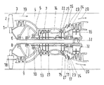
- the gas turbine engine shown comprises a fan 1 with fan blades 2 for generating a core air flow 18 for the core engine 21 and a fan housing 3 with attached Fanströmungskanal 4, which sheathed the housing 5 of the core engine 21 and in which also generated by the fan blades 2 fan flow air flow 19th flows.
- Fanströmungskanal 4 which sheathed the housing 5 of the core engine 21 and in which also generated by the fan blades 2 fan flow air flow 19th flows.
- Fan 4 passed through the core engine 21 and another part 19 through the fan flow channel 4.
- a low pressure shaft 6 and a surrounding high pressure shaft 7 in a plurality of bearings 8, 9, 10, 11 and 12 are mounted in the flow direction follow the fan 1, a high pressure compressor 13, a combustion chamber 14, a high pressure turbine 15 and a low pressure turbine 16.
- the fan 1 and the low pressure turbine 16 are mounted on the central low pressure shaft 6.
- the high-pressure shaft 7 extends coaxially with the low-pressure shaft 6 and encloses it.
- the two shafts 6 and 7 run in the same direction, as the direction of rotation arrows 22 show.
- a means 17 for discharging at least a part the exiting from the high-pressure turbine 15 air flow 20 is arranged in front of the low-pressure turbine 16.
- the device 17 is formed from closable flaps or valve flaps 23 formed in the housing 5 of the engine, which are formed in air openings 24 leading into the fan flow channel 4, arranged in the housing 1, around at least part of the parts emerging from the high-pressure turbine 15 To divert air flow radially outward and divert into the fan flow channel 4.
- the air openings 24 are formed directly in the outer wall 25 of the housing 1.
- the valve flaps 23 are pivotable about axes 26 which are mounted in the wall 25.
- the valve flaps 23 are of the half-open position shown in the figure in one with the wall 25 flush and the air openings 24 sealingly closing, not shown closed position pivotally.
- Upstream baffles 27 prevent an immediate penetration of the fan flow air flow 19 into the air openings 24.
- the flaps 23 may be formed 15 and 16 movable even with open air openings 24 directly into the air flow 20 between the high-pressure and low-pressure turbine.
Landscapes
- Engineering & Computer Science (AREA)
- Chemical & Material Sciences (AREA)
- Combustion & Propulsion (AREA)
- Mechanical Engineering (AREA)
- General Engineering & Computer Science (AREA)
- Physics & Mathematics (AREA)
- Fluid Mechanics (AREA)
- Structures Of Non-Positive Displacement Pumps (AREA)
Abstract
Description
- Die Erfindung bezieht sich auf ein Gasturbinentriebwerk, insbesondere Flugtriebwerk, mit einem Fan, mit einem Fangehäuse und mit einem Fanströmungskanal, sowie mit in Strömungsrichtung im Gehäuse des Triebwerkes hintereinander angeordneten Hochdruck- und Niederdruck-Turbinen.
- Ein Gasturbinentriebwerk, insbesondere Flugtriebwerk, der eingangs genannten Art ist aus der
DE102005006415 A1 vorbekannt. Bei diesem Triebwerk wird die Antriebsleistung zum Betrieb der angeschlossenen Nebenaggregate einer Welle des Triebwerks entnommen. Dies kann die Niederdruckwelle, aber auch die Hochdruckwelle sein, so dass die Antriebsleitung für die Nebenaggregate vom Hochdruck-System des Triebwerkes erzeugt wird. Beim Anlassen des Triebwerkes wird die Richtung der Antriebsleistung umgekehrt und das Hochdruck-System wird auf die erforderliche Startgeschwindigkeit beschleunigt. - Zur Erzeugung größerer elektrischer Leistungen bzw. Energien muss der Leistungsabzug vom Hochdruck-System erheblich gesteigert werden. Der erhöhte Leistungsabzug beeinflusst die Funktionsfähigkeit des Triebwerkes am Boden und im Sinkflug bei Leerlaufbedingungen. Dieser zusätzliche Leistungsabzug vermindert die Schubleistung des Hochdruck-Systems und erfordert, dass die Arbeitslinie des Triebwerkes erhöht wird. Dies wird durch eine Erhöhung der Geschwindigkeit des Triebwerkes erreicht. Die Erhöhung der Geschwindigkeit des Triebwerkes erhöht auch die Geschwindigkeit des Niederdruck-Systems mit dem Ergebnis einer kombinierten Erhöhung der Schubkraft.
- Die erhöhte Schubkraft bei Leerlaufbedingungen am Boden und im Sinkflug hat die Nachteile, dass die minimalen Erfordernisse bei der Geschwindigkeit am Boden und beim Bremsen erhöht werden müssen, und ferner, dass die Dauer des Sinkfluges des Flugzeuges mit höherem Treibstoffverbrauch und verlängerter Sinkflugphase ausgedehnt wird.
- Der Erfindung liegt die Aufgabe zugrunde, ein Gasturbinentriebwerk der gattungsgemäßen Art so auszubilden, dass die angeschlossenen Nebenaggregate mit geringerer Erhöhung der Leistung des Triebwerkes angetrieben werden können.
- Zur Lösung dieser Aufgabe sieht die Erfindung vor, dass in Strömungsrichtung der aus der Hochdruck-Turbine austretenden Luftströmung und hinter der Hochdruck-Turbine eine Einrichtung zur Ableitung mindestens eines Teils der aus der Hochdruck-Turbine ausströmenden Luftströmung vor der Niederdruck-Turbine in radialer Richtung in den Fanströmungskanal vorgesehen ist.
- Der Grundgedanke der Erfindung besteht in der Einführung eines Systems, mit dem die Abluftströmung zwischen dem Hochdruck- und dem Niederdruck-Kompressor während der entsprechenden Leerlaufbedingungen in den Fanströmungskanal bzw. den Fan-Luftstrom abgeleitet wird.
- Gemäß einem weiteren wesentlichen Merkmal der Erfindung ist die Einrichtung zur Ableitung der Luftströmung zwischen der Hochdruck- und der Niederdruck-Turbine aus im Gehäuse des Triebwerkes ausgebildeten, mit Klappen verschließbaren und in den Fanströmungskanal führenden Luftöffnungen gebildet, um mindestens einen Teil der Hochdruck-Turbine austretenden Luftströmung radial abzuleiten und in den Fanströmungskanal einzuleiten. Die KlappenVentile werden geöffnet, wenn sowohl die Geschwindigkeit als auch das minimale Schubkraftniveau erreicht sind.
- Gemäß der Erfindung werden somit zwischen der Hochdruck-Turbine und der Niederdruck-Turbine Klappenventile in das Triebwerksgehäuse eingebaut, um mindestens einen Teil der Luftströmung abzuleiten bzw. der Luft abzulassen und um damit zu vermeiden, dass die gesamte Luft noch über die Niederdruck-Turbine strömt und in dieser Leistung erzeugt. Wenn die Niederdruck-Turbine weniger Luft erhält und damit weniger bzw. keine Leistung erzeugt, wird auch die Drehgeschwindigkeit des Fans geringer oder dieser sogar nicht betrieben. Ein Nebeneffekt ist eine Abbremsung der durch den Fanströmungskanal strömenden Luft.
- Die Erfindung bedeutet die Einführung eines Systems, bei dem das Ablassen mindestens eines Teils der Zwischenstufen-Turbinenluft das Luftvolumen vermindert, das durch die Niederdruck-Turbine expandiert wird, und vermeidet eine Erhöhung der Geschwindigkeit und der Schubkraft der Niederdruck-Turbine, wenn das Hochdruck-System beschleunigt wird, um die mechanischen Leistungsanforderungen zu erfüllen.
- Das Ablassen mindestens eines Teils der Luft aus der Hochdruck-Turbine in den Fanströmungskanal bewirkt außerdem eine Blockierung der durch den Fanströmungskanal strömenden Luft und vermindert damit den durch den Fanströmungskanal strömenden Luftstrom. Es ist erforderlich, eine minimale Geschwindigkeit des Fans aufrechtzuerhalten, um einen angemessenen Luftstrom im Fanströmungskanal zu erreichen, um diesen mit dem heißen Luftstrom im Zwischen-Turbinen-Ablass zu mischen und um eine Überhitzung der Bauteile im Fanströmungskanal zu vermeiden.
- Der erhöhte Druckabfall an der Hochdruck-Turbine kann auch in einer Erhöhung der Triebwerks-Leistung resultieren, vermindert die erforderliche Geschwindigkeit, die das Hochdruck-System benötigt, um betrieben zu werden, wenn die erhöhte mechanische Leistung abgefordert wird, was folglich den Treibstoffverbrauch reduziert.
- Mit diesem System, das eine zunehmende Verminderung der hinter der Hochdruck-Turbine abgelassenen Luft ermöglicht, kann die Geschwindigkeit des Triebwerkes unverändert gehalten werden, während die Flugzeuggeschwindigkeit während der Fahrt am Boden und das Sinkverhältnis beim Landeanflug verändert werden, um den Anforderungen durch eine Variation des Volumens der abgelassenen Luft nachzukommen.
- Ein Ausführungsbeispiel des Gasturbinentriebwerkes, insbesondere Flugtriebwerk, gemäß der Erfindung wird anhand der einzigen Figur näher erläutert. Diese zeigt einen schematischen Längsschnitt durch das Gasturbinentriebwerk.
- Das dargestellte Gasturbinentriebwerk umfasst einen Fan 1 mit Fanschaufeln 2 zur Erzeugung eines Kernluftstromes 18 für das Kerntriebwerk 21 und ein Fangehäuse 3 mit angeschlossenem Fanströmungskanal 4, der das Gehäuse 5 des Kerntriebwerkes 21 ummantelt und in dem ein ebenfalls von den Fanschaufeln 2 erzeugter Fanströmungs-Luftstrom 19 fließt. Damit werden ein Teil 18 der angesaugten Luft vom Fan 4 durch das Kerntriebwerk 21 und ein anderer Teil 19 durch den Fanströmungskanal 4 geleitet. Im Gehäuse 5 des Kerntriebwerkes 21 sind eine Niederdruckwelle 6 und eine diese umgebende Hochdruckwelle 7 in mehreren Lagern 8, 9, 10, 11 und 12 gelagert. In Strömungsrichtung folgen dem Fan 1 ein Hochdruck-Kompressor 13, eine Brennkammer 14, eine Hochdruck-Turbine 15 und eine Niederdruck-Turbine 16. Der Fan 1 und die Niederdruck-Turbine 16 sind auf der zentralen Niederdruckwelle 6 gelagert. Die Hochdruckwelle 7 verläuft co-axial zur Niederdruckwelle 6 und umschließt diese. Die beiden Wellen 6 bzw. 7 laufen gleichsinnig, wie es die Drehrichtungspfeile 22 zeigen.
- In Strömungsrichtung ist hinter der Hochdruck-Turbine 15 und vor der Niederdruck-Turbine 16 und zwischen diesen beiden Turbinen 15, 16 bzw. zwischen dem dritten Lager 11 und dem vierten Lager 12 im Gehäuse 5 des Triebwerkes 21 eine Einrichtung 17 zur Ableitung mindestens eines Teils der aus der Hochdruck-Turbine 15 austretenden Luftströmung 20 vor der Niederdruck-Turbine 16 angeordnet. Die Einrichtung 17 ist aus im Gehäuse 5 des Triebwerkes ausgebildeten, verschließbaren Klappen bzw. Ventilklappen 23 gebildet, die in, in den Fanströmungskanal 4 führenden, im Gehäuse 1 angeordneten Luftöffnungen 24 gebildet sind, um mindestens einen Teil der aus der Hochdruck-Turbine 15 austretenden Luftströmung radial nach außen abzuleiten und in den Fanströmungskanal 4 umzuleiten.
- Wie es die einzige Figur prinzipiell zeigt, sind die Luftöffnungen 24 unmittelbar in der äußeren Wandung 25 des Gehäuses 1 ausgebildet. Die Ventilklappen 23 sind um Achsen 26 schwenkbar, die in der Wandung 25 gelagert sind. Die Ventilklappen 23 sind aus der in der Figur gezeigten halb geöffneten Stellung in eine mit der Wandung 25 bündige und die Luftöffnungen 24 dichtend abschließende, nicht gezeigte Schließstellung schwenkbar. Vorgelagerte Leitbleche 27 verhindern ein unmittelbares Eindringen der Fanströmungs-Luftströmung 19 in die Luftöffnungen 24.
- In einer nicht dargestellten alternativen Ausführungsform können die Klappen 23 auch bei geöffneten Luftöffnungen 24 unmittelbar in die Luftströmung 20 zwischen Hochdruck- und Niederdruck-Turbine 15 bzw. 16 bewegbar ausgebildet sein.
-
- 1
- Fan
- 2
- Fanschaufel
- 3
- Fangehäuse
- 4
- Fanströmungskanal
- 5
- Triebwerks-Gehäuse
- 6
- Niederdruckwelle
- 7
- Hochdruckwelle
- 8- 12
- Lager
- 13
- Hochdruck-Kompressor
- 14
- Brennkammer
- 15
- Hochdruck-Turbine
- 16
- Niederdruck-Turbine
- 17
- Einrichtung zur Ableitung
- 18
- Kernluftstrom
- 19
- Fanströmungs-Luftstrom
- 20
- Luftströmung
- 21
- Kerntriebwerk
- 22
- Drehrichtungspfeil
- 23
- Ventilklappe
- 24
- Luftöffnung
- 25
- Wandung
- 26
- Achse
- 27
- Leitblech
Claims (7)
- Gasturbinentriebwerk, insbesondere Flugtriebwerk, mit einer Fan, mit einem Fangehäuse und mit einem Fanströmungskanal, sowie mit im Gehäuse des Triebwerkes in Strömungsrichtung hintereinander angeordneten Hochdruck- und Niederdruck-Turbinen,
dadurch gekennzeichnet,
dass in Strömungsrichtung der aus der Hochdruck-Turbine (15) austretenden Luftströmung (20) eine Einrichtung (17) zur Ableitung mindestens eines Teils der aus der Hochdruck-Turbine (15) austretenden Luftströmung (20) vor der Niederdruck-Turbine (16) in radialer Richtung in den Fanströmungskanal (4) vorgesehen ist. - Gasturbinentriebwerk nach Anspruch 1, dadurch gekennzeichnet, dass die Einrichtung (17) zur Ableitung der Luftströmung (20) zwischen der Hochdruck-Turbine (15) und der Niederdruck-Turbine (16) aus mit Klappen (23) verschließbaren, in den Fanströmungskanal (4) führenden Luftöffnungen (24) gebildet ist, um die aus der Hochdruck-Turbine (15) austretende Luftströmung (20) radial nach außen abzuleiten und in den Fanströmungskanal (4) einzuleiten.
- Gasturbinentriebwerk nach Anspruch 2, dadurch gekennzeichnet, dass die Klappen (23) bei geöffneten Luftöffnungen (24) unmittelbar in die Luftströmung (20) zwischen Hochdruck- und Niederdruck-Turbine (15, 16) bewegbar sind.
- Gasturbinentriebwerk nach Anspruch 2, dadurch gekennzeichnet, dass die Luftöffnungen (24) unmittelbar in der äußeren Wandung (25) des Gehäuses (1) ausgebildet sind.
- Gasturbinentriebwerk nach Anspruch 4, dadurch gekennzeichnet, dass die Klappen bzw. Ventilklappen (23) um Achsen (26) schwenkbar sind, die in der Wandung (25) gelagert sind.
- Gasturbinentriebwerk nach Anspruch 5, dadurch gekennzeichnet, dass die Ventilklappen (23) aus ihrer Offenstellung in eine mit der Wandung (25) bündige und die Luftöffnungen (24) im Gehäuse (1) dichtend abschließende Schließstellung schwenkbar sind.
- Gasturbinentriebwerk nach einem der Ansprüche 2 bis 6, dadurch gekennzeichnet, dass den Luftöffnungen (24) in Strömungsrichtung der Fanströmungs-Luftströmung (19) im Fanströmungskanal (4) vorgelagerte, auf der Wandung (25) des Gehäuses (1) angeordnete Leitbleche (27) zur Abschirmung der Luftöffnungen (24) zugeordnet sind.
Applications Claiming Priority (1)
| Application Number | Priority Date | Filing Date | Title |
|---|---|---|---|
| DE102008024022A DE102008024022A1 (de) | 2008-05-16 | 2008-05-16 | Gasturbinentriebwerk, insbesondere Flugtriebwerk |
Publications (2)
| Publication Number | Publication Date |
|---|---|
| EP2119900A2 true EP2119900A2 (de) | 2009-11-18 |
| EP2119900A3 EP2119900A3 (de) | 2012-09-05 |
Family
ID=40897446
Family Applications (1)
| Application Number | Title | Priority Date | Filing Date |
|---|---|---|---|
| EP09158579A Withdrawn EP2119900A3 (de) | 2008-05-16 | 2009-04-23 | Gasturbinentriebwerk mit einer Vorrichtung zur Ableitung von Turbinenluft in den Fanströmungskanal |
Country Status (3)
| Country | Link |
|---|---|
| US (1) | US8336288B2 (de) |
| EP (1) | EP2119900A3 (de) |
| DE (1) | DE102008024022A1 (de) |
Families Citing this family (16)
| Publication number | Priority date | Publication date | Assignee | Title |
|---|---|---|---|---|
| FR2904663B1 (fr) * | 2006-08-01 | 2012-02-03 | Snecma | Turbomachine a double flux a variation artificielle de sa section de col |
| US10378439B2 (en) * | 2011-12-30 | 2019-08-13 | Rolls-Royce North American Technologies Inc. | Gas turbine engine with variable speed turbines |
| US8869508B2 (en) * | 2012-01-31 | 2014-10-28 | United Technologies Corporation | Gas turbine engine variable area fan nozzle control |
| US20130192198A1 (en) | 2012-01-31 | 2013-08-01 | Lisa I. Brilliant | Compressor flowpath |
| US9759133B2 (en) * | 2013-03-07 | 2017-09-12 | Rolls-Royce Corporation | Turbofan with variable bypass flow |
| US10087886B2 (en) * | 2014-05-22 | 2018-10-02 | United Technologies Corporation | Turbofan thrust reverser system |
| GB201414071D0 (en) * | 2014-08-08 | 2014-09-24 | Rolls Royce Plc | Gas turbine engine |
| US9951721B2 (en) * | 2014-10-21 | 2018-04-24 | United Technologies Corporation | Three-stream gas turbine engine architecture |
| FR3049652B1 (fr) * | 2016-03-31 | 2020-03-06 | Safran Aircraft Engines | Turbomachine d'aeronef a dispositif de decharge |
| US10221773B2 (en) | 2016-10-07 | 2019-03-05 | General Electric Company | Bleed valve assembly for a gas turbine engine |
| US10233845B2 (en) | 2016-10-07 | 2019-03-19 | General Electric Company | Bleed valve assembly for a gas turbine engine |
| RU2644660C1 (ru) * | 2017-03-07 | 2018-02-13 | Акционерное общество "ОДК-Авиадвигатель" | Газотурбинный двигатель |
| CN107091162B (zh) * | 2017-05-08 | 2019-12-20 | 中国航发湖南动力机械研究所 | 动力涡轮可调式发动机 |
| FR3107318B1 (fr) | 2020-02-17 | 2022-01-14 | Safran Aircraft Engines | Turbomachine d’aéronef à double flux équipée d’un dispositif d’arrêt en survitesse du rotor |
| US20260015968A1 (en) * | 2024-07-15 | 2026-01-15 | Rtx Corporation | Open rotor with aerodynamically isolatable free turbine |
| US12565328B2 (en) | 2024-07-15 | 2026-03-03 | Rtx Corporation | Differential driven open rotor with brake |
Citations (1)
| Publication number | Priority date | Publication date | Assignee | Title |
|---|---|---|---|---|
| DE102005006415A1 (de) | 2005-02-12 | 2006-08-24 | Mtu Aero Engines Gmbh | Gasturbinentriebwerk |
Family Cites Families (16)
| Publication number | Priority date | Publication date | Assignee | Title |
|---|---|---|---|---|
| US2529973A (en) * | 1946-05-29 | 1950-11-14 | Rateau Soc | Arrangement for the starting of two shaft gas turbine propelling means chiefly on board of aircraft |
| US2650666A (en) * | 1946-07-25 | 1953-09-01 | Dorand Rene | Rotary-wing aircraft with jet-driven rotor |
| GB1108454A (en) | 1966-07-12 | 1968-04-03 | Rolls Royce | Improvements in or relating to gas turbine engines |
| US3472487A (en) * | 1967-10-06 | 1969-10-14 | Avco Corp | Wide speed range gas power converter |
| US3508403A (en) | 1968-03-28 | 1970-04-28 | Gen Electric | Turbofan engines |
| DE2328460A1 (de) * | 1973-06-05 | 1975-01-02 | Motoren Turbinen Union | Turbinenstrahltriebwerk in mehrstromund mehrwellen-bauweise |
| GB1484898A (en) * | 1974-09-11 | 1977-09-08 | Rolls Royce | Ducted fan gas turbine engine |
| US4294068A (en) * | 1978-03-27 | 1981-10-13 | The Boeing Company | Supersonic jet engine and method of operating the same |
| GB2158879B (en) | 1984-05-19 | 1987-09-03 | Rolls Royce | Preventing surge in an axial flow compressor |
| FR2640685B1 (fr) * | 1988-12-15 | 1991-02-08 | Snecma | Vanne de decharge de compresseur de turboreacteur |
| US5117628A (en) * | 1990-01-25 | 1992-06-02 | General Electric Company | Mixed flow augmentor pre-mixer |
| US5163286A (en) * | 1991-02-25 | 1992-11-17 | Allied-Signal Inc. | Gas turbine engine with free turbine inlet flow control |
| US5485717A (en) * | 1994-06-29 | 1996-01-23 | Williams International Corporation | Multi-spool by-pass turbofan engine |
| CA2133793A1 (en) * | 1994-10-06 | 1996-04-07 | William E. Carscallen | Inter compressor duct variable geometry annular diffuser/bleed valve |
| US6647708B2 (en) * | 2002-03-05 | 2003-11-18 | Williams International Co., L.L.C. | Multi-spool by-pass turbofan engine |
| WO2006091138A1 (en) * | 2005-02-25 | 2006-08-31 | Volvo Aero Corporation | A bleed structure for a bleed passage in a gas turbine engine |
-
2008
- 2008-05-16 DE DE102008024022A patent/DE102008024022A1/de not_active Withdrawn
-
2009
- 2009-04-23 EP EP09158579A patent/EP2119900A3/de not_active Withdrawn
- 2009-05-15 US US12/453,622 patent/US8336288B2/en not_active Expired - Fee Related
Patent Citations (1)
| Publication number | Priority date | Publication date | Assignee | Title |
|---|---|---|---|---|
| DE102005006415A1 (de) | 2005-02-12 | 2006-08-24 | Mtu Aero Engines Gmbh | Gasturbinentriebwerk |
Also Published As
| Publication number | Publication date |
|---|---|
| US8336288B2 (en) | 2012-12-25 |
| DE102008024022A1 (de) | 2009-11-19 |
| US20090293449A1 (en) | 2009-12-03 |
| EP2119900A3 (de) | 2012-09-05 |
Similar Documents
| Publication | Publication Date | Title |
|---|---|---|
| EP2119900A2 (de) | Gasturbinentriebwerk mit einer Vorrichtung zur Ableitung von Turbinenluft in den Fanströmungskanal | |
| EP2136052B1 (de) | Turboproptriebwerk mit einer Vorrichtung zum Erzeugen eines Kühlluftstroms | |
| DE60133629T2 (de) | Verfahren zum betrieb einer gasturbine mit verstellbaren leitschaufeln | |
| DE2626406C2 (de) | Gasturbinentriebwerk mit variablem Zyklus | |
| DE2813667C2 (de) | ||
| EP2223856B1 (de) | Turboproantrieb mit Druckpropeller | |
| DE60221558T2 (de) | Turbinenmotor mit luftgekühlter turbine | |
| DE19824766C2 (de) | Gasturbine sowie Verfahren zur Kühlung einer Turbinenstufe | |
| DE4106752A1 (de) | Vorrichtung zum liefern von abzapfluft aus einem flugzeuggasturbinentriebwerk | |
| DE60023681T2 (de) | Kühlung der hochdruckturbinenstufe einer gasturbine | |
| DE69936939T2 (de) | Zapfsystem für eine kompressorwand sowie betriebsverfahren | |
| DE2626405A1 (de) | Gasturbinentriebwerk mit geteiltem geblaese | |
| DE1626130A1 (de) | Gasturbinentriebwerksanlage | |
| DE2042478A1 (de) | Gasturbinenstrahltriebwerk für Flugzeuge mit Einrichtungen zur Bauteilkühlung und Verdichterregelung | |
| DE2121069A1 (de) | Gasturbinentriebwerk mit Kuhlsystem | |
| DE112012002692B4 (de) | Vorrichtung und Verfahren zur Reduzierung des Luftmassenflusses zur emissionsarmen Verbrennung über einen erweiterten Bereich in einwelligen Gasturbinen | |
| DE2147537A1 (de) | Kühleinrichtung für die Enden von Turbinenlaufschaufeln mit Luftexpansion | |
| EP3537006A1 (de) | Planetengetriebe und flugtriebwerk mit einem planetengetriebe | |
| DE2454054A1 (de) | Innentriebwerk bzw. gasgenerator fuer gasturbinentriebwerke | |
| DE60221403T2 (de) | Doppelstrom - verdichter | |
| WO2008017567A1 (de) | Lufteinlass eines strahltriebwerks | |
| WO2008092427A1 (de) | Gasturbine mit einem nachleitkranz und mit einem mischer | |
| DE2853340A1 (de) | Vorrichtung zum erzeugen eines vorwirbels am verdichtereingang eines turbinen-triebwerkes | |
| DE60317118T2 (de) | In eine Maschine intigrierte Hilfsenergieeinheit | |
| DE102018113753A1 (de) | Planetengetriebe und Gasturbinentriebwerk |
Legal Events
| Date | Code | Title | Description |
|---|---|---|---|
| PUAI | Public reference made under article 153(3) epc to a published international application that has entered the european phase |
Free format text: ORIGINAL CODE: 0009012 |
|
| AK | Designated contracting states |
Kind code of ref document: A2 Designated state(s): AT BE BG CH CY CZ DE DK EE ES FI FR GB GR HR HU IE IS IT LI LT LU LV MC MK MT NL NO PL PT RO SE SI SK TR |
|
| PUAL | Search report despatched |
Free format text: ORIGINAL CODE: 0009013 |
|
| AK | Designated contracting states |
Kind code of ref document: A3 Designated state(s): AT BE BG CH CY CZ DE DK EE ES FI FR GB GR HR HU IE IS IT LI LT LU LV MC MK MT NL NO PL PT RO SE SI SK TR |
|
| RIC1 | Information provided on ipc code assigned before grant |
Ipc: F02K 3/075 20060101AFI20120731BHEP Ipc: F02C 9/18 20060101ALI20120731BHEP |
|
| STAA | Information on the status of an ep patent application or granted ep patent |
Free format text: STATUS: THE APPLICATION IS DEEMED TO BE WITHDRAWN |
|
| 18D | Application deemed to be withdrawn |
Effective date: 20130306 |