EP2119876A2 - Support de palier pour une turbine à gaz pendant excentrage - Google Patents
Support de palier pour une turbine à gaz pendant excentrage Download PDFInfo
- Publication number
- EP2119876A2 EP2119876A2 EP09159485A EP09159485A EP2119876A2 EP 2119876 A2 EP2119876 A2 EP 2119876A2 EP 09159485 A EP09159485 A EP 09159485A EP 09159485 A EP09159485 A EP 09159485A EP 2119876 A2 EP2119876 A2 EP 2119876A2
- Authority
- EP
- European Patent Office
- Prior art keywords
- rotor shaft
- assembly
- rotor
- shaft
- race
- Prior art date
- Legal status (The legal status is an assumption and is not a legal conclusion. Google has not performed a legal analysis and makes no representation as to the accuracy of the status listed.)
- Withdrawn
Links
Images
Classifications
-
- F—MECHANICAL ENGINEERING; LIGHTING; HEATING; WEAPONS; BLASTING
- F01—MACHINES OR ENGINES IN GENERAL; ENGINE PLANTS IN GENERAL; STEAM ENGINES
- F01D—NON-POSITIVE DISPLACEMENT MACHINES OR ENGINES, e.g. STEAM TURBINES
- F01D21/00—Shutting-down of machines or engines, e.g. in emergency; Regulating, controlling, or safety means not otherwise provided for
- F01D21/04—Shutting-down of machines or engines, e.g. in emergency; Regulating, controlling, or safety means not otherwise provided for responsive to undesired position of rotor relative to stator or to breaking-off of a part of the rotor, e.g. indicating such position
- F01D21/045—Shutting-down of machines or engines, e.g. in emergency; Regulating, controlling, or safety means not otherwise provided for responsive to undesired position of rotor relative to stator or to breaking-off of a part of the rotor, e.g. indicating such position special arrangements in stators or in rotors dealing with breaking-off of part of rotor
-
- F—MECHANICAL ENGINEERING; LIGHTING; HEATING; WEAPONS; BLASTING
- F01—MACHINES OR ENGINES IN GENERAL; ENGINE PLANTS IN GENERAL; STEAM ENGINES
- F01D—NON-POSITIVE DISPLACEMENT MACHINES OR ENGINES, e.g. STEAM TURBINES
- F01D25/00—Component parts, details, or accessories, not provided for in, or of interest apart from, other groups
- F01D25/16—Arrangement of bearings; Supporting or mounting bearings in casings
- F01D25/162—Bearing supports
-
- F—MECHANICAL ENGINEERING; LIGHTING; HEATING; WEAPONS; BLASTING
- F05—INDEXING SCHEMES RELATING TO ENGINES OR PUMPS IN VARIOUS SUBCLASSES OF CLASSES F01-F04
- F05D—INDEXING SCHEME FOR ASPECTS RELATING TO NON-POSITIVE-DISPLACEMENT MACHINES OR ENGINES, GAS-TURBINES OR JET-PROPULSION PLANTS
- F05D2260/00—Function
- F05D2260/70—Adjusting of angle of incidence or attack of rotating blades
- F05D2260/79—Bearing, support or actuation arrangements therefor
-
- F—MECHANICAL ENGINEERING; LIGHTING; HEATING; WEAPONS; BLASTING
- F05—INDEXING SCHEMES RELATING TO ENGINES OR PUMPS IN VARIOUS SUBCLASSES OF CLASSES F01-F04
- F05D—INDEXING SCHEME FOR ASPECTS RELATING TO NON-POSITIVE-DISPLACEMENT MACHINES OR ENGINES, GAS-TURBINES OR JET-PROPULSION PLANTS
- F05D2260/00—Function
- F05D2260/94—Functionality given by mechanical stress related aspects such as low cycle fatigue [LCF] of high cycle fatigue [HCF]
- F05D2260/941—Functionality given by mechanical stress related aspects such as low cycle fatigue [LCF] of high cycle fatigue [HCF] particularly aimed at mechanical or thermal stress reduction
-
- F—MECHANICAL ENGINEERING; LIGHTING; HEATING; WEAPONS; BLASTING
- F16—ENGINEERING ELEMENTS AND UNITS; GENERAL MEASURES FOR PRODUCING AND MAINTAINING EFFECTIVE FUNCTIONING OF MACHINES OR INSTALLATIONS; THERMAL INSULATION IN GENERAL
- F16C—SHAFTS; FLEXIBLE SHAFTS; ELEMENTS OR CRANKSHAFT MECHANISMS; ROTARY BODIES OTHER THAN GEARING ELEMENTS; BEARINGS
- F16C19/00—Bearings with rolling contact, for exclusively rotary movement
- F16C19/52—Bearings with rolling contact, for exclusively rotary movement with devices affected by abnormal or undesired conditions
- F16C19/522—Bearings with rolling contact, for exclusively rotary movement with devices affected by abnormal or undesired conditions related to load on the bearing, e.g. bearings with load sensors or means to protect the bearing against overload
-
- F—MECHANICAL ENGINEERING; LIGHTING; HEATING; WEAPONS; BLASTING
- F16—ENGINEERING ELEMENTS AND UNITS; GENERAL MEASURES FOR PRODUCING AND MAINTAINING EFFECTIVE FUNCTIONING OF MACHINES OR INSTALLATIONS; THERMAL INSULATION IN GENERAL
- F16C—SHAFTS; FLEXIBLE SHAFTS; ELEMENTS OR CRANKSHAFT MECHANISMS; ROTARY BODIES OTHER THAN GEARING ELEMENTS; BEARINGS
- F16C2360/00—Engines or pumps
- F16C2360/23—Gas turbine engines
Definitions
- This application relates generally to gas turbine engine rotor assemblies and, more particularly, to load reduction assemblies for gas turbine engine rotor assemblies.
- Gas turbine engines typically include a rotor assembly, a compressor, and a turbine.
- the rotor assembly includes a fan that includes an array of fan blades extending radially outward from a rotor shaft.
- the rotor shaft transfers power and rotary motion from the turbine to the compressor and the fan and is supported longitudinally with a plurality of bearing assemblies. Additionally, the rotor assembly has an axis of rotation that passes through a rotor assembly center of gravity.
- Known bearing assemblies include rolling elements and a paired race, wherein the rolling elements are supported within the paired race.
- the rotor assembly is typically supported on three bearing assemblies, one of which is a thrust bearing assembly and two which are roller bearing assemblies.
- the thrust bearing assembly supports the rotor shaft and minimizes axial and radial movement of the rotor shaft assembly.
- the remaining roller bearing assemblies support radial movement of the rotor shaft.
- a fragment of a fan blade may become separated from the remainder of the blade. Accordingly, a substantial rotary unbalance load may be created within the damaged fan and carried substantially by the fan shaft bearings, the fan bearing supports, and the fan support frames.
- known engines include support components for the fan rotor support system that are sized to provide additional strength for the fan support system.
- increasing the strength of the support components undesirably increases an overall weight of the engine and decreases an overall efficiency of the engine when the engine is operated without substantial rotor imbalances.
- LRD load reduction device
- the pitching fan rotor After the primary fuse fails, the pitching fan rotor often induces a large moment to a next closest bearing.
- the next closest bearing is known as the number two bearing position.
- the moment induced to the number two bearing induces high bending and stress loads to the fan rotor locally.
- the radial and pitching rotation stiffness of the number two bearing position are often softened or released to maintain a safe shutdown and subsequent windmill of the engine during the time it takes to land an aircraft.
- the forces are still large enough that withstanding these loads with acceptable stresses adds weight and cost to the engine/aircraft system.
- a method for reducing dynamic loading of a gas turbine engine includes a rotor shaft assembly including a rotor shaft, a bearing assembly, a mounting race, and a support frame, the mounting race including a spherical surface.
- the method includes supporting the rotor shaft on the gas turbine engine support frame with the bearing assembly, the rotor shaft including a yield portion configured to permit yielding of the rotor shaft during an imbalance operation.
- rotor assembly for a gas turbine engine includes a rotor shaft comprising a recess and a yield portion defined between said recess and a forward bearing seat, a mounting race comprising an upstream side, a downstream side, and a spherical surface extending therebetween, a bearing assembly coupled to the mounting race to support the rotor shaft on a support frame, and a mechanical fuse coupled to said mounting race to secure said bearing assembly.
- the mechanical fuse is configured to fail during an imbalance condition of the rotor shaft, such failure causing the rotor shaft to operate above a vibratory bending mode frequency of the rotor shaft.
- a gas turbine engine assembly includes a rotor assembly for a fan wherein the rotor assembly includes a bearing assembly coupled to a support frame, a cone shaft coupled to the bearing assembly, and a rotor shaft comprising a yield portion coupled to said cone shaft through a mounting race.
- the mounting race includes an upstream side, a downstream side, and a spherical surface extending therebetween.
- the yield portion is configured to reduce an imbalance in the rotor shaft by yielding in response to torsional and moment loads generated in the rotor shaft.
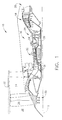
- FIG. 1 is a schematic illustration of an exemplary engine assembly 10 having a longitudinal axis 12.
- Engine assembly 10 includes a fan assembly 14, a core gas turbine engine 16 that is disposed downstream from fan assembly 14, and a low-pressure turbine 18 that is disposed downstream from core gas turbine engine 16.
- Core gas turbine engine 16 includes a high-pressure compressor 22, a combustor 24, and a high-pressure turbine 26.
- Fan assembly 14 includes a plurality of fan blades 28 that extend radially outward from a rotor disk 30 of a rotor 31, and a fan casing 32 that extends circumferentially about fan blades 28.
- Engine assembly 10 has an intake side 36 and an exhaust side 38.
- Compressor 22 and high-pressure turbine 26 are coupled together by a second drive shaft 39.
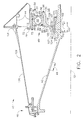
- FIG 2 is a cross-sectional view of a rotor and bearing assembly 40 that may be used with a gas turbine engine, such as engine assembly 10 shown in Figure 1 .
- the gas turbine engine is a GEnx engine available from General Electric Company, Cincinnati, Ohio.
- Rotor and bearing assembly 40 includes rotor disk 30 (shown in Figure 1 ) and a rotor shaft 42 which supports an array of fan blades 28 (shown in Figure 1 ) that extend radially outward from rotor disk 30.
- Rotor shaft 42 is rotatably secured to a structural support frame 44 with longitudinally spaced bearing assemblies 46 and 48 that support rotor shaft 42 on support frame 44.
- bearing assembly 48 is located in a number two bearing position, aft of number one bearing 46, and is a fan thrust bearing and bearing 46 is supported by a forward bearing support 129 coupled to support frame 44 through a forward bearing support flange 131.
- Rotor shaft 42 includes a yield portion 49 configured to permit rotor shaft 42 to yield due to torsional and moment loads generated in rotor shaft 42 during for example, a bladeout or other imbalance condition.
- Yield portion 49 may include a radially thinner portion of rotor shaft 42 or may include a circumferential material treatment that facilitates permitting rotor shaft 42 to yield at yield portion 49.
- rotor shaft 42 does not include yield portion 49, but rather most, if not all, of rotor shaft 42 is configured to yield when subjected to predetermined torsional and/or moment loads. More specifically, in such an embodiment, shaft 42 may be configured to substantially simultaneously yield in bending, as distributed substantially over a full length of shaft 42, when subjected to predetermined torsional and/or moment load.
- each bearing assembly 48 includes a paired race 50 and a rolling element 52.
- Paired race 50 includes an outer race 54 and an inner race 56 radially inward from outer race 54.
- Rolling element 52 is disposed between inner race 56 and outer race 54.
- Bearing assembly 48 is enclosed within a sealed annular compartment 58 radially bounded by rotor shaft 42 and support frame 44.
- Rolling element 52 may be a plurality of elements including, but not limited to, a ball bearing or a roller bearing.
- Support frame 44 includes a recess 70 defined within a bearing support 72 and sized to receive outer race 54.
- Outer race 54 is secured within bearing support 72 with a spanner nut 73 such that an outer surface 74 of outer race 54 is adjacent an inner surface 76 of bearing support 72.
- outer race 54 is secured within support frame recess 70 with a spanner nut 73.
- a fastener 78 secures bearing support 72 and outer race 54 within recess 70.
- bearing support 72 is radially flexible.
- a face 79 of outer race 54 is contoured and sized to receive rolling element 52 in rollable contact.
- Inner race 56 includes a face 80 and an inner surface 82.
- Inner race face 80 is contoured and sized to receive rolling element 52 in rollable contact.
- Inner race 56 is secured within a recess 84 within a cone shaft 86 such that inner race inner surface 82 is adjacent an outer surface 88 of recess 84.
- inner race 56 is split race mating and rolling element 52 is a ball bearing.
- outer race 54 is split race mating and rolling element 52 is a ball bearing.
- Cone shaft 86 extends radially outward from fan rotor shaft 42 and includes an outer portion 90, an inner portion 92, and a body 94 extending therebetween.
- Recess 84 extends within cone shaft outer portion 90 and is sized to receive inner race 56.
- a bearing spanner nut 96 secures inner race 56 within cone shaft recess 84.
- Body 94 provides axial thrust and radial support to bearing assembly 48.
- Cone shaft inner portion 92 includes an inner surface 98. Inner surface 98 is contoured to fit in slidable contact against a face 100 of a mounting race 102.
- Mounting race 102 reduces static loads to rotor and bearing assembly 40 and dynamic loads to support frame 44.
- Mounting race 102 is secured to fan rotor shaft 42 with a pair of retainers 104 and 105.
- mounting race 102 is secured in position with at least one shear pin (not shown), such as is described in U.S. Pat. No. 6,783,319 .
- retainers 104 and 105 are spring clamps and can provide axial preload to shaft inner portion 92. Accordingly, mounting race 102 rotates simultaneously with rotor shaft 42.
- Fan rotor shaft 42 includes a recess 110 sized to receive mounting race 102 and retainers 104 and 105 such that a gap (not shown) exists between an inner face 114 of retainer 104 and an inner face 116 of retainer 105.
- Mounting race face 100 is a spherical surface. In one embodiment, mounting race face 100 is radially thin and is ovalized elastically to assemble to mounting race 102. In an alternative embodiment, recess 110 is sized to receive mounting race 102 and cone shaft 86 is secured to mounting race 102 using one or more circumferentially spaced mechanical fuses 106 and/or 107.
- mounting race 102 includes a width 120 that is substantially equal to a width 122 of cone shaft inner portion 92 such that when assembled, an upstream side 124 of cone shaft inner portion 92 is substantially coplanar with retainer inner face 114, and a downstream side 126 of cone shaft inner portion 92 is substantially coplanar with retainer inner face 116.
- An axial preload exits to limit rotation of cone shaft inner portion 92 with respect to mounting race 102, when cone shaft inner portion 92 is not mounted substantially co-planer with mounting race 102.
- bearing assembly 48 and mounting race 102 may be pre-assembled on fan rotor shaft 42. Pre-assembling bearing assembly 48 and mounting race 102 to rotor shaft 42 minimizes assembly damage and bearing contamination during main engine assembly. Furthermore, as mounting race 102 is secured to fan rotor shaft 42 with retainers 104 and 105, the gap between respective retainers 104 and 105, and mounting race 102 is eliminated. The gap is sized to permit retainers 104 and 105 to provide a controlled amount of axial preload to mounting race 102. In addition, retainers 104 and 105 maintain mounting race 102 substantially square with relation to shaft 42 during assembly and normal operation.
- an unbalance of engine 10 may cause high radial forces to be applied to fan assembly 14 (shown in Figure 1 ) and a forward most engine bearing.
- the high radial forces may cause a primary fuse portion 128 to fail at an engine number one bearing position.
- the primary fuse failure allows fan assembly 14 to rotate about a new axis of rotation, thus changing a center of gravity of rotor shaft 42 and inducing bending loads on rotor shaft 42 that induce a moment load on bearing assembly 48 at the number two engine bearing position.
- Retainers 104 and 105 are fabricated from a material that fails at a pre-determined moment load applied to rotor shaft 42.
- mounting race spherical face 100 allows shaft 42 to pitch such that a shaft center of rotation (not shown) approaches that of the new rotor center of gravity.
- fuses 106 and 107 are fabricated from a material that fails at a pre-determined moment load applied to rotor shaft 42. After fuses 106 or 107 fail, mounting race spherical face 100 allows shaft 42 to pitch such that a shaft center of rotation (not shown) approaches that of the new rotor center of gravity. Rotor shaft 42 yields at yield portion 49 due to torsional and moment loads.
- the above-described rotor assembly is cost-effective and highly reliable.
- the rotor assembly includes a bearing assembly that fails when a pre-determined moment load is applied to the bearing assembly.
- a bearing assembly fails, bending loads transmitted to the rotor assembly are reduced when the rotor shaft yields at a yield portion towards the imbalance.
- the rotor assembly does not transmit potentially damaging dynamic loads to the structural frame supporting the rotor shaft because the center of rotation approaches the rotor shaft center of gravity.
- the rotor assembly maintains rotational frequency above a fan windmilling frequency.
Landscapes
- Engineering & Computer Science (AREA)
- Mechanical Engineering (AREA)
- General Engineering & Computer Science (AREA)
- Turbine Rotor Nozzle Sealing (AREA)
- Structures Of Non-Positive Displacement Pumps (AREA)
- Rolling Contact Bearings (AREA)
Applications Claiming Priority (1)
| Application Number | Priority Date | Filing Date | Title |
|---|---|---|---|
| US12/122,282 US8167531B2 (en) | 2008-05-16 | 2008-05-16 | Method and apparatus for supporting rotor assemblies during unbalances |
Publications (2)
| Publication Number | Publication Date |
|---|---|
| EP2119876A2 true EP2119876A2 (fr) | 2009-11-18 |
| EP2119876A3 EP2119876A3 (fr) | 2017-06-14 |
Family
ID=40688562
Family Applications (1)
| Application Number | Title | Priority Date | Filing Date |
|---|---|---|---|
| EP09159485.3A Withdrawn EP2119876A3 (fr) | 2008-05-16 | 2009-05-06 | Support de palier pour une turbine à gaz pendant excentrage |
Country Status (2)
| Country | Link |
|---|---|
| US (1) | US8167531B2 (fr) |
| EP (1) | EP2119876A3 (fr) |
Cited By (2)
| Publication number | Priority date | Publication date | Assignee | Title |
|---|---|---|---|---|
| US9037381B2 (en) | 2013-02-19 | 2015-05-19 | Rolls-Royce Plc | Determining the deterioration of a gas turbine engine in use |
| CN108071429A (zh) * | 2016-11-17 | 2018-05-25 | 中国航发商用航空发动机有限责任公司 | 可失效转子支承结构及航空发动机 |
Families Citing this family (20)
| Publication number | Priority date | Publication date | Assignee | Title |
|---|---|---|---|---|
| FR2966208B1 (fr) * | 2010-10-13 | 2012-12-28 | Snecma | Boitier de liaison entre un arbre d'entrainement de soufflante de moteur et un palier de roulement |
| US8747054B2 (en) * | 2011-01-24 | 2014-06-10 | United Technologies Corporation | Bearing system for gas turbine engine |
| US10196934B2 (en) | 2016-02-11 | 2019-02-05 | General Electric Company | Rotor support system with shape memory alloy components for a gas turbine engine |
| US11421551B2 (en) | 2016-05-25 | 2022-08-23 | General Electric Company | Turbine bearing support |
| US10197102B2 (en) | 2016-10-21 | 2019-02-05 | General Electric Company | Load reduction assemblies for a gas turbine engine |
| US10274017B2 (en) | 2016-10-21 | 2019-04-30 | General Electric Company | Method and system for elastic bearing support |
| FR3063310B1 (fr) * | 2017-02-28 | 2019-04-26 | Safran Aircraft Engines | Moteur d'aeronef comprenant un palier entre deux arbres concentriques |
| GB201704045D0 (en) * | 2017-03-14 | 2017-04-26 | Rolls Royce Plc | A seal panel for gas turbine engine |
| FR3066534B1 (fr) * | 2017-05-22 | 2020-01-10 | Safran Aircraft Engines | Ensemble pour turbomachine d'aeronef presentant un systeme de decouplage ameliore en cas de perte d'aube de soufflante |
| US11131244B2 (en) | 2017-11-03 | 2021-09-28 | General Electric Company | Power transmission system and gas turbine engine comprising the same |
| CN107666200B (zh) * | 2017-11-09 | 2024-02-06 | 宜兴市华井科技有限公司 | 一种高效氮化硅脱气转子装置 |
| US11261753B2 (en) | 2017-12-06 | 2022-03-01 | General Electric Company | Method and device for connecting fan rotor to low pressure turbine rotor |
| GB201900382D0 (en) | 2019-01-11 | 2019-02-27 | Rolls Royce Plc | Gas turbine engine |
| US10844746B2 (en) * | 2019-03-29 | 2020-11-24 | Pratt & Whitney Canada Corp. | Bearing housing |
| US11105223B2 (en) | 2019-08-08 | 2021-08-31 | General Electric Company | Shape memory alloy reinforced casing |
| US11420755B2 (en) | 2019-08-08 | 2022-08-23 | General Electric Company | Shape memory alloy isolator for a gas turbine engine |
| US11274557B2 (en) | 2019-11-27 | 2022-03-15 | General Electric Company | Damper assemblies for rotating drum rotors of gas turbine engines |
| US11280219B2 (en) | 2019-11-27 | 2022-03-22 | General Electric Company | Rotor support structures for rotating drum rotors of gas turbine engines |
| US11047306B1 (en) | 2020-02-25 | 2021-06-29 | General Electric Company | Gas turbine engine reverse bleed for coking abatement |
| US11828235B2 (en) | 2020-12-08 | 2023-11-28 | General Electric Company | Gearbox for a gas turbine engine utilizing shape memory alloy dampers |
Citations (1)
| Publication number | Priority date | Publication date | Assignee | Title |
|---|---|---|---|---|
| US6783319B2 (en) | 2001-09-07 | 2004-08-31 | General Electric Co. | Method and apparatus for supporting rotor assemblies during unbalances |
Family Cites Families (16)
| Publication number | Priority date | Publication date | Assignee | Title |
|---|---|---|---|---|
| GB2079402B (en) * | 1980-06-27 | 1984-02-22 | Rolls Royce | System for supporting a rotor in conditions of dynamic imbalance |
| US5433584A (en) * | 1994-05-05 | 1995-07-18 | Pratt & Whitney Canada, Inc. | Bearing support housing |
| US5791789A (en) * | 1997-04-24 | 1998-08-11 | United Technologies Corporation | Rotor support for a turbine engine |
| SE512651C2 (sv) * | 1998-06-25 | 2000-04-17 | Skf Mekanprodukter Ab | Lagerenhet |
| GB9814567D0 (en) * | 1998-07-07 | 1998-09-02 | Rolls Royce Plc | A rotor assembly |
| US6082959A (en) * | 1998-12-22 | 2000-07-04 | United Technologies Corporation | Method and apparatus for supporting a rotatable shaft within a gas turbine engine |
| US6331078B1 (en) * | 1998-12-23 | 2001-12-18 | United Technologies Corporation | Turbine engine bearing |
| US6491497B1 (en) * | 2000-09-22 | 2002-12-10 | General Electric Company | Method and apparatus for supporting rotor assemblies during unbalances |
| US6447248B1 (en) * | 2000-10-20 | 2002-09-10 | General Electric Company | Bearing support fuse |
| US6439772B1 (en) * | 2000-12-01 | 2002-08-27 | General Electric Company | Method and apparatus for supporting rotor assembly bearings |
| US6413046B1 (en) * | 2001-01-26 | 2002-07-02 | General Electric Company | Method and apparatus for centering rotor assembly damper bearings |
| US6443698B1 (en) * | 2001-01-26 | 2002-09-03 | General Electric Company | Method and apparatus for centering rotor assembly damper bearings |
| US6619908B2 (en) * | 2001-09-10 | 2003-09-16 | Pratt & Whitney Canada Corp. | Axial and radial seal arrangement |
| FR2837240B1 (fr) * | 2002-03-14 | 2004-07-09 | Snecma Moteurs | Dispositif de support et de recentrage d'un arbre d'une soufflante d'un turboreacteur apres decouplage |
| FR2869073B1 (fr) * | 2004-04-14 | 2006-07-21 | Snecma Moteurs Sa | Systeme de blocage d'un arbre principal de moteur a palier fusible |
| US7342331B2 (en) * | 2005-10-25 | 2008-03-11 | Honeywell International, Inc. | Multi-plane flexible rotor balancing |
-
2008
- 2008-05-16 US US12/122,282 patent/US8167531B2/en active Active
-
2009
- 2009-05-06 EP EP09159485.3A patent/EP2119876A3/fr not_active Withdrawn
Patent Citations (1)
| Publication number | Priority date | Publication date | Assignee | Title |
|---|---|---|---|---|
| US6783319B2 (en) | 2001-09-07 | 2004-08-31 | General Electric Co. | Method and apparatus for supporting rotor assemblies during unbalances |
Cited By (3)
| Publication number | Priority date | Publication date | Assignee | Title |
|---|---|---|---|---|
| US9037381B2 (en) | 2013-02-19 | 2015-05-19 | Rolls-Royce Plc | Determining the deterioration of a gas turbine engine in use |
| CN108071429A (zh) * | 2016-11-17 | 2018-05-25 | 中国航发商用航空发动机有限责任公司 | 可失效转子支承结构及航空发动机 |
| CN108071429B (zh) * | 2016-11-17 | 2019-11-12 | 中国航发商用航空发动机有限责任公司 | 可失效转子支承结构及航空发动机 |
Also Published As
| Publication number | Publication date |
|---|---|
| US8167531B2 (en) | 2012-05-01 |
| US20090285674A1 (en) | 2009-11-19 |
| EP2119876A3 (fr) | 2017-06-14 |
Similar Documents
| Publication | Publication Date | Title |
|---|---|---|
| US8167531B2 (en) | Method and apparatus for supporting rotor assemblies during unbalances | |
| CA2356766C (fr) | Methode et appareil pour soutenir des assemblages rotors pendant des balourds | |
| CA2934668C (fr) | Dispositif de palier servant a supporter une tige de rotor d'un moteur de turbine a gaz | |
| US6783319B2 (en) | Method and apparatus for supporting rotor assemblies during unbalances | |
| EP3205840B1 (fr) | Système de support de rotor en comprenant composants en alliage à mémoire de forme pour une turbine à gaz | |
| US10197102B2 (en) | Load reduction assemblies for a gas turbine engine | |
| US6540483B2 (en) | Methods and apparatus for bearing outer race axial retention | |
| EP1655457B1 (fr) | Turbine à gaz et procédé pour son montage | |
| US6098399A (en) | Ducted fan gas turbine engine | |
| JP4101496B2 (ja) | ファン連結解除ヒューズ | |
| EP0631041B1 (fr) | Cadre de turbine rotatif | |
| US6082959A (en) | Method and apparatus for supporting a rotatable shaft within a gas turbine engine | |
| US6073439A (en) | Ducted fan gas turbine engine | |
| US7404678B2 (en) | Rotor recentering after decoupling | |
| US6079200A (en) | Ducted fan gas turbine engine with fan shaft frangible connection | |
| US11261753B2 (en) | Method and device for connecting fan rotor to low pressure turbine rotor | |
| EP2546460A2 (fr) | Moteur à turbine et son dispositif de réduction de charge | |
| EP3647541B1 (fr) | Bague de vernier fendue pour ensemble d'empilement de rotor d'une turbine | |
| GB2394015A (en) | Powerplant shaft with vibration damping device |
Legal Events
| Date | Code | Title | Description |
|---|---|---|---|
| PUAI | Public reference made under article 153(3) epc to a published international application that has entered the european phase |
Free format text: ORIGINAL CODE: 0009012 |
|
| AK | Designated contracting states |
Kind code of ref document: A2 Designated state(s): AT BE BG CH CY CZ DE DK EE ES FI FR GB GR HR HU IE IS IT LI LT LU LV MC MK MT NL NO PL PT RO SE SI SK TR |
|
| PUAL | Search report despatched |
Free format text: ORIGINAL CODE: 0009013 |
|
| AK | Designated contracting states |
Kind code of ref document: A3 Designated state(s): AT BE BG CH CY CZ DE DK EE ES FI FR GB GR HR HU IE IS IT LI LT LU LV MC MK MT NL NO PL PT RO SE SI SK TR |
|
| AX | Request for extension of the european patent |
Extension state: AL BA RS |
|
| RIC1 | Information provided on ipc code assigned before grant |
Ipc: F01D 25/16 20060101ALI20170505BHEP Ipc: F01D 21/04 20060101AFI20170505BHEP Ipc: F16C 19/52 20060101ALN20170505BHEP |
|
| STAA | Information on the status of an ep patent application or granted ep patent |
Free format text: STATUS: REQUEST FOR EXAMINATION WAS MADE |
|
| 17P | Request for examination filed |
Effective date: 20171214 |
|
| RBV | Designated contracting states (corrected) |
Designated state(s): AT BE BG CH CY CZ DE DK EE ES FI FR GB GR HR HU IE IS IT LI LT LU LV MC MK MT NL NO PL PT RO SE SI SK TR |
|
| STAA | Information on the status of an ep patent application or granted ep patent |
Free format text: STATUS: EXAMINATION IS IN PROGRESS |
|
| 17Q | First examination report despatched |
Effective date: 20180503 |
|
| RIC1 | Information provided on ipc code assigned before grant |
Ipc: F01D 21/04 20060101AFI20190723BHEP Ipc: F02C 6/12 20060101ALI20190723BHEP Ipc: F01D 25/16 20060101ALI20190723BHEP Ipc: F16C 19/52 20060101ALN20190723BHEP |
|
| STAA | Information on the status of an ep patent application or granted ep patent |
Free format text: STATUS: EXAMINATION IS IN PROGRESS |
|
| STAA | Information on the status of an ep patent application or granted ep patent |
Free format text: STATUS: THE APPLICATION IS DEEMED TO BE WITHDRAWN |
|
| 18D | Application deemed to be withdrawn |
Effective date: 20201201 |