EP0631041B1 - Cadre de turbine rotatif - Google Patents
Cadre de turbine rotatif Download PDFInfo
- Publication number
- EP0631041B1 EP0631041B1 EP94304145A EP94304145A EP0631041B1 EP 0631041 B1 EP0631041 B1 EP 0631041B1 EP 94304145 A EP94304145 A EP 94304145A EP 94304145 A EP94304145 A EP 94304145A EP 0631041 B1 EP0631041 B1 EP 0631041B1
- Authority
- EP
- European Patent Office
- Prior art keywords
- rotor
- struts
- drive shaft
- turbine frame
- band
- Prior art date
- Legal status (The legal status is an assumption and is not a legal conclusion. Google has not performed a legal analysis and makes no representation as to the accuracy of the status listed.)
- Expired - Lifetime
Links
Images

Classifications
-
- F—MECHANICAL ENGINEERING; LIGHTING; HEATING; WEAPONS; BLASTING
- F01—MACHINES OR ENGINES IN GENERAL; ENGINE PLANTS IN GENERAL; STEAM ENGINES
- F01D—NON-POSITIVE DISPLACEMENT MACHINES OR ENGINES, e.g. STEAM TURBINES
- F01D25/00—Component parts, details, or accessories, not provided for in, or of interest apart from, other groups
- F01D25/16—Arrangement of bearings; Supporting or mounting bearings in casings
- F01D25/162—Bearing supports
-
- F—MECHANICAL ENGINEERING; LIGHTING; HEATING; WEAPONS; BLASTING
- F01—MACHINES OR ENGINES IN GENERAL; ENGINE PLANTS IN GENERAL; STEAM ENGINES
- F01D—NON-POSITIVE DISPLACEMENT MACHINES OR ENGINES, e.g. STEAM TURBINES
- F01D5/00—Blades; Blade-carrying members; Heating, heat-insulating, cooling or antivibration means on the blades or the members
- F01D5/02—Blade-carrying members, e.g. rotors
-
- F—MECHANICAL ENGINEERING; LIGHTING; HEATING; WEAPONS; BLASTING
- F02—COMBUSTION ENGINES; HOT-GAS OR COMBUSTION-PRODUCT ENGINE PLANTS
- F02C—GAS-TURBINE PLANTS; AIR INTAKES FOR JET-PROPULSION PLANTS; CONTROLLING FUEL SUPPLY IN AIR-BREATHING JET-PROPULSION PLANTS
- F02C3/00—Gas-turbine plants characterised by the use of combustion products as the working fluid
- F02C3/04—Gas-turbine plants characterised by the use of combustion products as the working fluid having a turbine driving a compressor
- F02C3/06—Gas-turbine plants characterised by the use of combustion products as the working fluid having a turbine driving a compressor the compressor comprising only axial stages
- F02C3/067—Gas-turbine plants characterised by the use of combustion products as the working fluid having a turbine driving a compressor the compressor comprising only axial stages having counter-rotating rotors
Definitions
- the present invention relates generally to gas turbine engines, and, more specifically, to a rotating turbine frame therein.
- Conventional gas turbine engines include one or more rotors which are suitably mounted in bearings and supported by stationary frames.
- the frames provide rigidity for controlling the dynamic response of the rotor system and for minimizing blade tip clearances due to inherent flexibility during operation.
- a rotor support system includes rotating forward and aft turbine frames integrally joined to outer and inner rotors of a counterrotating power turbine.
- the turbine frames provide increased structural rigidity of the power turbine for controlling blade tip clearances, but since the turbine frames rotate, they are subject to centrifugally generated tensile stresses in the struts thereof. Accordingly, the struts must be suitably designed to accommodate the centrifugal tensile stresses for obtaining a suitable useful life of the power turbine.
- a rotatable turbine frame includes annular outer and inner bands having a plurality of circumferentially spaced apart struts extending therebetween.
- An annular drive shaft is fixedly joined to the inner band for transmitting output torque therefrom, and the struts are backwardly radially inclined relative to the direction of rotation of the frame so that gas flow between the struts tends to straighten the inclined struts to effect a compressive load component therein.
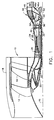
- Figure 1 is a schematic, longitudinal partly sectional view of an exemplary turbofan gas turbine engine having a counterrotating power turbine including rotating turbine frames in accordance with exemplary embodiments of the present invention.
- Figure 2 is an enlarged longitudinal, partly sectional view of the power turbine illustrated in Figure 1 showing in more detail forward and aft rotating turbine frames therein.
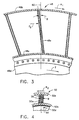
- Figure 3 is a radial, partly sectional view of a portion of the aft turbine frame illustrated in Figure 2 and taken along line 3-3.
- Figure 4 is a radial, partly sectional view of a portion of the forward turbine frame illustrated in Figure 2 and taken along line 4-4.
- FIG. 1 Illustrated in Figure 1 is an exemplary aircraft gas turbine engine 10 having an axially front fan 12 and an aft fan 14 disposed axially downstream therefrom about a longitudinal centerline axis 16.
- the fans 12, 14 include conventional rows of fan blades disposed within a conventional nacelle 18, with the blades being joined to respective rotor disks receiving power through a front fan shaft 20 joined to the front fan 12 and an aft fan shaft 22 joined to the aft fan 14.
- a conventional core engine 24 including a high pressure compressor (HPC) 26, combustor 28, and an exemplary two-stage core or high pressure turbine 30 joined to the HPC 26 by a core shaft 32.
- the core engine 24 conventionally generates combustion gases which flow downstream therefrom to a counter-rotating power turbine 34 which extracts energy therefrom for powering the fans 12, 14 through their respective fan shafts 20, 22.
- the power turbine 34 is illustrated in more particularity in Figure 2 and includes a stationary outer casing 36 conventionally joined to the core engine 24 at the core turbine 30.
- the power turbine 34 includes a radially outer rotor 38 in the form of a generally frustoconical drum having a plurality of conventional outer rotor blades 40 extending radially inwardly therefrom in axially spaced apart blade row stages, four being illustrated for example.
- a radially inner rotor 42 is disposed coaxially with the outer rotor 38 about the centerline axis 16 and includes a plurality of conventional inner rotor blades 44 extending radially outwardly therefrom in axially spaced apart blade row stages, four being shown for example, which are interdigitated with the outer blade stages, with blade stages of the respective outer and inner rotors 38, 42 being disposed axially between respective stages of the other rotor as is conventionally known.
- a rotor support system includes a stationary rear frame 46 disposed aft of the outer and inner blades 40, 44 of the power turbine 34.
- the rear frame 46 includes a plurality of conventional circumferentially spaced apart struts 46a joined at their outer ends to an annular outer band 46b which in turn is conventionally fixedly joined to the outer casing 36, and joined at their inner ends to an annular inner band or hub 46c.
- the rear frame 46 also includes an annular rear support shaft 46d extending radially inwardly therefrom.
- the rear struts 46a are disposed in flow communication with the aft end of the power turbine 34 for receiving the combustion gases therefrom and do not include conventional fairings surrounding the struts since the combustion gases are at a relatively low temperature.
- a rotatable aft frame 48 is disposed axially aft of the outer and inner blades 40, 44 and axially forward of the rear frame 46 and is fixedly joined to one of the outer and inner rotors 38, 42 for rotation therewith and for providing additional rigidity for supporting the blades thereof.
- the aft frame 48 includes a plurality of circumferentially spaced apart struts 48a fixedly joined to radially outer and inner annular aft bands 48b, 48c, with the inner aft band 48c being fixedly joined to an annular aft support shaft 48d for rotation therewith which extends radially inwardly therefrom and axially forward of the rear frame 46.
- the outer and inner bands 48b, 48c join together the several struts 48a for creating a relatively rigid assembly.
- the aft frame 48 at the inner band 48c is fixedly joined to the inner rotor 42.
- a rotatable annular forward frame 50 is disposed axially forward of the outer and inner blades 40, 44 and similarly includes a plurality of circumferentially spaced apart forward struts 50a fixedly joined to radially outer and inner annular front bands 50b, 50c, with the inner front band 50c being fixedly joined to an annular forward shaft 50d extending radially inwardly therefrom.
- the forward frame 50 at the outer band 50b is fixedly joined to the outer rotor 38 for rotation therewith.
- each of the forward struts 50a is enclosed by a conventional fairing 58 to protect the struts 50a from the hot combustion gases flowing therebetween.
- the outer band 50b of the forward frame 50 is joined to the outer rotor 38, and the inner band 48c of the aft frame 48 is joined to the inner rotor 42 in this exemplary embodiment
- the outer band 48b of the aft frame 48 could instead be joined to the outer rotor 38 with the inner band 48c being disconnected from the inner rotor 42
- the inner band 50c of the forward frame 50 would instead be joined to the inner rotor 42 with-the outer band 50b being disconnected from the outer rotor 38.
- the rear frame 48 is joined to one of the outer and inner rotors 38, 42 for rotation therewith, and the forward frame 50 is joined to the other thereof for rotation therewith.
- each of the frames 48, 50 is a relatively rigid structure since the respective struts thereof are joined to the respective outer and inner annular bands.
- the rigidity of the frames 48, 50 is used in accordance with the present invention to increase the rigidity of the respective rotors 38, 42 for decreasing the amount of blade tip clearance variation due to in-plane bending moments which occur during operation of the power turbine 34. Since the aft frame 48 is joined at its inner band 48c to the inner rotor 42 it increases the rigidity thereof. Similarly, since the forward frame 50 is joined at its outer band 50b to the outer rotor 38, it also increases the rigidity thereof.
- Blade tip clearances are further reduced by supporting the outer and inner rotors 38, 42 to the rear frame 46. Since the rear frame 46 is supported at its outer band 46b to the outer casing 36, it has a relatively large diameter with a correspondingly large structural rigidity.
- the power turbine 34 solely on the rear frame 46 instead of a conventional mid-frame (not shown) having a smaller diameter which is typically located between the core turbine 30 and the power turbine 34, an improved support system is created as well as providing close-coupling between the core turbine 30 and the power turbine 34 for channeling the combustion gases thereto with improved efficiency.
- the core turbine 30 is disposed axially forwardly of the outer and inner blades 40, 44 and may be positioned relatively close thereto by the elimination of the stationary mid-frame (not shown) typically used for supporting power turbines.
- a conventional first bearing 52 is disposed between the aft shaft 48d and the rear shaft 46d for supporting the aft shaft 48d on the rear shaft 46d.
- a conventional second bearing 54 is disposed between the forward shaft 50d and the aft shaft 48d for supporting the forward shaft 50d on the aft shaft 48d.
- a conventional third bearing 56 is disposed between the core shaft 32 and the forward shaft 50d for supporting the core shaft 32 on the forward shaft 50d.
- the first, second and third bearings 52, 54, 56 are preferably roller bearings, with the second bearing 24 being a differential-type bearing since it is mounted between the two counter-rotating shafts 48d, 50d. Other types of bearings may be used as desired.
- the rear frame 46 provides a substantially rigid support for both power turbine rotors 38 and 42 as well as the aft end of the core shaft 32.
- the rear shaft 46d is preferably frustoconical and extends axially forwardly from the rear frame 46 toward the aft shaft 48d.
- the aft shaft 48d is preferably frustoconical and extends axially forwardly toward the forward shaft 50d.
- the forward shaft 50d is also frustoconical but extends axially aft toward the aft shaft 48d. In this way, the additional rigidity due to a cone shape is obtained from each of the shafts 46d, 48d, and 50d.
- FIGS. 3 and 4 illustrate portions of the frames 48, 50 with the rear frame 48 in this exemplary embodiment rotating in a first, clockwise direction R 1 , and the forward frame 50 rotating in a second, opposite or counter-clockwise direction R 2 . Since the combustion gases are relatively cool upon reaching the rear frame 48, it does not include a fairing such as the fairing 58 on the forward frame 50.
- the fairings 58 surrounding the struts 50a of the forward frame 50 are conventionally configured for channeling the combustion gases therethrough, with the struts 50a having a suitable and typically symmetrical configuration therein.
- the output torque from the frames 48, 50 is designated T and is illustrated in the two drive shafts 48d, 50d illustrated in Figures 3 and 4.
- the struts 48a, 50a thereof experience centrifugally generated tensile loads and corresponding stress therein.
- the struts are backwardly radially inclined relative to their respective directions of rotation so that the gas flow between the respective struts 48a, 50a tends to straighten the inclined struts to effect a compressive load component therein which is subtracted from the tensile stresses generated in the struts due to centrifugal force.
- the aft struts 48a are inclined from the radial axis designated 60 in a second direction opposite to the direction of rotation R 1 at an acute inclination angle B.
- the forces exerted on the strut 48a from the combustion gases and designated F g tend to straighten the inclined struts 48a, or decrease the value of the inclination angle B, which are confined between the outer and inner bands 48b, 48c.
- This constraint will effect a compressive load component through the struts 48a to generate a respective compressive stress component which is subtracted from the centrifugally generated tensile stresses therein for reducing the overall stresses within the struts 48a.
- the majority of the total torque T carried by the aft drive shaft 48d is generated by the inner blades 44 and is carried thereto from the inner rotor 42.
- the inner rotor 42 is fixedly joined to the inner band 48c at the drive shaft 48d with an additional component of the torque T being generated by the aft struts 48a for effecting the compressive load component therein.
- the fairings 58 surround the struts 50a and therefore the gas loads act upon the fairings 58 and in turn are carried through the outer band 50b which also tends to straighten the inclined strut 50a.
- the outer and inner bands 50b, 50c constrain the struts 50a from straightening which effects a compressive load component in a similar fashion to that generated in the aft frame 48.
- the forward struts 50a and the fairings 58 may be conventionally configured for not turning the combustion gases therethrough, and therefore without effecting gas loads thereon.
- the torque T from the outer rotor 38 generated by the outer blades 40 is channeled through the outer band 50b and in turn through the struts 50a to the inner band 50c and in turn to the forward drive shaft 50d.
- the torque T will tend to straighten the struts 50a, by reducing the inclination angle B, and therefore generate the compressive load component therein which again is subtracted from the centrifugally generated tensile loads therein.
Claims (6)
- Cadre de turbine rotatif (48, 50) pour un moteur (10) à turbine à gaz comprenant :une bande extérieure annulaire (48b, 50b);une bande intérieure annulaire (48c, 50c) espacée radialement de ladite bande extérieure (48b, 50b) vers l'intérieur et disposée coaxialement à cette dernière;une pluralité d'entretoises (48a, 50a) espacées dans le sens de la circonférence et s'étendant radialement entre lesdites bandes extérieure et intérieure (48b,c, 50b,c) et reliées fixement à ces dernières;un arbre d'entraînement annulaire (48d, 50d) relié fixement à ladite bande intérieure (48c, 50c) pour transmettre le couple de sortie lors de la rotation dudit cadre (48, 50) dans une première direction lors de l'écoulement des gaz entre lesdites entretoises (48a, 50a); etlesdites entretoises (48a, 50a) étant inclinées radialement dans une deuxième direction opposée à ladite première direction de manière que ledit écoulement des gaz entre lesdites entretoises (48a, 50a) ait tendance à redresser lesdites entretoises inclinées (48a, 50a) afin d'y créer une charge de compression.
- Cadre de turbine selon la revendication 1, en combinaison avec un rotor annulaire (38, 42) qui y est relié fixement et comportant une pluralité d'étages d'aubes (40, 44) de rotor destinés à faire tourner ledit arbre d'entraînement (48d, 50d).
- Combinaison de cadres de turbine selon la revendication 2, dans lequel ledit rotor est un rotor radialement intérieur (42) relié fixement à ladite bande intérieure (48c) au niveau dudit arbre d'entraînement (48d).
- Combinaison de cadres de turbine selon la revendication 2, dans lequel ledit rotor est un rotor radialement extérieur (38) relié fixement à ladite bande extérieure (50b).
- Combinaison de cadres de turbine selon la revendication 2 comprenant, en outre:ledit cadre de turbine est configuré comme un cadre de turbine avant (48) et dans lequel ledit rotor est un rotor radialement intérieur (42) relié de façon fixe à ladite bande intérieure (48c), lesdites aubes intérieures (44) s'étendant radialement vers l'extérieur depuis ledit rotor intérieur (42) et ledit arbre d'entraînement est un arbre d'entraînement avant (48d) et comprenant, en outre:un autre desdits cadres de turbine configuré comme un cadre de turbine avant (50) et dans lequel ledit rotor de ce cadre est un rotor radialement extérieur (38) disposé coaxialement audit rotor intérieur (42), lesdites aubes de ce cadre sont des aubes extérieures (40) s'étendant radialement vers l'intérieur depuis ledit rotor extérieur (38) et ledit arbre d'entraînement de ce dernier est un arbre d'entraînement avant (50) espacé axialement vers l'avant dudit arbre d'entraînement arrière (48d) etlesdits rotors intérieur et extérieur (42, 38) sont configuré en vue d'une rotation antagoniste.
- Combinaison de cadre de turbine selon la revendication 2, comprenant une pluralité de carénages (58) entourant chacun une entretoise correspondante desdites entretoises (50a).
Applications Claiming Priority (2)
| Application Number | Priority Date | Filing Date | Title |
|---|---|---|---|
| US80669 | 1993-06-18 | ||
| US08/080,669 US5443590A (en) | 1993-06-18 | 1993-06-18 | Rotatable turbine frame |
Publications (2)
| Publication Number | Publication Date |
|---|---|
| EP0631041A1 EP0631041A1 (fr) | 1994-12-28 |
| EP0631041B1 true EP0631041B1 (fr) | 1997-05-07 |
Family
ID=22158864
Family Applications (1)
| Application Number | Title | Priority Date | Filing Date |
|---|---|---|---|
| EP94304145A Expired - Lifetime EP0631041B1 (fr) | 1993-06-18 | 1994-06-09 | Cadre de turbine rotatif |
Country Status (4)
| Country | Link |
|---|---|
| US (1) | US5443590A (fr) |
| EP (1) | EP0631041B1 (fr) |
| JP (1) | JP2634772B2 (fr) |
| DE (1) | DE69403027T2 (fr) |
Cited By (1)
| Publication number | Priority date | Publication date | Assignee | Title |
|---|---|---|---|---|
| US8038388B2 (en) | 2007-03-05 | 2011-10-18 | United Technologies Corporation | Abradable component for a gas turbine engine |
Families Citing this family (81)
| Publication number | Priority date | Publication date | Assignee | Title |
|---|---|---|---|---|
| CN1087046C (zh) * | 1995-01-10 | 2002-07-03 | 普罗克特和甘保尔公司 | 平滑,穿透热风干燥的薄页纸和制造方法 |
| US6431476B1 (en) | 1999-12-21 | 2002-08-13 | Cepheid | Apparatus and method for rapid ultrasonic disruption of cells or viruses |
| US20040200909A1 (en) * | 1999-05-28 | 2004-10-14 | Cepheid | Apparatus and method for cell disruption |
| US6619030B1 (en) | 2002-03-01 | 2003-09-16 | General Electric Company | Aircraft engine with inter-turbine engine frame supported counter rotating low pressure turbine rotors |
| US6732502B2 (en) | 2002-03-01 | 2004-05-11 | General Electric Company | Counter rotating aircraft gas turbine engine with high overall pressure ratio compressor |
| US6739120B2 (en) | 2002-04-29 | 2004-05-25 | General Electric Company | Counterrotatable booster compressor assembly for a gas turbine engine |
| US6684626B1 (en) | 2002-07-30 | 2004-02-03 | General Electric Company | Aircraft gas turbine engine with control vanes for counter rotating low pressure turbines |
| US6711887B2 (en) | 2002-08-19 | 2004-03-30 | General Electric Co. | Aircraft gas turbine engine with tandem non-interdigitated counter rotating low pressure turbines |
| US6763652B2 (en) | 2002-09-24 | 2004-07-20 | General Electric Company | Variable torque split aircraft gas turbine engine counter rotating low pressure turbines |
| US6763653B2 (en) | 2002-09-24 | 2004-07-20 | General Electric Company | Counter rotating fan aircraft gas turbine engine with aft booster |
| US6763654B2 (en) | 2002-09-30 | 2004-07-20 | General Electric Co. | Aircraft gas turbine engine having variable torque split counter rotating low pressure turbines and booster aft of counter rotating fans |
| US7063505B2 (en) | 2003-02-07 | 2006-06-20 | General Electric Company | Gas turbine engine frame having struts connected to rings with morse pins |
| US6866479B2 (en) * | 2003-05-16 | 2005-03-15 | Mitsubishi Heavy Industries, Ltd. | Exhaust diffuser for axial-flow turbine |
| FR2858649B1 (fr) * | 2003-08-05 | 2005-09-23 | Snecma Moteurs | Turbine basse-pression de turbomachine |
| FR2866073B1 (fr) * | 2004-02-11 | 2006-07-28 | Snecma Moteurs | Turboreacteur ayant deux soufflantes contrarotatives solidaires d'un compresseur a basse pression contrarotatif |
| US7185484B2 (en) * | 2004-08-11 | 2007-03-06 | General Electric Company | Methods and apparatus for assembling a gas turbine engine |
| US7409819B2 (en) * | 2004-10-29 | 2008-08-12 | General Electric Company | Gas turbine engine and method of assembling same |
| US7195447B2 (en) * | 2004-10-29 | 2007-03-27 | General Electric Company | Gas turbine engine and method of assembling same |
| EP1825170B1 (fr) | 2004-12-01 | 2009-03-18 | United Technologies Corporation | Systeme de lubrification de boite de vitesses pour moteur a turbine d'extremite |
| US7980054B2 (en) * | 2004-12-01 | 2011-07-19 | United Technologies Corporation | Ejector cooling of outer case for tip turbine engine |
| WO2006059971A2 (fr) | 2004-12-01 | 2006-06-08 | United Technologies Corporation | Logement de moteur a turbine integrant un ventilateur, un combustor, et une turbine |
| WO2006110122A2 (fr) | 2004-12-01 | 2006-10-19 | United Technologies Corporation | Purgeur gonflable destine a un moteur a turbine |
| WO2006059985A1 (fr) | 2004-12-01 | 2006-06-08 | United Technologies Corporation | Compresseur axial pour moteur a turbine de bout |
| US7921635B2 (en) * | 2004-12-01 | 2011-04-12 | United Technologies Corporation | Peripheral combustor for tip turbine engine |
| DE602004023769D1 (de) * | 2004-12-01 | 2009-12-03 | United Technologies Corp | Gestapelte ringförmige bauteile für turbinenmotoren |
| WO2006060014A1 (fr) | 2004-12-01 | 2006-06-08 | United Technologies Corporation | Systeme de generateur-demarreur pour moteur de turbine a pression d’entree |
| WO2006059973A1 (fr) * | 2004-12-01 | 2006-06-08 | United Technologies Corporation | Moteur de turbine a aube comprenant un echangeur thermique |
| US9003759B2 (en) | 2004-12-01 | 2015-04-14 | United Technologies Corporation | Particle separator for tip turbine engine |
| WO2006059989A1 (fr) | 2004-12-01 | 2006-06-08 | United Technologies Corporation | Structure de support de moteur a turbine de bout |
| US8807936B2 (en) | 2004-12-01 | 2014-08-19 | United Technologies Corporation | Balanced turbine rotor fan blade for a tip turbine engine |
| US7874802B2 (en) | 2004-12-01 | 2011-01-25 | United Technologies Corporation | Tip turbine engine comprising turbine blade clusters and method of assembly |
| DE602004031986D1 (de) | 2004-12-01 | 2011-05-05 | United Technologies Corp | Gebläse-turbinen-rotoranordnung für einen spitzenturbinenmotor |
| WO2006059970A2 (fr) | 2004-12-01 | 2006-06-08 | United Technologies Corporation | Moteur a turbine equipe d'un ventilateur et d'un compresseur entraines par un engrenage differentiel |
| DE602004028528D1 (de) * | 2004-12-01 | 2010-09-16 | United Technologies Corp | Tip-Turbinentriebwerk mit mehreren Gebläse- und Turbinenstufen |
| US7883315B2 (en) | 2004-12-01 | 2011-02-08 | United Technologies Corporation | Seal assembly for a fan rotor of a tip turbine engine |
| US8096753B2 (en) | 2004-12-01 | 2012-01-17 | United Technologies Corporation | Tip turbine engine and operating method with reverse core airflow |
| WO2006059994A1 (fr) | 2004-12-01 | 2006-06-08 | United Technologies Corporation | Ensemble de joint pour rotor de turbine-ventilateur de moteur de turbine a pression d’entree |
| EP1828547B1 (fr) | 2004-12-01 | 2011-11-30 | United Technologies Corporation | Turbosoufflante comprenant une pluralité d'aubes directrices d'entrée commandées individuellement et procédé de commande associé |
| US7882694B2 (en) | 2004-12-01 | 2011-02-08 | United Technologies Corporation | Variable fan inlet guide vane assembly for gas turbine engine |
| WO2006060010A1 (fr) * | 2004-12-01 | 2006-06-08 | United Technologies Corporation | Pale de guidage d’entree de compresseur pour moteur de turbine a pression d’entree et procede de commande correspondant |
| US7921636B2 (en) * | 2004-12-01 | 2011-04-12 | United Technologies Corporation | Tip turbine engine and corresponding operating method |
| US8061968B2 (en) | 2004-12-01 | 2011-11-22 | United Technologies Corporation | Counter-rotating compressor case and assembly method for tip turbine engine |
| US7959406B2 (en) | 2004-12-01 | 2011-06-14 | United Technologies Corporation | Close coupled gearbox assembly for a tip turbine engine |
| EP1825113B1 (fr) * | 2004-12-01 | 2012-10-24 | United Technologies Corporation | Boîte de vitesses contre-rotative pour moteur à turbine en bout |
| WO2006059972A1 (fr) | 2004-12-01 | 2006-06-08 | United Technologies Corporation | Commande à distance d'étage variable de compresseur pour moteur à turbine |
| US7959532B2 (en) | 2004-12-01 | 2011-06-14 | United Technologies Corporation | Hydraulic seal for a gearbox of a tip turbine engine |
| WO2006059990A1 (fr) | 2004-12-01 | 2006-06-08 | United Technologies Corporation | Refroidissement regeneratif des aubes et pales de turbine pour moteur a turbine d'extremite |
| US7631480B2 (en) | 2004-12-01 | 2009-12-15 | United Technologies Corporation | Modular tip turbine engine |
| WO2006060011A1 (fr) | 2004-12-01 | 2006-06-08 | United Technologies Corporation | Moteur a turbine de pointe comprenant un compartiment non rotatif |
| US8468795B2 (en) * | 2004-12-01 | 2013-06-25 | United Technologies Corporation | Diffuser aspiration for a tip turbine engine |
| US8152469B2 (en) | 2004-12-01 | 2012-04-10 | United Technologies Corporation | Annular turbine ring rotor |
| US7882695B2 (en) | 2004-12-01 | 2011-02-08 | United Technologies Corporation | Turbine blow down starter for turbine engine |
| US8024931B2 (en) | 2004-12-01 | 2011-09-27 | United Technologies Corporation | Combustor for turbine engine |
| WO2006060006A1 (fr) | 2004-12-01 | 2006-06-08 | United Technologies Corporation | Cone arriere non metallique de moteur a turbine de bout |
| WO2006060003A2 (fr) | 2004-12-01 | 2006-06-08 | United Technologies Corporation | Pale de ventilateur comprenant une section de diffuseur integrale et une section de pale de turbine a aube destine a une moteur a turbine a aube |
| EP1825112B1 (fr) | 2004-12-01 | 2013-10-23 | United Technologies Corporation | Moteur a turbine de bout en porte-a-faux |
| WO2006059979A1 (fr) | 2004-12-01 | 2006-06-08 | United Technologies Corporation | Carter intégral, aube fixe, bâti et mélangeur d'un moteur à turbine en bout |
| WO2006110123A2 (fr) * | 2004-12-01 | 2006-10-19 | United Technologies Corporation | Conduit de transition pour moteur a turbine |
| EP1834076B1 (fr) | 2004-12-01 | 2011-04-06 | United Technologies Corporation | Groupe d'aubes de turbine d'un rotor de soufflante et procédé de montage d'un tel groupe |
| WO2006062497A1 (fr) | 2004-12-04 | 2006-06-15 | United Technologies Corporation | Bâti moteur à turbine en bout de pale |
| US7510371B2 (en) * | 2005-06-06 | 2009-03-31 | General Electric Company | Forward tilted turbine nozzle |
| US7594388B2 (en) * | 2005-06-06 | 2009-09-29 | General Electric Company | Counterrotating turbofan engine |
| US7513102B2 (en) * | 2005-06-06 | 2009-04-07 | General Electric Company | Integrated counterrotating turbofan |
| FR2912181B1 (fr) * | 2007-02-07 | 2009-04-24 | Snecma Sa | Turbine a gaz a turbines hp et bp contra-rotatives |
| US8967945B2 (en) | 2007-05-22 | 2015-03-03 | United Technologies Corporation | Individual inlet guide vane control for tip turbine engine |
| BR102013021427B1 (pt) * | 2013-08-16 | 2022-04-05 | Luis Antonio Waack Bambace | Turbomáquinas axiais de carcaça rotativa e elemento central fixo |
| KR101684778B1 (ko) * | 2015-04-16 | 2016-12-08 | 한양대학교 산학협력단 | 진동 특성 해석 시스템 및 진동 특성 해석 방법 |
| PL415534A1 (pl) * | 2016-01-04 | 2017-07-17 | General Electric Company | Układ dla zespołu osłony i przegrody wstępnych łopatek kierowniczych |
| US10544734B2 (en) * | 2017-01-23 | 2020-01-28 | General Electric Company | Three spool gas turbine engine with interdigitated turbine section |
| US10655537B2 (en) * | 2017-01-23 | 2020-05-19 | General Electric Company | Interdigitated counter rotating turbine system and method of operation |
| US10539020B2 (en) * | 2017-01-23 | 2020-01-21 | General Electric Company | Two spool gas turbine engine with interdigitated turbine section |
| US10605168B2 (en) | 2017-05-25 | 2020-03-31 | General Electric Company | Interdigitated turbine engine air bearing cooling structure and method of thermal management |
| US10718265B2 (en) | 2017-05-25 | 2020-07-21 | General Electric Company | Interdigitated turbine engine air bearing and method of operation |
| US10787931B2 (en) | 2017-05-25 | 2020-09-29 | General Electric Company | Method and structure of interdigitated turbine engine thermal management |
| US10669893B2 (en) | 2017-05-25 | 2020-06-02 | General Electric Company | Air bearing and thermal management nozzle arrangement for interdigitated turbine engine |
| US10961850B2 (en) * | 2017-09-19 | 2021-03-30 | General Electric Company | Rotatable torque frame for gas turbine engine |
| US11085309B2 (en) * | 2017-09-22 | 2021-08-10 | General Electric Company | Outer drum rotor assembly |
| FR3101103B1 (fr) * | 2019-09-24 | 2022-04-22 | Safran Aircraft Engines | architecture améliorée de carter tournant de turbine contrarotative |
| US11268394B2 (en) | 2020-03-13 | 2022-03-08 | General Electric Company | Nozzle assembly with alternating inserted vanes for a turbine engine |
| US11428160B2 (en) | 2020-12-31 | 2022-08-30 | General Electric Company | Gas turbine engine with interdigitated turbine and gear assembly |
| DE102022113096A1 (de) | 2022-05-24 | 2023-11-30 | ConBotics GmbH | Mobile Robotervorrichtungen und Verfahren zur bahnförmigen Oberflächenbearbeitung von Gebäudestrukturen |
Family Cites Families (15)
| Publication number | Priority date | Publication date | Assignee | Title |
|---|---|---|---|---|
| BE357126A (fr) * | 1929-01-04 | |||
| GB586570A (en) * | 1943-03-18 | 1947-03-24 | Karl Baumann | Improvements in internal combustion turbine plant for propulsion |
| US2962260A (en) * | 1954-12-13 | 1960-11-29 | United Aircraft Corp | Sweep back in blading |
| DE1235072B (de) * | 1963-03-07 | 1967-02-23 | Daimler Benz Ag | Nachgiebige Lagergehaeuseaufhaengung an der Aussenwand eines Gasturbinentriebwerks |
| US3883264A (en) * | 1971-04-08 | 1975-05-13 | Gadicherla V R Rao | Quiet fan with non-radial elements |
| US3903690A (en) * | 1973-02-12 | 1975-09-09 | Gen Electric | Turbofan engine lubrication means |
| GB2114669B (en) * | 1982-02-12 | 1985-01-16 | Rolls Royce | Gas turbine engine bearing support structure |
| DE3237669A1 (de) * | 1982-10-11 | 1984-04-12 | Brown, Boveri & Cie Ag, 6800 Mannheim | Axialstroemungsmaschine |
| US5079916A (en) * | 1982-11-01 | 1992-01-14 | General Electric Company | Counter rotation power turbine |
| GB2192237B (en) * | 1986-07-02 | 1990-05-16 | Rolls Royce Plc | Gas turbine engine power turbine |
| US4790133A (en) * | 1986-08-29 | 1988-12-13 | General Electric Company | High bypass ratio counterrotating turbofan engine |
| US4860537A (en) * | 1986-08-29 | 1989-08-29 | Brandt, Inc. | High bypass ratio counterrotating gearless front fan engine |
| GB2194593B (en) * | 1986-08-29 | 1991-05-15 | Gen Electric | High bypass ratio, counter rotating gearless front fan engine |
| US5197281A (en) * | 1990-04-03 | 1993-03-30 | General Electric Company | Interstage seal arrangement for airfoil stages of turbine engine counterrotating rotors |
| US5080555A (en) * | 1990-11-16 | 1992-01-14 | General Motors Corporation | Turbine support for gas turbine engine |
-
1993
- 1993-06-18 US US08/080,669 patent/US5443590A/en not_active Expired - Lifetime
-
1994
- 1994-06-09 DE DE69403027T patent/DE69403027T2/de not_active Expired - Lifetime
- 1994-06-09 EP EP94304145A patent/EP0631041B1/fr not_active Expired - Lifetime
- 1994-06-16 JP JP6133509A patent/JP2634772B2/ja not_active Expired - Fee Related
Cited By (1)
| Publication number | Priority date | Publication date | Assignee | Title |
|---|---|---|---|---|
| US8038388B2 (en) | 2007-03-05 | 2011-10-18 | United Technologies Corporation | Abradable component for a gas turbine engine |
Also Published As
| Publication number | Publication date |
|---|---|
| DE69403027D1 (de) | 1997-06-12 |
| US5443590A (en) | 1995-08-22 |
| EP0631041A1 (fr) | 1994-12-28 |
| JP2634772B2 (ja) | 1997-07-30 |
| DE69403027T2 (de) | 1998-02-26 |
| JPH07145741A (ja) | 1995-06-06 |
Similar Documents
| Publication | Publication Date | Title |
|---|---|---|
| EP0631041B1 (fr) | Cadre de turbine rotatif | |
| EP0634569B1 (fr) | Système de support pour rotors de turbine à gaz | |
| US5307622A (en) | Counterrotating turbine support assembly | |
| US7334981B2 (en) | Counter-rotating gas turbine engine and method of assembling same | |
| EP0704601B1 (fr) | Bouclier thermique combiné avec dispositif de retention pour boulon d'assemblage de turbine | |
| EP1655457B1 (fr) | Turbine à gaz et procédé pour son montage | |
| US5160251A (en) | Lightweight engine turbine bearing support assembly for withstanding radial and axial loads | |
| JP4101496B2 (ja) | ファン連結解除ヒューズ | |
| US6073439A (en) | Ducted fan gas turbine engine | |
| US10584751B2 (en) | Load reduction assemblies for a gas turbine engine | |
| EP1655475B1 (fr) | Moteur à turbine à gaz contrarotative | |
| JP4396886B2 (ja) | モールスピンによりリングに結合されたストラットを有するガスタービンエンジンフレーム | |
| US5074109A (en) | Low pressure turbine rotor suspension in a twin hub turbo-engine | |
| US6447248B1 (en) | Bearing support fuse | |
| US8167531B2 (en) | Method and apparatus for supporting rotor assemblies during unbalances | |
| US20060093467A1 (en) | Counter-rotating gas turbine engine and method of assembling same | |
| EP1191191A2 (fr) | Palier de turbine | |
| US20030210979A1 (en) | Method and apparatus for supporting rotor assemblies during unbalances | |
| US6079200A (en) | Ducted fan gas turbine engine with fan shaft frangible connection | |
| US6375421B1 (en) | Piggyback rotor blisk | |
| US5236303A (en) | Gas turbine engine structural frame with multi-clevis ring attachment of struts to outer casing | |
| JP2012233474A (ja) | タービンエンジン及びその荷重低減装置 | |
| GB2259551A (en) | Gas turbine engine polygonal structural frame with axially curved panels |
Legal Events
| Date | Code | Title | Description |
|---|---|---|---|
| PUAI | Public reference made under article 153(3) epc to a published international application that has entered the european phase |
Free format text: ORIGINAL CODE: 0009012 |
|
| AK | Designated contracting states |
Kind code of ref document: A1 Designated state(s): DE FR GB IT |
|
| 17P | Request for examination filed |
Effective date: 19950628 |
|
| GRAG | Despatch of communication of intention to grant |
Free format text: ORIGINAL CODE: EPIDOS AGRA |
|
| 17Q | First examination report despatched |
Effective date: 19960802 |
|
| GRAH | Despatch of communication of intention to grant a patent |
Free format text: ORIGINAL CODE: EPIDOS IGRA |
|
| GRAH | Despatch of communication of intention to grant a patent |
Free format text: ORIGINAL CODE: EPIDOS IGRA |
|
| GRAA | (expected) grant |
Free format text: ORIGINAL CODE: 0009210 |
|
| AK | Designated contracting states |
Kind code of ref document: B1 Designated state(s): DE FR GB IT |
|
| ET | Fr: translation filed | ||
| REF | Corresponds to: |
Ref document number: 69403027 Country of ref document: DE Date of ref document: 19970612 |
|
| PLBE | No opposition filed within time limit |
Free format text: ORIGINAL CODE: 0009261 |
|
| STAA | Information on the status of an ep patent application or granted ep patent |
Free format text: STATUS: NO OPPOSITION FILED WITHIN TIME LIMIT |
|
| 26N | No opposition filed | ||
| REG | Reference to a national code |
Ref country code: GB Ref legal event code: IF02 |
|
| PGFP | Annual fee paid to national office [announced via postgrant information from national office to epo] |
Ref country code: GB Payment date: 20060626 Year of fee payment: 13 |
|
| GBPC | Gb: european patent ceased through non-payment of renewal fee |
Effective date: 20070609 |
|
| PG25 | Lapsed in a contracting state [announced via postgrant information from national office to epo] |
Ref country code: GB Free format text: LAPSE BECAUSE OF NON-PAYMENT OF DUE FEES Effective date: 20070609 |
|
| PGFP | Annual fee paid to national office [announced via postgrant information from national office to epo] |
Ref country code: FR Payment date: 20100630 Year of fee payment: 17 |
|
| PGFP | Annual fee paid to national office [announced via postgrant information from national office to epo] |
Ref country code: IT Payment date: 20100629 Year of fee payment: 17 Ref country code: DE Payment date: 20100629 Year of fee payment: 17 |
|
| PG25 | Lapsed in a contracting state [announced via postgrant information from national office to epo] |
Ref country code: IT Free format text: LAPSE BECAUSE OF NON-PAYMENT OF DUE FEES Effective date: 20110609 |
|
| REG | Reference to a national code |
Ref country code: FR Ref legal event code: ST Effective date: 20120229 |
|
| REG | Reference to a national code |
Ref country code: DE Ref legal event code: R119 Ref document number: 69403027 Country of ref document: DE Effective date: 20120103 |
|
| PG25 | Lapsed in a contracting state [announced via postgrant information from national office to epo] |
Ref country code: FR Free format text: LAPSE BECAUSE OF NON-PAYMENT OF DUE FEES Effective date: 20110630 Ref country code: DE Free format text: LAPSE BECAUSE OF NON-PAYMENT OF DUE FEES Effective date: 20120103 |