EP1655457B1 - Turbine à gaz et procédé pour son montage - Google Patents
Turbine à gaz et procédé pour son montage Download PDFInfo
- Publication number
- EP1655457B1 EP1655457B1 EP05256517A EP05256517A EP1655457B1 EP 1655457 B1 EP1655457 B1 EP 1655457B1 EP 05256517 A EP05256517 A EP 05256517A EP 05256517 A EP05256517 A EP 05256517A EP 1655457 B1 EP1655457 B1 EP 1655457B1
- Authority
- EP
- European Patent Office
- Prior art keywords
- turbine
- coupled
- bearing
- gas turbine
- spokes
- Prior art date
- Legal status (The legal status is an assumption and is not a legal conclusion. Google has not performed a legal analysis and makes no representation as to the accuracy of the status listed.)
- Expired - Fee Related
Links
Images

Classifications
-
- F—MECHANICAL ENGINEERING; LIGHTING; HEATING; WEAPONS; BLASTING
- F02—COMBUSTION ENGINES; HOT-GAS OR COMBUSTION-PRODUCT ENGINE PLANTS
- F02C—GAS-TURBINE PLANTS; AIR INTAKES FOR JET-PROPULSION PLANTS; CONTROLLING FUEL SUPPLY IN AIR-BREATHING JET-PROPULSION PLANTS
- F02C3/00—Gas-turbine plants characterised by the use of combustion products as the working fluid
- F02C3/04—Gas-turbine plants characterised by the use of combustion products as the working fluid having a turbine driving a compressor
- F02C3/06—Gas-turbine plants characterised by the use of combustion products as the working fluid having a turbine driving a compressor the compressor comprising only axial stages
- F02C3/067—Gas-turbine plants characterised by the use of combustion products as the working fluid having a turbine driving a compressor the compressor comprising only axial stages having counter-rotating rotors
-
- F—MECHANICAL ENGINEERING; LIGHTING; HEATING; WEAPONS; BLASTING
- F01—MACHINES OR ENGINES IN GENERAL; ENGINE PLANTS IN GENERAL; STEAM ENGINES
- F01D—NON-POSITIVE DISPLACEMENT MACHINES OR ENGINES, e.g. STEAM TURBINES
- F01D25/00—Component parts, details, or accessories, not provided for in, or of interest apart from, other groups
- F01D25/16—Arrangement of bearings; Supporting or mounting bearings in casings
- F01D25/162—Bearing supports
-
- F—MECHANICAL ENGINEERING; LIGHTING; HEATING; WEAPONS; BLASTING
- F05—INDEXING SCHEMES RELATING TO ENGINES OR PUMPS IN VARIOUS SUBCLASSES OF CLASSES F01-F04
- F05D—INDEXING SCHEME FOR ASPECTS RELATING TO NON-POSITIVE-DISPLACEMENT MACHINES OR ENGINES, GAS-TURBINES OR JET-PROPULSION PLANTS
- F05D2230/00—Manufacture
- F05D2230/60—Assembly methods
- F05D2230/64—Assembly methods using positioning or alignment devices for aligning or centring, e.g. pins
Definitions
- This invention relates generally to aircraft gas turbine engines, and more specifically to a gas turbine engine and a method of assembling same.
- At least one known gas turbine engine includes, in serial flow arrangement, a forward fan assembly, an aft fan assembly, a high-pressure compressor for compressing air flowing through the engine, a combustor for mixing fuel with the compressed air such that the mixture may be ignited, and a high-pressure turbine.
- the high-pressure compressor, combustor and high-pressure turbine are sometimes collectively referred to as the core engine.
- the core engine generates combustion gases which are discharged downstream to a counter-rotating low-pressure turbine that extracts energy therefrom for powering the forward and aft fan assemblies.
- at least one turbine rotates in an opposite direction than the other rotating components within the engine
- At least one known counter-rotating low-pressure turbine has an inlet radius that is larger than a radius of the high-pressure turbine discharge. The increased inlet radius accommodates additional rotor stages within the low-pressure turbine.
- at least one known counter-rotating low-pressure turbine includes an outer rotor having a first quantity of stages that are rotatably coupled to the forward fan assembly, and an inner rotor having an equal number of stages that is rotatably coupled to the aft fan assembly.
- such known gas turbine engines are assembled such that the outer rotor is cantilevered from the turbine rear-frame. More specifically, the first quantity of rows stages are each coupled together and to the rotating casing to form the outer rotor.
- the outer rotor is then coupled to the turbine rear-frame using only the last stage of the outer rotor, such that only the last stage of the outer rotor supports the combined weight of the outer rotor and the rotating casing.
- the inner rotor is coupled to a shaft to facilitate driving at least one fan assembly.
- the inner rotor is rotatably coupled to a turbine mid-frame using at least one bearing.
- EP-A-1 340 902 discloses a low pressure turbine having counter rotating low pressure inner and outer rotors, an inter-turbine frame comprising first and second structural rings and a bearing rotatably supporting the inner and outer rotors.
- US-A-4 979 872 discloses a support structure for the bearing compartment of a gas turbine engine.
- GB-A-2 112 084 discloses a bearing support structure.
- the bearing must be properly aligned with respect to the turbine mid-frame to properly position the inner rotor within the gas turbine.
- properly positioning the bearing within the gas turbine engine results in an increased time required to assemble the gas turbine engine.
- thermal expansion of the engine may result in a misalignment of the bearing with respect to the gas turbine engine outer casing.
- a method for assembling a gas turbine engine includes providing a low-pressure turbine inner rotor that includes a first plurality of turbine blade rows configured to rotate in a first direction, providing a low-pressure turbine outer rotor that includes a second plurality of turbine blade rows configured to rotate in a second direction that is opposite the first direction, coupling a turbine mid-frame assembly including a plurality of spokes within the engine such that the spokes are spaced axially forward of the inner rotor, coupling a bearing between the turbine mid-frame assembly and the inner rotor such that the inner rotor is rotatably coupled to the turbine mid-frame, and adjusting the plurality of spokes to align the bearing in a radial direction.
- a low-pressure turbine in another embodiment, includes an inner rotor including a first plurality of turbine blade rows configured to rotate in a first direction, an outer rotor including a second plurality of turbine blade rows configured to rotate in a second direction that is opposite the first direction, a turbine mid-frame assembly including a plurality of spokes, and a bearing coupled to the turbine mid-frame assembly and the inner rotor, wherein the spokes are adjustable to align the bearing in a radial direction.
- a gas turbine engine in a further embodiment of the invention, includes an inner rotor including a first plurality of turbine blade rows configured to rotate in a first direction, an outer rotor including a second plurality of turbine blade rows configured to rotate in a second direction that is opposite the first direction, a turbine mid-frame assembly including a plurality of spokes, and a bearing coupled to the turbine mid-frame assembly and the inner rotor, wherein the spokes are adjustable to align the bearing in a radial direction.
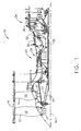
- FIG. 1 is a cross-sectional view of an exemplary gas turbine engine 10 that includes a forward fan assembly 12 and an aft fan assembly 14 disposed about a longitudinal centerline axis 16.
- the terms "forward fan” and “aft fan” are used herein to indicate that one of the fans 12 is coupled axially upstream from the other fan 14.
- fan assemblies 12 and 14 are positioned at a forward end of gas turbine engine 10 as illustrated.
- fan assemblies 12 and 14 are positioned at an aft end of gas turbine engine 10.
- Fan assemblies 12 and 14 each include a plurality of rows of fan blades 19 positioned within a nacelle 18. Blades 19 are joined to respective rotor disks 21 that are rotatably coupled through a respective fan shaft 20 to forward fan assembly 12 and through a fan shaft 22 to aft fan assembly 14.
- Gas turbine engine 10 also includes a core engine 24 that is downstream from fan assemblies 12 and 14.
- Core engine 24 includes a high-pressure compressor (HPC) 26, a combustor 28, and a high-pressure turbine (HPT) 30 that is coupled to HPC 26 via a core rotor or shaft 32.
- HPC high-pressure compressor
- HPT high-pressure turbine
- core engine 24 generates combustion gases that are channeled downstream to a counter-rotating low-pressure turbine 34 which extracts energy from the gases for powering fan assemblies 12 and 14 through their respective fan shafts 20 and 22.
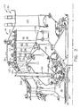
- FIG 2 is a cross-sectional view of a portion of gas turbine engine 10 (shown in Figure 1).
- Figure 3 is an end view of gas turbine engine 10.
- low-pressure turbine 34 includes a radially outer rotor 110 that is positioned radially inwardly of outer casing 36.
- Outer rotor 110 has a generally frusto-conical shape and includes a plurality of circumferentially-spaced rotor blades 112 that extend radially inwardly. Blades 112 are arranged in axially-spaced rows 114.
- outer rotor 110 may have any quantity of rows 114 of blades 112 without affecting the scope of the method and apparatus described herein. More specifically, outer rotor 110 includes M rows 114 of blades 112.
- Low-pressure turbine 34 also includes a radially inner rotor 120 that is aligned substantially coaxially with respect to, and radially inward of, outer rotor 110.
- Inner rotor 120 includes a plurality of circumferentially-spaced rotor blades 122 that extend radially outwardly and are arranged in axially-spaced rows 124.
- inner rotor blades 122 within rows 124 are axially-interdigitated with outer rotor blades 112 within rows 114 such that inner rotor rows 124 extend between respective outer rotor rows 114. Blades 112 and 122 are therefore configured for counter-rotation of rotors 110 and 120.
- low-pressure turbine 34 also includes a rotor support assembly 130 that includes a stationary annular turbine rear-frame 132 that is aft of low-pressure turbine outer and inner blades 112 and 122.
- a rotatable aft frame 134 is positioned aft of outer and inner blades 112 and 122, and upstream from turbine rear-frame 132.
- Frame 134 is coupled to an aft end of outer rotor 110 for rotation therewith and to facilitate providing additional rigidity for supporting blades 112.
- Shaft 22 is rotatably coupled between inner rotor 120 and fan 14 such that inner rotor 120 is rotatably coupled to fan 14.
- a first shaft bearing 140 is coupled to shaft 22 such that the weight of inner rotor 120 is distributed substantially equally about the circumference of gas turbine engine 10 via a spoked turbine mid-frame 150, and such that high-pressure turbine is rotatably coupled to turbine mid-frame 150 through a bearing 142.
- gas turbine engine 10 includes a first housing 160 that is coupled to bearing 140 and a second housing 162 that is coupled to bearing 142.
- Bearing 140 is positioned between high-pressure turbine 30 and shaft 22. Housings 160 and 162 are coupled together to form a hub assembly 170.
- housings 160 and 162 are coupled together using a mechanical fastener 172, such as a nut and bolt, for example. Accordingly, and in the exemplary embodiment, turbine mid-frame 150 facilitates supporting low-pressure turbine 34 and high-pressure turbine 30.
- Turbine mid-frame 150 includes a plurality of yokes 180 that are coupled to hub 170. Although only eight yokes 180 are shown, it should be realized that turbine mid-frame 150 may have any quantity of yokes 180 without affecting the scope of the methods and/or apparatus described herein.
- Each yoke 180 is substantially ⁇ -shaped and includes at least one opening 182 formed therein.
- each yoke 180 includes a pair of openings 182 that are each selectively sized to receive an expandable pin 184 therein. Pins 184 are used to couple a spoke 186 to each respective yoke 180.
- turbine mid-frame 150 includes eight spokes 186 that are each coupled to hub 170 using yokes 180 and pins 184. More specifically, each respective spoke 186 includes a first end 190 that is coupled to a respective yoke 180 using pins 184, and a second end 192 that extends through a respective opening 194 formed in outer casing 36. Accordingly, in the exemplary embodiment, outer casing 36 includes eight openings 194 that are each sized to receive a respective spoke 186.
- each respective spoke second end 192 is threaded and selectively sized to receive a washer 196, a first mechanical fastener 197, and a second mechanical fastener 198.
- washer 196 is at least one of a belleville or a wave-type washer that is substantially cone-shaped
- mechanical fastener 197 is a spanner nut
- mechanical fastener 198 is a lock nut.
- hub assembly 170 is coupled to spokes 186 using yokes 180 and pins 184.
- Each respective mechanical fastener 197 is coupled to a respective spoke 186 such that washer 196 is at least partially compressed against casing 36. More specifically, compressing each washer 196 against casing 36 induces tension into each respective spoke 186 to facilitate controlling the relative radial position of bearing 140.
- Each respective spoke 186 is then retained in position as each fastener 198 is tightened against each respective fastener 197 such that fastener 197 is held in a relatively constant position with respect to each respective spoke 186.
- gas turbine engine 10 also includes a plurality of fairings 200. More specifically, each respective fairing 200 is positioned around each respective spoke 186, such that each fairing 200 facilitates channeling air around each respective spoke. 186.
- turbine mid-frame 150 facilitates maintaining bearing 140 in a relatively constant axial and radial position with respect to casing 36.
- washer 196 either expands or contracts to facilitate compensating for a thermal expansion of gas turbine engine 10. More specifically, and in the exemplary embodiment, washer 196 functions as a spring to facilitate maintaining bearing 140 in a relatively constant axial and radial position when engine 10 is either expanding or contracting due to thermal expansion.
- a counter-rotating low-pressure turbines including an adjustable turbine mid-frame are described above in detail.
- the components are not limited to the specific embodiments described herein, but rather, components of each system may be utilized independently and separately from other components described herein.
- the adjustable turbine mid-frame described herein can also be used in combination with other known gas turbine engines.
Claims (7)
- Turbine basse pression (34) comprenant :un rotor interne (120) comprenant une première pluralité de rangées (124) de pales de turbine configurées pour tourner dans une première direction;un rotor externe (110) comprenant une deuxième pluralité de rangées (114) de pales de turbine configurées pour tourner dans une deuxième direction qui est opposée à ladite première direction ;un ensemble demi-cadre (150) de turbine comprenant une pluralité de rayons (186) ; un ensemble moyeu (170) ; et au moins une culasse (180) couplée audit ensemble moyeu ;deux chevilles expansibles (184) configurées pour coupler chacun parmi ladite pluralité de rayons (186) à une culasse respective ; etun palier (140) couplé audit ensemble demi-cadre de turbine et audit rotor interne, lesdits rayons étant réglables pour aligner ledit palier dans une direction radiale.
- Turbine basse pression (34) selon la revendication 1 dans laquelle ledit ensemble moyeu (170) comprend :un premier boîtier (160) couplé audit palier (140) ;un deuxième palier (142) couplé à une turbine haute pression (30) ; etun deuxième boîtier (160) couplé audit deuxième palier.
- Turbine basse pression (34) selon la revendication 1 ou la revendication 2 dans laquelle chacun desdits rayons (186) comprend :une première extrémité (190) de rayon couplée à ladite culasse (180) ; etune deuxième extrémité (192) de rayon couplée à un carter externe (36).
- Turbine basse pression (34) selon la revendication 1 comprenant en outre une pluralité de carénages (200), dans laquelle chaque carénage respectif circonscrit au moins partiellement chaque rayon (186) respectif.
- Moteur (10) de turbine à gaz comprenant :un rotor interne (120) comprenant une première pluralité de rangées (124) de pales de turbine configurées pour tourner dans une première direction ;un rotor externe (110) comprenant une deuxième pluralité de rangées (114) de pales de turbine configurées pour tourner dans une deuxième direction qui est opposée à ladite première direction ;un ensemble demi-cadre (150) de turbine comprenant une pluralité de rayons (186) ; un ensemble moyeu (170) ; et au moins une culasse (180) couplée audit ensemble moyeu;deux chevilles expansibles (184) configurées pour coupler chacun parmi ladite pluralité de rayons (186) à une culasse respective ; etun palier (140) couplé audit ensemble demi-cadre de turbine et audit rotor interne, lesdits rayons étant réglables pour aligner ledit palier dans une direction radiale.
- Moteur (10) de turbine à gaz selon la revendication 5 dans lequel ledit ensemble moyeu (170) comprend :un premier boîtier (160) couplé audit palier (140);un palier (142) couplé rotatif à une turbine haute pression (30) ; etun deuxième boîtier (162) couplé audit deuxième palier.
- Moteur (10) de turbine à gaz selon l'une quelconque des revendications 5 à 6 dans lequel ledit ensemble demi-cadre (150) de turbine comprend exactement huit rayons (186).
Applications Claiming Priority (1)
| Application Number | Priority Date | Filing Date | Title |
|---|---|---|---|
| US10/976,495 US7195447B2 (en) | 2004-10-29 | 2004-10-29 | Gas turbine engine and method of assembling same |
Publications (2)
| Publication Number | Publication Date |
|---|---|
| EP1655457A1 EP1655457A1 (fr) | 2006-05-10 |
| EP1655457B1 true EP1655457B1 (fr) | 2008-01-16 |
Family
ID=36000908
Family Applications (1)
| Application Number | Title | Priority Date | Filing Date |
|---|---|---|---|
| EP05256517A Expired - Fee Related EP1655457B1 (fr) | 2004-10-29 | 2005-10-21 | Turbine à gaz et procédé pour son montage |
Country Status (4)
| Country | Link |
|---|---|
| US (1) | US7195447B2 (fr) |
| EP (1) | EP1655457B1 (fr) |
| CA (1) | CA2524113C (fr) |
| DE (1) | DE602005004353T2 (fr) |
Cited By (4)
| Publication number | Priority date | Publication date | Assignee | Title |
|---|---|---|---|---|
| US9217371B2 (en) | 2012-07-13 | 2015-12-22 | United Technologies Corporation | Mid-turbine frame with tensioned spokes |
| US9222413B2 (en) | 2012-07-13 | 2015-12-29 | United Technologies Corporation | Mid-turbine frame with threaded spokes |
| US9587514B2 (en) | 2012-07-13 | 2017-03-07 | United Technologies Corporation | Vane insertable tie rods with keyed connections |
| US11396812B2 (en) | 2017-12-01 | 2022-07-26 | MTU Aero Engines AG | Flow channel for a turbomachine |
Families Citing this family (62)
| Publication number | Priority date | Publication date | Assignee | Title |
|---|---|---|---|---|
| US7513103B2 (en) * | 2005-10-19 | 2009-04-07 | General Electric Company | Gas turbine engine assembly and methods of assembling same |
| US7685808B2 (en) * | 2005-10-19 | 2010-03-30 | General Electric Company | Gas turbine engine assembly and methods of assembling same |
| US7726113B2 (en) * | 2005-10-19 | 2010-06-01 | General Electric Company | Gas turbine engine assembly and methods of assembling same |
| US7490461B2 (en) * | 2005-10-19 | 2009-02-17 | General Electric Company | Gas turbine engine assembly and methods of assembling same |
| US7775049B2 (en) * | 2006-04-04 | 2010-08-17 | United Technologies Corporation | Integrated strut design for mid-turbine frames with U-base |
| AU2007306910A1 (en) | 2006-10-13 | 2008-04-17 | Braddell Limited | Turbine unit and assembly |
| FR2908452A1 (fr) * | 2006-11-15 | 2008-05-16 | Snecma Sa | Dispositif de fixation de stator de turbine libre par double centrage. |
| US8358023B2 (en) | 2007-10-04 | 2013-01-22 | Stephen Mark West | Driving turbine blade assembly comprising a passage through which a fluid may pass |
| US8001791B2 (en) * | 2007-11-13 | 2011-08-23 | United Technologies Corporation | Turbine engine frame having an actuated equilibrating case |
| EP2123884B1 (fr) * | 2008-05-13 | 2015-03-04 | Rolls-Royce Corporation | Agencement d'embrayage double |
| US20100005810A1 (en) * | 2008-07-11 | 2010-01-14 | Rob Jarrell | Power transmission among shafts in a turbine engine |
| US8480527B2 (en) * | 2008-08-27 | 2013-07-09 | Rolls-Royce Corporation | Gearing arrangement |
| US8347500B2 (en) * | 2008-11-28 | 2013-01-08 | Pratt & Whitney Canada Corp. | Method of assembly and disassembly of a gas turbine mid turbine frame |
| US20100132377A1 (en) * | 2008-11-28 | 2010-06-03 | Pratt & Whitney Canada Corp. | Fabricated itd-strut and vane ring for gas turbine engine |
| US8099962B2 (en) * | 2008-11-28 | 2012-01-24 | Pratt & Whitney Canada Corp. | Mid turbine frame system and radial locator for radially centering a bearing for gas turbine engine |
| US8061969B2 (en) * | 2008-11-28 | 2011-11-22 | Pratt & Whitney Canada Corp. | Mid turbine frame system for gas turbine engine |
| US8347635B2 (en) * | 2008-11-28 | 2013-01-08 | Pratt & Whitey Canada Corp. | Locking apparatus for a radial locator for gas turbine engine mid turbine frame |
| US8245518B2 (en) * | 2008-11-28 | 2012-08-21 | Pratt & Whitney Canada Corp. | Mid turbine frame system for gas turbine engine |
| US20100132371A1 (en) * | 2008-11-28 | 2010-06-03 | Pratt & Whitney Canada Corp. | Mid turbine frame system for gas turbine engine |
| US8091371B2 (en) * | 2008-11-28 | 2012-01-10 | Pratt & Whitney Canada Corp. | Mid turbine frame for gas turbine engine |
| US8021267B2 (en) * | 2008-12-11 | 2011-09-20 | Rolls-Royce Corporation | Coupling assembly |
| US8075438B2 (en) * | 2008-12-11 | 2011-12-13 | Rolls-Royce Corporation | Apparatus and method for transmitting a rotary input into counter-rotating outputs |
| US20130042629A1 (en) * | 2011-08-17 | 2013-02-21 | David T. Feindel | Turbomachine load management assembly |
| US9097141B2 (en) | 2011-09-15 | 2015-08-04 | Pratt & Whitney Canada Corp. | Axial bolting arrangement for mid turbine frame |
| US9316117B2 (en) | 2012-01-30 | 2016-04-19 | United Technologies Corporation | Internally cooled spoke |
| US8932022B2 (en) * | 2012-02-03 | 2015-01-13 | Pratt & Whitney Canada Corp. | Fastening system for fan and shaft interconnection |
| US9482115B2 (en) * | 2012-08-23 | 2016-11-01 | United Technologies Corporation | Turbine engine support assembly including self anti-rotating bushing |
| EP2900941B1 (fr) | 2012-09-26 | 2016-12-14 | United Technologies Corporation | Carter de turbine haute pression et carter intermédiaire de turbine combinés |
| US9322334B2 (en) | 2012-10-23 | 2016-04-26 | General Electric Company | Deformable mounting assembly |
| US20150027101A1 (en) * | 2013-01-21 | 2015-01-29 | United Technologies Corporation | Geared gas turbine engine architecture for enhanced efficiency |
| FR3011272B1 (fr) * | 2013-10-01 | 2018-01-19 | Safran Aircraft Engines | Dispositif de connexion d'une partie fixe de turbomachine et d'un pied de distributeur d'une turbine de turbomachine |
| FR3011270B1 (fr) * | 2013-10-01 | 2015-09-11 | Snecma | Dispositif de connexion d'une partie fixe de turbomachine et d'un pied de distributeur d'une turbine de turbomachine |
| US9598981B2 (en) * | 2013-11-22 | 2017-03-21 | Siemens Energy, Inc. | Industrial gas turbine exhaust system diffuser inlet lip |
| FR3014945B1 (fr) * | 2013-12-16 | 2019-03-15 | Safran Aircraft Engines | Carter d'echappement logeant un etage de turbine pour turbomachine |
| US9856750B2 (en) | 2015-01-16 | 2018-01-02 | United Technologies Corporation | Cooling passages for a mid-turbine frame |
| US10371010B2 (en) | 2015-01-16 | 2019-08-06 | United Technologies Corporation | Tie rod for a mid-turbine frame |
| US9920651B2 (en) | 2015-01-16 | 2018-03-20 | United Technologies Corporation | Cooling passages for a mid-turbine frame |
| US9995171B2 (en) | 2015-01-16 | 2018-06-12 | United Technologies Corporation | Cooling passages for a mid-turbine frame |
| US9915171B2 (en) | 2015-01-16 | 2018-03-13 | United Technologies Corporation | Cooling passages for a mid-turbine frame |
| US9790860B2 (en) | 2015-01-16 | 2017-10-17 | United Technologies Corporation | Cooling passages for a mid-turbine frame |
| US10309308B2 (en) | 2015-01-16 | 2019-06-04 | United Technologies Corporation | Cooling passages for a mid-turbine frame |
| US10392974B2 (en) | 2015-02-03 | 2019-08-27 | United Technologies Corporation | Mid-turbine frame assembly |
| US9803502B2 (en) | 2015-02-09 | 2017-10-31 | United Technologies Corporation | Cooling passages for a mid-turbine frame |
| US10087785B2 (en) | 2015-02-09 | 2018-10-02 | United Technologies Corporation | Mid-turbine frame assembly for a gas turbine engine |
| US9951624B2 (en) | 2015-02-09 | 2018-04-24 | United Technologies Corporation | Clinch nut bolt hole geometry |
| US9879604B2 (en) | 2015-03-11 | 2018-01-30 | United Technologies Corporation | Cooling passages for a mid-turbine frame |
| US9915170B2 (en) | 2015-03-20 | 2018-03-13 | United Technologies Corporation | Cooling passages for a mid-turbine frame |
| US9732628B2 (en) | 2015-03-20 | 2017-08-15 | United Technologies Corporation | Cooling passages for a mid-turbine frame |
| US9885254B2 (en) | 2015-04-24 | 2018-02-06 | United Technologies Corporation | Mid turbine frame including a sealed torque box |
| US10443449B2 (en) | 2015-07-24 | 2019-10-15 | Pratt & Whitney Canada Corp. | Spoke mounting arrangement |
| US10247035B2 (en) | 2015-07-24 | 2019-04-02 | Pratt & Whitney Canada Corp. | Spoke locking architecture |
| WO2017015746A1 (fr) | 2015-07-24 | 2017-02-02 | Pratt & Whitney Canada Corp. | Système et procédé de refroidissement de rayons de cadre de turbine intermédiaire |
| US10337355B2 (en) * | 2016-01-22 | 2019-07-02 | United Technologies Corporation | Alignment of a bearing compartment and an engine case |
| US10519860B2 (en) * | 2017-03-07 | 2019-12-31 | General Electric Company | Turbine frame and bearing arrangement for three spool engine |
| US10697372B2 (en) | 2017-04-05 | 2020-06-30 | General Electric Company | Turbine engine conduit interface |
| US10711629B2 (en) | 2017-09-20 | 2020-07-14 | Generl Electric Company | Method of clearance control for an interdigitated turbine engine |
| US10458267B2 (en) * | 2017-09-20 | 2019-10-29 | General Electric Company | Seal assembly for counter rotating turbine assembly |
| FR3072137B1 (fr) | 2017-10-06 | 2020-07-24 | Safran Aircraft Engines | Dispositif pour l'assemblage d'une turbomachine, et procede utilisant le dispositif |
| US10781721B2 (en) * | 2018-02-09 | 2020-09-22 | General Electric Company | Integral turbine center frame |
| US10823011B2 (en) | 2019-02-07 | 2020-11-03 | Raytheon Technologies Corporation | Turbine engine tie rod systems |
| FR3102152B1 (fr) * | 2019-10-17 | 2022-12-02 | Safran Aircraft Engines | fixation améliorée d’aubages de turbine contrarotative |
| US11428160B2 (en) | 2020-12-31 | 2022-08-30 | General Electric Company | Gas turbine engine with interdigitated turbine and gear assembly |
Family Cites Families (19)
| Publication number | Priority date | Publication date | Assignee | Title |
|---|---|---|---|---|
| GB789958A (en) | 1955-10-24 | 1958-01-29 | Gen Motors Corp | Improvements relating to gas turbine bearing supports |
| US2829014A (en) * | 1957-04-03 | 1958-04-01 | United Aircarft Corp | Turbine bearing support |
| US3261587A (en) * | 1964-06-24 | 1966-07-19 | United Aircraft Corp | Bearing support |
| GB2112084A (en) | 1981-10-30 | 1983-07-13 | Rolls Royce | Bearing support structure |
| US4979872A (en) * | 1989-06-22 | 1990-12-25 | United Technologies Corporation | Bearing compartment support |
| US5443590A (en) * | 1993-06-18 | 1995-08-22 | General Electric Company | Rotatable turbine frame |
| US5307622A (en) * | 1993-08-02 | 1994-05-03 | General Electric Company | Counterrotating turbine support assembly |
| US5806303A (en) * | 1996-03-29 | 1998-09-15 | General Electric Company | Turbofan engine with a core driven supercharged bypass duct and fixed geometry nozzle |
| US5809772A (en) * | 1996-03-29 | 1998-09-22 | General Electric Company | Turbofan engine with a core driven supercharged bypass duct |
| US5867980A (en) * | 1996-12-17 | 1999-02-09 | General Electric Company | Turbofan engine with a low pressure turbine driven supercharger in a bypass duct operated by a fuel rich combustor and an afterburner |
| US5813214A (en) * | 1997-01-03 | 1998-09-29 | General Electric Company | Bearing lubrication configuration in a turbine engine |
| US6619030B1 (en) | 2002-03-01 | 2003-09-16 | General Electric Company | Aircraft engine with inter-turbine engine frame supported counter rotating low pressure turbine rotors |
| US6732502B2 (en) * | 2002-03-01 | 2004-05-11 | General Electric Company | Counter rotating aircraft gas turbine engine with high overall pressure ratio compressor |
| US6739120B2 (en) * | 2002-04-29 | 2004-05-25 | General Electric Company | Counterrotatable booster compressor assembly for a gas turbine engine |
| US6684626B1 (en) * | 2002-07-30 | 2004-02-03 | General Electric Company | Aircraft gas turbine engine with control vanes for counter rotating low pressure turbines |
| US6711887B2 (en) * | 2002-08-19 | 2004-03-30 | General Electric Co. | Aircraft gas turbine engine with tandem non-interdigitated counter rotating low pressure turbines |
| US6763653B2 (en) * | 2002-09-24 | 2004-07-20 | General Electric Company | Counter rotating fan aircraft gas turbine engine with aft booster |
| US6763652B2 (en) * | 2002-09-24 | 2004-07-20 | General Electric Company | Variable torque split aircraft gas turbine engine counter rotating low pressure turbines |
| US6763654B2 (en) * | 2002-09-30 | 2004-07-20 | General Electric Co. | Aircraft gas turbine engine having variable torque split counter rotating low pressure turbines and booster aft of counter rotating fans |
-
2004
- 2004-10-29 US US10/976,495 patent/US7195447B2/en not_active Expired - Fee Related
-
2005
- 2005-10-21 CA CA2524113A patent/CA2524113C/fr not_active Expired - Fee Related
- 2005-10-21 DE DE602005004353T patent/DE602005004353T2/de active Active
- 2005-10-21 EP EP05256517A patent/EP1655457B1/fr not_active Expired - Fee Related
Cited By (4)
| Publication number | Priority date | Publication date | Assignee | Title |
|---|---|---|---|---|
| US9217371B2 (en) | 2012-07-13 | 2015-12-22 | United Technologies Corporation | Mid-turbine frame with tensioned spokes |
| US9222413B2 (en) | 2012-07-13 | 2015-12-29 | United Technologies Corporation | Mid-turbine frame with threaded spokes |
| US9587514B2 (en) | 2012-07-13 | 2017-03-07 | United Technologies Corporation | Vane insertable tie rods with keyed connections |
| US11396812B2 (en) | 2017-12-01 | 2022-07-26 | MTU Aero Engines AG | Flow channel for a turbomachine |
Also Published As
| Publication number | Publication date |
|---|---|
| EP1655457A1 (fr) | 2006-05-10 |
| CA2524113C (fr) | 2013-03-12 |
| US20060093465A1 (en) | 2006-05-04 |
| US7195447B2 (en) | 2007-03-27 |
| DE602005004353T2 (de) | 2009-01-08 |
| CA2524113A1 (fr) | 2006-04-29 |
| DE602005004353D1 (de) | 2008-03-06 |
Similar Documents
| Publication | Publication Date | Title |
|---|---|---|
| EP1655457B1 (fr) | Turbine à gaz et procédé pour son montage | |
| US7186073B2 (en) | Counter-rotating gas turbine engine and method of assembling same | |
| US7334981B2 (en) | Counter-rotating gas turbine engine and method of assembling same | |
| US7290386B2 (en) | Counter-rotating gas turbine engine and method of assembling same | |
| EP1655475B1 (fr) | Moteur à turbine à gaz contrarotative | |
| US5160251A (en) | Lightweight engine turbine bearing support assembly for withstanding radial and axial loads | |
| US6883303B1 (en) | Aircraft engine with inter-turbine engine frame | |
| US5438756A (en) | Method for assembling a turbine frame assembly | |
| EP1653045B1 (fr) | Moteur à turbine à gaz | |
| EP1199441B1 (fr) | Anneau d'accouplement frangible pour le rotor d'une soufflante | |
| US6672833B2 (en) | Gas turbine engine frame flowpath liner support | |
| US6375421B1 (en) | Piggyback rotor blisk | |
| EP3273013B1 (fr) | Ensemble pour un moteur à turbine | |
| US20120275921A1 (en) | Turbine engine and load reduction device thereof | |
| EP1217231B1 (fr) | Assemblage par boulons pour rotors et méthode pour y réduire les gradients thermiques | |
| US11867075B2 (en) | Radial outward bearing support for a rotating structure of a turbine engine | |
| US10746041B2 (en) | Shroud and shroud assembly process for variable vane assemblies | |
| CN112392549A (zh) | 用于涡轮机的叶片保持特征 | |
| US7329088B2 (en) | Pilot relief to reduce strut effects at pilot interface | |
| US11821330B1 (en) | Aperture pattern for gas turbine engine component with integral alignment feature | |
| US20230212979A1 (en) | Electric machine within a turbine engine | |
| GB2415017A (en) | Heat shield for attachment to a casing of a gas turbine engine |
Legal Events
| Date | Code | Title | Description |
|---|---|---|---|
| PUAI | Public reference made under article 153(3) epc to a published international application that has entered the european phase |
Free format text: ORIGINAL CODE: 0009012 |
|
| AK | Designated contracting states |
Kind code of ref document: A1 Designated state(s): AT BE BG CH CY CZ DE DK EE ES FI FR GB GR HU IE IS IT LI LT LU LV MC NL PL PT RO SE SI SK TR |
|
| AX | Request for extension of the european patent |
Extension state: AL BA HR MK YU |
|
| 17P | Request for examination filed |
Effective date: 20061110 |
|
| 17Q | First examination report despatched |
Effective date: 20061208 |
|
| AKX | Designation fees paid |
Designated state(s): DE FR GB IT SE |
|
| GRAP | Despatch of communication of intention to grant a patent |
Free format text: ORIGINAL CODE: EPIDOSNIGR1 |
|
| GRAS | Grant fee paid |
Free format text: ORIGINAL CODE: EPIDOSNIGR3 |
|
| GRAA | (expected) grant |
Free format text: ORIGINAL CODE: 0009210 |
|
| AK | Designated contracting states |
Kind code of ref document: B1 Designated state(s): DE FR GB IT SE |
|
| REG | Reference to a national code |
Ref country code: GB Ref legal event code: FG4D |
|
| REF | Corresponds to: |
Ref document number: 602005004353 Country of ref document: DE Date of ref document: 20080306 Kind code of ref document: P |
|
| REG | Reference to a national code |
Ref country code: SE Ref legal event code: TRGR |
|
| ET | Fr: translation filed | ||
| PLBE | No opposition filed within time limit |
Free format text: ORIGINAL CODE: 0009261 |
|
| STAA | Information on the status of an ep patent application or granted ep patent |
Free format text: STATUS: NO OPPOSITION FILED WITHIN TIME LIMIT |
|
| 26N | No opposition filed |
Effective date: 20081017 |
|
| PGFP | Annual fee paid to national office [announced via postgrant information from national office to epo] |
Ref country code: SE Payment date: 20141029 Year of fee payment: 10 Ref country code: DE Payment date: 20141029 Year of fee payment: 10 Ref country code: FR Payment date: 20141017 Year of fee payment: 10 Ref country code: GB Payment date: 20141027 Year of fee payment: 10 |
|
| PGFP | Annual fee paid to national office [announced via postgrant information from national office to epo] |
Ref country code: IT Payment date: 20141023 Year of fee payment: 10 |
|
| REG | Reference to a national code |
Ref country code: DE Ref legal event code: R119 Ref document number: 602005004353 Country of ref document: DE |
|
| REG | Reference to a national code |
Ref country code: SE Ref legal event code: EUG |
|
| GBPC | Gb: european patent ceased through non-payment of renewal fee |
Effective date: 20151021 |
|
| PG25 | Lapsed in a contracting state [announced via postgrant information from national office to epo] |
Ref country code: DE Free format text: LAPSE BECAUSE OF NON-PAYMENT OF DUE FEES Effective date: 20160503 Ref country code: GB Free format text: LAPSE BECAUSE OF NON-PAYMENT OF DUE FEES Effective date: 20151021 Ref country code: IT Free format text: LAPSE BECAUSE OF NON-PAYMENT OF DUE FEES Effective date: 20151021 |
|
| REG | Reference to a national code |
Ref country code: FR Ref legal event code: ST Effective date: 20160630 |
|
| PG25 | Lapsed in a contracting state [announced via postgrant information from national office to epo] |
Ref country code: SE Free format text: LAPSE BECAUSE OF NON-PAYMENT OF DUE FEES Effective date: 20151022 Ref country code: FR Free format text: LAPSE BECAUSE OF NON-PAYMENT OF DUE FEES Effective date: 20151102 |