EP2119577A1 - Pneumatic tire - Google Patents
Pneumatic tire Download PDFInfo
- Publication number
- EP2119577A1 EP2119577A1 EP09005573A EP09005573A EP2119577A1 EP 2119577 A1 EP2119577 A1 EP 2119577A1 EP 09005573 A EP09005573 A EP 09005573A EP 09005573 A EP09005573 A EP 09005573A EP 2119577 A1 EP2119577 A1 EP 2119577A1
- Authority
- EP
- European Patent Office
- Prior art keywords
- sealant layer
- cover sheet
- tire
- width
- pneumatic tire
- Prior art date
- Legal status (The legal status is an assumption and is not a legal conclusion. Google has not performed a legal analysis and makes no representation as to the accuracy of the status listed.)
- Granted
Links
- 239000000565 sealant Substances 0.000 claims abstract description 118
- 229920001971 elastomer Polymers 0.000 description 11
- 239000005060 rubber Substances 0.000 description 11
- 230000000694 effects Effects 0.000 description 5
- 239000004745 nonwoven fabric Substances 0.000 description 3
- 238000005192 partition Methods 0.000 description 3
- 239000011347 resin Substances 0.000 description 3
- 229920005989 resin Polymers 0.000 description 3
- 238000007789 sealing Methods 0.000 description 3
- 238000013459 approach Methods 0.000 description 2
- 239000000470 constituent Substances 0.000 description 2
- 239000000463 material Substances 0.000 description 2
- 238000012360 testing method Methods 0.000 description 2
- 239000005062 Polybutadiene Substances 0.000 description 1
- 229920002367 Polyisobutene Polymers 0.000 description 1
- 239000011324 bead Substances 0.000 description 1
- 230000015572 biosynthetic process Effects 0.000 description 1
- 229920005549 butyl rubber Polymers 0.000 description 1
- 230000000052 comparative effect Effects 0.000 description 1
- 150000001875 compounds Chemical class 0.000 description 1
- 230000003247 decreasing effect Effects 0.000 description 1
- 230000002349 favourable effect Effects 0.000 description 1
- 239000000835 fiber Substances 0.000 description 1
- 239000000945 filler Substances 0.000 description 1
- 230000005484 gravity Effects 0.000 description 1
- 238000010030 laminating Methods 0.000 description 1
- 238000004519 manufacturing process Methods 0.000 description 1
- 238000005259 measurement Methods 0.000 description 1
- 238000000034 method Methods 0.000 description 1
- 238000012986 modification Methods 0.000 description 1
- 230000004048 modification Effects 0.000 description 1
- 229920002857 polybutadiene Polymers 0.000 description 1
- 239000000126 substance Substances 0.000 description 1
- 238000006467 substitution reaction Methods 0.000 description 1
Images

Classifications
-
- B—PERFORMING OPERATIONS; TRANSPORTING
- B60—VEHICLES IN GENERAL
- B60C—VEHICLE TYRES; TYRE INFLATION; TYRE CHANGING; CONNECTING VALVES TO INFLATABLE ELASTIC BODIES IN GENERAL; DEVICES OR ARRANGEMENTS RELATED TO TYRES
- B60C19/00—Tyre parts or constructions not otherwise provided for
- B60C19/12—Puncture preventing arrangements
-
- B—PERFORMING OPERATIONS; TRANSPORTING
- B29—WORKING OF PLASTICS; WORKING OF SUBSTANCES IN A PLASTIC STATE IN GENERAL
- B29D—PRODUCING PARTICULAR ARTICLES FROM PLASTICS OR FROM SUBSTANCES IN A PLASTIC STATE
- B29D30/00—Producing pneumatic or solid tyres or parts thereof
- B29D30/06—Pneumatic tyres or parts thereof (e.g. produced by casting, moulding, compression moulding, injection moulding, centrifugal casting)
- B29D30/0681—Parts of pneumatic tyres; accessories, auxiliary operations
- B29D30/0685—Incorporating auto-repairing or self-sealing arrangements or agents on or into tyres
-
- B—PERFORMING OPERATIONS; TRANSPORTING
- B29—WORKING OF PLASTICS; WORKING OF SUBSTANCES IN A PLASTIC STATE IN GENERAL
- B29D—PRODUCING PARTICULAR ARTICLES FROM PLASTICS OR FROM SUBSTANCES IN A PLASTIC STATE
- B29D30/00—Producing pneumatic or solid tyres or parts thereof
- B29D30/06—Pneumatic tyres or parts thereof (e.g. produced by casting, moulding, compression moulding, injection moulding, centrifugal casting)
- B29D30/0681—Parts of pneumatic tyres; accessories, auxiliary operations
- B29D30/0685—Incorporating auto-repairing or self-sealing arrangements or agents on or into tyres
- B29D2030/0686—Incorporating sealants on or into tyres not otherwise provided for; auxiliary operations therefore, e.g. preparation of the tyre
- B29D2030/0695—Incorporating sealants on or into tyres not otherwise provided for; auxiliary operations therefore, e.g. preparation of the tyre the sealant being in the form of one wide strip, e.g. a patch
-
- Y—GENERAL TAGGING OF NEW TECHNOLOGICAL DEVELOPMENTS; GENERAL TAGGING OF CROSS-SECTIONAL TECHNOLOGIES SPANNING OVER SEVERAL SECTIONS OF THE IPC; TECHNICAL SUBJECTS COVERED BY FORMER USPC CROSS-REFERENCE ART COLLECTIONS [XRACs] AND DIGESTS
- Y10—TECHNICAL SUBJECTS COVERED BY FORMER USPC
- Y10T—TECHNICAL SUBJECTS COVERED BY FORMER US CLASSIFICATION
- Y10T152/00—Resilient tires and wheels
- Y10T152/10—Tires, resilient
- Y10T152/10495—Pneumatic tire or inner tube
- Y10T152/10666—Automatic sealing of punctures [e.g., self-healing, etc.]
-
- Y—GENERAL TAGGING OF NEW TECHNOLOGICAL DEVELOPMENTS; GENERAL TAGGING OF CROSS-SECTIONAL TECHNOLOGIES SPANNING OVER SEVERAL SECTIONS OF THE IPC; TECHNICAL SUBJECTS COVERED BY FORMER USPC CROSS-REFERENCE ART COLLECTIONS [XRACs] AND DIGESTS
- Y10—TECHNICAL SUBJECTS COVERED BY FORMER USPC
- Y10T—TECHNICAL SUBJECTS COVERED BY FORMER US CLASSIFICATION
- Y10T152/00—Resilient tires and wheels
- Y10T152/10—Tires, resilient
- Y10T152/10495—Pneumatic tire or inner tube
- Y10T152/10666—Automatic sealing of punctures [e.g., self-healing, etc.]
- Y10T152/10675—Using flowable coating or composition
-
- Y—GENERAL TAGGING OF NEW TECHNOLOGICAL DEVELOPMENTS; GENERAL TAGGING OF CROSS-SECTIONAL TECHNOLOGIES SPANNING OVER SEVERAL SECTIONS OF THE IPC; TECHNICAL SUBJECTS COVERED BY FORMER USPC CROSS-REFERENCE ART COLLECTIONS [XRACs] AND DIGESTS
- Y10—TECHNICAL SUBJECTS COVERED BY FORMER USPC
- Y10T—TECHNICAL SUBJECTS COVERED BY FORMER US CLASSIFICATION
- Y10T152/00—Resilient tires and wheels
- Y10T152/10—Tires, resilient
- Y10T152/10495—Pneumatic tire or inner tube
- Y10T152/10666—Automatic sealing of punctures [e.g., self-healing, etc.]
- Y10T152/10675—Using flowable coating or composition
- Y10T152/10684—On inner surface of tubeless tire
-
- Y—GENERAL TAGGING OF NEW TECHNOLOGICAL DEVELOPMENTS; GENERAL TAGGING OF CROSS-SECTIONAL TECHNOLOGIES SPANNING OVER SEVERAL SECTIONS OF THE IPC; TECHNICAL SUBJECTS COVERED BY FORMER USPC CROSS-REFERENCE ART COLLECTIONS [XRACs] AND DIGESTS
- Y10—TECHNICAL SUBJECTS COVERED BY FORMER USPC
- Y10T—TECHNICAL SUBJECTS COVERED BY FORMER US CLASSIFICATION
- Y10T152/00—Resilient tires and wheels
- Y10T152/10—Tires, resilient
- Y10T152/10495—Pneumatic tire or inner tube
- Y10T152/10666—Automatic sealing of punctures [e.g., self-healing, etc.]
- Y10T152/10675—Using flowable coating or composition
- Y10T152/10702—Using flowable coating or composition within or part of construction of inflating inner tube
-
- Y—GENERAL TAGGING OF NEW TECHNOLOGICAL DEVELOPMENTS; GENERAL TAGGING OF CROSS-SECTIONAL TECHNOLOGIES SPANNING OVER SEVERAL SECTIONS OF THE IPC; TECHNICAL SUBJECTS COVERED BY FORMER USPC CROSS-REFERENCE ART COLLECTIONS [XRACs] AND DIGESTS
- Y10—TECHNICAL SUBJECTS COVERED BY FORMER USPC
- Y10T—TECHNICAL SUBJECTS COVERED BY FORMER US CLASSIFICATION
- Y10T152/00—Resilient tires and wheels
- Y10T152/10—Tires, resilient
- Y10T152/10495—Pneumatic tire or inner tube
- Y10T152/10666—Automatic sealing of punctures [e.g., self-healing, etc.]
- Y10T152/10675—Using flowable coating or composition
- Y10T152/10702—Using flowable coating or composition within or part of construction of inflating inner tube
- Y10T152/10711—Sealant in plural layers or plural pockets
Definitions
- the present invention relates to a pneumatic tire provided with a sealant layer on an inner surface of the tire in a region corresponding to a tread portion of the tire, and more specifically relates to a pneumatic tire capable of suppressing a flow of a sealant in the sealant layer due to a centrifugal force generated during the running of the tire.
- pneumatic tires each provided with a sealant layer on an inner surface of the tire in a region corresponding to a tread portion of the tire.
- a sealant contained in the sealant layer is generally composed of a compound which is not crosslinked.
- the sealant has appropriate viscosity and fluidity for the sealing of a hole, which would be formed by a foreign substance, such as a nail, getting stuck in the tread portion.
- the sealant sometimes flows toward the tread center due to a centrifugal force during the running of the tire, so that the amount of sealant is reduced near the shoulders of the tire.
- Such a formation of a portion where the amount of sealant is locally reduced in the sealant layer not only reduces the sealing performance, but also deteriorates the weight balance of the entire tire, possibly causing a problem in that vibrations are likely to occur.
- An object of the present invention is to provide a pneumatic tire capable of suppressing a flow of a sealant in the sealant layer due to a centrifugal force generated during the running of the tire.
- a pneumatic tire of the present invention for achieving the above-described object is a pneumatic tire provided with a sealant layer on an inner surface of the tire in a region corresponding to a tread portion of the tire.
- the pneumatic tire is characterized,by including a cover sheet disposed on an inner side of the sealant layer in a radial direction of the tire so as to cover the sealant layer, and is characterized in that a mass per unit area of a center portion of the cover sheet is made larger than a mass per unit area of outer portions of the cover sheet.
- a pneumatic tire of the present invention for achieving the above-described object is a pneumatic tire provided with a sealant layer on an inner surface of the tire in a region corresponding to a tread portion of the tire.
- the pneumatic tire is characterized by including a cover sheet disposed on an inner side of the sealant layer in a radial direction of the tire so as to cover the sealant layer, and is characterized in that a thickness of a center portion of the cover sheet is made larger than a thickness of outer portions of the cover sheet.
- a pneumatic tire of the present invention for achieving the above-described object is a pneumatic tire provided with a sealant layer on an inner surface of the tire in a region corresponding to a tread portion of the tire.
- the pneumatic tire is characterized by including a cover sheet disposed on an inner side of the sealant layer in a radial direction of the tire, and characterized in that a width of the cover sheet is made smaller than a width of the sealant layer.
- a cover sheet is disposed on an inner side of the sealant layer in a radial direction of the tire, and the mass distribution of the cover sheet is relatively increased in a portion near the tread center, so that the flow of a sealant in the sealant layer toward the tread center can be suppressed by utilizing a centrifugal force acting on the cover sheet during the running of the tire.
- the present invention has high feasibility as compared with such a case where a sealant layer is divided into a plurality of portions with partition walls as in the conventional approach.
- a width of the center portion of the cover sheet be set in a range of 7% to 55% of a width of the sealant layer. This makes it possible to effectively suppress the flow of the sealant in the sealant layer.
- a width of the center portion of the cover sheet be set in a range of 7% to 55% of a width of the sealant layer.
- a thickness of the center portion of the cover sheet be set in a range of 130% to 250% of a thickness of the outer portions thereof. This makes it possible to effectively suppress the flow of the sealant in the sealant layer.
- the width of the cover sheet be set in a range of 7% to 55% of the width of the sealant layer. This makes it possible to effectively suppress the flow of the sealant in the sealant layer.
- Fig. 1 is a meridian sectional view illustrating a pneumatic tire according to an embodiment of the present invention.
- Fig. 2 is a meridian sectional view illustrating a pneumatic tire according to another embodiment of the present invention.
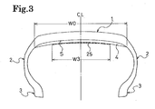
- Fig. 3 is a meridian sectional view illustrating a pneumatic tire according to still another embodiment of the present invention.
- Fig. 1 illustrates a pneumatic tire according to an embodiment of the present invention.
- reference numeral 1 denotes a tread portion
- reference numeral 2 denotes sidewall portions
- reference numeral 3 denotes bead portions.
- a sealant layer 4 is formed on an inner surface S of the tire in a region corresponding to the tread portion 1.
- the composition of the sealant layer 4 is not particularly limited, but the sealant layer 4 may be made of, for example, a rubber composition containing a rubber component such as polyisobutylene, polybutadiene, or isobutylene isoprene rubber.
- the rubber composition for the sealant it is favorable to use a rubber composition in which the crosslinkage of rubber component is suppressed or a rubber composition in which rubber components are decomposed by heat generated at a curing process.
- a tackifier, a softener, a filler, short fibers, and the like may be added to the rubber composition for the sealant as necessary.
- a cover sheet 5 is formed on an inner side of the sealant layer 4 in a radial direction of the tire so as to cover the sealant layer 4.
- the width of the cover sheet 5 is made larger than the width of the sealant layer 4, and portions of the cover sheet 5, which are not overlapped with the sealant layer 4, are bonded to the inner surface S of the tire. Bonding both ends of the cover sheet 5 to the inner surface S of the tire is advantageous in suppressing the flow of the sealant in the sealant layer 4.
- the cover sheet 5 may be formed of a film made of a rubber or a resin, or alternatively may be formed of a nonwoven fabric or the like.
- the mass per unit area (g/cm 2 ) of a center portion 5a is made larger than the mass per unit area (g/cm 2 ) of outer portions 5b.
- the following may be employed as means for relatively increasing the mass per unit area of the center portion 5a of the cover sheet 5.
- the specific gravity or the density of the constituent materials of the cover sheet 5 is varied according to the position, or the thickness of the cover sheet 5 is varied according to the position. In this embodiment, while the thickness of the cover sheet 5 is made substantially uniform over the entire region, the density of the constituent materials in the center portion 5a is made larger than that in the outer portions 5b.
- the mass distribution of the cover sheet 5 is relatively increased in a portion near the tread center on the basis of the mass per unit area of the cover sheet 5 as described above. This makes it possible.to suppress the flow of the sealant in the sealant layer 4 toward the tread center by utilizing a centrifugal force acting on the cover sheet 5 during the running of the tire.
- the width W1 of the center portion 5a of the cover sheet 5 is set in a range of 7% to 55%, or more preferably in a range of 25% to 55%, of the width W0 of the sealant layer 4. More specifically, the center portion 5a is arranged symmetrically on both sides of a center line CL of the tire. If the width W1 of the center portion 5a of the cover sheet 5 is out of the above-described range, an effect of selectively suppressing a portion, near the tread center, of the sealant layer 4 is reduced.
- Fig. 2 illustrates a pneumatic tire according to another embodiment of the present invention.
- the same components as those illustrated in Fig. 1 are denoted by the same reference numerals, and detailed description of the components will be omitted.
- a cover sheet 15 is formed on an inner side of a sealant layer 4 in a radial direction of the tire so as to cover the sealant layer 4.
- the width of the cover sheet 15 is made larger than the width of the sealant layer 4, and portions of the cover sheet 15, which are not overlapped with the sealant layer 4, are bonded to the inner surface S of the tire. Bonding both ends of the cover sheet 15 to the inner surface S of the tire is advantageous in suppressing the flow of the sealant in the sealant layer 4.
- the cover sheet 15 may be formed of a film made of a rubber or a resin, or alternatively formed of a nonwoven fabric or the like.
- the thickness of a center portion 15a is made larger than the thickness of outer portions 15b.
- the mass per unit area (g/cm 2 ) of the center portion 15a is larger than the mass per unit area (g/cm 2 ) of the outer portions 15b.
- the thickness of the center portion 15a of the cover sheet 15 may be uniform, or may be gradually increased toward the tread center.
- the cover sheet 15 in which the center portion 15a has a thickness different from the thickness of the outer portions 15b may be formed by being extruded to have a non-uniform thickness or by laminating a plurality of sheets.
- the mass distribution of the cover sheet 15 is relatively increased in a portion near the tread center on the basis of the thickness of the cover sheet 15 as described above.' This makes it possible to suppress the flow of the sealant in the sealant layer 4 toward the tread center by utilizing a centrifugal force acting on the cover sheet 15 during the running of the tire.
- the width W2 of the center portion 15a of the cover sheet 15 is set in a range of 7% to 55%, or more preferably in a range of 25% to 55%, of the width W0 of the sealant layer 4. More specifically, the center portion 15a is arranged symmetrically on both sides of a center line CL of the tire. If the width W2 of the center portion 15a of the cover sheet 15 is out of the above-described range, an effect of selectively suppressing a portion, near the tread center, of the sealant layer 4 is reduced.
- the thickness of the center portion 15a of the cover sheet 15 is set in a range of 130% to 250% of the thickness of the outer portions 15b. If the thickness of the center portion 15a of the cover sheet 15 is less than 130% of the thickness of the outer portions 15b, the effect of selectively suppressing a portion, near the tread center, of the sealant layer 4 is reduced. By contrast, if the thickness of the center portion 15a exceeds 250% of the thickness of the outer portions 15b, the portion, near the tread center, of the sealant layer 4 is reduced in thickness due to the centrifugal force generated during the running of the tire.
- Fig. 3 illustrates a pneumatic tire according to still another embodiment of the present invention.
- the same components as those illustrated in Fig. 1 are denoted by the same reference numerals, and detailed description of the components will be omitted.
- a cover sheet 25 is formed on an inner side of a sealant layer 4 in a radial direction of the tire.
- the width of the cover sheet 25 is made smaller than the width of the sealant layer 4.
- the cover sheet 25 may be formed of a film made of a rubber or a resin, or alternatively formed of a nonwoven fabric or the like.
- the mass distribution of the cover sheet 25 is relatively increased in a portion near the tread center by causing the cover sheet 25 to have a smaller width than that of the sealant layer 4 as described above. This makes it possible to suppress the flow of the sealant in the sealant layer 4 toward the tread center by utilizing a centrifugal force acting on the cover sheet 25 during the running of the tire.
- the width W3 of the cover sheet 25 is set in a range of 7% to 55%, or more preferably in a range of 25% to 55%, of the width W0 of the sealant layer 4. More specifically, the cover sheet 25 is arranged symmetrically on both sides of a center line CL of the tire. If the width W3 of the cover sheet 25 is out of the above-described range, an effect of selectively suppressing a portion, near the tread center, of the sealant layer 4 is reduced.
- Pneumatic tires of Conventional Example and Examples 1 to 6 were prepared each having a tire size of 195/65R15 and including a sealant layer formed on an inner surface of the tire in a region corresponding to a tread portion of the tire.
- the width W0 of the sealant layer was set at 160 mm, and a cover sheet was disposed on an inner side of the sealant layer in a radial direction of the tire while these pneumatic tires had structures of the cover sheets different from one another.
- the cover sheet was disposed on the inner side of the sealant layer in the radial direction of the tire so as to cover the sealant layer.
- the thickness of the cover sheet was set uniform at 1 mm over the entire region thereof.
- the cover sheet was disposed on the inner side of the sealant layer in the radial direction of the tire so as to cover the sealant layer.
- the thickness of a center portion of the cover sheet was set at 2 mm while the thickness of outer portions thereof was set at 1 mm.
- the tires of Examples 1 to 3 were made different from one another in the ratio (W2/W0) of the width W2 of the center portion to the width W0 of the sealant layer.
- the mass per unit area of the center portion of the cover sheet was made larger than the mass per unit area of the outer portions thereof.
- the cover sheet having a thickness of 1 mm was disposed on the inner side of the sealant layer in the radial direction of the tire.
- the width of the cover sheet was made smaller than the width of the sealant layer.
- the tires of Examples 4 to 6 were made different from one another in the ratio (W3/W0) of the width W3 of the cover sheet to the width W0 of the sealant layer.
- Example 2 Example 3
- Example 4 Example 5
- Example 6 Structure of Cover Sheet Uniform Thickness Fig. 2 Fig. 2 Fig. 2 Fig. 3 Fig. 3 W2/W0 - 0.1 0.5 0.8 - - - W3/W0 - - - - 0.1 0.5 0.8 Changed Amount of Width of Sealant Layer (mm) 25 10 7 23 10 7 23 Thickness of Sealant Layer at Center (mm) 5.5 5.0 4.5 5.0 5.0 4.5 5.0
- each of the tires of Examples 1 to 6 had a smaller changed amount of the width of the sealant layer, and also had a smaller thickness of the sealant layer at the position of the tread center after the running, than those of the tire of Conventional Example. In other words, in each of the tires of Examples 1 to 6, the flow of the sealant in the sealant layer toward the tread center due to the centrifugal force generated during the running of the tire was suppressed.
Landscapes
- Engineering & Computer Science (AREA)
- Mechanical Engineering (AREA)
- Tires In General (AREA)
Abstract
Description
- The present invention relates to a pneumatic tire provided with a sealant layer on an inner surface of the tire in a region corresponding to a tread portion of the tire, and more specifically relates to a pneumatic tire capable of suppressing a flow of a sealant in the sealant layer due to a centrifugal force generated during the running of the tire.
- There are pneumatic tires each provided with a sealant layer on an inner surface of the tire in a region corresponding to a tread portion of the tire. A sealant contained in the sealant layer is generally composed of a compound which is not crosslinked. Thus, the sealant has appropriate viscosity and fluidity for the sealing of a hole, which would be formed by a foreign substance, such as a nail, getting stuck in the tread portion.
- However, in the pneumatic tire including the sealant layer, the sealant sometimes flows toward the tread center due to a centrifugal force during the running of the tire, so that the amount of sealant is reduced near the shoulders of the tire. Such a formation of a portion where the amount of sealant is locally reduced in the sealant layer not only reduces the sealing performance, but also deteriorates the weight balance of the entire tire, possibly causing a problem in that vibrations are likely to occur.
- In view of the above-described problems, an approach has been proposed in which a sealant layer is divided into a plurality of portions with partition walls in a width direction of the tire, so that a flow of the sealant in the sealant layer in the width direction of the tire is suppressed (see, for example, Japanese patent application Kokai publication Nos.
2003-285376 2003-334868 Hei. 6-226870 - However, dividing a sealant layer into a plurality of portions with partition walls in a width direction of the tire is significantly difficult to implement in actual manufacture of tires, and accordingly has not yet been put into practice in the current situation.
- An object of the present invention is to provide a pneumatic tire capable of suppressing a flow of a sealant in the sealant layer due to a centrifugal force generated during the running of the tire.
- A pneumatic tire of the present invention for achieving the above-described object is a pneumatic tire provided with a sealant layer on an inner surface of the tire in a region corresponding to a tread portion of the tire. The pneumatic tire is characterized,by including a cover sheet disposed on an inner side of the sealant layer in a radial direction of the tire so as to cover the sealant layer, and is characterized in that a mass per unit area of a center portion of the cover sheet is made larger than a mass per unit area of outer portions of the cover sheet.
- In addition, a pneumatic tire of the present invention for achieving the above-described object is a pneumatic tire provided with a sealant layer on an inner surface of the tire in a region corresponding to a tread portion of the tire. The pneumatic tire is characterized by including a cover sheet disposed on an inner side of the sealant layer in a radial direction of the tire so as to cover the sealant layer, and is
characterized in that a thickness of a center portion of the cover sheet is made larger than a thickness of outer portions of the cover sheet. - Moreover, a pneumatic tire of the present invention for achieving the above-described object is a pneumatic tire provided with a sealant layer on an inner surface of the tire in a region corresponding to a tread portion of the tire. The pneumatic tire is characterized by including a cover sheet disposed on an inner side of the sealant layer in a radial direction of the tire, and characterized in that a width of the cover sheet is made smaller than a width of the sealant layer.
- According to the present invention, in a pneumatic tire provided with a sealant layer on an inner surface of the tire in a region corresponding to a tread portion of the tire, a cover sheet is disposed on an inner side of the sealant layer in a radial direction of the tire, and the mass distribution of the cover sheet is relatively increased in a portion near the tread center, so that the flow of a sealant in the sealant layer toward the tread center can be suppressed by utilizing a centrifugal force acting on the cover sheet during the running of the tire. This makes it possible to secure an excellent sealing performance and to avoid an occurrence of vibration based on unbalanced weight. Moreover, since the above-described advantageous effects can be obtained by only adjusting the mass distribution of the cover sheet, the present invention has high feasibility as compared with such a case where a sealant layer is divided into a plurality of portions with partition walls as in the conventional approach.
- In the case where the cover sheet is disposed on the inner side of the sealant layer in the radial direction of the tire so as to cover the sealant layer, and the mass per unit area of the center portion of the cover sheet is made larger than the mass per unit area of the outer portions of the cover sheet, it is preferable that a width of the center portion of the cover sheet be set in a range of 7% to 55% of a width of the sealant layer. This makes it possible to effectively suppress the flow of the sealant in the sealant layer.
- In the case where the cover sheet is disposed on the inner side of the sealant layer in the radial direction of the tire so as to cover the sealant layer, and the thickness of the center portion of the cover sheet is made larger than the thickness of the outer portions of the cover sheet, it is preferable that a width of the center portion of the cover sheet be set in a range of 7% to 55% of a width of the sealant layer. Particularly, it is preferable that a thickness of the center portion of the cover sheet be set in a range of 130% to 250% of a thickness of the outer portions thereof. This makes it possible to effectively suppress the flow of the sealant in the sealant layer.
- In the case where the cover sheet is disposed on the inner side of the sealant layer in the radial direction of the tire, and the width of the cover sheet is made smaller than the width of the sealant layer, it is preferable that the width of the cover sheet be set in a range of 7% to 55% of the width of the sealant layer. This makes it possible to effectively suppress the flow of the sealant in the sealant layer.
-
Fig. 1 is a meridian sectional view illustrating a pneumatic tire according to an embodiment of the present invention.
Fig. 2 is a meridian sectional view illustrating a pneumatic tire according to another embodiment of the present invention.
Fig. 3 is a meridian sectional view illustrating a pneumatic tire according to still another embodiment of the present invention. - Hereinafter, a configuration of the present invention will be described in detail with reference to the accompanying drawings.
Fig. 1 illustrates a pneumatic tire according to an embodiment of the present invention. InFig. 1 ,reference numeral 1 denotes a tread portion,reference numeral 2 denotes sidewall portions, andreference numeral 3 denotes bead portions. As illustrated inFig. 1 , asealant layer 4 is formed on an inner surface S of the tire in a region corresponding to thetread portion 1. The composition of thesealant layer 4 is not particularly limited, but thesealant layer 4 may be made of, for example, a rubber composition containing a rubber component such as polyisobutylene, polybutadiene, or isobutylene isoprene rubber. As the rubber composition for the sealant, it is favorable to use a rubber composition in which the crosslinkage of rubber component is suppressed or a rubber composition in which rubber components are decomposed by heat generated at a curing process. In addition, a tackifier, a softener, a filler, short fibers, and the like may be added to the rubber composition for the sealant as necessary. - In the pneumatic tire, a
cover sheet 5 is formed on an inner side of thesealant layer 4 in a radial direction of the tire so as to cover thesealant layer 4. The width of thecover sheet 5 is made larger than the width of thesealant layer 4, and portions of thecover sheet 5, which are not overlapped with thesealant layer 4, are bonded to the inner surface S of the tire. Bonding both ends of thecover sheet 5 to the inner surface S of the tire is advantageous in suppressing the flow of the sealant in thesealant layer 4. Thecover sheet 5 may be formed of a film made of a rubber or a resin, or alternatively may be formed of a nonwoven fabric or the like. - In the
cover sheet 5, the mass per unit area (g/cm2) of acenter portion 5a is made larger than the mass per unit area (g/cm2) ofouter portions 5b. The following may be employed as means for relatively increasing the mass per unit area of thecenter portion 5a of thecover sheet 5. Specifically, the specific gravity or the density of the constituent materials of thecover sheet 5 is varied according to the position, or the thickness of thecover sheet 5 is varied according to the position. In this embodiment, while the thickness of thecover sheet 5 is made substantially uniform over the entire region, the density of the constituent materials in thecenter portion 5a is made larger than that in theouter portions 5b. - The mass distribution of the
cover sheet 5 is relatively increased in a portion near the tread center on the basis of the mass per unit area of thecover sheet 5 as described above. This makes it possible.to suppress the flow of the sealant in thesealant layer 4 toward the tread center by utilizing a centrifugal force acting on thecover sheet 5 during the running of the tire. - In the pneumatic tire, the width W1 of the
center portion 5a of thecover sheet 5 is set in a range of 7% to 55%, or more preferably in a range of 25% to 55%, of the width W0 of thesealant layer 4. More specifically, thecenter portion 5a is arranged symmetrically on both sides of a center line CL of the tire. If the width W1 of thecenter portion 5a of thecover sheet 5 is out of the above-described range, an effect of selectively suppressing a portion, near the tread center, of thesealant layer 4 is reduced. -
Fig. 2 illustrates a pneumatic tire according to another embodiment of the present invention. InFig. 2 , the same components as those illustrated inFig. 1 are denoted by the same reference numerals, and detailed description of the components will be omitted. - As illustrated in
Fig. 2 , acover sheet 15 is formed on an inner side of asealant layer 4 in a radial direction of the tire so as to cover thesealant layer 4. The width of thecover sheet 15 is made larger than the width of thesealant layer 4, and portions of thecover sheet 15, which are not overlapped with thesealant layer 4, are bonded to the inner surface S of the tire. Bonding both ends of thecover sheet 15 to the inner surface S of the tire is advantageous in suppressing the flow of the sealant in thesealant layer 4. Thecover sheet 15 may be formed of a film made of a rubber or a resin, or alternatively formed of a nonwoven fabric or the like. - In the
cover sheet 15, the thickness of acenter portion 15a is made larger than the thickness ofouter portions 15b. As a result, in thecover sheet 15, the mass per unit area (g/cm2) of thecenter portion 15a is larger than the mass per unit area (g/cm2) of theouter portions 15b. The thickness of thecenter portion 15a of thecover sheet 15 may be uniform, or may be gradually increased toward the tread center. Thecover sheet 15 in which thecenter portion 15a has a thickness different from the thickness of theouter portions 15b may be formed by being extruded to have a non-uniform thickness or by laminating a plurality of sheets. - The mass distribution of the
cover sheet 15 is relatively increased in a portion near the tread center on the basis of the thickness of thecover sheet 15 as described above.' This makes it possible to suppress the flow of the sealant in thesealant layer 4 toward the tread center by utilizing a centrifugal force acting on thecover sheet 15 during the running of the tire. - In the pneumatic tire, the width W2 of the
center portion 15a of thecover sheet 15 is set in a range of 7% to 55%, or more preferably in a range of 25% to 55%, of the width W0 of thesealant layer 4. More specifically, thecenter portion 15a is arranged symmetrically on both sides of a center line CL of the tire. If the width W2 of thecenter portion 15a of thecover sheet 15 is out of the above-described range, an effect of selectively suppressing a portion, near the tread center, of thesealant layer 4 is reduced. - In addition, the thickness of the
center portion 15a of thecover sheet 15 is set in a range of 130% to 250% of the thickness of theouter portions 15b. If the thickness of thecenter portion 15a of thecover sheet 15 is less than 130% of the thickness of theouter portions 15b, the effect of selectively suppressing a portion, near the tread center, of thesealant layer 4 is reduced. By contrast, if the thickness of thecenter portion 15a exceeds 250% of the thickness of theouter portions 15b, the portion, near the tread center, of thesealant layer 4 is reduced in thickness due to the centrifugal force generated during the running of the tire. -
Fig. 3 illustrates a pneumatic tire according to still another embodiment of the present invention. InFig. 3 , the same components as those illustrated inFig. 1 are denoted by the same reference numerals, and detailed description of the components will be omitted. - As illustrated in
Fig. 3 , acover sheet 25 is formed on an inner side of asealant layer 4 in a radial direction of the tire. The width of thecover sheet 25 is made smaller than the width of thesealant layer 4. Thecover sheet 25 may be formed of a film made of a rubber or a resin, or alternatively formed of a nonwoven fabric or the like. - The mass distribution of the
cover sheet 25 is relatively increased in a portion near the tread center by causing thecover sheet 25 to have a smaller width than that of thesealant layer 4 as described above. This makes it possible to suppress the flow of the sealant in thesealant layer 4 toward the tread center by utilizing a centrifugal force acting on thecover sheet 25 during the running of the tire. - In the pneumatic tire, the width W3 of the
cover sheet 25 is set in a range of 7% to 55%, or more preferably in a range of 25% to 55%, of the width W0 of thesealant layer 4. More specifically, thecover sheet 25 is arranged symmetrically on both sides of a center line CL of the tire. If the width W3 of thecover sheet 25 is out of the above-described range, an effect of selectively suppressing a portion, near the tread center, of thesealant layer 4 is reduced. - Although the preferred embodiments of the present invention have been described in detail so far, it should be understood that various modifications, substitutions, and replacements may be made on the embodiments without departing from the spirit and scope of the present invention defined in the scope of the attached claims. Example
- Pneumatic tires of Conventional Example and Examples 1 to 6 were prepared each having a tire size of 195/65R15 and including a sealant layer formed on an inner surface of the tire in a region corresponding to a tread portion of the tire. In these pneumatic tires of Comparative Example and Examples 1 to 6, the width W0 of the sealant layer was set at 160 mm, and a cover sheet was disposed on an inner side of the sealant layer in a radial direction of the tire while these pneumatic tires had structures of the cover sheets different from one another.
- In the tire of Conventional Example, the cover sheet was disposed on the inner side of the sealant layer in the radial direction of the tire so as to cover the sealant layer. In addition, the thickness of the cover sheet was set uniform at 1 mm over the entire region thereof. In each of the tires of Examples 1 to 3, the cover sheet was disposed on the inner side of the sealant layer in the radial direction of the tire so as to cover the sealant layer. In addition, the thickness of a center portion of the cover sheet was set at 2 mm while the thickness of outer portions thereof was set at 1 mm. Moreover, the tires of Examples 1 to 3 were made different from one another in the ratio (W2/W0) of the width W2 of the center portion to the width W0 of the sealant layer. Furthermore, in each of the tires of Examples 1 to 3, the mass per unit area of the center portion of the cover sheet was made larger than the mass per unit area of the outer portions thereof. In each of the tires of Examples 4 to 6, the cover sheet having a thickness of 1 mm was disposed on the inner side of the sealant layer in the radial direction of the tire. In addition, the width of the cover sheet was made smaller than the width of the sealant layer. Moreover, the tires of Examples 4 to 6 were made different from one another in the ratio (W3/W0) of the width W3 of the cover sheet to the width W0 of the sealant layer.
- Each of these tires was tested by running the tire for 80 hours with an air pressure of 220 kPa at a speed of 80 km/h. After the test, the width of the sealant layer was measured to obtain a changed amount (a decreased amount) from the original width thereof before the test. Moreover, the thickness of the sealant layer at the position of the tread center was measured. The results of the measurements are shown in Table 1.
-
Table 1 Conventional Example Example 1 Example 2 Example 3 Example 4 Example 5 Example 6 Structure of Cover Sheet Uniform Thickness Fig. 2 Fig. 2 Fig. 2 Fig. 3 Fig. 3 Fig. 3 W2/W0 - 0.1 0.5 0.8 - - - W3/W0 - - - - 0.1 0.5 0.8 Changed Amount of Width of Sealant Layer (mm) 25 10 7 23 10 7 23 Thickness of Sealant Layer at Center (mm) 5.5 5.0 4.5 5.0 5.0 4.5 5.0 - As shown in Table 1, each of the tires of Examples 1 to 6 had a smaller changed amount of the width of the sealant layer, and also had a smaller thickness of the sealant layer at the position of the tread center after the running, than those of the tire of Conventional Example. In other words, in each of the tires of Examples 1 to 6, the flow of the sealant in the sealant layer toward the tread center due to the centrifugal force generated during the running of the tire was suppressed.
Claims (7)
- A pneumatic tire provided with a sealant layer on an inner surface of the tire in a region corresponding to a tread portion of the tire, the pneumatic tire comprising a cover sheet disposed on an inner side of the sealant layer in a radial direction of the tire so as to cover the sealant layer, wherein a mass per unit area of a center portion of the cover sheet is made larger than a mass per unit area of outer portions of the cover sheet.
- The pneumatic tire according to claim 1, wherein a width of the center portion of the cover sheet is set in a range of 7% to 55% of a width of the sealant layer.
- A pneumatic tire provided with a sealant layer on an inner surface of the tire in a region corresponding to a tread portion of the tire, the pneumatic tire comprising a cover sheet disposed on an inner side of the sealant layer in a radial direction of the tire so as to cover the sealant layer, wherein a thickness of a center portion of the cover sheet is made larger than a thickness of outer portions of the cover sheet.
- The pneumatic tire according to claim 3, wherein a width of the center portion of the cover sheet is set in a range of 7% to 55% of a width of the sealant layer.
- The pneumatic tire according to claim 4, wherein a thickness of the center portion of the cover sheet is set in a range of 130% to 250% of a thickness of the outer portions thereof.
- A pneumatic tire provided with a sealant layer on an inner surface of the tire in a region corresponding to a tread portion of the tire, the pneumatic tire comprising a cover sheet disposed on an inner side of the sealant layer in a radial direction of the tire, wherein a width of the cover sheet is made smaller than a width of the sealant layer.
- The pneumatic tire according to claim 6, wherein the width of the cover sheet is set in a range of 7% to 55% of the width of the sealant layer.
Applications Claiming Priority (1)
| Application Number | Priority Date | Filing Date | Title |
|---|---|---|---|
| JP2008126406A JP4569666B2 (en) | 2008-05-13 | 2008-05-13 | Pneumatic tire |
Publications (2)
| Publication Number | Publication Date |
|---|---|
| EP2119577A1 true EP2119577A1 (en) | 2009-11-18 |
| EP2119577B1 EP2119577B1 (en) | 2014-06-11 |
Family
ID=40823299
Family Applications (1)
| Application Number | Title | Priority Date | Filing Date |
|---|---|---|---|
| EP09005573.2A Not-in-force EP2119577B1 (en) | 2008-05-13 | 2009-04-21 | Pneumatic tire |
Country Status (4)
| Country | Link |
|---|---|
| US (1) | US8146634B2 (en) |
| EP (1) | EP2119577B1 (en) |
| JP (1) | JP4569666B2 (en) |
| CN (1) | CN101580000B (en) |
Cited By (1)
| Publication number | Priority date | Publication date | Assignee | Title |
|---|---|---|---|---|
| CN113147271A (en) * | 2021-06-11 | 2021-07-23 | 正新橡胶(中国)有限公司 | Pneumatic tire and puncture-preventing method thereof |
Families Citing this family (4)
| Publication number | Priority date | Publication date | Assignee | Title |
|---|---|---|---|---|
| IT1396617B1 (en) * | 2009-11-25 | 2012-12-14 | Pirelli | METHOD FOR SELF-CHECKING THE SELF-SEALING CAPACITY OF A SELF-SEALING PNEUMATIC AND TIRE FOR VEHICLE WHEELS |
| US8646501B2 (en) | 2010-11-11 | 2014-02-11 | The Goodyear Tire & Rubber Company | Puncture sealant laminate |
| JP6516329B2 (en) * | 2015-09-25 | 2019-05-22 | 住友ゴム工業株式会社 | Tire evaluation method |
| JP7620178B2 (en) * | 2020-06-19 | 2025-01-23 | 横浜ゴム株式会社 | Pneumatic tires |
Citations (9)
| Publication number | Priority date | Publication date | Assignee | Title |
|---|---|---|---|---|
| AU473985B2 (en) * | 1974-05-21 | 1975-11-27 | General Tire And Rubber Company | Improved puncture sealing means for pneumatic tires |
| US4895610A (en) * | 1983-08-15 | 1990-01-23 | The Goodyear Tire & Rubber Company | Self-sealing pneumatic tire and method of manufacturing the same |
| JPH06226870A (en) | 1993-02-02 | 1994-08-16 | Bridgestone Corp | Pneumatic tire |
| JP2003285376A (en) | 2002-03-28 | 2003-10-07 | Yokohama Rubber Co Ltd:The | Manufacturing method of self-sealing tire |
| JP2003334868A (en) | 2002-05-20 | 2003-11-25 | Yokohama Rubber Co Ltd:The | Manufacturing method of self-sealing tire |
| EP1424222A1 (en) * | 2001-09-04 | 2004-06-02 | The Yokohama Rubber Co., Ltd. | Pneumatic tire and method of producing the same |
| EP1433830A1 (en) * | 2001-09-26 | 2004-06-30 | The Yokohama Rubber Co., Ltd. | RUBBER COMPOSITION FOR PUNCTURE−PREVENTIVE SEALANT, PNEUMATIC TIRE HAVING TACKY SEALANT LAYER, AND PROCESS FOR PRODUCING THE SAME |
| EP1580232A1 (en) * | 2004-03-17 | 2005-09-28 | The Goodyear Tire & Rubber Company | Pneumatic tire having built-in colored sealant layer and preparation thereof |
| EP1859967A1 (en) | 2005-03-11 | 2007-11-28 | The Yokohama Rubber Co., Ltd. | Pneumatic tire and process for producing the same |
Family Cites Families (12)
| Publication number | Priority date | Publication date | Assignee | Title |
|---|---|---|---|---|
| US3048509A (en) * | 1959-12-22 | 1962-08-07 | Gen Tire & Rubber Co | Puncture sealing means for pneumatic tires |
| GB1190766A (en) * | 1966-08-10 | 1970-05-06 | Dunlop Company Ltd Formerly Du | Improvements in and relating to Pneumatic Tyres |
| CA987211A (en) * | 1973-05-03 | 1976-04-13 | Roy J. Emerson | Puncture sealing means for pneumatic tires |
| JPS53142706A (en) * | 1977-05-16 | 1978-12-12 | Suteji Komuro | Apparatus for preventing puncture of tire |
| JPS583845B2 (en) * | 1977-08-04 | 1983-01-24 | 株式会社ブリヂストン | Safety tire with dual puncture seal layer |
| JPS61229604A (en) * | 1985-04-02 | 1986-10-13 | Bridgestone Corp | Pneumatic tubeless tire having burst preventing function |
| US5824170A (en) * | 1993-09-10 | 1998-10-20 | Michelin Recherche Et Technique S.A. | Tire with a profiled innerliner |
| DE60225460T2 (en) * | 2001-09-14 | 2009-02-26 | Honda Giken Kogyo K.K. | A pneumatic tire having a sealant layer and method of making the same |
| JP3996796B2 (en) * | 2002-03-25 | 2007-10-24 | 本田技研工業株式会社 | Tubeless tire |
| JP2006152110A (en) * | 2004-11-29 | 2006-06-15 | Yokohama Rubber Co Ltd:The | Anti-puncture sealant composition and pneumatic tire |
| JP2007253805A (en) * | 2006-03-23 | 2007-10-04 | Honda Motor Co Ltd | Pneumatic tire |
| US20080142140A1 (en) * | 2006-12-15 | 2008-06-19 | Patrick David Marks | Method and apparatus for building a puncture sealant tire |
-
2008
- 2008-05-13 JP JP2008126406A patent/JP4569666B2/en not_active Expired - Fee Related
-
2009
- 2009-04-07 US US12/419,808 patent/US8146634B2/en not_active Expired - Fee Related
- 2009-04-21 EP EP09005573.2A patent/EP2119577B1/en not_active Not-in-force
- 2009-05-12 CN CN2009101408248A patent/CN101580000B/en not_active Expired - Fee Related
Patent Citations (9)
| Publication number | Priority date | Publication date | Assignee | Title |
|---|---|---|---|---|
| AU473985B2 (en) * | 1974-05-21 | 1975-11-27 | General Tire And Rubber Company | Improved puncture sealing means for pneumatic tires |
| US4895610A (en) * | 1983-08-15 | 1990-01-23 | The Goodyear Tire & Rubber Company | Self-sealing pneumatic tire and method of manufacturing the same |
| JPH06226870A (en) | 1993-02-02 | 1994-08-16 | Bridgestone Corp | Pneumatic tire |
| EP1424222A1 (en) * | 2001-09-04 | 2004-06-02 | The Yokohama Rubber Co., Ltd. | Pneumatic tire and method of producing the same |
| EP1433830A1 (en) * | 2001-09-26 | 2004-06-30 | The Yokohama Rubber Co., Ltd. | RUBBER COMPOSITION FOR PUNCTURE−PREVENTIVE SEALANT, PNEUMATIC TIRE HAVING TACKY SEALANT LAYER, AND PROCESS FOR PRODUCING THE SAME |
| JP2003285376A (en) | 2002-03-28 | 2003-10-07 | Yokohama Rubber Co Ltd:The | Manufacturing method of self-sealing tire |
| JP2003334868A (en) | 2002-05-20 | 2003-11-25 | Yokohama Rubber Co Ltd:The | Manufacturing method of self-sealing tire |
| EP1580232A1 (en) * | 2004-03-17 | 2005-09-28 | The Goodyear Tire & Rubber Company | Pneumatic tire having built-in colored sealant layer and preparation thereof |
| EP1859967A1 (en) | 2005-03-11 | 2007-11-28 | The Yokohama Rubber Co., Ltd. | Pneumatic tire and process for producing the same |
Cited By (1)
| Publication number | Priority date | Publication date | Assignee | Title |
|---|---|---|---|---|
| CN113147271A (en) * | 2021-06-11 | 2021-07-23 | 正新橡胶(中国)有限公司 | Pneumatic tire and puncture-preventing method thereof |
Also Published As
| Publication number | Publication date |
|---|---|
| CN101580000A (en) | 2009-11-18 |
| US8146634B2 (en) | 2012-04-03 |
| US20090283192A1 (en) | 2009-11-19 |
| JP2009274530A (en) | 2009-11-26 |
| JP4569666B2 (en) | 2010-10-27 |
| EP2119577B1 (en) | 2014-06-11 |
| CN101580000B (en) | 2011-04-20 |
Similar Documents
| Publication | Publication Date | Title |
|---|---|---|
| EP3093165B1 (en) | Sealant tire and method for producing the sealant tire | |
| CN101588930B (en) | Pneumatic tire and method of producing the same | |
| EP1510366B1 (en) | Assembly of pneumatic tire and rim, sound suppressing body used for the assembly, and pneumatic tire storage method | |
| EP3199372B1 (en) | Pneumatic tire and method for producing same | |
| KR102089270B1 (en) | Vehicle pneumatic tire | |
| EP2119577B1 (en) | Pneumatic tire | |
| JP6519472B2 (en) | Pneumatic tire | |
| CN1669835A (en) | Pneumatic tire with noise reducer | |
| CN106255603A (en) | Tire including noise reduction foam strips | |
| US20100084067A1 (en) | Pneumatic tire | |
| EP2596933B1 (en) | Pneumatic tire and process for production thereof, and tire curing bladder | |
| EP3663102B1 (en) | Pneumatic tire | |
| CN103370187A (en) | Rubber patch for repairing radial tires, method for repairing radial tires using same, and repaired radial tire | |
| JP2009190448A (en) | Tire | |
| JP6155084B2 (en) | Pneumatic radial tire for passenger cars | |
| WO2019050030A1 (en) | Pneumatic tire and method for producing same | |
| WO2022171162A1 (en) | Tire with intrinsic sealant containing intrinsic cellular innermost layer | |
| EP3895912B1 (en) | Pneumatic tire | |
| WO2019050029A1 (en) | Pneumatic tire and method for producing same | |
| JP3667017B2 (en) | Pneumatic tire | |
| JP2014213838A (en) | Pneumatic radial tire for passenger car | |
| WO2007010755A1 (en) | Pedestal for mounting electronic part and tire with pedestal | |
| JP2023097897A (en) | pneumatic tire | |
| EP4206000B1 (en) | Pneumatic tire | |
| EP4227119A1 (en) | Tyre cavity resonance noise absorber |
Legal Events
| Date | Code | Title | Description |
|---|---|---|---|
| PUAI | Public reference made under article 153(3) epc to a published international application that has entered the european phase |
Free format text: ORIGINAL CODE: 0009012 |
|
| AK | Designated contracting states |
Kind code of ref document: A1 Designated state(s): AT BE BG CH CY CZ DE DK EE ES FI FR GB GR HR HU IE IS IT LI LT LU LV MC MK MT NL NO PL PT RO SE SI SK TR |
|
| 17P | Request for examination filed |
Effective date: 20091228 |
|
| 17Q | First examination report despatched |
Effective date: 20110708 |
|
| GRAP | Despatch of communication of intention to grant a patent |
Free format text: ORIGINAL CODE: EPIDOSNIGR1 |
|
| INTG | Intention to grant announced |
Effective date: 20140124 |
|
| GRAS | Grant fee paid |
Free format text: ORIGINAL CODE: EPIDOSNIGR3 |
|
| GRAA | (expected) grant |
Free format text: ORIGINAL CODE: 0009210 |
|
| RIN1 | Information on inventor provided before grant (corrected) |
Inventor name: SEKIGUCHI, TAKUMI |
|
| AK | Designated contracting states |
Kind code of ref document: B1 Designated state(s): AT BE BG CH CY CZ DE DK EE ES FI FR GB GR HR HU IE IS IT LI LT LU LV MC MK MT NL NO PL PT RO SE SI SK TR |
|
| REG | Reference to a national code |
Ref country code: GB Ref legal event code: FG4D |
|
| REG | Reference to a national code |
Ref country code: CH Ref legal event code: EP |
|
| REG | Reference to a national code |
Ref country code: IE Ref legal event code: FG4D |
|
| REG | Reference to a national code |
Ref country code: AT Ref legal event code: REF Ref document number: 672066 Country of ref document: AT Kind code of ref document: T Effective date: 20140715 |
|
| REG | Reference to a national code |
Ref country code: DE Ref legal event code: R096 Ref document number: 602009024553 Country of ref document: DE Effective date: 20140724 |
|
| PG25 | Lapsed in a contracting state [announced via postgrant information from national office to epo] |
Ref country code: GR Free format text: LAPSE BECAUSE OF FAILURE TO SUBMIT A TRANSLATION OF THE DESCRIPTION OR TO PAY THE FEE WITHIN THE PRESCRIBED TIME-LIMIT Effective date: 20140912 Ref country code: FI Free format text: LAPSE BECAUSE OF FAILURE TO SUBMIT A TRANSLATION OF THE DESCRIPTION OR TO PAY THE FEE WITHIN THE PRESCRIBED TIME-LIMIT Effective date: 20140611 Ref country code: NO Free format text: LAPSE BECAUSE OF FAILURE TO SUBMIT A TRANSLATION OF THE DESCRIPTION OR TO PAY THE FEE WITHIN THE PRESCRIBED TIME-LIMIT Effective date: 20140911 Ref country code: LT Free format text: LAPSE BECAUSE OF FAILURE TO SUBMIT A TRANSLATION OF THE DESCRIPTION OR TO PAY THE FEE WITHIN THE PRESCRIBED TIME-LIMIT Effective date: 20140611 |
|
| REG | Reference to a national code |
Ref country code: NL Ref legal event code: VDEP Effective date: 20140611 |
|
| REG | Reference to a national code |
Ref country code: AT Ref legal event code: MK05 Ref document number: 672066 Country of ref document: AT Kind code of ref document: T Effective date: 20140611 |
|
| REG | Reference to a national code |
Ref country code: LT Ref legal event code: MG4D |
|
| PG25 | Lapsed in a contracting state [announced via postgrant information from national office to epo] |
Ref country code: HR Free format text: LAPSE BECAUSE OF FAILURE TO SUBMIT A TRANSLATION OF THE DESCRIPTION OR TO PAY THE FEE WITHIN THE PRESCRIBED TIME-LIMIT Effective date: 20140611 Ref country code: LV Free format text: LAPSE BECAUSE OF FAILURE TO SUBMIT A TRANSLATION OF THE DESCRIPTION OR TO PAY THE FEE WITHIN THE PRESCRIBED TIME-LIMIT Effective date: 20140611 Ref country code: SE Free format text: LAPSE BECAUSE OF FAILURE TO SUBMIT A TRANSLATION OF THE DESCRIPTION OR TO PAY THE FEE WITHIN THE PRESCRIBED TIME-LIMIT Effective date: 20140611 |
|
| PG25 | Lapsed in a contracting state [announced via postgrant information from national office to epo] |
Ref country code: EE Free format text: LAPSE BECAUSE OF FAILURE TO SUBMIT A TRANSLATION OF THE DESCRIPTION OR TO PAY THE FEE WITHIN THE PRESCRIBED TIME-LIMIT Effective date: 20140611 Ref country code: CZ Free format text: LAPSE BECAUSE OF FAILURE TO SUBMIT A TRANSLATION OF THE DESCRIPTION OR TO PAY THE FEE WITHIN THE PRESCRIBED TIME-LIMIT Effective date: 20140611 Ref country code: PT Free format text: LAPSE BECAUSE OF FAILURE TO SUBMIT A TRANSLATION OF THE DESCRIPTION OR TO PAY THE FEE WITHIN THE PRESCRIBED TIME-LIMIT Effective date: 20141013 Ref country code: ES Free format text: LAPSE BECAUSE OF FAILURE TO SUBMIT A TRANSLATION OF THE DESCRIPTION OR TO PAY THE FEE WITHIN THE PRESCRIBED TIME-LIMIT Effective date: 20140611 Ref country code: SK Free format text: LAPSE BECAUSE OF FAILURE TO SUBMIT A TRANSLATION OF THE DESCRIPTION OR TO PAY THE FEE WITHIN THE PRESCRIBED TIME-LIMIT Effective date: 20140611 Ref country code: RO Free format text: LAPSE BECAUSE OF FAILURE TO SUBMIT A TRANSLATION OF THE DESCRIPTION OR TO PAY THE FEE WITHIN THE PRESCRIBED TIME-LIMIT Effective date: 20140611 |
|
| PG25 | Lapsed in a contracting state [announced via postgrant information from national office to epo] |
Ref country code: NL Free format text: LAPSE BECAUSE OF FAILURE TO SUBMIT A TRANSLATION OF THE DESCRIPTION OR TO PAY THE FEE WITHIN THE PRESCRIBED TIME-LIMIT Effective date: 20140611 Ref country code: IS Free format text: LAPSE BECAUSE OF FAILURE TO SUBMIT A TRANSLATION OF THE DESCRIPTION OR TO PAY THE FEE WITHIN THE PRESCRIBED TIME-LIMIT Effective date: 20141011 Ref country code: AT Free format text: LAPSE BECAUSE OF FAILURE TO SUBMIT A TRANSLATION OF THE DESCRIPTION OR TO PAY THE FEE WITHIN THE PRESCRIBED TIME-LIMIT Effective date: 20140611 Ref country code: PL Free format text: LAPSE BECAUSE OF FAILURE TO SUBMIT A TRANSLATION OF THE DESCRIPTION OR TO PAY THE FEE WITHIN THE PRESCRIBED TIME-LIMIT Effective date: 20140611 |
|
| REG | Reference to a national code |
Ref country code: DE Ref legal event code: R097 Ref document number: 602009024553 Country of ref document: DE |
|
| PLBE | No opposition filed within time limit |
Free format text: ORIGINAL CODE: 0009261 |
|
| STAA | Information on the status of an ep patent application or granted ep patent |
Free format text: STATUS: NO OPPOSITION FILED WITHIN TIME LIMIT |
|
| PG25 | Lapsed in a contracting state [announced via postgrant information from national office to epo] |
Ref country code: IT Free format text: LAPSE BECAUSE OF FAILURE TO SUBMIT A TRANSLATION OF THE DESCRIPTION OR TO PAY THE FEE WITHIN THE PRESCRIBED TIME-LIMIT Effective date: 20140611 Ref country code: DK Free format text: LAPSE BECAUSE OF FAILURE TO SUBMIT A TRANSLATION OF THE DESCRIPTION OR TO PAY THE FEE WITHIN THE PRESCRIBED TIME-LIMIT Effective date: 20140611 |
|
| 26N | No opposition filed |
Effective date: 20150312 |
|
| REG | Reference to a national code |
Ref country code: DE Ref legal event code: R097 Ref document number: 602009024553 Country of ref document: DE Effective date: 20150312 |
|
| PG25 | Lapsed in a contracting state [announced via postgrant information from national office to epo] |
Ref country code: BE Free format text: LAPSE BECAUSE OF FAILURE TO SUBMIT A TRANSLATION OF THE DESCRIPTION OR TO PAY THE FEE WITHIN THE PRESCRIBED TIME-LIMIT Effective date: 20140611 |
|
| PG25 | Lapsed in a contracting state [announced via postgrant information from national office to epo] |
Ref country code: SI Free format text: LAPSE BECAUSE OF FAILURE TO SUBMIT A TRANSLATION OF THE DESCRIPTION OR TO PAY THE FEE WITHIN THE PRESCRIBED TIME-LIMIT Effective date: 20140611 |
|
| PG25 | Lapsed in a contracting state [announced via postgrant information from national office to epo] |
Ref country code: MC Free format text: LAPSE BECAUSE OF FAILURE TO SUBMIT A TRANSLATION OF THE DESCRIPTION OR TO PAY THE FEE WITHIN THE PRESCRIBED TIME-LIMIT Effective date: 20140611 Ref country code: LU Free format text: LAPSE BECAUSE OF FAILURE TO SUBMIT A TRANSLATION OF THE DESCRIPTION OR TO PAY THE FEE WITHIN THE PRESCRIBED TIME-LIMIT Effective date: 20150421 |
|
| REG | Reference to a national code |
Ref country code: CH Ref legal event code: PL |
|
| GBPC | Gb: european patent ceased through non-payment of renewal fee |
Effective date: 20150421 |
|
| REG | Reference to a national code |
Ref country code: IE Ref legal event code: MM4A |
|
| PG25 | Lapsed in a contracting state [announced via postgrant information from national office to epo] |
Ref country code: GB Free format text: LAPSE BECAUSE OF NON-PAYMENT OF DUE FEES Effective date: 20150421 Ref country code: LI Free format text: LAPSE BECAUSE OF NON-PAYMENT OF DUE FEES Effective date: 20150430 Ref country code: CH Free format text: LAPSE BECAUSE OF NON-PAYMENT OF DUE FEES Effective date: 20150430 |
|
| REG | Reference to a national code |
Ref country code: FR Ref legal event code: ST Effective date: 20151231 |
|
| PG25 | Lapsed in a contracting state [announced via postgrant information from national office to epo] |
Ref country code: FR Free format text: LAPSE BECAUSE OF NON-PAYMENT OF DUE FEES Effective date: 20150430 |
|
| PG25 | Lapsed in a contracting state [announced via postgrant information from national office to epo] |
Ref country code: IE Free format text: LAPSE BECAUSE OF NON-PAYMENT OF DUE FEES Effective date: 20150421 |
|
| PG25 | Lapsed in a contracting state [announced via postgrant information from national office to epo] |
Ref country code: MT Free format text: LAPSE BECAUSE OF FAILURE TO SUBMIT A TRANSLATION OF THE DESCRIPTION OR TO PAY THE FEE WITHIN THE PRESCRIBED TIME-LIMIT Effective date: 20140611 |
|
| PG25 | Lapsed in a contracting state [announced via postgrant information from national office to epo] |
Ref country code: BG Free format text: LAPSE BECAUSE OF FAILURE TO SUBMIT A TRANSLATION OF THE DESCRIPTION OR TO PAY THE FEE WITHIN THE PRESCRIBED TIME-LIMIT Effective date: 20140611 Ref country code: HU Free format text: LAPSE BECAUSE OF FAILURE TO SUBMIT A TRANSLATION OF THE DESCRIPTION OR TO PAY THE FEE WITHIN THE PRESCRIBED TIME-LIMIT; INVALID AB INITIO Effective date: 20090421 |
|
| PG25 | Lapsed in a contracting state [announced via postgrant information from national office to epo] |
Ref country code: CY Free format text: LAPSE BECAUSE OF FAILURE TO SUBMIT A TRANSLATION OF THE DESCRIPTION OR TO PAY THE FEE WITHIN THE PRESCRIBED TIME-LIMIT Effective date: 20140611 |
|
| PG25 | Lapsed in a contracting state [announced via postgrant information from national office to epo] |
Ref country code: TR Free format text: LAPSE BECAUSE OF FAILURE TO SUBMIT A TRANSLATION OF THE DESCRIPTION OR TO PAY THE FEE WITHIN THE PRESCRIBED TIME-LIMIT Effective date: 20140611 |
|
| PG25 | Lapsed in a contracting state [announced via postgrant information from national office to epo] |
Ref country code: MK Free format text: LAPSE BECAUSE OF FAILURE TO SUBMIT A TRANSLATION OF THE DESCRIPTION OR TO PAY THE FEE WITHIN THE PRESCRIBED TIME-LIMIT Effective date: 20140611 |
|
| PGFP | Annual fee paid to national office [announced via postgrant information from national office to epo] |
Ref country code: DE Payment date: 20180410 Year of fee payment: 10 |
|
| REG | Reference to a national code |
Ref country code: DE Ref legal event code: R119 Ref document number: 602009024553 Country of ref document: DE |
|
| PG25 | Lapsed in a contracting state [announced via postgrant information from national office to epo] |
Ref country code: DE Free format text: LAPSE BECAUSE OF NON-PAYMENT OF DUE FEES Effective date: 20191101 |