EP2118940B1 - Apparatus for continuous fabricating superconducting tapes - Google Patents
Apparatus for continuous fabricating superconducting tapes Download PDFInfo
- Publication number
- EP2118940B1 EP2118940B1 EP08723365A EP08723365A EP2118940B1 EP 2118940 B1 EP2118940 B1 EP 2118940B1 EP 08723365 A EP08723365 A EP 08723365A EP 08723365 A EP08723365 A EP 08723365A EP 2118940 B1 EP2118940 B1 EP 2118940B1
- Authority
- EP
- European Patent Office
- Prior art keywords
- superconducting tape
- cylindrical drum
- superconducting
- reel
- tape
- Prior art date
- Legal status (The legal status is an assumption and is not a legal conclusion. Google has not performed a legal analysis and makes no representation as to the accuracy of the status listed.)
- Active
Links
Images

Classifications
-
- C—CHEMISTRY; METALLURGY
- C23—COATING METALLIC MATERIAL; COATING MATERIAL WITH METALLIC MATERIAL; CHEMICAL SURFACE TREATMENT; DIFFUSION TREATMENT OF METALLIC MATERIAL; COATING BY VACUUM EVAPORATION, BY SPUTTERING, BY ION IMPLANTATION OR BY CHEMICAL VAPOUR DEPOSITION, IN GENERAL; INHIBITING CORROSION OF METALLIC MATERIAL OR INCRUSTATION IN GENERAL
- C23C—COATING METALLIC MATERIAL; COATING MATERIAL WITH METALLIC MATERIAL; SURFACE TREATMENT OF METALLIC MATERIAL BY DIFFUSION INTO THE SURFACE, BY CHEMICAL CONVERSION OR SUBSTITUTION; COATING BY VACUUM EVAPORATION, BY SPUTTERING, BY ION IMPLANTATION OR BY CHEMICAL VAPOUR DEPOSITION, IN GENERAL
- C23C14/00—Coating by vacuum evaporation, by sputtering or by ion implantation of the coating forming material
- C23C14/22—Coating by vacuum evaporation, by sputtering or by ion implantation of the coating forming material characterised by the process of coating
- C23C14/56—Apparatus specially adapted for continuous coating; Arrangements for maintaining the vacuum, e.g. vacuum locks
- C23C14/562—Apparatus specially adapted for continuous coating; Arrangements for maintaining the vacuum, e.g. vacuum locks for coating elongated substrates
-
- H—ELECTRICITY
- H01—ELECTRIC ELEMENTS
- H01B—CABLES; CONDUCTORS; INSULATORS; SELECTION OF MATERIALS FOR THEIR CONDUCTIVE, INSULATING OR DIELECTRIC PROPERTIES
- H01B13/00—Apparatus or processes specially adapted for manufacturing conductors or cables
-
- H—ELECTRICITY
- H10—SEMICONDUCTOR DEVICES; ELECTRIC SOLID-STATE DEVICES NOT OTHERWISE PROVIDED FOR
- H10N—ELECTRIC SOLID-STATE DEVICES NOT OTHERWISE PROVIDED FOR
- H10N60/00—Superconducting devices
- H10N60/01—Manufacture or treatment
-
- H—ELECTRICITY
- H10—SEMICONDUCTOR DEVICES; ELECTRIC SOLID-STATE DEVICES NOT OTHERWISE PROVIDED FOR
- H10N—ELECTRIC SOLID-STATE DEVICES NOT OTHERWISE PROVIDED FOR
- H10N60/00—Superconducting devices
- H10N60/01—Manufacture or treatment
- H10N60/0268—Manufacture or treatment of devices comprising copper oxide
- H10N60/0296—Processes for depositing or forming copper oxide superconductor layers
- H10N60/0381—Processes for depositing or forming copper oxide superconductor layers by evaporation, e.g. MBE
Definitions
- the lower main chamber supplies raw materials such as samarium (Sm), barium (Ba), and copper (Cu) to the rotating substrate tape in the form of atomic vapor to form a high-temperature superconductor layer on the rotating substrate tape.
- raw materials such as samarium (Sm), barium (Ba), and copper (Cu)
- the substrate tape is being rotated between an evaporation region and a reaction region in the auxiliary chamber, the high- temperature superconductor layer is grown on the substrate tape.
- a material may be disposed on a portion of the outer surface of the cylindrical drum between the endless track belt and another endless track belt so as to keep the portion of the outer surface of the cylindrical drum at the same surface temperature level as the endless track belt.
- FIG. 2 is an enlarged view of portion A of FIG. 1 , according to an embodiment of the present invention.
- the superconducting tape 106 on which a super-conducting material will be deposited is released from the release reel 104a disposed at the left side of the cylindrical drum 102.
- the superconducting tape 106 is released from an inner region of the release reel 104a and is wound around an inner region of the winding reel 104b. That is, after a superconducting material is deposited on the superconducting tape 106, the superconducting tape 106 can be collected by winding the superconducting tape 106 around the inner region of the winding reel 104b.
- the winding reel 104b is disposed at the right side of the cylindrical drum 102.
- the transfer unit includes an endless track belt 108 and belt reels 110.
- the endless track belt 108 includes grooves (H) (refer to FIG. 2 ) for receiving the superconducting tape 106.
- the belt reels 110 rotate the endless track belt 108 such that a portion of the endless track belt 108 disposed outside the cylindrical drum 102 can be moved in the direction of arrow (a) from the release reel 104a to the winding reel 104b.
- the endless track belt 108 is disposed in a loop shape around a sidewall of the cylindrical drum 102 in parallel with the centerline of the cylindrical drum 102.
- the transfer unit can be provided in plurality.
- a plurality of transfer units may be radially and symmetrically arranged about the centerline of the cylindrical drum 102 i.e. equi-angularly disposed about the drum axis.
- the superconducting tape 106 can be stably placed and transferred on the belts 108.
- the grooves (H) of the belt 108 are arranged in predetermined intervals along the length direction of the belt 108 and are substantially perpendicular to the length direction of the belt 108.
Landscapes
- Engineering & Computer Science (AREA)
- Chemical & Material Sciences (AREA)
- Manufacturing & Machinery (AREA)
- Chemical Kinetics & Catalysis (AREA)
- Materials Engineering (AREA)
- Mechanical Engineering (AREA)
- Metallurgy (AREA)
- Organic Chemistry (AREA)
- Superconductors And Manufacturing Methods Therefor (AREA)
Abstract
Description
- The present invention disclosed herein relates to an apparatus for fabricating super-conducting tapes, and more particularly, to an apparatus for fabricating long super-conducting tapes by depositing a superconductor material on the long superconducting tape while continuously moving the long superconducting tape.
- In the application fields of superconductors, much research has been conducted all over the world for practical use of high-temperature superconductors. There are a first-generation high-temperature superconducting tape and a second-generation high-temperature superconducting tape. The first-generation high-temperature super-conducting tape can be fabricated through a powder in tube (PIT) process in which precursor powder is treated in a silver (Ag) pipe. The second-generation high-temperature superconducting tape is technically called as a coated conductor (CC). Institutes and companies of many countries have conducted research on CCs. Many fabricating methods have been developed for CCs. CCs have a more complicated multilayer structure than that of the first-generation high-temperature superconducting tape.
- It is considered that a superconducting tape will become the first practical superconductor product since the discovery of a high-temperature superconductor in 1986. A high-temperature superconducting tape can carry about one hundred times greater current per unit area substantially with no loss as compared with a copper wire. Since heat is generated in proportion to the power loss of an electric power device, the electric power device can be heated to a high temperature due to a power loss. Therefore, copper wires having a relatively large resistance are not suitable for high capacity power devices. However, high-temperature superconducting tapes can be usefully used for high capacity power devices. Niobium based low-temperature super conductors are not economical since they require expensive liquid helium due to their extremely low critical temperature. However, high-temperature superconducting tapes are economical since they require liquid nitrogen that can be easily obtained from air. Therefore, practical use of high-temperature superconducting tapes will mark a new era in large-scale energy industries. When the high-temperature superconductor was first discovered, although the high-temperature superconductor was considered to be the next generation of conductors, it was difficult to develop high-temperature super-conducting tapes. However, recent dramatic technical development makes it possible to practically use the high-temperature superconductor. For this, it is important to develop a method of rapidly fabricating superconducting tapes with low costs. There are many methods that can be practically used for fabricating superconducting tapes, such as a metal-organic deposition (MOD) method, a metal-organic chemical vapor deposition (MOCVD) method, and an evaporation using a drum in dual chamber (EDDC) method. The EDDC method is disclosed in
U.S. Patent No. 6,147,033 , filed by the applicant of the present invention, entitled " Apparatus and method for forming a film on a tape substrate." - In the EDDC method, a divided vacuum chamber is used. In detail, a drum is rotated in an upper auxiliary chamber under oxygen gas atmosphere at a pressure of about 0.7 Pa (5 mTorr). A substrate tape having a width of about 4 mm and thickness of about 0.1 mm or less is wound around the drum. The substrate tape and the drum are heated to a temperature of about 700°C and are rotated at a speed of about 1 revolution per second. A lower main chamber is kept at a pressure of about 0.0013Pa (0.01 mTorr). The lower main chamber supplies raw materials such as samarium (Sm), barium (Ba), and copper (Cu) to the rotating substrate tape in the form of atomic vapor to form a high-temperature superconductor layer on the rotating substrate tape. Here, the ratio of the raw materials (for example, Sm: Ba: Cu = 1:2:3) supplied from the main chamber is precisely maintained. While the substrate tape is being rotated between an evaporation region and a reaction region in the auxiliary chamber, the high- temperature superconductor layer is grown on the substrate tape.
- However, since the length of the substrate tape wound around the drum is limited, a long high-temperature superconducting tape cannot be fabricated through the EDDC method. Therefore, it is necessary to improve the EDDC method to fabricate a sufficiently long high-temperature superconducting tape. For example, a high-temperature superconducting tape having a sufficiently large length can be fabricated using two reels coaxially disposed at both sides of a drum by depositing a superconductor material on the high-temperature superconducting tape while releasing the high- temperature superconducting tape from one real and winding the superconducting tape around the other reel. Here, the high-temperature superconducting tape is wound around inner regions of the reels.
JP09102228
US4013539 discloses thin film deposition on a substrate wound helically over a drum, and moving the loops of the substrate by means of external belts.
The invention is the apparatus and method ofclaims 1 and 10. - Each of the grooves may include: support jaw portions configured to support both sides of the superconducting tape for preventing the superconducting tape from making contact with a bottom surface of the groove; and a reversely inclined sidewall to make the groove tapered upwardly for preventing the superconducting tape from being easily releasing from the groove.
- The support jaw portions may be sloped toward sidewalls of the groove such that the superconducting tape makes line contact with the support jaw portions.
- The transfer unit may be provided in plurality, wherein the transfer units are equi-angularly disposed about the axis of the cylindrical drum.
- The superconducting tape may be released from an inner region of the release reel and is wound around an inner region of the winding reel.
- A material may be disposed on a portion of the outer surface of the cylindrical drum between the endless track belt and another endless track belt so as to keep the portion of the outer surface of the cylindrical drum at the same surface temperature level as the endless track belt.
- The apparatus may further include a spiral block disposed at a side of the release reel for separating a portion of the superconducting tape on which the superconducting material is being deposited from the remaining portion of the superconducting tape in a stepped manner. When the superconducting tape is exposed to a deposition vapor, the spiral block may reciprocate in a stepped manner such that each turn of the superconducting tape wound around the cylindrical drum is simultaneously exposed to the deposition vapor.
-
FIG. 1 is a schematic view illustrating an apparatus for continuously fabricating super conducting tapes according to an embodiment of the present invention. -
FIG. 2 is an enlarged view of portion A ofFIG. 1 , according to an embodiment of the present invention. -
FIG. 3 is an enlarged view of a part ofFIG. 1 , according to an embodiment of the present invention. -
FIG. 4 is a side view illustrating the apparatus ofFIG. 1 in the direction of arrow b, according to an embodiment of the present invention. -
FIG. 5 is a perspective view illustrating a vapor block of the apparatus depicted inFIG. 1 according to an embodiment of the present invention. -
FIGS. 6 and7 are schematic views for explaining how the vapor block operates, according to an embodiment of the present invention. - Preferred embodiments of the present invention will be described below in more detail with reference to the accompanying drawings.
-
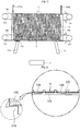
FIG. 1 is a schematic view illustrating an apparatus for continuously fabricating superconducting tapes according to an embodiment of the present invention. For clarity, arelease reel 104a and awinding reel 104b are illustrated by cutting them along a plane including the centerline and upper edge line of a hollowcylindrical drum 102. All
elements of the apparatus shown inFIG. 1 are disposed in a superconductor deposition chamber (not shown). Referring toFIG. 1 , asuperconducting tape 106 is placed on an outer surface of the hollowcylindrical drum 102, and the hollowcylindrical drum 102 is disposed in the superconductor deposition chamber for heating thesuperconducting tape 106. Thesuperconducting tape 106 on which a super-conducting material will be deposited is released from therelease reel 104a disposed at the left side of thecylindrical drum 102. Thesuperconducting tape 106 is released from an inner region of therelease reel 104a and is wound around an inner region of thewinding reel 104b. That is, after a superconducting material is deposited on thesuperconducting tape 106, thesuperconducting tape 106 can be collected by winding thesuperconducting tape 106 around the inner region of thewinding reel 104b. Thewinding reel 104b is disposed at the right side of thecylindrical drum 102. While a superconducting material is being deposited on thesuperconducting tape 106, thesuperconducting tape 106 is transferred from therelease reel 104a to thewinding reel 104b by a transfer unit. The transfer unit includes anendless track belt 108 andbelt reels 110. Theendless track belt 108 includes grooves (H) (refer toFIG. 2 ) for receiving thesuperconducting tape 106. Thebelt reels 110 rotate theendless track belt 108 such that a portion of theendless track belt 108 disposed outside thecylindrical drum 102 can be moved in the direction of arrow (a) from therelease reel 104a to the windingreel 104b. Theendless track belt 108 is disposed in a loop shape around a sidewall of thecylindrical drum 102 in parallel with the centerline of thecylindrical drum 102. The transfer unit can be provided in plurality. In this case, a plurality of transfer units may be radially and symmetrically arranged about the centerline of thecylindrical drum 102 i.e. equi-angularly disposed about the drum axis. Thus, owing to the symmetrically arranged transfer units, thesuperconducting tape 106 can be stably placed and transferred on thebelts 108. The grooves (H) of thebelt 108 are arranged in predetermined intervals along the length direction of thebelt 108 and are substantially perpendicular to the length direction of thebelt 108. When thesuperconducting tape 106 is transferred on thebelt 108, thesuperconducting tape 106 is disposed in the grooves (H). During a superconductor material deposition process, thebelt 108 is moved along an outer surface of thecylindrical drum 102 in parallel with the centerline of thecylindrical drum 102 in the direction of arrow (a) with thesuperconducting tape 106 being placed thereon. Then, thesuperconducting tape 106 is separated from thebelt 108, and thebelt 108 is moved through thecylindrical drum 102 in the direction of arrow (b). Therefore, thesuperconducting tape 106 can be continuously fed to thecylindrical drum 102. Thebelt reels 110 need to be rotated at the same speed to continuously transfer thesuperconducting tape 106 on thebelts 108. - In
FIG. 1 ,reference numeral 112 denotes a boat in which high-temperature superconducting materials are contained, andreference numeral 114 denotes chamber barrier walls for dividing the superconductor deposition chamber into an evaporation region and a reaction region.Reference numeral 116 denotes a block. The evaporation region may be an upper region of theboat 112 where the high-temperature superconducting materials evaporate from theboat 112. In the reaction region, the evaporated superconducting materials react with each other. The reaction region may be a region where the superconducting tape is placed. A deposition region (D) is a region where the evaporated superconducting materials may be deposited on the super-conducting tape. -
FIG. 2 is an enlarged view of portion A ofFIG. 1 , according to an embodiment of the present invention.FIG. 2 shows a cross-sectional view of portion A ofFIG. 1 taken along a plane including the centerline and upper edge line of thecylindrical drum 102. Referring toFIG. 2 , the grooves (H) are formed in thebelt 108 at predetermined intervals and are substantially perpendicular to the length direction of thebelt 108. Therefore, when thesuperconducting tape 106 is wound around thecylindrical drum 102, thesuperconducting tape 106 can be stably disposed in the grooves (H) of thebelt 108. In detail,support jaw portions 210 are formed in each of the grooves (H) to support both sides of thesuperconducting tape 106 such that thesuperconducting tape 106 can be spaced a predetermined distance apart from the bottom of the groove (H). That is, thesuperconducting tape 106 is not in contact with the bottom surfaces of the grooves (H). In addition, thesupport jaw portions 210 are sloped down towardsidewalls 220 of the groove (H) such that thesuperconducting tape 106 can make line contact with thesupport jaw portions 210. Owing to thesupport jaw portions 210, the contact area between thesuperconducting tape 106 and thebelt 108 can be minimized, and thus thesuperconducting tape 106 can be less damaged or contaminated by the contact with thebelt 108.Sidewalls 220 of the grooves (H) are reversely inclined. That is, the grooves (H) are tapered upwardly. Therefore, thesuperconducting tape 106 is not freely released from the grooves (H). - The width of the grooves (H) may be smaller than that of the
superconducting tape 106. In this case, additional mechanism may be necessary to stably insert thesuper-conducting tape 106 into the groove (H) after thesuperconducting tape 106 is released from therelease reel 104a. For example, referring toFIG. 3 , thesuperconducting tape 106 may be inserted into the groove (H) at a twisted angle. For this, the centerline of therelease reel 104a may have an angle with thebelt 108. Alternatively, an additional support unit may be disposed between therelease reel 104a and thebelt 108 to support a bottom surface of thesuperconducting tape 106 at an oblique angle with thebelt 108. Alternatively, thebelt 108 may be bent to widen the groove (H) in the vicinity of therelease reel 104a. To allow thesuperconducting tape 106 is stably released from the groove (H) and then be wound around the windingreel 104b, the same mechanism may be used. - The
belt 108 may be formed of a material having the same thermal expansion coefficient as thesuperconducting tape 106. For example, thebelt 108 may be formed of a hast alloy. Thebelt 108 is thin at about 3 mm so that thebelt 108 can be easily bent and wound around thebelt reels 110. -
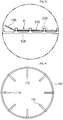
FIG. 4 is a side view illustrating the apparatus ofFIG. 1 in the direction of arrow b ofFIG. 1 , according to an embodiment of the present invention. InFIG. 4 , a super-conducting tape is not shown for clarity. A plurality of transfer units are radially arranged about the centerline of acylindrical drum 102 and are symmetric with respect to the centerline of thecylindrical drum 102. Referring toFIG. 4 , a plurality ofbelt reels 110 are arranged at an angle of 45° to each other. If the superconducting tape (not shown inFIG. 4 ) is too tightly wound around belts (not shown) of the transfer units, portions of the superconducting tape that are not supported by the belts can be in contact with thecylindrical drum 102. In this case, a superconducting material can be non-uniformly deposited on the superconducting tape since the superconducting tape has contact portions and non-contact portions with thecylindrical drum 102. To prevent such non-uniform deposition of a superconducting material, the super-conducting tape can be loosely wound around the belts of the transfer units. - Referring again to
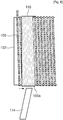
FIG. 1 , in the apparatus of the present invention, the super-conducting tape is fed into the deposition region (D) by the operation of the belt reels and the winding reel. Here, a portion of the superconducting tape placed in the deposition region (D) may be coated with a superconducting material by deposition, and the remaining portion of the superconducting tape may be not coated with the superconducting material. That is, the superconducting tape may not be simultaneously exposed to the superconducting material. In this case, it needs to minimize the boundary between the portion of the superconducting tape on which the super-conducting material is deposited and the remaining portion of the superconducting tape on which the superconducting material is not deposited so as to improve characteristics of a superconductor layer to be formed on the superconducting tape. For this reason, theblock 116 may be disposed in the vicinity of therelease reel 104a. Theblock 116 may have a flat shape having a width corresponding to the drum. Alternatively, theblock 116 may have a spiral edge corresponding to the superconducting tape wound around the drum as shown inFIG. 5 . In this case, the spiral edge of theblock 116 may have a discontinuous portion corresponding to the width of the superconducting tape. The discontinuous portion of the spiral edge of theblock 116 may be disposed at a side opposite to the deposition region. - The
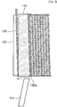
block 116 operates as follows. Theblock 116 is reciprocated in a stepped manner. Here, one step corresponds to the width of the superconducting tape. Referring toFIG. 6 , oneturn 106a of thesuperconducting tape 106 covered with theblock 116 is moved forward into the deposition region (D) together with theblock 116. Referring toFIG. 7 , only theblock 116 is moved back by one step so as to simultaneously expose the oneturn 106a of thesuperconducting tape 106 to the atmosphere of the deposition region (D). - An exemplary structure and operation of an apparatus for continuously fabricating superconducting tapes will now be described according to an embodiment of the present invention. In general, since a superconducting tape is formed of a hast alloy capable of maintaining its strength at a high-temperature, the superconducting tape can be stably held in grooves of belts. The belts are also formed of a hast alloy. The super-conducting tape is inserted in the grooves of the belts at a somewhat low tension level by considering different temperature-dependent expansion rates of a cylindrical drum and the superconducting tape so as to prevent the superconducting tape from being in contact with the cylindrical drum. As explained above, portions of the superconducting tape inserted in the grooves of the belts do not make contact with bottom surfaces of the grooves, and the grooves of the belts are tapered upwardly to prevent the super-conducting tape from being released from the grooves. The belts are continuously moved along the centerline of the cylindrical drum such that superconducting tape spirally wound around the drum can be moved from a release reel to a winding reel. For example, the superconducting tape, the release reel, the winding reel, the plurality of belts, and the cylindrical drum can be rotated once per second. The cylindrical drum, the superconducting tape wound around the cylindrical drum, the release reel feeding the superconducting tape, the winding reel collecting the superconducting tape, the belts (endless track belts), and belt reels rotating the endless belts are rapidly rotated in association with each other, and while these components are being rotated, a superconducting material is deposited on the superconducting tape. A method or mechanism for connecting such components can be easily determined based on structural parameters of the components such as lengths and diameters of the components. As the belts are moved, the superconducting tape spirally wound around the belts is moved along the centerline of the cylindrical drum, and the release and winding reels are rotated relative to the cylindrical drum for releasing or winding the superconducting tape. That is, when the superconducting tape is released from the release reel and is wound around the winding reel, a portion of the superconducting tape spirally wound around the cylindrical drum with a predetermined gap between the superconducting tape and the cylindrical drum is moved on the belts along the centerline of the cylindrical drum. In the apparatus of the present invention, belt portions and the other portions of the surface of the cylindrical drum need to be kept at the same temperature. For this, the other portions can have a double layer structure like the belt portions. For example, the other portions can be formed into a double layer structure by filling spaces located between the belts and separated from the belts with a material having thermal conductive characteristics similar to or equal to those of the belts.
- As described above, according to the apparatus of the present invention, a super-conducting tape can be continuously fed and collected without affecting deposition of a superconductor layer on the superconducting tape. Therefore, the EDDC method can be used to fabricate a long superconducting tape.
Claims (10)
- An apparatus for continuously fabricating superconducting tapes (106), comprising: a chamber configured to deposit a superconducting material;
a hollow cylindrical drum (102) disposed in the chamber for winding a superconducting tape around the cylindrical drum and heating the superconducting tape;
a release reel (104a) disposed at an end of the cylindrical drum for feeding the superconducting tape;
a winding reel (104b) disposed at the other end of the cylindrical drum for collecting the superconducting tape after the superconducting material is deposited on the superconducting tape;
and a transfer unit (108, 110) configured to transfer the superconducting tape from the release reel to the winding reel;
characterised in that the transfer unit comprises:at least one endless track belt (108) disposed axially along the outside and the inside of a sidewall of the cylindrical drum in a loop shape, the endless track belt comprising grooves (H) arranged at predetermined intervals in a length direction of the endless track belt and axially of the drum for receiving the superconducting tapes, the grooves extending substantially perpendicular to the length direction of the endless belt. - The apparatus of claim characterised in that the transfer unit comprises belt reels (110) configured to drive the endless track belt (108) so as to move a portion of the endless track belt along an outer surface of the cylindrical drum in a direction from the release reel to the winding reel.
- The apparatus according to claim 1 or claim 2, characterised in that each of the grooves comprises:support jaw portions (210) configured to support both sides of the superconducting tape for preventing the superconducting tape from making contact with a bottom surface of the groove;and a reversely inclined sidewall to make the groove tapered upwardly for preventing the superconducting tape from being easily releasing from the groove.
- The apparatus of claim 3, characterized in that the support jaw portions are sloped toward sidewalls of the groove such that the superconducting tape makes line contact with the support jaw portions.
- The apparatus of any preceding claim, characterised in that the transfer unit (108, 110) is provided in plurality, wherein the transfer units (108, 110) are equi-angularly disposed about the axis of the cylindrical drum.
- The apparatus of any preceding claim characterised in that it is configured such that the superconducting tape is released from an inner region of the release reel and is wound around an inner region of the winding reel.
- The apparatus of any preceding claim, characterised in that a material is disposed on a portion of the outer surface of the cylindrical drum between the endless track belt and another endless track belt so as to keep the portion of the outer surface of the cylindrical drum at the same surface temperature level as the endless track belt.
- The apparatus of any preceding claim, characterised in that it further comprises a block (116) disposed at a side of the release reel for separating a portion of the superconducting tape on which the superconducting material is being deposited from the remaining portion of the superconducting tape in a stepped manner.
- The apparatus of claim 8, characterised in that when the superconducting tape is exposed to a deposition vapor, the block, which is spiral, reciprocates in a stepped manner such that each turn of the superconducting tape wound around the cylindrical drum is simultaneously exposed to the deposition vapor.
- A method of using the apparatus of claim 5, wherein the cylindrical drum, the superconducting tape wound around the cylindrical drum, the release reel feeding the superconducting tape, the winding reel collecting the superconducting tape, the endless track belts, and the belt reels rotating the endless belts are rapidly rotated in association with each other to release the superconducting tape from the release reel and wind the superconducting tape around the winding reel, such that a portion of the superconducting tape spirally wound around the cylindrical drum with a predetermined gap between the superconducting tape and the cylindrical drum is moved on the belts along the centerline of the cylindrical drum from the release reel to the winding reel, and the superconducting material is deposited on the portion of the superconducting tape.
Applications Claiming Priority (2)
| Application Number | Priority Date | Filing Date | Title |
|---|---|---|---|
| KR1020070022899A KR100910613B1 (en) | 2007-03-08 | 2007-03-08 | Continuous manufacturing device of superconducting tape wire |
| PCT/KR2008/001328 WO2008108606A1 (en) | 2007-03-08 | 2008-03-07 | Apparatus for continuous fabricating superconducting tapes |
Publications (3)
| Publication Number | Publication Date |
|---|---|
| EP2118940A1 EP2118940A1 (en) | 2009-11-18 |
| EP2118940A4 EP2118940A4 (en) | 2011-03-09 |
| EP2118940B1 true EP2118940B1 (en) | 2012-05-16 |
Family
ID=39738433
Family Applications (1)
| Application Number | Title | Priority Date | Filing Date |
|---|---|---|---|
| EP08723365A Active EP2118940B1 (en) | 2007-03-08 | 2008-03-07 | Apparatus for continuous fabricating superconducting tapes |
Country Status (6)
| Country | Link |
|---|---|
| US (1) | US8685166B2 (en) |
| EP (1) | EP2118940B1 (en) |
| JP (1) | JP5314601B2 (en) |
| KR (1) | KR100910613B1 (en) |
| CN (1) | CN101627483A (en) |
| WO (1) | WO2008108606A1 (en) |
Families Citing this family (22)
| Publication number | Priority date | Publication date | Assignee | Title |
|---|---|---|---|---|
| US8741158B2 (en) | 2010-10-08 | 2014-06-03 | Ut-Battelle, Llc | Superhydrophobic transparent glass (STG) thin film articles |
| KR100978656B1 (en) * | 2008-06-02 | 2010-08-30 | 삼성전기주식회사 | Film feeder |
| KR101034889B1 (en) * | 2008-12-16 | 2011-05-17 | 한국전기연구원 | Joist tape deposition equipment |
| US8685549B2 (en) | 2010-08-04 | 2014-04-01 | Ut-Battelle, Llc | Nanocomposites for ultra high density information storage, devices including the same, and methods of making the same |
| US11292919B2 (en) | 2010-10-08 | 2022-04-05 | Ut-Battelle, Llc | Anti-fingerprint coatings |
| US9221076B2 (en) | 2010-11-02 | 2015-12-29 | Ut-Battelle, Llc | Composition for forming an optically transparent, superhydrophobic coating |
| US8748350B2 (en) | 2011-04-15 | 2014-06-10 | Ut-Battelle | Chemical solution seed layer for rabits tapes |
| US8748349B2 (en) | 2011-04-15 | 2014-06-10 | Ut-Battelle, Llc | Buffer layers for REBCO films for use in superconducting devices |
| US9362025B1 (en) | 2012-02-08 | 2016-06-07 | Superconductor Technologies, Inc. | Coated conductor high temperature superconductor carrying high critical current under magnetic field by intrinsic pinning centers, and methods of manufacture of same |
| US9564258B2 (en) | 2012-02-08 | 2017-02-07 | Superconductor Technologies, Inc. | Coated conductor high temperature superconductor carrying high critical current under magnetic field by intrinsic pinning centers, and methods of manufacture of same |
| EP2909355B1 (en) * | 2012-10-22 | 2018-09-26 | Proportional Technologies, Inc. | Method and apparatus for coating thin foil with a boron coating |
| CN103436852A (en) * | 2013-08-22 | 2013-12-11 | 胡增鑫 | Flexible substrate foil roll-to-roll conveyer and conveying method |
| CN103526161A (en) * | 2013-09-29 | 2014-01-22 | 清华大学 | Vacuum coating method |
| US20150239773A1 (en) | 2014-02-21 | 2015-08-27 | Ut-Battelle, Llc | Transparent omniphobic thin film articles |
| KR20160095678A (en) | 2015-02-03 | 2016-08-12 | (주)청송중앙알미늄 | Sliding window system |
| CN105316627A (en) * | 2015-11-20 | 2016-02-10 | 苏州赛森电子科技有限公司 | Self-cleaning device of evaporation table for semiconductor processing |
| US12588426B2 (en) * | 2020-02-20 | 2026-03-24 | Metox International, Inc. | Susceptor for a chemical vapor deposition reactor |
| CN112553601A (en) * | 2020-12-04 | 2021-03-26 | 安徽贝意克设备技术有限公司 | Roll-to-roll chemical vapor deposition equipment |
| CN114438468B (en) * | 2022-02-15 | 2022-11-08 | 上海超导科技股份有限公司 | Heating system for superconducting strip preparation |
| CN114501696B (en) * | 2022-02-15 | 2025-05-23 | 上海超导科技股份有限公司 | Heating and tape-feeding system for superconducting tape preparation |
| KR102591747B1 (en) | 2023-07-07 | 2023-10-23 | 주식회사 마루엘앤씨 | Wire rod deposition system |
| EP4680001A1 (en) * | 2024-07-12 | 2026-01-14 | Renaissance Fusion | Apparatus and method for deposition of a high temperature superconductor on a substrate |
Family Cites Families (15)
| Publication number | Priority date | Publication date | Assignee | Title |
|---|---|---|---|---|
| US4013539A (en) * | 1973-01-12 | 1977-03-22 | Coulter Information Systems, Inc. | Thin film deposition apparatus |
| JPS5852009B2 (en) * | 1979-09-05 | 1983-11-19 | 東北金属工業株式会社 | Continuous annealing method for magnetic metal wire |
| US5618388A (en) * | 1988-02-08 | 1997-04-08 | Optical Coating Laboratory, Inc. | Geometries and configurations for magnetron sputtering apparatus |
| US5098276A (en) * | 1989-06-01 | 1992-03-24 | Westinghouse Electric Corp. | Apparatus for making a superconducting magnet for particle accelerators |
| JPH0758602B2 (en) | 1990-03-27 | 1995-06-21 | 工業技術院長 | Superconducting tape manufacturing method |
| KR940000259A (en) * | 1992-06-12 | 1994-01-03 | 게리 리 그리스월드 | System and Method for Making Multi-Layer Films on Tape Supports |
| JPH06111316A (en) * | 1992-09-28 | 1994-04-22 | Kao Corp | Vacuum deposition equipment for manufacturing magnetic recording media |
| JP3276521B2 (en) | 1994-11-24 | 2002-04-22 | 株式会社神戸製鋼所 | Axial flow fluid extraction device |
| JP2869858B2 (en) * | 1995-10-05 | 1999-03-10 | 株式会社日立製作所 | Manufacturing method of oxide superconducting wire |
| KR100276003B1 (en) | 1998-09-30 | 2000-12-15 | 윤덕용 | Apparatus for forming thin film on a tape-type substrate and method for forming the same |
| JP2004031621A (en) | 2002-06-26 | 2004-01-29 | Mitsubishi Heavy Ind Ltd | Apparatus and method for plasma processing and for plasma forming film |
| US20040016401A1 (en) * | 2002-07-26 | 2004-01-29 | Metal Oxide Technologies, Inc. | Method and apparatus for forming superconductor material on a tape substrate |
| EP1693905B1 (en) * | 2005-02-17 | 2008-08-20 | European High Temperature Superconductors GmbH & Co. KG | Process of manufacturing biaxial oriented coatings |
| KR100683132B1 (en) | 2005-09-29 | 2007-02-15 | 한국기초과학지원연구원 | Winding device of stranded conductor in pipe and winding method |
| KR100750654B1 (en) * | 2006-09-15 | 2007-08-20 | 한국전기연구원 | Joist tape deposition equipment |
-
2007
- 2007-03-08 KR KR1020070022899A patent/KR100910613B1/en not_active Expired - Fee Related
-
2008
- 2008-03-07 JP JP2009552597A patent/JP5314601B2/en active Active
- 2008-03-07 EP EP08723365A patent/EP2118940B1/en active Active
- 2008-03-07 US US12/530,315 patent/US8685166B2/en active Active
- 2008-03-07 WO PCT/KR2008/001328 patent/WO2008108606A1/en not_active Ceased
- 2008-03-07 CN CN200880007579A patent/CN101627483A/en active Pending
Also Published As
| Publication number | Publication date |
|---|---|
| US20100107979A1 (en) | 2010-05-06 |
| JP2010520599A (en) | 2010-06-10 |
| CN101627483A (en) | 2010-01-13 |
| KR20080082265A (en) | 2008-09-11 |
| JP5314601B2 (en) | 2013-10-16 |
| EP2118940A4 (en) | 2011-03-09 |
| KR100910613B1 (en) | 2009-08-04 |
| EP2118940A1 (en) | 2009-11-18 |
| WO2008108606A1 (en) | 2008-09-12 |
| US8685166B2 (en) | 2014-04-01 |
Similar Documents
| Publication | Publication Date | Title |
|---|---|---|
| EP2118940B1 (en) | Apparatus for continuous fabricating superconducting tapes | |
| US20090258787A1 (en) | Superconducting Wires and Cables and Methods for Producing Superconducting Wires and Cables | |
| US4101731A (en) | Composite multifilament superconductors | |
| US7858558B2 (en) | Superconducting thin film material and method of manufacturing the same | |
| US8061016B2 (en) | Superconducting coil fabrication | |
| US7074744B2 (en) | Apparatus for consecutive deposition of high-temperature superconducting (HTS) buffer layers | |
| EP1025569A1 (en) | Fine uniform filament superconductors | |
| US20010027166A1 (en) | Cabled conductors containing anisotropic superconducting compounds and method for making them | |
| US7736438B2 (en) | Method and apparatus for depositing a coating on a tape carrier | |
| KR100960853B1 (en) | Thin Film Wire Manufacturing Equipment | |
| US7788893B2 (en) | Apparatus and method for producing composite cable | |
| JP4468901B2 (en) | Heat treatment equipment for oxide superconducting wire. | |
| US20030013613A1 (en) | Fabrication of high temperature superconductors | |
| JP2869858B2 (en) | Manufacturing method of oxide superconducting wire | |
| RU2703714C1 (en) | Plant for making long stacks of high-temperature superconducting second-generation tapes | |
| TW201237889A (en) | Method for manufacturing tape-shaped oxide superconductor wire and thermal processing device | |
| JP4202173B2 (en) | Dislocation segment, manufacturing method thereof, manufacturing apparatus thereof, and superconducting application equipment | |
| WO2005008688A1 (en) | Process for producing oxide superconductive wire | |
| TW201239904A (en) | Method for manufacturing tape-shaped oxide superconductor wire and thermal processing device | |
| JPH11203958A (en) | Superconducting cable and manufacturing method thereof |
Legal Events
| Date | Code | Title | Description |
|---|---|---|---|
| PUAI | Public reference made under article 153(3) epc to a published international application that has entered the european phase |
Free format text: ORIGINAL CODE: 0009012 |
|
| 17P | Request for examination filed |
Effective date: 20090907 |
|
| AK | Designated contracting states |
Kind code of ref document: A1 Designated state(s): AT BE BG CH CY CZ DE DK EE ES FI FR GB GR HR HU IE IS IT LI LT LU LV MC MT NL NO PL PT RO SE SI SK TR |
|
| DAX | Request for extension of the european patent (deleted) | ||
| A4 | Supplementary search report drawn up and despatched |
Effective date: 20110207 |
|
| REG | Reference to a national code |
Ref country code: DE Ref legal event code: R079 Ref document number: 602008015623 Country of ref document: DE Free format text: PREVIOUS MAIN CLASS: H01L0039240000 Ipc: C23C0014560000 |
|
| RIC1 | Information provided on ipc code assigned before grant |
Ipc: C23C 14/56 20060101AFI20110901BHEP Ipc: H01L 39/24 20060101ALI20110901BHEP |
|
| GRAP | Despatch of communication of intention to grant a patent |
Free format text: ORIGINAL CODE: EPIDOSNIGR1 |
|
| GRAS | Grant fee paid |
Free format text: ORIGINAL CODE: EPIDOSNIGR3 |
|
| GRAA | (expected) grant |
Free format text: ORIGINAL CODE: 0009210 |
|
| AK | Designated contracting states |
Kind code of ref document: B1 Designated state(s): AT BE BG CH CY CZ DE DK EE ES FI FR GB GR HR HU IE IS IT LI LT LU LV MC MT NL NO PL PT RO SE SI SK TR |
|
| REG | Reference to a national code |
Ref country code: GB Ref legal event code: FG4D |
|
| REG | Reference to a national code |
Ref country code: CH Ref legal event code: EP |
|
| REG | Reference to a national code |
Ref country code: AT Ref legal event code: REF Ref document number: 558137 Country of ref document: AT Kind code of ref document: T Effective date: 20120615 |
|
| REG | Reference to a national code |
Ref country code: IE Ref legal event code: FG4D |
|
| REG | Reference to a national code |
Ref country code: DE Ref legal event code: R096 Ref document number: 602008015623 Country of ref document: DE Effective date: 20120726 |
|
| REG | Reference to a national code |
Ref country code: NL Ref legal event code: VDEP Effective date: 20120516 |
|
| REG | Reference to a national code |
Ref country code: LT Ref legal event code: MG4D Effective date: 20120516 |
|
| PG25 | Lapsed in a contracting state [announced via postgrant information from national office to epo] |
Ref country code: CY Free format text: LAPSE BECAUSE OF FAILURE TO SUBMIT A TRANSLATION OF THE DESCRIPTION OR TO PAY THE FEE WITHIN THE PRESCRIBED TIME-LIMIT Effective date: 20120516 Ref country code: SE Free format text: LAPSE BECAUSE OF FAILURE TO SUBMIT A TRANSLATION OF THE DESCRIPTION OR TO PAY THE FEE WITHIN THE PRESCRIBED TIME-LIMIT Effective date: 20120516 Ref country code: IS Free format text: LAPSE BECAUSE OF FAILURE TO SUBMIT A TRANSLATION OF THE DESCRIPTION OR TO PAY THE FEE WITHIN THE PRESCRIBED TIME-LIMIT Effective date: 20120916 Ref country code: PL Free format text: LAPSE BECAUSE OF FAILURE TO SUBMIT A TRANSLATION OF THE DESCRIPTION OR TO PAY THE FEE WITHIN THE PRESCRIBED TIME-LIMIT Effective date: 20120516 Ref country code: NO Free format text: LAPSE BECAUSE OF FAILURE TO SUBMIT A TRANSLATION OF THE DESCRIPTION OR TO PAY THE FEE WITHIN THE PRESCRIBED TIME-LIMIT Effective date: 20120816 Ref country code: FI Free format text: LAPSE BECAUSE OF FAILURE TO SUBMIT A TRANSLATION OF THE DESCRIPTION OR TO PAY THE FEE WITHIN THE PRESCRIBED TIME-LIMIT Effective date: 20120516 Ref country code: LT Free format text: LAPSE BECAUSE OF FAILURE TO SUBMIT A TRANSLATION OF THE DESCRIPTION OR TO PAY THE FEE WITHIN THE PRESCRIBED TIME-LIMIT Effective date: 20120516 |
|
| REG | Reference to a national code |
Ref country code: AT Ref legal event code: MK05 Ref document number: 558137 Country of ref document: AT Kind code of ref document: T Effective date: 20120516 |
|
| PG25 | Lapsed in a contracting state [announced via postgrant information from national office to epo] |
Ref country code: LV Free format text: LAPSE BECAUSE OF FAILURE TO SUBMIT A TRANSLATION OF THE DESCRIPTION OR TO PAY THE FEE WITHIN THE PRESCRIBED TIME-LIMIT Effective date: 20120516 Ref country code: GR Free format text: LAPSE BECAUSE OF FAILURE TO SUBMIT A TRANSLATION OF THE DESCRIPTION OR TO PAY THE FEE WITHIN THE PRESCRIBED TIME-LIMIT Effective date: 20120817 Ref country code: SI Free format text: LAPSE BECAUSE OF FAILURE TO SUBMIT A TRANSLATION OF THE DESCRIPTION OR TO PAY THE FEE WITHIN THE PRESCRIBED TIME-LIMIT Effective date: 20120516 Ref country code: HR Free format text: LAPSE BECAUSE OF FAILURE TO SUBMIT A TRANSLATION OF THE DESCRIPTION OR TO PAY THE FEE WITHIN THE PRESCRIBED TIME-LIMIT Effective date: 20120516 Ref country code: PT Free format text: LAPSE BECAUSE OF FAILURE TO SUBMIT A TRANSLATION OF THE DESCRIPTION OR TO PAY THE FEE WITHIN THE PRESCRIBED TIME-LIMIT Effective date: 20120917 |
|
| PG25 | Lapsed in a contracting state [announced via postgrant information from national office to epo] |
Ref country code: BE Free format text: LAPSE BECAUSE OF FAILURE TO SUBMIT A TRANSLATION OF THE DESCRIPTION OR TO PAY THE FEE WITHIN THE PRESCRIBED TIME-LIMIT Effective date: 20120516 |
|
| PG25 | Lapsed in a contracting state [announced via postgrant information from national office to epo] |
Ref country code: AT Free format text: LAPSE BECAUSE OF FAILURE TO SUBMIT A TRANSLATION OF THE DESCRIPTION OR TO PAY THE FEE WITHIN THE PRESCRIBED TIME-LIMIT Effective date: 20120516 Ref country code: EE Free format text: LAPSE BECAUSE OF FAILURE TO SUBMIT A TRANSLATION OF THE DESCRIPTION OR TO PAY THE FEE WITHIN THE PRESCRIBED TIME-LIMIT Effective date: 20120516 Ref country code: DK Free format text: LAPSE BECAUSE OF FAILURE TO SUBMIT A TRANSLATION OF THE DESCRIPTION OR TO PAY THE FEE WITHIN THE PRESCRIBED TIME-LIMIT Effective date: 20120516 Ref country code: SK Free format text: LAPSE BECAUSE OF FAILURE TO SUBMIT A TRANSLATION OF THE DESCRIPTION OR TO PAY THE FEE WITHIN THE PRESCRIBED TIME-LIMIT Effective date: 20120516 Ref country code: NL Free format text: LAPSE BECAUSE OF FAILURE TO SUBMIT A TRANSLATION OF THE DESCRIPTION OR TO PAY THE FEE WITHIN THE PRESCRIBED TIME-LIMIT Effective date: 20120516 Ref country code: CZ Free format text: LAPSE BECAUSE OF FAILURE TO SUBMIT A TRANSLATION OF THE DESCRIPTION OR TO PAY THE FEE WITHIN THE PRESCRIBED TIME-LIMIT Effective date: 20120516 Ref country code: RO Free format text: LAPSE BECAUSE OF FAILURE TO SUBMIT A TRANSLATION OF THE DESCRIPTION OR TO PAY THE FEE WITHIN THE PRESCRIBED TIME-LIMIT Effective date: 20120516 |
|
| PLBE | No opposition filed within time limit |
Free format text: ORIGINAL CODE: 0009261 |
|
| STAA | Information on the status of an ep patent application or granted ep patent |
Free format text: STATUS: NO OPPOSITION FILED WITHIN TIME LIMIT |
|
| 26N | No opposition filed |
Effective date: 20130219 |
|
| PG25 | Lapsed in a contracting state [announced via postgrant information from national office to epo] |
Ref country code: ES Free format text: LAPSE BECAUSE OF FAILURE TO SUBMIT A TRANSLATION OF THE DESCRIPTION OR TO PAY THE FEE WITHIN THE PRESCRIBED TIME-LIMIT Effective date: 20120827 |
|
| REG | Reference to a national code |
Ref country code: DE Ref legal event code: R097 Ref document number: 602008015623 Country of ref document: DE Effective date: 20130219 |
|
| PG25 | Lapsed in a contracting state [announced via postgrant information from national office to epo] |
Ref country code: BG Free format text: LAPSE BECAUSE OF FAILURE TO SUBMIT A TRANSLATION OF THE DESCRIPTION OR TO PAY THE FEE WITHIN THE PRESCRIBED TIME-LIMIT Effective date: 20120816 |
|
| PG25 | Lapsed in a contracting state [announced via postgrant information from national office to epo] |
Ref country code: MC Free format text: LAPSE BECAUSE OF NON-PAYMENT OF DUE FEES Effective date: 20130331 |
|
| REG | Reference to a national code |
Ref country code: CH Ref legal event code: PL |
|
| REG | Reference to a national code |
Ref country code: IE Ref legal event code: MM4A |
|
| PG25 | Lapsed in a contracting state [announced via postgrant information from national office to epo] |
Ref country code: LI Free format text: LAPSE BECAUSE OF NON-PAYMENT OF DUE FEES Effective date: 20130331 Ref country code: CH Free format text: LAPSE BECAUSE OF NON-PAYMENT OF DUE FEES Effective date: 20130331 Ref country code: IE Free format text: LAPSE BECAUSE OF NON-PAYMENT OF DUE FEES Effective date: 20130307 |
|
| PG25 | Lapsed in a contracting state [announced via postgrant information from national office to epo] |
Ref country code: MT Free format text: LAPSE BECAUSE OF FAILURE TO SUBMIT A TRANSLATION OF THE DESCRIPTION OR TO PAY THE FEE WITHIN THE PRESCRIBED TIME-LIMIT Effective date: 20120516 |
|
| PG25 | Lapsed in a contracting state [announced via postgrant information from national office to epo] |
Ref country code: TR Free format text: LAPSE BECAUSE OF FAILURE TO SUBMIT A TRANSLATION OF THE DESCRIPTION OR TO PAY THE FEE WITHIN THE PRESCRIBED TIME-LIMIT Effective date: 20120516 |
|
| PG25 | Lapsed in a contracting state [announced via postgrant information from national office to epo] |
Ref country code: LU Free format text: LAPSE BECAUSE OF NON-PAYMENT OF DUE FEES Effective date: 20130307 Ref country code: HU Free format text: LAPSE BECAUSE OF FAILURE TO SUBMIT A TRANSLATION OF THE DESCRIPTION OR TO PAY THE FEE WITHIN THE PRESCRIBED TIME-LIMIT; INVALID AB INITIO Effective date: 20080307 |
|
| REG | Reference to a national code |
Ref country code: FR Ref legal event code: PLFP Year of fee payment: 9 |
|
| REG | Reference to a national code |
Ref country code: FR Ref legal event code: PLFP Year of fee payment: 10 |
|
| REG | Reference to a national code |
Ref country code: FR Ref legal event code: PLFP Year of fee payment: 11 |
|
| P01 | Opt-out of the competence of the unified patent court (upc) registered |
Effective date: 20230526 |
|
| PGFP | Annual fee paid to national office [announced via postgrant information from national office to epo] |
Ref country code: GB Payment date: 20260130 Year of fee payment: 19 |
|
| PGFP | Annual fee paid to national office [announced via postgrant information from national office to epo] |
Ref country code: DE Payment date: 20260210 Year of fee payment: 19 |
|
| PGFP | Annual fee paid to national office [announced via postgrant information from national office to epo] |
Ref country code: IT Payment date: 20260218 Year of fee payment: 19 |
|
| PGFP | Annual fee paid to national office [announced via postgrant information from national office to epo] |
Ref country code: FR Payment date: 20260130 Year of fee payment: 19 |