EP2118749B1 - Schnelles backup von datenverarbeitungsknoten in einem massiv parallelen computersystem - Google Patents
Schnelles backup von datenverarbeitungsknoten in einem massiv parallelen computersystem Download PDFInfo
- Publication number
- EP2118749B1 EP2118749B1 EP07847538A EP07847538A EP2118749B1 EP 2118749 B1 EP2118749 B1 EP 2118749B1 EP 07847538 A EP07847538 A EP 07847538A EP 07847538 A EP07847538 A EP 07847538A EP 2118749 B1 EP2118749 B1 EP 2118749B1
- Authority
- EP
- European Patent Office
- Prior art keywords
- midplane
- backup
- nodes
- node
- computer system
- Prior art date
- Legal status (The legal status is an assumption and is not a legal conclusion. Google has not performed a legal analysis and makes no representation as to the accuracy of the status listed.)
- Not-in-force
Links
Images




Classifications
-
- G—PHYSICS
- G06—COMPUTING OR CALCULATING; COUNTING
- G06F—ELECTRIC DIGITAL DATA PROCESSING
- G06F11/00—Error detection; Error correction; Monitoring
- G06F11/07—Responding to the occurrence of a fault, e.g. fault tolerance
- G06F11/16—Error detection or correction of the data by redundancy in hardware
- G06F11/20—Error detection or correction of the data by redundancy in hardware using active fault-masking, e.g. by switching out faulty elements or by switching in spare elements
- G06F11/202—Error detection or correction of the data by redundancy in hardware using active fault-masking, e.g. by switching out faulty elements or by switching in spare elements where processing functionality is redundant
- G06F11/2023—Failover techniques
- G06F11/2025—Failover techniques using centralised failover control functionality
-
- G—PHYSICS
- G06—COMPUTING OR CALCULATING; COUNTING
- G06F—ELECTRIC DIGITAL DATA PROCESSING
- G06F11/00—Error detection; Error correction; Monitoring
- G06F11/07—Responding to the occurrence of a fault, e.g. fault tolerance
- G06F11/16—Error detection or correction of the data by redundancy in hardware
- G06F11/20—Error detection or correction of the data by redundancy in hardware using active fault-masking, e.g. by switching out faulty elements or by switching in spare elements
- G06F11/202—Error detection or correction of the data by redundancy in hardware using active fault-masking, e.g. by switching out faulty elements or by switching in spare elements where processing functionality is redundant
- G06F11/2023—Failover techniques
- G06F11/203—Failover techniques using migration
-
- G—PHYSICS
- G06—COMPUTING OR CALCULATING; COUNTING
- G06F—ELECTRIC DIGITAL DATA PROCESSING
- G06F11/00—Error detection; Error correction; Monitoring
- G06F11/07—Responding to the occurrence of a fault, e.g. fault tolerance
- G06F11/16—Error detection or correction of the data by redundancy in hardware
- G06F11/20—Error detection or correction of the data by redundancy in hardware using active fault-masking, e.g. by switching out faulty elements or by switching in spare elements
- G06F11/202—Error detection or correction of the data by redundancy in hardware using active fault-masking, e.g. by switching out faulty elements or by switching in spare elements where processing functionality is redundant
- G06F11/2041—Error detection or correction of the data by redundancy in hardware using active fault-masking, e.g. by switching out faulty elements or by switching in spare elements where processing functionality is redundant with more than one idle spare processing component
Definitions
- This invention generally relates to backing up and fault recovery in a computing system, and more specifically relates to an apparatus for fast backup of compute nodes in a massively parallel super computer.
- Efficient fault recovery is important to decrease down time and repair costs for sophisticated computer systems.
- a failure of a single component may cause a large portion of the computer to be taken off line for repair.
- Massively parallel computer systems are one type of parallel computer system that have a large number of interconnected compute nodes.
- a family of such massively parallel computers is being developed by International Business Machines Corporation (IBM) under the name Blue Gene.
- the Blue Gene/L system is a scalable system in which the current maximum number of compute nodes is 65,536.
- the Blue Gene/L node consists of a single ASIC (application specific integrated circuit) with 2 CPUs and memory.
- the full computer is housed in 64 racks or cabinets with 32 node boards in each rack.
- the Blue Gene/L supercomputer communicates over several communication networks.
- the 65,536 computational nodes are arranged into both a logical tree network and a 3-dimensional torus network.
- the logical tree network connects the computational nodes in a tree structure so that each node communicates with a parent and one or two children.
- the torus network logically connects the compute nodes in a three-dimensional lattice like structure that allows each compute node to communicate with its closest 6 neighbours in a section of the computer. Since the compute nodes are arranged in a torus and tree network that require communication with adjacent nodes, a hardware failure of a single node can bring a large portion of the system to a standstill until the faulty hardware can be repaired.
- a single node failure could render inoperable a complete section of the torus network, where a section of the torus network in the Blue Gene/L system is a half a rack or 512 nodes. Further, all the hardware assigned to the partition of the failure may also need to be taken off line until the failure is corrected.
- US 2004/0153754 A1 discloses a multiprocessor parallel computer which is made tolerant to hardware failures by providing extra groups of redundant standby processors and by designing the system so that these extra groups of processors can be swapped with any group which experiences a hardware failure. This swapping can be under software control, thereby permitting the entire computer to sustain a hardware failure but, after swapping in the standby processors, to still appear to software as a pristine fully functioning system.
- a method for a fast backup of a set of compute nodes to save the state of the software in a parallel computer system.
- a fast backup mechanism in the service node of the computer system configures a set of nodes to be used for a backup and when needed uses the network hardware to perform a fast backup from node to node from an original set of nodes to the backup set of nodes.
- the fast backup mechanism takes advantage of the high speed data transfer capability of the torus network to copy from node to node all the node data for the job executing on the node.
- the fast backup is done with respect to a midplane or rack of nodes copied to a backup rack of nodes.
- the disclosed embodiments are directed to the Blue Gene architecture but can be implemented on any parallel computer system with multiple processors arranged in a network structure.
- the preferred embodiments are particularly advantageous for massively parallel computer systems.
- the present invention provides a parallel computer system comprising: a plurality of midplanes, each midplane comprising a plurality of interconnected compute nodes with node data and a plurality of link chips that connect the plurality of midplanes to a set of cables that interconnect the plurality of midplanes; a fast backup mechanism in a service node of the computer system that sets up a midplane as a backup midplane by setting the plurality of link chips in the backup midplane into a pass through mode that passes data coming to a first link chip in the backup midplane to a second link chip in an adjacent midplane; and wherein the fast backup mechanism instructs all the nodes in an original midplane to copy all their data to corresponding nodes in the backup midplane using temporary coordinates for the corresponding nodes in the backup midplane.
- the present invention provides a parallel computer system wherein the fast backup mechanism sets node coordinates in the backup midplane to a set of coordinates corresponding to the original midplane and puts the plurality of link chips in the original midplane into the pass through mode.
- the present invention provides a parallel computer system wherein the compute nodes in the midplane are interconnected with a torus network to connect each node with its six nearest neighbours.
- the present invention provides a parallel computer system further comprising cables to connect the midplanes to their six nearest neighbours.
- the present invention provides a parallel computer system wherein the computer system is a massively parallel computer system.
- the present invention provides a parallel computer system further comprising copy code in static random access memory (SRAM) to copy all the data in the compute nodes of the original midplane to corresponding nodes in the backup midplane.
- SRAM static random access memory
- the present invention provides a method for fast backup of compute nodes in a parallel computer system where the method comprises the steps of :
- the present invention provides a method wherein the step of setting up one of a plurality of backplanes as a backup midplane comprises the steps of: programing a plurality of link chips on the backup midplane to the pass through mode; programing link chips on a plurality of remaining midplanes into a partition to pass node data to adjacent midplanes; and scheduling a job to execute on the partition.
- the present invention provides a method wherein the step of performing a fast backup further comprises the steps of: programing the plurality of link chips on the backup midplane to the normal mode to accept data; assigning temporary coordinates to the nodes in the backup midplane; and notifying all the nodes in the original midplane to send all data on the node to the corresponding node in the backup midplane.
- the present invention provides a method further comprising the steps of: programing the link chips in the original midplane to the pass through mode; and switching the coordinates in the backup midplane to match the coordinates of the original midplane to configure the backup midplane to take the place of the original midplane.
- the present invention provides a method further comprising the step of: terminating any jobs running on the backup midplane if there are any.
- the present invention provides a method wherein the step of copying data from the original midplane to the backup midplane is accomplished with copy code located in SRAM of the compute nodes.
- the invention provides a computer-readable program product comprising: a fast backup mechanism in a service node of the computer system that sets up a midplane as a backup midplane by setting a plurality of link chips in the backup midplane into a pass through mode that passes data coming to a first link chip to a second link chip in an adjacent midplane and the fast backup mechanism instructs all compute nodes in an original midplane to copy all their data to corresponding compute nodes in the backup midplane using temporary coordinates for the corresponding nodes in the backup midplane; and computer recordable media bearing the fast backup mechanism.
- the present invention provides a computer -readable program product wherein the fast backup mechanism sets node coordinates in the backup midplane to a set of coordinates corresponding to the original midplane and puts the plurality of link chips in the original midplane into the pass through mode.
- the present invention provides a computer-readable program product wherein the compute nodes in the midplane are interconnected with a torus network to connect each node with its six nearest neighbours.
- the present invention provides a computer-readable program product wherein the computer system is a massively parallel computer system.
- the present invention provides a computer-readable program product wherein the backup mechanism places copy code into SRAM in the compute nodes and the copy code copies all the data in the compute nodes in an original midplane to corresponding compute nodes in the backup midplane.
- the present invention relates to an apparatus and method for fast backup of compute nodes in a highly interconnected computer system such as a massively parallel super computer system.
- a rack of nodes has a failure
- the application software is suspended while the data on all the nodes is copied to a backup rack and the torus network is rerouted to include the backup rack in place of the failing rack.
- the preferred embodiments will be described with respect to the Blue Gene/L massively parallel computer being developed by International Business Machines Corporation (IBM).
- FIG. 1 shows a block diagram that represents a massively parallel computer system 100 such as the Blue Gene/L computer system.
- the Blue Gene/L system is a scalable system in which the maximum number of compute nodes is 65,536.
- Each node 110 has an application specific integrated circuit (ASIC) 112, also called a Blue Gene/L compute chip 112.
- ASIC application specific integrated circuit
- the compute chip incorporates two processors or central processor units (CPUs) and is mounted on a node daughter card 114.
- the node also typically has 512 megabytes of local memory (not shown).
- a node board 120 accommodates 32 node daughter cards 114 each having a node 110.
- each node board has 32 nodes, with 2 processors for each node, and the associated memory for each processor.
- a rack 130 is a housing that contains 32 node boards 120. Each of the node boards 120 connect into a midplane printed circuit board 132 with a midplane connector 134. The midplane 132 is inside the rack and not shown in Figure 1 .
- the full Blue Gene/L computer system would be housed in 64 racks 130 or cabinets with 32 node boards 120 in each. The full system would then have 65,536 nodes and 131,072 CPUs (64 racks x 32 node boards x 32 nodes x 2 CPUs).
- the Blue Gene/L computer system structure can be described as a compute node core with an I/O node surface, where communication to 1024 compute nodes 110 is handled by each I/O node that has an I/O processor 170 connected to the service node 140.
- the I/O nodes have no local storage.
- the I/O nodes are connected to the compute nodes through the logical tree network and also have functional wide area network capabilities through a gigabit Ethernet network (not shown).
- the gigabit Ethernet network is connected to an I/O processor (or Blue Gene/L link chip) 170 located on a node board 120 that handles communication from the service node 160 to a number of nodes.
- the Blue Gene/L system has one or more I/O processors 170 on an I/O board (not shown) connected to the node board 120.
- the I/O processors can be configured to communicate with 8, 32 or 64 nodes.
- the service node uses the gigabit network to control connectivity by communicating to link cards on the compute nodes.
- the connections to the I/O nodes are similar to the connections to the compute node except the I/O nodes are not connected to the torus network.
- the computer system 100 includes a service node 140 that handles the loading of the nodes with software and controls the operation of the whole system.
- the service node 140 is typically a mini computer system such as an IBM pSeries server running Linux with a control console (not shown).
- the service node 140 is connected to the racks 130 of compute nodes 110 with a control system network 150.
- the control system network provides control, test, and bring-up infrastructure for the Blue Gene/L system.
- the control system network 150 includes various network interfaces that provide the necessary communication for the massively parallel computer system. The network interfaces are described further below.
- the service node 140 manages the control system network 150 dedicated to system management.
- the control system network 150 includes a private 100-Mb/s Ethernet connected to an Ido chip 180 located on a node board 120 that handles communication from the service node 160 to a number of nodes. This network is sometime referred to as the JTAG network since it communicates using the JTAG protocol. All control, test, and bring-up of the compute nodes 110 on the node board 120 is governed through the JTAG port communicating with the service node.
- the service node 140 includes a fast backup mechanism 142.
- the fast backup mechanism comprises software in the service node 140 that operates to copy from one midplane to another according to preferred embodiments claimed herein.
- FIG. 2 shows a block diagram that shows the I/O connections of a compute node on the Blue Gene/L computer system.
- the 65,536 computational nodes and 1024 I/O processors 170 are arranged into both a logical tree network and a logical 3-dimensional torus network.
- the torus network logically connects the compute nodes in a lattice like structure that allows each compute node 110 to communicate with its closest 6 neighbours.
- the torus network is illustrated by the X+, X-, Y+, Y-, Z+ and Z- network connections that connect the node to six respective adjacent nodes.
- the tree network is represented in Figure 2 by the tree0, tree1 and tree2 connections.
- Other communication networks connected to the node include a JTAG network and the global interrupt network.
- the JTAG network provides communication for testing and control from the service node 140 over the control system network 150 shown in Figure 1 .
- the global interrupt network is used to implement software barriers for synchronization of similar processes on the compute nodes to move to a different phase of processing upon completion of some task. Further, there are clock and power signals to each compute node 110.
- FIG. 3 illustrates a block diagram of a compute node 110 in the Blue Gene/L computer system according to the prior art.
- the compute node 110 has a node compute chip 112 that has two processing units 310A, 310B. Each processing unit 310, has a processing core 312.
- the processing units 310 are connected to a level three memory cache (L3 cache) 320, and to a static random access memory (SRAM) memory bank 330.
- L3 cache level three memory cache
- SRAM static random access memory
- Data from the L3 cache 320 is loaded to a bank of dual data rate (DDR) synchronous dynamic random access memory (SDRAM) 340 by means of a DDR memory controller 350.
- DDR dual data rate
- SDRAM synchronous dynamic random access memory
- the SRAM memory 330 is connected to a JTAG interface 360 that communicates off the compute chip 112 to an Ido chip 180.
- the service node communicates with the compute node through the Ido chip 180 over an Ethernet link that is part of the control system network 150 (described above with reference to figure 1 ).
- the Blue Gene/L system there is one Ido chip per node board 120, and others on boards in each midplane 132 ( Figure 1 ).
- the Ido chips receive commands from the service node using raw UDP packets over a trusted private 100 Mbit/s Ethernet control network.
- the Ido chips support a variety of serial protocols for communication with the compute nodes.
- the JTAG protocol is used for reading and writing from the service node 140 ( Figure 1 ) to any address of the SRAMs 330 in the compute nodes110 and is used for the system initialization and booting process.
- the SRAM 330 includes a personality 335.
- the service node stores information that is specific to an individual node in the personality.
- the personality includes the X, Y, Z coordinates 336 for the local node as assigned by the service node.
- initialization software uses the X, Y, Z coordinates 336 in the personality 335 to configure this node to the coordinates as assigned.
- the service node can change the X, Y, Z coordinates and direct the node to change its assigned coordinates. This prior art feature is used by the fast backup mechanism as described further below.
- the SRAM 330 further includes fast copy code 337.
- the fast copy code 337 is used to copy the contents of the node's SDRAM memory 340 during the backup as directed by the fast backup mechanism 142 ( Figure 1 ) in the service node.
- copying from node to node over the torus network was typically done with code executing from the DDR SDRAM 340.
- the original node would copy the contents of memory to an external device (file in the file system) and the target node would read it from the file system.
- the fast copy code in the SRAM 330 supports copying the contents of the entire DDR SDRAM 340 from an original midplane to a backup midplane over the torus network without writing the contents to an external file. Utilizing the torus network for backup is much faster than coping to a file. Also, the prior procedure to write to a file needed to execute out of DDR memory because it was a much larger procedure that would not fit in SRAM. In contrast, the fast copy code can be a small amount of code since it does not involve file system access and therefore can be deployed in the smaller SRAM 330 memory.
- the service node suspends all code execution from SDRAM 340 and directs the fast copy code 337 to perform the fast copy of the SDRAM 340 memory to the backup node.
- the backup node may also use the fast copy code 337 in the SRAM 330 in receiving of the backup data.
- the node compute chip 112, illustrated in Figure 3 further includes network hardware 390.
- the network hardware 390 includes hardware for the Torus 392, Tree 394 and Global interrupt 396 networks. These networks of the Blue Gene/L are used for a compute node 110 to communicate with the other nodes in the system as described briefly above.
- the network hardware 390 allows the compute node to receive and pass along data packets over the torus network.
- the network hardware 390 handles network data traffic independently so the compute node's processors are not burdened by the amount of data flowing on the torus network.
- FIG 4 illustrates a midplane 132 of the BG/L computer system.
- each rack of nodes is divided into two midplanes.
- Each of the midplanes is connected to its six adjacent neighbours in the torus network as indicated by the arrows from each face of the midplane 132.
- each midplane contains four link cards 410 with six link chips 510 (shown in Figure 5 ) on each link card for a total of 24 link chips per midplane.
- link chip serves two functions.
- the link chip can redirect signals between its different ports. This redirection function allows BG/L to be partitioned into multiple logically separate systems.
- each midplane communicates with its 6 neighbouring midplanes on the torus network.
- the connections to the 6 neighbouring midplanes are designated by their Cartesian coordinates with respect to the midplane and therefore lie in the X+, X-, Y+, Y-, Z+ and Z- directions as shown.
- the X split cables include an X+ split cable 420 and an X- split cable 422.
- the X split cables 420, 422 provide a way to enhance partition functionality by providing an additional route for connecting the torus network in the X dimension.
- the X split cables can also be used to group backup midplanes or racks into a partition for use by other applications when the backup racks are not needed as a backup.
- FIG. 5 illustrates a block diagram of a link card 410 with six link chips 510.
- Each link chip 510 has six ports (A, B, C, D, E, and F). Ports A and B are connected directly to nodes in a midplane through midplane connections 512. The other four ports are connected to cables or are unused.
- the link card In the BG/L system, the link card only has 16 cable connectors, each attached to a link chip driving or receiving port, therefore 8 ports of the link chips are unused.
- the logic inside the link chip supports arbitrary static routing of any port to any other port. This routing is set by the host at the time the partition is created and is static until another partition is created or reconfigured.
- the chip contains three send (B,C,D) and three receive ports (A,E,F); signals received at each input port can be routed to any of the output ports.
- the A and B ports are connected to the midplane.
- the F and C ports are connected to an cable in the X, Y or Z plane.
- the E and D ports that are used are connected to an X split cable (420, 422 in Figure 4 ).
- Each link chip port supports 21 differential pairs (16 data signals, a sense signal to prevent an unpowered chip from being driven by driver outputs from the other end of the cable, a spare signal, a parity signal, and two asynchronous global interrupt signals).
- the BG/L torus interconnect requires a node to be connected to its six nearest neighbours (X+, X-, Y+, Y-, Z+, Z-) in a logical 3D Cartesian array.
- the connections to the six neighbours is done at the node level, and at the midplane level.
- Each midplane is a 8 x 8 x 8 array of nodes.
- Each torus network signal from the 64 nodes on each of the six faces is communicated through the link chips to the corresponding nodes in adjacent midplanes.
- each face may also be routed back to the inputs of the same midplane on the opposite face when the midplane is used in a partition with a depth of one midplane in any dimension.
- Each link chip port serves 16 unidirectional torus links entering and exiting the midplane using the data signals of the 21 pairs through each port.
- Each midplane is served by 24 link chips with two ports of each link chip with 16 data signals on each port.
- Figure 6 illustrates the different modes of operation for the link chip 510 introduced above.
- the link chip 510 When the link chip 510 is in the normal mode 610, the link chip 510 connects Port A to Port F and Port B to Port C.
- the normal mode 610 connects the midplane to the regular cables in the X, Y and Z dimensions.
- Port C When the link chip 510 is connected in pass through mode 612, Port C is connected to Port F to bypass the midplane and send all signals to the next midplane in the torus network.
- the link chip 510 In the Blue Gene/L system there are split cables connected in the X dimensions as introduced above.
- split cable mode 614 Port A is connected to Port E and Port B is connected to Port D to connect the midplane to the X split cables.
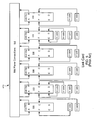
- FIG. 7 illustrates a set 700 of racks 130 of a massively parallel computer system such as the Blue Gene/L computer system that are arranged into a partition in the X dimension.
- Each midplane 132 in each rack 130 is an 8x8x8 torus, where the coordinates of the torus are X, Y, and Z.
- Each rack is arranged in a 8x8x 16 torus since the two midplanes of each rack are arranged in the Z dimension.
- the first rack 710 is rack 0 and has two midplanes R00 712 and R01 714. The remaining racks are similarly numbered R10 through R71.
- the X cables 720 connect the 8 racks in the X dimension and the Y and Z dimensions are wrapped around in a single midplane.
- the X split cables 730 are shown on the right hand side of the drawing but are not used to configure the partition in this example. So the partition shown in Figure 7 is a 128x8x8 torus.
- the X dimension cables 720 can be seen to connect the racks in the order of R0, R1, R3, R5, R7, R6, R4, R2 by following the direction of the X cables into a rack and then leaving the rack to the next rack.
- the coordinates of the nodes in the rack shown in Figure 7 would then be assigned as shown in Table 1.
- Table 1 Rack Node coordinates (X,Y,Z) R0 (0,0,0) - (7,7,16) R1 (8,0,0) - (15,7,16) R2 (56,0,0) - (63,7,16) R3 (16,0,0) (23,7,16) R4 (48,0,0) - (55,7,16) R5 (24,0,0) - (31,7,16) R6 (40,0,0) - (47,7,16) R7 (32,0,0) - (39,7,16)
- Figure 8 illustrates a set of racks 130 of a massively parallel computer system such as the Blue Gene/L computer system similar the set shown in Figure 7 , except now racks R4 810 and R5 812 are configured as a set of back up racks.
- the backup racks 810, 812 are configured to the pass through mode 612 shown in Figure 6 .
- the coordinates of the nodes in the rack shown in Figure 8 would then be assigned as shown in Table 2.
- the backup racks 810, 812 can be configured as a separate partition to be used when the racks are not need as a backup. This can be done using the x split cables 814 shown in Figure 8 .
- the link chips in R4 810 and R5 812 are configured to be in pass through mode as discussed above, in addition these link chips are set in the split cable mode 614 as shown in Figure 6 and discussed above.
- the coordinates of the nodes of racks R4 and R5 would then be assigned as shown in Table 3.
- the backup racks 810, 812 are configured to the normal mode 610 shown in Figure 6 .
- the coordinates of the nodes in the rack shown in Figure 8 are then assigned temporary coordinates that are not in the range of the original coordinates.
- the temporary coordinates allow the data in the original midplane to be copied into the backup midplane.
- An example of the temporary coordinates are shown in Table 4.
- the failed racks R2 and R3 are configured to the pass through mode 610 shown in Figure 6 and the coordinates of the backup racks are then assigned the coordinates that were originally assigned to racks R2 and R3. Therefore, the backup racks now take the place of the original racks R2 and R3 as shown in Table 5.
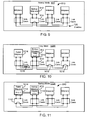
- Figure 9 illustrates a simplified representation of a set of midplanes similar to those shown in Figure 8 .
- Figure 9 illustrates a normal mode of operation 900 for a partition 910 set up for fast backup.
- Four midplanes are shown connected in the X dimension with a single midplane 912 serving as a backup in the manner described above with reference to Figure 8 .
- the backup midplane 912 has its link cards 914 configured in the pass through mode 610 ( Figure 6 ).
- the normal mode of operation 900 is set up by the service node setting up the partition for backup operation by setting the backup rack or racks into the pass through mode as described above.
- Application jobs can then be scheduled on the partition until there is a need for a fast backup of the nodes in a midplane by copying the data in all the nodes to the backup midplane.
- Figure 10 shows a block diagram that represents the partition 1010 of a massively parallel computer system shown in Figure 9 during the copy mode 1000.
- the fast backup mechanism 142 begins a fast backup of all the nodes on the midplane with the copy mode 1000.
- copy mode 1000 the application or job running on the partition is suspended.
- the link card 914 for the backup midplane 912 is placed in the normal mode 610 ( Figure 6 ).
- the link cards 1018 for the other midplanes in the partition can be placed in the pass through mode to simplify the assigning of temporary coordinates.
- the midplane nodes are then assigned temporary coordinates that do not match the values of the midplanes in the original partition so that the nodes in the failed midplane 1012 can be copied into the backup midplane.
- the nodes in the failed midplane 1012 are then instructed to copy their contents to the respective nodes in the backup midplane using the temporary coordinates as shown by the data arrow 1014.
- the nodes copy the entire contents of their memory to the corresponding node in the backup midplane in the manner known in the prior art.
- the copy can be accomplished by software running from the SRAM that receives the destination node from the fast backup mechanism.
- the node then sends the data over the torus network.
- the network hardware (390 Figure 3 ) on each node receives data over the network and passes the data to the next node if the data is intended for a distant node.
- the data has a hop count that indicates how many positions in the torus to move. The hop count is decremented by each node and the last node accepts the data. After all the data in the nodes is copied, the partition can then be placed into the backup mode as shown in Figure 11 .
- Figure 11 shows a block diagram that represents the portion of a massively parallel computer system shown in Figure 10 during the backup mode 1100.
- the partition is placed into the backup mode as shown in Figure 11 by configuring the link cards 1112 of the failed midplane 1114 to the pass through mode 610 ( Figure 6 ). Further, the coordinates 1116 of the failed midplane 1114 are copied to the coordinates 1010 of the backup midplane 912. The job that was suspended on the partition 910 can now be resumed and continue processing without reloading or restarting the job.
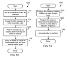
- Figure 12 shows a method 1200 for fast backup copying of nodes in a parallel computer system by the fast backup mechanism 142.
- the method operates to fast backup an original job operating on an original midplane to a backup midplane.
- setup a midplane or rack as a backup step 1210).
- suspend all traffic between all nodes executing a job step 1220.
- perform a fast backup by copying data from nodes in an original midplane to corresponding nodes in a backup midplane step 1230.
- notify all the nodes in the partition executing the job that they can resume the suspended job and start network traffic again (step 1240).
- Figure 13 shows a method 1210 for setting up one or more midplanes as a backup and represents one possible implementation for step 1210 in Figure 12 .
- Figure 14 shows a method 1230 as one possible implementation for step 1230 in Figure 12 .
- Method 1230 illustrates performing a fast backup of compute nodes by copying all the node data in a parallel computer system from an original or failed midplane or rack of nodes to a backup midplane or rack of nodes. The method would be executed by the fast backup mechanism 142 on the service node 140. First, terminate any jobs running on the backup midplane if there are any (step 1410). Next, program the link chips on the backup midplane to the normal mode to accept data (step 1420). Then assign temporary coordinates to the nodes in the backup midplane (step 1430).
- step 1440 notify all the nodes in the original or failed midplane to send all data on the node to the corresponding node in the backup midplane (step 1440).
- step 1450 program the link chips in the original midplane to the pass through mode (step 1450).
- step 1460 switch the coordinates in the backup midplane to match the coordinates of the original midplane to configure the backup midplane to take the place of the original midplane (step 1460), and the method is then done.
- embodiments provide a method and apparatus for fast backup of a set of nodes in a computer system such as a massively parallel super computer system.
- Embodiments herein can significantly decrease the amount of down time for increased efficiency of the computer system.
Landscapes
- Engineering & Computer Science (AREA)
- Theoretical Computer Science (AREA)
- Quality & Reliability (AREA)
- Physics & Mathematics (AREA)
- General Engineering & Computer Science (AREA)
- General Physics & Mathematics (AREA)
- Hardware Redundancy (AREA)
- Multi Processors (AREA)
Claims (12)
- Parallelcomputersystem, das Folgendes umfasst:eine Vielzahl von Mittelplatten, wobei jede Mittelplatte eine Vielzahl von miteinander verbundenen Rechenknoten mit Knotendaten und eine Vielzahl von Verbindungs-Chips umfasst, welche die Vielzahl von Mittelplatten mit einer Gruppe von Kabeln verbinden, die wiederum die Vielzahl von Mittelplatten miteinander verbinden;einen Schnellsicherungsmechanismus in einem Dienstknoten des Computersystems, der eine Mittelplatte als eine Sicherungsmittelplatte einrichtet, indem die Vielzahl von Verbindungs-Chips auf der Sicherungsmittelplatte in eine Durchgangsbetriebsart gesetzt werden, die Daten, welche von einem ersten Verbindungs-Chips auf der Sicherungsmittelplatte kommen, an einen zweiten Verbindungs-Chip auf einer benachbarten Mittelplatte weiterleitet; undwobei der Schnellsicherungsmechanismus alle Knoten auf einer ursprünglichen Mittelplatte anweist, alle ihre Daten in entsprechende Knoten auf der Sicherungsmittelplatte zu kopieren, wobei vorübergehende Koordinaten für die entsprechenden Knoten auf der Sicherungsmittelplatte verwendet werden.
- Parallelcomputersystem nach Anspruch 1, wobei der Schnellsicherungsmechanismus Knotenkoordinaten auf der Sicherungsmittelplatte auf eine Gruppe von Koordinaten setzt, die der ursprünglichen Mittelplatte entsprechen, und die Vielzahl von Verbindungs-Chips auf der ursprünglichen Mittelplatte in die Durchgangsbetriebsart setzt.
- Parallelcomputersystem nach Anspruch 1, wobei die Rechenknoten auf der Mittelplatte mit einem Torusnetzwerk miteinander verbunden sind, um jeden Knoten mit seinen sechs am nächsten gelegenen Nachbarn zu verbinden.
- Parallelcomputersystem nach Anspruch 3, das des Weiteren Kabel umfasst, um die Mittelplatten mit ihren sechs am nächsten gelegenen Nachbarn zu verbinden.
- Parallelcomputersystem nach Anspruch 1, das des Weiteren Kopiercode im statischen Direktzugriffspeicher (SRAM) umfasst, um alle Daten in den Rechenknoten der ursprünglichen Mittelplatte in die entsprechenden Knoten auf der Sicherungsmittelplatte zu kopieren.
- Verfahren für die schnelle Sicherung von Computerknoten in einem Parallelcomputersystem, wobei das Verfahren die folgenden Schritte umfasst:Einrichten einer aus einer Vielzahl von Mittelplatten, wobei jede Mittelplatte eine Vielzahl von miteinander verbundenen Rechenknoten mit Knotendaten und eine Vielzahl von Verbindungs-Chips umfasst, welche die Vielzahl von Mittelplatten mit einer Gruppe von Kabeln verbinden, die wiederum die Vielzahl von Mittelplatten miteinander verbinden;Einrichten einer Mittelplatte als eine Sicherungsmittelplatte und Setzen der Vielzahl von Verbindungs-Chips auf der Sicherungsmittelplatte in eine Durchgangsbetriebsart, die Daten, welche von einem ersten Verbindungs-Chip auf der Sicherungsmittelplatte kommen, an einen zweiten Verbindungs-Chip auf einer benachbarten Mittelplatte weiterleitet; undAnweisen aller Knoten auf einer ursprünglichen Mittelplatte, alle ihre Daten in entsprechende Knoten auf der Sicherungsmittelplatte zu kopieren, wobei vorübergehende Koordinaten für die entsprechenden Knoten auf der Sicherungsmittelplatte verwendet werden.
- Verfahren nach Anspruch 6, wobei der Schritt des Einrichtens einer aus einer Vielzahl von Mittelplatten als eine Sicherungsmittelplatte weiter die folgenden Schritte umfasst:Programmieren einer Vielzahl von Verbindungs-Chips auf der Sicherungsmittelplatte für die Durchgangsbetriebsart;Programmieren von Verbindungs-Chips auf einer Vielzahl von verbleibenden Mittelplatten als eine Partition, um Knotendaten an benachbarte Mittelplatten weiterzuleiten; undEinplanen eines Auftrags, der auf der Partition ausgeführt werden soll.
- Verfahren nach Anspruch 6, wobei der Schritt des Anweisens weiter die folgenden Schritte umfasst:Programmieren der Vielzahl von Verbindungs-Chips auf der Sicherungsmittelplatte für die Normalbetriebsart, um Daten anzunehmen;Zuweisen vorübergehender Koordinaten zu den Knoten auf der Sicherungsmittelplatte; undBenachrichtigen aller Knoten auf der ursprünglichen Mittelplatte, alle Daten in dem Knoten an den entsprechenden Knoten auf der Sicherungsmittelplatte zu senden.
- Verfahren nach Anspruch 8, das des Weiteren die folgenden Schritte umfasst: Programmieren der Verbindungs-Chips auf der ursprünglichen Mittelplatte für die Durchgangsbetriebsart; und Wechseln der Koordinaten auf der Sicherungsmittelplatte, sodass sie mit den Koordinaten der ursprünglichen Mittelplatte übereinstimmen, um die Sicherungsmittelplatte so zu konfigurieren, dass sie an die Stelle der ursprünglichen Mittelplatte tritt.
- Verfahren nach Anspruch 8, das ferner den folgenden Schritt umfasst:Beenden aller etwaig vorhandenen Aufträge, die auf der Sicherungsmittelplatte ausgeführt werden.
- Verfahren nach Anspruch 8, wobei der Schritt des Kopierens von Daten von der ursprünglichen Mittelplatte auf die Sicherungsmittelplatte mit Kopiercode erfolgt, der sich im SRAM der Rechenknoten befindet.
- Computerprogrammprodukt, das in den internen Speicher eines digitalen Computers geladen werden kann, welches Softwarecodeteile umfasst, um bei Ausführung des Produkts auf einem Computer die Erfindung gemäß den Ansprüchen 6 bis 11 auszuführen.
Applications Claiming Priority (2)
| Application Number | Priority Date | Filing Date | Title |
|---|---|---|---|
| US11/608,891 US7512836B2 (en) | 2006-12-11 | 2006-12-11 | Fast backup of compute nodes in failing midplane by copying to nodes in backup midplane via link chips operating in pass through and normal modes in massively parallel computing system |
| PCT/EP2007/063022 WO2008071555A1 (en) | 2006-12-11 | 2007-11-29 | Fast backup of compute nodes in a massively parallel computer system |
Publications (3)
| Publication Number | Publication Date |
|---|---|
| EP2118749A1 EP2118749A1 (de) | 2009-11-18 |
| EP2118749B1 true EP2118749B1 (de) | 2010-07-07 |
| EP2118749B9 EP2118749B9 (de) | 2010-11-03 |
Family
ID=39030857
Family Applications (1)
| Application Number | Title | Priority Date | Filing Date |
|---|---|---|---|
| EP07847538A Not-in-force EP2118749B9 (de) | 2006-12-11 | 2007-11-29 | Schnelles backup von datenverarbeitungsknoten in einem massiv parallelen computersystem |
Country Status (6)
| Country | Link |
|---|---|
| US (1) | US7512836B2 (de) |
| EP (1) | EP2118749B9 (de) |
| KR (1) | KR101039185B1 (de) |
| AT (1) | ATE473482T1 (de) |
| DE (1) | DE602007007672D1 (de) |
| WO (1) | WO2008071555A1 (de) |
Families Citing this family (6)
| Publication number | Priority date | Publication date | Assignee | Title |
|---|---|---|---|---|
| US20080288630A1 (en) * | 2007-05-18 | 2008-11-20 | Motorola, Inc. | Device management |
| US7783813B2 (en) * | 2007-06-14 | 2010-08-24 | International Business Machines Corporation | Multi-node configuration of processor cards connected via processor fabrics |
| US20100017655A1 (en) * | 2008-07-16 | 2010-01-21 | International Business Machines Corporation | Error Recovery During Execution Of An Application On A Parallel Computer |
| JP4789021B2 (ja) * | 2009-02-06 | 2011-10-05 | 日本電気株式会社 | データ処理装置及びデータ処理方法 |
| US8140889B2 (en) * | 2010-08-23 | 2012-03-20 | International Business Machines Corporation | Dynamically reassigning a connected node to a block of compute nodes for re-launching a failed job |
| JP5994601B2 (ja) * | 2012-11-27 | 2016-09-21 | 富士通株式会社 | 並列計算機、並列計算機の制御プログラム及び並列計算機の制御方法 |
Family Cites Families (7)
| Publication number | Priority date | Publication date | Assignee | Title |
|---|---|---|---|---|
| DE3215177A1 (de) * | 1982-04-23 | 1983-10-27 | Hartmann & Braun Ag, 6000 Frankfurt | Ueberwachungssystem fuer eine oder mehrere, gleichartig aufgebaute prozessstationen |
| US5533198A (en) * | 1992-11-30 | 1996-07-02 | Cray Research, Inc. | Direction order priority routing of packets between nodes in a networked system |
| JP3980488B2 (ja) * | 2001-02-24 | 2007-09-26 | インターナショナル・ビジネス・マシーンズ・コーポレーション | 超並列コンピュータ・システム |
| CN1319237C (zh) * | 2001-02-24 | 2007-05-30 | 国际商业机器公司 | 超级计算机中通过动态重新划分的容错 |
| US6832270B2 (en) * | 2002-03-08 | 2004-12-14 | Hewlett-Packard Development Company, L.P. | Virtualization of computer system interconnects |
| JP2004079573A (ja) * | 2002-08-09 | 2004-03-11 | Murata Mfg Co Ltd | コイル部品 |
| US7711977B2 (en) | 2004-04-15 | 2010-05-04 | Raytheon Company | System and method for detecting and managing HPC node failure |
-
2006
- 2006-12-11 US US11/608,891 patent/US7512836B2/en not_active Expired - Fee Related
-
2007
- 2007-11-29 KR KR1020097010650A patent/KR101039185B1/ko not_active Expired - Fee Related
- 2007-11-29 EP EP07847538A patent/EP2118749B9/de not_active Not-in-force
- 2007-11-29 AT AT07847538T patent/ATE473482T1/de not_active IP Right Cessation
- 2007-11-29 WO PCT/EP2007/063022 patent/WO2008071555A1/en not_active Ceased
- 2007-11-29 DE DE602007007672T patent/DE602007007672D1/de active Active
Also Published As
| Publication number | Publication date |
|---|---|
| US7512836B2 (en) | 2009-03-31 |
| WO2008071555A1 (en) | 2008-06-19 |
| US20080140735A1 (en) | 2008-06-12 |
| EP2118749A1 (de) | 2009-11-18 |
| ATE473482T1 (de) | 2010-07-15 |
| KR101039185B1 (ko) | 2011-06-03 |
| EP2118749B9 (de) | 2010-11-03 |
| DE602007007672D1 (de) | 2010-08-19 |
| KR20090084888A (ko) | 2009-08-05 |
Similar Documents
| Publication | Publication Date | Title |
|---|---|---|
| EP2147375B1 (de) | Fehlerbehebung in einem parallelen computersystem mit einem torus-netzwerk | |
| JP3794151B2 (ja) | クロスバースイッチを有する情報処理装置およびクロスバースイッチ制御方法 | |
| JP3459056B2 (ja) | データ転送システム | |
| EP0848327B1 (de) | Multiprozessorrechner mit konfigurierbaren Harwaresystembereichen | |
| US7334070B2 (en) | Multi-channel memory architecture for daisy chained arrangements of nodes with bridging between memory channels | |
| CN101663649B (zh) | 动态地重新路由并行计算机系统上的节点业务 | |
| EP2118749B1 (de) | Schnelles backup von datenverarbeitungsknoten in einem massiv parallelen computersystem | |
| JPH08241218A (ja) | コンピュータシステムおよび並列コンピュータシステムにおいて実行される複数のスレッド間を通信する方法 | |
| EP1573978B1 (de) | System und verfahren zur programmierung der hyperdatentransportleitweglenkungstabelle in multiprozessorsystemen | |
| JPH11143729A (ja) | フォールトトレラントコンピュータ | |
| US7620841B2 (en) | Re-utilizing partially failed resources as network resources | |
| CN120448141A (zh) | 共享内存资源池的系统、服务器、方法、介质及程序产品 | |
| WO2008019955A1 (en) | Apparatus, system, and method for integrating multiple raid storage instances within a blade centre | |
| US7103639B2 (en) | Method and apparatus for processing unit synchronization for scalable parallel processing | |
| US7353418B2 (en) | Method and apparatus for updating serial devices | |
| RU2810634C2 (ru) | Способ повышения надежности систем хранения данных и соответствующее устройство | |
| JPH0462641A (ja) | マルチプロセッサシステム | |
| Sadawarti et al. | Fault-tolerant routing in unique-path multistage interconnection networks | |
| Shimizu et al. | Fujitsu PRIMEQUEST: 32-way SMP Open Servers with Powerful Reliability |
Legal Events
| Date | Code | Title | Description |
|---|---|---|---|
| PUAI | Public reference made under article 153(3) epc to a published international application that has entered the european phase |
Free format text: ORIGINAL CODE: 0009012 |
|
| 17P | Request for examination filed |
Effective date: 20090630 |
|
| AK | Designated contracting states |
Kind code of ref document: A1 Designated state(s): AT BE BG CH CY CZ DE DK EE ES FI FR GB GR HU IE IS IT LI LT LU LV MC MT NL PL PT RO SE SI SK TR |
|
| 17Q | First examination report despatched |
Effective date: 20091106 |
|
| DAX | Request for extension of the european patent (deleted) | ||
| GRAP | Despatch of communication of intention to grant a patent |
Free format text: ORIGINAL CODE: EPIDOSNIGR1 |
|
| GRAS | Grant fee paid |
Free format text: ORIGINAL CODE: EPIDOSNIGR3 |
|
| GRAA | (expected) grant |
Free format text: ORIGINAL CODE: 0009210 |
|
| AK | Designated contracting states |
Kind code of ref document: B1 Designated state(s): AT BE BG CH CY CZ DE DK EE ES FI FR GB GR HU IE IS IT LI LT LU LV MC MT NL PL PT RO SE SI SK TR |
|
| REG | Reference to a national code |
Ref country code: GB Ref legal event code: FG4D |
|
| REG | Reference to a national code |
Ref country code: CH Ref legal event code: NV Representative=s name: IBM RESEARCH GMBH ZURICH RESEARCH LABORATORY INTEL Ref country code: CH Ref legal event code: EP |
|
| REG | Reference to a national code |
Ref country code: IE Ref legal event code: FG4D |
|
| REF | Corresponds to: |
Ref document number: 602007007672 Country of ref document: DE Date of ref document: 20100819 Kind code of ref document: P |
|
| REG | Reference to a national code |
Ref country code: GB Ref legal event code: 746 Effective date: 20100716 |
|
| REG | Reference to a national code |
Ref country code: NL Ref legal event code: VDEP Effective date: 20100707 |
|
| PG25 | Lapsed in a contracting state [announced via postgrant information from national office to epo] |
Ref country code: SI Free format text: LAPSE BECAUSE OF FAILURE TO SUBMIT A TRANSLATION OF THE DESCRIPTION OR TO PAY THE FEE WITHIN THE PRESCRIBED TIME-LIMIT Effective date: 20100707 |
|
| LTIE | Lt: invalidation of european patent or patent extension |
Effective date: 20100707 |
|
| PG25 | Lapsed in a contracting state [announced via postgrant information from national office to epo] |
Ref country code: NL Free format text: LAPSE BECAUSE OF FAILURE TO SUBMIT A TRANSLATION OF THE DESCRIPTION OR TO PAY THE FEE WITHIN THE PRESCRIBED TIME-LIMIT Effective date: 20100707 Ref country code: LT Free format text: LAPSE BECAUSE OF FAILURE TO SUBMIT A TRANSLATION OF THE DESCRIPTION OR TO PAY THE FEE WITHIN THE PRESCRIBED TIME-LIMIT Effective date: 20100707 Ref country code: FI Free format text: LAPSE BECAUSE OF FAILURE TO SUBMIT A TRANSLATION OF THE DESCRIPTION OR TO PAY THE FEE WITHIN THE PRESCRIBED TIME-LIMIT Effective date: 20100707 Ref country code: AT Free format text: LAPSE BECAUSE OF FAILURE TO SUBMIT A TRANSLATION OF THE DESCRIPTION OR TO PAY THE FEE WITHIN THE PRESCRIBED TIME-LIMIT Effective date: 20100707 |
|
| PG25 | Lapsed in a contracting state [announced via postgrant information from national office to epo] |
Ref country code: BG Free format text: LAPSE BECAUSE OF FAILURE TO SUBMIT A TRANSLATION OF THE DESCRIPTION OR TO PAY THE FEE WITHIN THE PRESCRIBED TIME-LIMIT Effective date: 20101007 Ref country code: CY Free format text: LAPSE BECAUSE OF FAILURE TO SUBMIT A TRANSLATION OF THE DESCRIPTION OR TO PAY THE FEE WITHIN THE PRESCRIBED TIME-LIMIT Effective date: 20100707 Ref country code: PT Free format text: LAPSE BECAUSE OF FAILURE TO SUBMIT A TRANSLATION OF THE DESCRIPTION OR TO PAY THE FEE WITHIN THE PRESCRIBED TIME-LIMIT Effective date: 20101108 Ref country code: PL Free format text: LAPSE BECAUSE OF FAILURE TO SUBMIT A TRANSLATION OF THE DESCRIPTION OR TO PAY THE FEE WITHIN THE PRESCRIBED TIME-LIMIT Effective date: 20100707 Ref country code: IS Free format text: LAPSE BECAUSE OF FAILURE TO SUBMIT A TRANSLATION OF THE DESCRIPTION OR TO PAY THE FEE WITHIN THE PRESCRIBED TIME-LIMIT Effective date: 20101107 |
|
| PG25 | Lapsed in a contracting state [announced via postgrant information from national office to epo] |
Ref country code: LV Free format text: LAPSE BECAUSE OF FAILURE TO SUBMIT A TRANSLATION OF THE DESCRIPTION OR TO PAY THE FEE WITHIN THE PRESCRIBED TIME-LIMIT Effective date: 20100707 Ref country code: GR Free format text: LAPSE BECAUSE OF FAILURE TO SUBMIT A TRANSLATION OF THE DESCRIPTION OR TO PAY THE FEE WITHIN THE PRESCRIBED TIME-LIMIT Effective date: 20101008 Ref country code: SE Free format text: LAPSE BECAUSE OF FAILURE TO SUBMIT A TRANSLATION OF THE DESCRIPTION OR TO PAY THE FEE WITHIN THE PRESCRIBED TIME-LIMIT Effective date: 20100707 Ref country code: BE Free format text: LAPSE BECAUSE OF FAILURE TO SUBMIT A TRANSLATION OF THE DESCRIPTION OR TO PAY THE FEE WITHIN THE PRESCRIBED TIME-LIMIT Effective date: 20100707 |
|
| PG25 | Lapsed in a contracting state [announced via postgrant information from national office to epo] |
Ref country code: DK Free format text: LAPSE BECAUSE OF FAILURE TO SUBMIT A TRANSLATION OF THE DESCRIPTION OR TO PAY THE FEE WITHIN THE PRESCRIBED TIME-LIMIT Effective date: 20100707 |
|
| PLBE | No opposition filed within time limit |
Free format text: ORIGINAL CODE: 0009261 |
|
| STAA | Information on the status of an ep patent application or granted ep patent |
Free format text: STATUS: NO OPPOSITION FILED WITHIN TIME LIMIT |
|
| PG25 | Lapsed in a contracting state [announced via postgrant information from national office to epo] |
Ref country code: SK Free format text: LAPSE BECAUSE OF FAILURE TO SUBMIT A TRANSLATION OF THE DESCRIPTION OR TO PAY THE FEE WITHIN THE PRESCRIBED TIME-LIMIT Effective date: 20100707 Ref country code: CZ Free format text: LAPSE BECAUSE OF FAILURE TO SUBMIT A TRANSLATION OF THE DESCRIPTION OR TO PAY THE FEE WITHIN THE PRESCRIBED TIME-LIMIT Effective date: 20100707 Ref country code: IT Free format text: LAPSE BECAUSE OF FAILURE TO SUBMIT A TRANSLATION OF THE DESCRIPTION OR TO PAY THE FEE WITHIN THE PRESCRIBED TIME-LIMIT Effective date: 20100707 Ref country code: EE Free format text: LAPSE BECAUSE OF FAILURE TO SUBMIT A TRANSLATION OF THE DESCRIPTION OR TO PAY THE FEE WITHIN THE PRESCRIBED TIME-LIMIT Effective date: 20100707 Ref country code: RO Free format text: LAPSE BECAUSE OF FAILURE TO SUBMIT A TRANSLATION OF THE DESCRIPTION OR TO PAY THE FEE WITHIN THE PRESCRIBED TIME-LIMIT Effective date: 20100707 |
|
| 26N | No opposition filed |
Effective date: 20110408 |
|
| PG25 | Lapsed in a contracting state [announced via postgrant information from national office to epo] |
Ref country code: MC Free format text: LAPSE BECAUSE OF NON-PAYMENT OF DUE FEES Effective date: 20101130 Ref country code: ES Free format text: LAPSE BECAUSE OF FAILURE TO SUBMIT A TRANSLATION OF THE DESCRIPTION OR TO PAY THE FEE WITHIN THE PRESCRIBED TIME-LIMIT Effective date: 20101018 |
|
| REG | Reference to a national code |
Ref country code: DE Ref legal event code: R097 Ref document number: 602007007672 Country of ref document: DE Effective date: 20110408 |
|
| PG25 | Lapsed in a contracting state [announced via postgrant information from national office to epo] |
Ref country code: IE Free format text: LAPSE BECAUSE OF NON-PAYMENT OF DUE FEES Effective date: 20101129 |
|
| PG25 | Lapsed in a contracting state [announced via postgrant information from national office to epo] |
Ref country code: MT Free format text: LAPSE BECAUSE OF FAILURE TO SUBMIT A TRANSLATION OF THE DESCRIPTION OR TO PAY THE FEE WITHIN THE PRESCRIBED TIME-LIMIT Effective date: 20100707 |
|
| REG | Reference to a national code |
Ref country code: CH Ref legal event code: PL |
|
| PG25 | Lapsed in a contracting state [announced via postgrant information from national office to epo] |
Ref country code: CH Free format text: LAPSE BECAUSE OF NON-PAYMENT OF DUE FEES Effective date: 20111130 Ref country code: LI Free format text: LAPSE BECAUSE OF NON-PAYMENT OF DUE FEES Effective date: 20111130 |
|
| PG25 | Lapsed in a contracting state [announced via postgrant information from national office to epo] |
Ref country code: HU Free format text: LAPSE BECAUSE OF FAILURE TO SUBMIT A TRANSLATION OF THE DESCRIPTION OR TO PAY THE FEE WITHIN THE PRESCRIBED TIME-LIMIT Effective date: 20110108 Ref country code: LU Free format text: LAPSE BECAUSE OF NON-PAYMENT OF DUE FEES Effective date: 20101129 |
|
| PG25 | Lapsed in a contracting state [announced via postgrant information from national office to epo] |
Ref country code: TR Free format text: LAPSE BECAUSE OF FAILURE TO SUBMIT A TRANSLATION OF THE DESCRIPTION OR TO PAY THE FEE WITHIN THE PRESCRIBED TIME-LIMIT Effective date: 20100707 |
|
| PGFP | Annual fee paid to national office [announced via postgrant information from national office to epo] |
Ref country code: FR Payment date: 20121206 Year of fee payment: 6 |
|
| REG | Reference to a national code |
Ref country code: FR Ref legal event code: ST Effective date: 20140731 |
|
| PG25 | Lapsed in a contracting state [announced via postgrant information from national office to epo] |
Ref country code: FR Free format text: LAPSE BECAUSE OF NON-PAYMENT OF DUE FEES Effective date: 20131202 |
|
| PGFP | Annual fee paid to national office [announced via postgrant information from national office to epo] |
Ref country code: DE Payment date: 20171207 Year of fee payment: 11 |
|
| PGFP | Annual fee paid to national office [announced via postgrant information from national office to epo] |
Ref country code: GB Payment date: 20171127 Year of fee payment: 11 |
|
| REG | Reference to a national code |
Ref country code: DE Ref legal event code: R119 Ref document number: 602007007672 Country of ref document: DE |
|
| GBPC | Gb: european patent ceased through non-payment of renewal fee |
Effective date: 20181129 |
|
| PG25 | Lapsed in a contracting state [announced via postgrant information from national office to epo] |
Ref country code: DE Free format text: LAPSE BECAUSE OF NON-PAYMENT OF DUE FEES Effective date: 20190601 |
|
| PG25 | Lapsed in a contracting state [announced via postgrant information from national office to epo] |
Ref country code: GB Free format text: LAPSE BECAUSE OF NON-PAYMENT OF DUE FEES Effective date: 20181129 |