EP2118475B1 - Systems and methods for reducing noise from jet engine exhaust - Google Patents
Systems and methods for reducing noise from jet engine exhaust Download PDFInfo
- Publication number
- EP2118475B1 EP2118475B1 EP08728611.8A EP08728611A EP2118475B1 EP 2118475 B1 EP2118475 B1 EP 2118475B1 EP 08728611 A EP08728611 A EP 08728611A EP 2118475 B1 EP2118475 B1 EP 2118475B1
- Authority
- EP
- European Patent Office
- Prior art keywords
- flow
- projections
- nozzle
- engine
- injecting
- Prior art date
- Legal status (The legal status is an assumption and is not a legal conclusion. Google has not performed a legal analysis and makes no representation as to the accuracy of the status listed.)
- Active
Links
Images


Classifications
-
- F—MECHANICAL ENGINEERING; LIGHTING; HEATING; WEAPONS; BLASTING
- F02—COMBUSTION ENGINES; HOT-GAS OR COMBUSTION-PRODUCT ENGINE PLANTS
- F02K—JET-PROPULSION PLANTS
- F02K1/00—Plants characterised by the form or arrangement of the jet pipe or nozzle; Jet pipes or nozzles peculiar thereto
- F02K1/46—Nozzles having means for adding air to the jet or for augmenting the mixing region between the jet and the ambient air, e.g. for silencing
-
- B—PERFORMING OPERATIONS; TRANSPORTING
- B64—AIRCRAFT; AVIATION; COSMONAUTICS
- B64D—EQUIPMENT FOR FITTING IN OR TO AIRCRAFT; FLIGHT SUITS; PARACHUTES; ARRANGEMENTS OR MOUNTING OF POWER PLANTS OR PROPULSION TRANSMISSIONS IN AIRCRAFT
- B64D29/00—Power-plant nacelles, fairings, or cowlings
- B64D29/02—Power-plant nacelles, fairings, or cowlings associated with wings
-
- B—PERFORMING OPERATIONS; TRANSPORTING
- B64—AIRCRAFT; AVIATION; COSMONAUTICS
- B64D—EQUIPMENT FOR FITTING IN OR TO AIRCRAFT; FLIGHT SUITS; PARACHUTES; ARRANGEMENTS OR MOUNTING OF POWER PLANTS OR PROPULSION TRANSMISSIONS IN AIRCRAFT
- B64D33/00—Arrangements in aircraft of power plant parts or auxiliaries not otherwise provided for
- B64D33/04—Arrangements in aircraft of power plant parts or auxiliaries not otherwise provided for of exhaust outlets or jet pipes
-
- F—MECHANICAL ENGINEERING; LIGHTING; HEATING; WEAPONS; BLASTING
- F02—COMBUSTION ENGINES; HOT-GAS OR COMBUSTION-PRODUCT ENGINE PLANTS
- F02K—JET-PROPULSION PLANTS
- F02K1/00—Plants characterised by the form or arrangement of the jet pipe or nozzle; Jet pipes or nozzles peculiar thereto
- F02K1/28—Plants characterised by the form or arrangement of the jet pipe or nozzle; Jet pipes or nozzles peculiar thereto using fluid jets to influence the jet flow
- F02K1/34—Plants characterised by the form or arrangement of the jet pipe or nozzle; Jet pipes or nozzles peculiar thereto using fluid jets to influence the jet flow for attenuating noise
-
- F—MECHANICAL ENGINEERING; LIGHTING; HEATING; WEAPONS; BLASTING
- F02—COMBUSTION ENGINES; HOT-GAS OR COMBUSTION-PRODUCT ENGINE PLANTS
- F02K—JET-PROPULSION PLANTS
- F02K1/00—Plants characterised by the form or arrangement of the jet pipe or nozzle; Jet pipes or nozzles peculiar thereto
- F02K1/38—Introducing air inside the jet
- F02K1/386—Introducing air inside the jet mixing devices in the jet pipe, e.g. for mixing primary and secondary flow
-
- F—MECHANICAL ENGINEERING; LIGHTING; HEATING; WEAPONS; BLASTING
- F02—COMBUSTION ENGINES; HOT-GAS OR COMBUSTION-PRODUCT ENGINE PLANTS
- F02K—JET-PROPULSION PLANTS
- F02K1/00—Plants characterised by the form or arrangement of the jet pipe or nozzle; Jet pipes or nozzles peculiar thereto
- F02K1/46—Nozzles having means for adding air to the jet or for augmenting the mixing region between the jet and the ambient air, e.g. for silencing
- F02K1/48—Corrugated nozzles
-
- F—MECHANICAL ENGINEERING; LIGHTING; HEATING; WEAPONS; BLASTING
- F05—INDEXING SCHEMES RELATING TO ENGINES OR PUMPS IN VARIOUS SUBCLASSES OF CLASSES F01-F04
- F05D—INDEXING SCHEME FOR ASPECTS RELATING TO NON-POSITIVE-DISPLACEMENT MACHINES OR ENGINES, GAS-TURBINES OR JET-PROPULSION PLANTS
- F05D2250/00—Geometry
- F05D2250/10—Two-dimensional
- F05D2250/11—Two-dimensional triangular
-
- F—MECHANICAL ENGINEERING; LIGHTING; HEATING; WEAPONS; BLASTING
- F05—INDEXING SCHEMES RELATING TO ENGINES OR PUMPS IN VARIOUS SUBCLASSES OF CLASSES F01-F04
- F05D—INDEXING SCHEME FOR ASPECTS RELATING TO NON-POSITIVE-DISPLACEMENT MACHINES OR ENGINES, GAS-TURBINES OR JET-PROPULSION PLANTS
- F05D2260/00—Function
- F05D2260/96—Preventing, counteracting or reducing vibration or noise
-
- Y—GENERAL TAGGING OF NEW TECHNOLOGICAL DEVELOPMENTS; GENERAL TAGGING OF CROSS-SECTIONAL TECHNOLOGIES SPANNING OVER SEVERAL SECTIONS OF THE IPC; TECHNICAL SUBJECTS COVERED BY FORMER USPC CROSS-REFERENCE ART COLLECTIONS [XRACs] AND DIGESTS
- Y02—TECHNOLOGIES OR APPLICATIONS FOR MITIGATION OR ADAPTATION AGAINST CLIMATE CHANGE
- Y02T—CLIMATE CHANGE MITIGATION TECHNOLOGIES RELATED TO TRANSPORTATION
- Y02T50/00—Aeronautics or air transport
- Y02T50/60—Efficient propulsion technologies, e.g. for aircraft
Definitions
- the present disclosure is directed generally toward systems and methods for reducing noise (e.g., broadband noise) from jet engines, including via nozzles having chevrons or other projections augmented with proximate injected flows, and/or other mixing enhancement arrangements.
- noise e.g., broadband noise
- Aircraft manufacturers are under continual pressure to reduce the noise produced by aircraft in order to satisfy increasingly stringent noise certification rules.
- Aircraft engines are a major contributor to overall aircraft noise. Accordingly, aircraft engines in particular have been the target of manufacturers' noise reduction efforts.
- Aircraft engines have been made significantly quieter as a result of advanced high bypass ratio engines. These engines derive a significant fraction of their total thrust not directly from jet exhaust, but from bypass air which is propelled around the core of the engine by an engine-driven forwardly mounted fan. While this approach has significantly reduced aircraft noise when compared with pure turbojet engines and low bypass ratio engines, engine and aircraft federal regulations nevertheless continue to require further engine noise reductions.
- Chevrons generally include serrations at the nozzle lip, typically triangular in shape and having some curvature in the lengthwise direction, which slightly immerses them in the adjacent flow.
- the chevrons can project either inwardly or outwardly, by an amount that is on the order of the upstream boundary layer thickness on the inner or outer surface, respectively.
- the chevrons can be located at the trailing edge of the nozzle core flow duct (through which the engine core flow is directed), and/or the trailing edge of the fan flow duct, which is arranged annularly around the core flow duct, and through which the fan bypass air passes.
- the chevrons typically reduce the low-frequency noise by tailoring the rate at which the nozzle flow streams mix with the surrounding freestream air at the length scale of the nozzle diameter.
- Another technique, which may produce a similar noise reduction is to apply high pressure fluid jets (e.g., microjets) at or near the nozzle exit. While the foregoing approaches have resulted in appreciable noise reduction compared with nozzles that do not include chevrons or fluid injection, further noise reduction is desired to meet community noise standards, and to reduce cabin noise.
- EP 1580 418 describes a gas turbine engine in which a plurality of tubes extend approximately one quarter of the way across a chevron for discharging air into the core engine.
- One method for controlling aircraft engine nozzle flow includes generating a first flow of gas with a jet engine and delivering the first flow through a nozzle having a trailing edge perimeter that includes multiple projections (e.g., chevrons) extending in an aft direction.
- the method further includes injecting a pressurized second flow of fluid into the first flow at least proximate to the projections.
- the projections have a generally triangular shape with a tip region positioned aft of a base region.
- the second flow is injected at a position axially aligned with and at a position downstream of the tip region in a streamwise direction.
- the second flow can be changed or halted based at least in part on an engine operating parameter, an aircraft flight condition, or both.
- the second flow can be reduced or halted when the aircraft is at a cruise flight condition.
- the second flow can be varied (e.g., pulsed).
- a method for making an aircraft nozzle system is applied to a nozzle having an exit with an exit perimeter shape that varies in a circumferential direction, and includes identifying target locations around the nozzle exit perimeter where turbulent kinetic energy production levels of jet flow at the nozzle exit are expected to be higher than an average of turbulent kinetic energy production levels around the perimeter.
- the method can further include positioning mixing enhancement devices (e.g., vortex generators, elongated extensions, and/or fluid injection apertures) at the target locations.
- the nozzle includes projections at the exit perimeter, the projections having a generally triangular shape with a tip positioned aft of a base.
- Positioning the mixing enhancement devices includes positioning individual flow injection apertures to be axially aligned with corresponding projection tips in a streamwise direction, with the apertures located aft of the corresponding tips.
- the apertures may be angled inwardly at an acute angle relative to the corresponding tips.
- An alternative method includes generating a flow of gas with a jet engine and delivering the flow through a nozzle having a trailing edge perimeter including multiple projections extending in an aft direction.
- the method still further includes increasing flow vorticity, decreasing shear stress, or both adding to vorticity and decreasing shear stress at locations proximate to the projections.
- the flow vorticity is increased and/or the shear stress is decreased at tip regions of the projections via mixing enhancement devices.
- the mixing enhancement devices can include vortex generators, elongated extensions, and/or fluid injection ports.
- Still another aspect is directed to an aircraft system that includes a jet engine exhaust nozzle having an exit aperture with a perimeter that includes multiple projections extending in an aft direction.
- the system further includes multiple flow injection passages having apertures positioned at least proximate to the projections, with the flow injection passages being coupled to a source of pressurized gas.
- the system can also include at least one valve coupled to at least one of the flow injection passages to control flow through the at least one passage.
- the system can further include a controller operatively coupled to the at least one valve, with the controller programmed to receive input corresponding to an engine operating condition, a flight condition, or both.
- the controller is also programmed to direct the valve based at least in part on the input.
- An aircraft system that includes a jet engine nozzle having an exit aperture with a perimeter that includes multiple projections extending in an aft direction.
- the system further includes mixing enhancement devices carried by the projections, with the mixing enhancement devices being positioned to increase vorticity, decrease shear stress, or both increase vorticity and decrease shear stress at locations proximate to the projections.
- the mixing enhancement devices include flow injection passages having apertures positioned at least proximate to the projections and flow injection passages coupled to a source of pressurized gas.
- the projections are generally triangular in shape with a tip positioned aft of a base, and the mixing enhancement devices include elongated extensions extending aft from the tip of the projection.
- the individual apertures are axially aligned with corresponding tip regions in a streamwise direction and the individual apertures are positioned aft of the corresponding tip region.
- aspects of the present disclosure are directed to jet engine nozzles with chevrons or other projections, and mixing enhancement devices, along with associated systems and methods. Specific details of certain embodiments are described below with reference to Figures 1-10B . Several details of structures or processes that are well-known and often associated with such systems and processes are not set forth in the following description for purposes o.f brevity. Moreover, although the following disclosure sets forth several embodiments of different aspects of the invention, several other embodiments of the invention can have different configurations or different components than those described in this section.
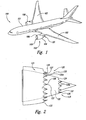
- FIG 1 is an illustration of a commercial jet transport aircraft 100 having wings 102, a fuselage 101, and a propulsion system 103.
- the illustrated propulsion system 103 includes two engines 106 carried by the wings 102.
- Each engine 106 is housed in a nacelle 104, which includes an inlet 105 and a nozzle 120,
- the nozzles 120 include both aft-extending projections and injected flow or other mixing enhancement arrangements, discussed in greater detail below, that reduce the noise generated by the engines 106.
- the noise reduction achieved by these features may be applied to engines carried in the configuration shown in Figure 1 , or, alternatively, may be applied to engines carried in accordance with other configurations, including those discussed later with reference to Figure 6 .
- FIG 2 is an enlarged side elevation view of the nozzle 120 shown in Figure 1 , configured in accordance with an embodiment of the invention.
- the nozzle 120 can include a core flow path 122 that carries engine exhaust products, and a fan flow path 121 disposed annularly around the core flow path 122 for conveying bypass fan flow air.
- the core flow path 122 terminates at a core flow exit 124, and the fan flow path 121 terminates at a fan flow exit 123.
- Either or both of the exits 123, 124 can include projections 125, having a "chevron" shape or another shape that is arranged to enhance mixing between the gas streams merging at the corresponding exit.
- the nozzle 120 is shown with both fan flow projections 125a and core flow projections 125b, but in particular installations, one or the other of these sets of projections 125a, 125b may be eliminated.
- some or all of the projections 125 can include a corresponding mixing enhancement device 150.
- the mixing enhancement device 150 includes a flow injection passage 126 (a portion of which is shown in hidden lines in Figure 2 ) having a passage aperture 127.
- the flow injection passages 126 carry high pressure fluid (e.g., a gas, such as air, or a liquid) and are oriented in a generally aftward direction proximate to the projections 125.
- the combination of the projections 125 and the high pressure flow introduced by the flow injection passages 126 is expected to reduce engine noise by an amount greater than that achievable with either projections or flow injection alone.
- Mixing enhancement devices that include injected flows are described further below with reference to Figures 3-8B , and other mixing enhancement devices are described later with reference to Figures 9A-10B .
- Figure 3 is an enlarged plan view of a portion of the nozzle 120 Illustrating representative projections 125 configured in accordance with an embodiment of the invention.
- the projections 125 have a generally chevron or triangular shape, with a tip region 128 positioned aft of a base region 129.
- the tip region 128 of each projection 125 terminates at an aft-most tip 130.
- the flow injection passages 126 and the associated passage apertures 127 are axially aligned (in a streamwise direction) with the tip region 128. It is believed that this location for the passage apertures 127 will improve the noise reduction capability of the nozzle 120 when compared with other locations for the passage apertures 127.
- the turbulent kinetic energy production of the nozzle flow adjacent to the projections 125 is higher near the tips 130 than near the base regions 129. It is further believed that the turbulent kinetic energy production levels are reduced by the introduction of high pressure, microjet injected flow. Accordingly, the passage aperture 127 can be deliberately positioned at or near the tip 130 to compensate for the expected relatively high turbulent kinetic energy production level at this location. It is further expected that this arrangement will reduce sound levels below the levels achievable with the projections 125 alone.
- individual passage apertures 127 are positioned aft of the corresponding tips 130.
- the passage apertures 127 are located just aft of tips 130.
- each passage aperture 127 can be located downstream of the corresponding tip 130 by a distance of about 20% of the axial length of the projection 125.
- the passage aperture 127 can be located at the tip 130, or just upstream of the tip 130, though it is expected that the downstream location will produce better noise reduction.
- the passage aperture 127 can be positioned downstream of the corresponding tip 130 by a distance of up to about one nozzle diameter (e.g., the diameter of the nozzle 120 at the perimeter location from which the projection 125 extends).
- a single flow injection aperture 127 is shown for an individual projection 125; in other embodiments, individual projections include multiple apertures 127 side-by-side near the tip 130. This arrangement can reduce the size of each aperture 127 and associated flow passage 126, without reducing the injected mass flow.
- the apertures 127 can be oriented to have a zero azimuthal angle Z (as shown in Figure 3 ) or a non-zero azimuthal angle in other embodiments.
- the azimuthal angle Z may be non-zero when the projection 125 includes a single aperture 127, and/or when the projection 125 includes multiple apertures 127. In the latter case, the apertures 127 on a given projection 125 may be directed toward each other or away from each other.
- the projections 125 may, in at least some embodiments, also be movable relative to the rest of the nozzle 120.
- the projections 125 can pivot along a hinge line 131 relative to the rest of the nozzle 120 to alter the degree to which each projection 125 is immersed in (e.g., inclined relative to) the upstream nozzle flow.
- the projections 125 can be formed from a resilient flexible material and, when actuated, form a continuously curved, immersed surface, rather than a surface with a discontinuity at the hinge line 131.
- the noise reduction and overall efficiency of the nozzle 120 can be adjusted by adjusting the flow through the flow injection passages 126, optionally in combination with adjusting the orientation of the projections 125.
- Figure 4 is a partially schematic, side cross-sectional view of a portion of the nozzle 120, one of the projections 125, and the associated flow injection passage 126.
- the flow injection passage 126 is coupled to a source 140 of pressurized gas.
- the source 140 can provide compressed air or another gas (e.g., exhaust gas) to the flow injection passage 126.
- the source 140 can include the engine compressor, which provides compressed air to the flow injection passage 126 via a bleed air port.
- high pressure air can be provided by other sources, e.g., an aircraft auxiliary power unit (APU).
- APU aircraft auxiliary power unit
- the passage aperture 127 is axially aligned in a streamwise direction with the tip 130 of the projection 125.
- the flow axis of the flow injection passage 126 at the passage aperture 127 can be inclined by an angle A relative to the adjacent flow direction of gas passing along an inner surface 132 of the nozzle 120 (indicated by arrow G).
- the inclination angle A can be an acute angle having a selected value of between 0° and ⁇ 90°. In a particular embodiment, the inclination angle A is about 60° relative to the internal gas flow direction G.
- the particular inclination angle A selected for the passage aperture 127 can have other values in other embodiments, and can be selected for a particular installation based on factors that can include the nozzle pressure ratio, particular nozzle geometry features, and the shape of the projection 125, among other factors. For example, when the projection 125 is immersed inwardly (as shown in Figure 4 ), angle A can have a positive value. In a multi-stream installation (e.g., with a bypass flow stream located annularly outwardly from a core flow stream), the projection 125 may be located between the two streams and immersed in an outward direction into the bypass flow stream. In such an instance, angle A may have a negative value.
- the passage aperture 127 is round. In other embodiments, the shape and/or size of the passage aperture 127 can be different, depending, for example, upon the size of the engine and nozzle, and/or installation details.
- aspects of the projections 125 and/or the flow injection passages 126 may be selectively changed and/or otherwise controlled during operation.
- the nozzle 120 can include one or more actuators 134 that are coupled to the projections 125 to rotate them (as indicated by arrow I) in a manner that alters the degree of immersion for each projection 125.
- the projections 125 can be controlled so as to move independently of each other, or all together.
- the flow injection passages 126 can include flexible tubing or other adaptable, conformable and/or resilient structures.
- the flow injection passages 126 may also be coupled to one or more valves 135 to control the flow through each passage 126 and the associated passage aperture 127.
- a controller 136 can be operatively coupled to the valves 135 and the actuator 134 to direct the operation of these components during flight.
- the controller 136 can receive engine inputs 137 (e.g., engine thrust levels), flight condition inputs 138 (e.g., indications of the current and/or upcoming flight condition, such as takeoff, landing, cruise, or others), and/or other inputs 139 (e.g., pilot inputs). Based on the inputs 137-139, the controller 136 can direct the motion of the projections 125 and/or the amount of flow passing through the flow passages 126.
- engine inputs 137 e.g., engine thrust levels
- flight condition inputs 138 e.g., indications of the current and/or upcoming flight condition, such as takeoff, landing, cruise, or others
- other inputs 139 e.g., pilot inputs
- the controller 136 can direct the maximum (or a relatively high) amount of flow through the flow passages 126, and, optionally, can move the projections 125 to the immersion angle expected to reduce noise by the greatest amount.
- a condition may occur during takeoff when the engine is set at or close to its maximum thrust level.
- the need to operate the engine efficiently may outweigh the need to reduce engine noise beyond a threshold level.
- the controller 136 can reduce or halt the flow of pressurized air through the flow passages 126, and can adjust the immersion angle I of the projections 125 to be at or close to zero.
- the controller 136 can include a feedback loop to control exhaust noise.
- the other inputs 139 can include inputs from a microphone, pressure sensor or other sensor that directly or indirectly detects engine exhaust noise levels.
- the controller 136 then adjusts the operating parameters for the projections 125 and/or flow passages 126 to provide the desired (e.g., optimal) level of noise reduction.
- the flow can be varied, e.g., pulsed or otherwise directed in a time-varying manner.
- the foregoing parameters can be adjusted automatically based on the received inputs, and/or can be overridden, adjusted, or otherwise manipulated by the pilot.
- the controller 136 can accordingly include a computer having a processor, memory, input/output capabilities, and a computer-readable medium having computer-executable instructions.
- the function of the computer can be integrated with existing aircraft computers, or the computer can include a standalone unit that communicates with other aircraft systems.
- the amount of injected flow can be less than or equal to 5% of the overall engine mass flow.
- the amount of injected flow can be about 1% or less (e.g., 0.5%) of the overall engine mass flow at takeoff conditions.
- the amount of injected flow can be reduced or eliminated at other engine settings and/or flight conditions.
- One feature of at least some of the foregoing embodiments is that the flow of fluid (e.g., a gas or a liquid) through the flow passages 126 can be adjusted in a manner that depends upon the relative need for noise reduction and the relative need for efficient engine operation. While this arrangement can be supplemented by movable projections 125, it may also be easier to implement than movable projections, and can accordingly be used in lieu of movable projections 125. An advantage of this arrangement is that it can allow the operator to control engine noise reduction and efficiency with a relatively simple valving arrangement (e.g., the valve 135).
- a relatively simple valving arrangement e.g., the valve 135.
- the flow provided by the flow passages 126 is expected to produce a significant reduction in noise when compared with the noise reduction achievable by the use of the projections 125 alone. Accordingly, the injected flow can be used in combination with the projections 125 to achieve an overall lower noise level. It is expected that the noise reduction can be achieved for broadband noise, shock cell noise, noise heard on the ground (e.g., community noise, particularly on takeoff), and/or noise heard in the aircraft (e.g., cabin noise, particularly during cruise).
- the flow injection can be used to reduce the number or change the configuration (e.g., reduce the immersion) of the projections 125, while producing a noise level reduction equal to that of a larger number or different configuration of projections alone.
- the injected flow can in some cases reduce the overall weight of the aircraft by reducing the number of the projections 125, and/or can improve the efficiency of the aircraft.
- the injected flow can be provided at locations that compensate for limitations associated with the projections alone. For example, test data indicate that the projections alone produce high shear and/or low (or zero) axial vorticity at the tip regions. Both of these characteristics can limit the noise reduction capabilities of the projections. Placing the injected flow at the tip regions is expected to reduce shear and/or increase axial vorticity in a manner that increases overall noise reduction.
- Figure 5 is a graph illustrating measured noise levels for three different nozzles, as a function of angular position relative to the nozzle at a radius of 100 nozzle diameters. Accordingly, 90° on the x-axis corresponds to a position longitudinally aligned with the nozzle and laterally offset from the nozzle by 100 nozzle diameters, and 180° corresponds to a position laterally aligned with the nozzle exit, and axially (longitudinally) offset by 100 nozzle diameters downstream of the nozzle exit.
- Line 140a illustrates data corresponding to a standard circular nozzle
- line 140b illustrates data corresponding to a nozzle having 18 conventional chevrons with a relatively mild degree of immersion
- nozzle 140c corresponds to a circular nozzle having a uniform circular exit perimeter and aft-directed flow injection exiting from the perimeter
- Line 140d corresponds to a nozzle having 18 chevron shaped projections in combination with flow injected in a manner generally similar to that described above with reference to Figures 3 and 4 .
- These acoustic test data indicate that the noise reduction benefit associated with a nozzle having both projections and injected flow is significantly greater than that realized by a nozzle having projections alone or flow injection alone. For example, at many of the angular locations shown in Figure 5 , the noise reduction increases from about 1dB to about 2dB.
- Figure 6 is a partially schematic, rear elevation view of an engine nacelle 604 and associated nozzle 620 mounted adjacent to the aircraft fuselage 101 in accordance with another embodiment of the invention.
- the nozzle 620 can include projections 625 (shown as fan flow projections 625a and core flow projections 625b), some or all of which include flow injection passages 627 generally similar to those described above.
- the projections 625 and flow passages 627 can be sized and configured to provide noise reduction not only for observers on the ground, but also for passengers within the fuselage 101.
- the nacelle 604 can have other locations relative to the fuselage 101 and/or the aircraft wings, with the projections and associated flow passages tailored accordingly in a suitable manner.
- the foregoing systems can reduce nozzle noise levels by adding to the axial vorticity generated by the projections and/or by decreasing the shear stress near the tips of the projections.
- the systems can include different arrangements that achieve noise reduction by one or both of the foregoing mechanisms. Representative embodiments are described below with reference to Figures 7A-10B .
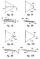
- Figure 7A is a partially schematic, plan view of a projection 725 carrying a flow injection passage 726 in accordance with another embodiment of the invention.
- Figure 7B is a partially schematic, cross-sectional illustration of the projection 725 shown in Figure 7A .
- the projection 725 includes a flow injection passage 726 having a passage aperture 727 that is offset outwardly away from an inner surface 732 of the projection 725.
- An aerodynamic fairing blends the external surfaces of the flow injection passage 726 with those of the projection 725,
- the passage aperture 727 is offset by a distance O outwardly from the inner surface 732, with the value selected for the distance O depending upon the size of the projection 725 and the passage aperture 727, as well as expected operating conditions for the associated nozzle. It is expected that offsetting the passage aperture 727 outwardly away from the shear layer emerging from the nozzle at the projections 725 will aid in decreasing the shear stress near the tip of the projection 725 and/or add to the axial vorticity of the flow directed aft from the projection 725.
- Figures 8A-8B illustrate a plan view and cross-sectional view, respectively, of a projection 825 that injects flow in accordance with another embodiment of the invention.
- the projection 825 includes an injection chamber 826 in fluid communication with a passage aperture 827.
- the injection chamber 826 further includes a membrane 841 or other actuatable device (e.g., a piston) that drives flow inwardly and outwardly through the passage aperture 827.
- a membrane 841 or other actuatable device e.g., a piston
- this arrangement produces pulses of fluid flow at the passage aperture 827. It is expected that this arrangement will have a beneficial effect on noise reduction via an increase in axial vorticity and/or a decrease in shear stress near the tip of the projection 825.
- An additional expected added advantage of this arrangement is that it may be simple and/or energy efficient to implement.
- the axial vorticity and/or shear stress levels are beneficially affected by a combination of introduced flow and projections arranged at the nozzle exit.
- the beneficial effect provided by the projections can be enhanced by devices that need not include flow injection. Representative devices are described in further detail below with reference to Figures 9A-10B .
- Figures 9A and 9B illustrate a plan view and cross-sectional view, respectively, of a projection 925 that includes a mixing enhancement device 950 positioned toward the tip 930 in accordance with an embodiment of the invention.
- the mixing enhancement device 950 has an elongated pin-type configuration extending aft from the tip.
- the mixing enhancement device 950 is also oriented inwardly relative to an inner surface 932 of the projection 925.
- the mixing enhancement device is expected to add to the axial vorticity provided by the projection 925 alone (e.g., by operating as a vortex generator), and/or reduce shear stress near the tip 930 of the projection 925.
- Figures 10A and 10B illustrate a plan view and cross-sectional view, respectively, of a projection 1025 that includes a mixing enhancement device 1050 configured in accordance with another embodiment of the invention.
- the mixing enhancement device 1050 also projects aft of the tip 1030 and is canted inwardly relative to an inner surface 1032 of the projection 1025.
- the mixing enhancement device 1050 is blended or at least partially blended into the external contours of the projection 1025.
- each projection can include more than one flow passage, and/or each flow passage can include more than one passage aperture.
- the passage apertures can be located flush with the tips of the corresponding projections, rather than extending downstream from the tips. Aspects- of the invention described in ⁇ the context of particular embodiments may be combined or eliminated in other embodiments.
- the mixing enhancement devices and projections may be provided at one or both of the core flow exit and the fan flow exit.
- the mixing enhancement devices and/or projections may have characteristics that vary In a circumferential direction around the nozzle.
Description
- The present disclosure is directed generally toward systems and methods for reducing noise (e.g., broadband noise) from jet engines, including via nozzles having chevrons or other projections augmented with proximate injected flows, and/or other mixing enhancement arrangements.
- Aircraft manufacturers are under continual pressure to reduce the noise produced by aircraft in order to satisfy increasingly stringent noise certification rules. Aircraft engines are a major contributor to overall aircraft noise. Accordingly, aircraft engines in particular have been the target of manufacturers' noise reduction efforts. Aircraft engines have been made significantly quieter as a result of advanced high bypass ratio engines. These engines derive a significant fraction of their total thrust not directly from jet exhaust, but from bypass air which is propelled around the core of the engine by an engine-driven forwardly mounted fan. While this approach has significantly reduced aircraft noise when compared with pure turbojet engines and low bypass ratio engines, engine and aircraft federal regulations nevertheless continue to require further engine noise reductions.
- Several techniques have been used to reduce engine exhaust noise. One approach to reducing engine noise is to tailor the amount of mixing between the high velocity gasses exiting the engine, and the surrounding freestream air. A particular technique includes forming "chevrons" at the nozzle exit. Chevrons generally include serrations at the nozzle lip, typically triangular in shape and having some curvature in the lengthwise direction, which slightly immerses them in the adjacent flow. The chevrons can project either inwardly or outwardly, by an amount that is on the order of the upstream boundary layer thickness on the inner or outer surface, respectively. The chevrons can be located at the trailing edge of the nozzle core flow duct (through which the engine core flow is directed), and/or the trailing edge of the fan flow duct, which is arranged annularly around the core flow duct, and through which the fan bypass air passes. The chevrons typically reduce the low-frequency noise by tailoring the rate at which the nozzle flow streams mix with the surrounding freestream air at the length scale of the nozzle diameter. Another technique, which may produce a similar noise reduction is to apply high pressure fluid jets (e.g., microjets) at or near the nozzle exit. While the foregoing approaches have resulted in appreciable noise reduction compared with nozzles that do not include chevrons or fluid injection, further noise reduction is desired to meet community noise standards, and to reduce cabin noise.
-
EP 1580 418 describes a gas turbine engine in which a plurality of tubes extend approximately one quarter of the way across a chevron for discharging air into the core engine. - In accordance with an aspect of the present invention there is provided a method and aircraft system according to the accompanying claims.
- The following summary is provided for the benefit of the reader only, and is not intended to limit in any way the invention as set forth by the claims. Particular aspects of the disclosure are directed to jet engine nozzles that include both trailing edge projections (e.g., chevrons), and proximately-located flow injection apertures, along with associated systems and methods. One method for controlling aircraft engine nozzle flow includes generating a first flow of gas with a jet engine and delivering the first flow through a nozzle having a trailing edge perimeter that includes multiple projections (e.g., chevrons) extending in an aft direction. The method further includes injecting a pressurized second flow of fluid into the first flow at least proximate to the projections. The projections have a generally triangular shape with a tip region positioned aft of a base region. The second flow is injected at a position axially aligned with and at a position downstream of the tip region in a streamwise direction. In still a further particular aspect, the second flow can be changed or halted based at least in part on an engine operating parameter, an aircraft flight condition, or both. For example, the second flow can be reduced or halted when the aircraft is at a cruise flight condition. In other aspects, the second flow can be varied (e.g., pulsed).
- Also disclosed but not claimed, is a method for making an aircraft nozzle system. One such method is applied to a nozzle having an exit with an exit perimeter shape that varies in a circumferential direction, and includes identifying target locations around the nozzle exit perimeter where turbulent kinetic energy production levels of jet flow at the nozzle exit are expected to be higher than an average of turbulent kinetic energy production levels around the perimeter. The method can further include positioning mixing enhancement devices (e.g., vortex generators, elongated extensions, and/or fluid injection apertures) at the target locations. In a particular aspect, the nozzle includes projections at the exit perimeter, the projections having a generally triangular shape with a tip positioned aft of a base. Positioning the mixing enhancement devices includes positioning individual flow injection apertures to be axially aligned with corresponding projection tips in a streamwise direction, with the apertures located aft of the corresponding tips. The apertures may be angled inwardly at an acute angle relative to the corresponding tips.
- An alternative method includes generating a flow of gas with a jet engine and delivering the flow through a nozzle having a trailing edge perimeter including multiple projections extending in an aft direction. The method still further includes increasing flow vorticity, decreasing shear stress, or both adding to vorticity and decreasing shear stress at locations proximate to the projections. In still further aspects, the flow vorticity is increased and/or the shear stress is decreased at tip regions of the projections via mixing enhancement devices. The mixing enhancement devices can include vortex generators, elongated extensions, and/or fluid injection ports.
- Still another aspect is directed to an aircraft system that includes a jet engine exhaust nozzle having an exit aperture with a perimeter that includes multiple projections extending in an aft direction. The system further includes multiple flow injection passages having apertures positioned at least proximate to the projections, with the flow injection passages being coupled to a source of pressurized gas.
- In further particular aspects, the system can also include at least one valve coupled to at least one of the flow injection passages to control flow through the at least one passage. The system can further include a controller operatively coupled to the at least one valve, with the controller programmed to receive input corresponding to an engine operating condition, a flight condition, or both. The controller is also programmed to direct the valve based at least in part on the input.
- An aircraft system that includes a jet engine nozzle having an exit aperture with a perimeter that includes multiple projections extending in an aft direction. The system further includes mixing enhancement devices carried by the projections, with the mixing enhancement devices being positioned to increase vorticity, decrease shear stress, or both increase vorticity and decrease shear
stress at locations proximate to the projections. The mixing enhancement devices include flow injection passages having apertures positioned at least proximate to the projections and flow injection passages coupled to a source of pressurized gas. The projections are generally triangular in shape with a tip positioned aft of a base, and the mixing enhancement devices include elongated extensions extending aft from the tip of the projection. The individual apertures are axially aligned with corresponding tip regions in a streamwise direction and the individual apertures are positioned aft of the corresponding tip region. -
-
Figure 1 illustrates an aircraft having nozzles configured in accordance with an embodiment of the invention. -
Figure 2 illustrates a nozzle having projections and flow injection passages configured in accordance with an embodiment of the invention. -
Figure 3 is an enlarged plan view of a portion of a nozzle having projections and flow injection passages in accordance with an embodiment of the invention. -
Figure 4 is a partially schematic, cross-sectional side view of a nozzle projection and associated flow injection passage, along with control devices configured in accordance with an embodiment of the invention. -
Figure 5 is a graph illustrating test data comparing nozzles with and without projections and injected flow in accordance with an embodiment of the invention. -
Figure 6 is a partially schematic illustration of a nozzle positioned proximate to an aircraft fuselage in accordance with another embodiment of the invention. -
Figures 7A-10B illustrate nozzle projections with noise attenuation capabilities enhanced in accordance with further embodiments of the invention. - Aspects of the present disclosure are directed to jet engine nozzles with chevrons or other projections, and mixing enhancement devices, along with associated systems and methods. Specific details of certain embodiments are described below with reference to
Figures 1-10B . Several details of structures or processes that are well-known and often associated with such systems and processes are not set forth in the following description for purposes o.f brevity. Moreover, although the following disclosure sets forth several embodiments of different aspects of the invention, several other embodiments of the invention can have different configurations or different components than those described in this section. -
Figure 1 is an illustration of a commercialjet transport aircraft 100 havingwings 102, afuselage 101, and apropulsion system 103. The illustratedpropulsion system 103 includes twoengines 106 carried by thewings 102. Eachengine 106 is housed in anacelle 104, which includes aninlet 105 and anozzle 120, Thenozzles 120 include both aft-extending projections and injected flow or other mixing enhancement arrangements, discussed in greater detail below, that reduce the noise generated by theengines 106. The noise reduction achieved by these features may be applied to engines carried in the configuration shown inFigure 1 , or, alternatively, may be applied to engines carried in accordance with other configurations, including those discussed later with reference toFigure 6 . -
Figure 2 is an enlarged side elevation view of thenozzle 120 shown inFigure 1 , configured in accordance with an embodiment of the invention. Thenozzle 120 can include acore flow path 122 that carries engine exhaust products, and afan flow path 121 disposed annularly around thecore flow path 122 for conveying bypass fan flow air. Thecore flow path 122 terminates at acore flow exit 124, and thefan flow path 121 terminates at afan flow exit 123. Either or both of theexits projections 125, having a "chevron" shape or another shape that is arranged to enhance mixing between the gas streams merging at the corresponding exit. For purposes of illustration, thenozzle 120 is shown with bothfan flow projections 125a andcore flow projections 125b, but in particular installations, one or the other of these sets ofprojections projections 125 can include a correspondingmixing enhancement device 150. In a particular arrangement, the mixingenhancement device 150 includes a flow injection passage 126 (a portion of which is shown in hidden lines inFigure 2 ) having apassage aperture 127. Theflow injection passages 126 carry high pressure fluid (e.g., a gas, such as air, or a liquid) and are oriented in a generally aftward direction proximate to theprojections 125. As is discussed in greater detail later, the combination of theprojections 125 and the high pressure flow introduced by the flow injection passages 126 (or other mixing enhancement device) is expected to reduce engine noise by an amount greater than that achievable with either projections or flow injection alone. Mixing enhancement devices that include injected flows are described further below with reference toFigures 3-8B , and other mixing enhancement devices are described later with reference toFigures 9A-10B . -
Figure 3 is an enlarged plan view of a portion of thenozzle 120 Illustratingrepresentative projections 125 configured in accordance with an embodiment of the invention. In this particular embodiment, theprojections 125 have a generally chevron or triangular shape, with atip region 128 positioned aft of abase region 129. Thetip region 128 of eachprojection 125 terminates at anaft-most tip 130. In a particular aspect of this embodiment, theflow injection passages 126 and the associatedpassage apertures 127 are axially aligned (in a streamwise direction) with thetip region 128. It is believed that this location for thepassage apertures 127 will improve the noise reduction capability of thenozzle 120 when compared with other locations for thepassage apertures 127. In particular, it is believed that the turbulent kinetic energy production of the nozzle flow adjacent to theprojections 125 is higher near thetips 130 than near thebase regions 129. It is further believed that the turbulent kinetic energy production levels are reduced by the introduction of high pressure, microjet injected flow. Accordingly, thepassage aperture 127 can be deliberately positioned at or near thetip 130 to compensate for the expected relatively high turbulent kinetic energy production level at this location. It is further expected that this arrangement will reduce sound levels below the levels achievable with theprojections 125 alone. - As is also shown in
Figure 3 ,individual passage apertures 127 are positioned aft of thecorresponding tips 130. In a particular embodiment, thepassage apertures 127 are located just aft oftips 130. For example, eachpassage aperture 127 can be located downstream of thecorresponding tip 130 by a distance of about 20% of the axial length of theprojection 125. In other arrangement (not forming part of the claimed subject-matter), thepassage aperture 127 can be located at thetip 130, or just upstream of thetip 130, though it is expected that the downstream location will produce better noise reduction.
Accordingly, in still further embodiments, thepassage aperture 127 can be positioned downstream of thecorresponding tip 130 by a distance of up to about one nozzle diameter (e.g., the diameter of thenozzle 120 at the perimeter location from which theprojection 125 extends). For purposes of illustration, a singleflow injection aperture 127 is shown for anindividual projection 125; in other embodiments, individual projections includemultiple apertures 127 side-by-side near thetip 130. This arrangement can reduce the size of eachaperture 127 and associatedflow passage 126, without reducing the injected mass flow. Theapertures 127 can be oriented to have a zero azimuthal angle Z (as shown inFigure 3 ) or a non-zero azimuthal angle in other embodiments. The azimuthal angle Z may be non-zero when theprojection 125 includes asingle aperture 127, and/or when theprojection 125 includesmultiple apertures 127. In the latter case, theapertures 127 on a givenprojection 125 may be directed toward each other or away from each other. - In addition to housing the
flow injection passages 126, theprojections 125 may, in at least some embodiments, also be movable relative to the rest of thenozzle 120. For example, theprojections 125 can pivot along ahinge line 131 relative to the rest of thenozzle 120 to alter the degree to which eachprojection 125 is immersed in (e.g., inclined relative to) the upstream nozzle flow. Theprojections 125 can be formed from a resilient flexible material and, when actuated, form a continuously curved, immersed surface, rather than a surface with a discontinuity at thehinge line 131. As will be discussed below with reference toFigure 4 , the noise reduction and overall efficiency of thenozzle 120 can be adjusted by adjusting the flow through theflow injection passages 126, optionally in combination with adjusting the orientation of theprojections 125. -
Figure 4 is a partially schematic, side cross-sectional view of a portion of thenozzle 120, one of theprojections 125, and the associatedflow injection passage 126. Theflow injection passage 126 is coupled to asource 140 of pressurized gas. Thesource 140 can provide compressed air or another gas (e.g., exhaust gas) to theflow injection passage 126. In a particular embodiment, thesource 140 can include the engine compressor, which provides compressed air to theflow injection passage 126 via a bleed air port. In other embodiments, high pressure air can be provided by other sources, e.g., an aircraft auxiliary power unit (APU). - As discussed above, the
passage aperture 127 is axially aligned in a streamwise direction with thetip 130 of theprojection 125. As is shown inFigure 4 , the flow axis of theflow injection passage 126 at thepassage aperture 127 can be inclined by an angle A relative to the adjacent flow direction of gas passing along aninner surface 132 of the nozzle 120 (indicated by arrow G). The inclination angle A can be an acute angle having a selected value of between 0° and ±90°. In a particular embodiment, the inclination angle A is about 60° relative to the internal gas flow direction G. The particular inclination angle A selected for thepassage aperture 127 can have other values in other embodiments, and can be selected for a particular installation based on factors that can include the nozzle pressure ratio, particular nozzle geometry features, and the shape of theprojection 125, among other factors. For example, when theprojection 125 is immersed inwardly (as shown inFigure 4 ), angle A can have a positive value. In a multi-stream installation (e.g., with a bypass flow stream located annularly outwardly from a core flow stream), theprojection 125 may be located between the two streams and immersed in an outward direction into the bypass flow stream. In such an instance, angle A may have a negative value. In a particular embodiment, thepassage aperture 127 is round. In other embodiments, the shape and/or size of thepassage aperture 127 can be different, depending, for example, upon the size of the engine and nozzle, and/or installation details. - Aspects of the
projections 125 and/or theflow injection passages 126 may be selectively changed and/or otherwise controlled during operation. For example, when theprojections 125 are movable relative to the rest of thenozzle 120, thenozzle 120 can include one ormore actuators 134 that are coupled to theprojections 125 to rotate them (as indicated by arrow I) in a manner that alters the degree of immersion for eachprojection 125. Theprojections 125 can be controlled so as to move independently of each other, or all together. - To accommodate the relative motion of the
projections 125, and also to accommodate other movable features of the nozzle 120 (including but not limited to thrust reverser features), at least some portions of theflow injection passages 126 can include flexible tubing or other adaptable, conformable and/or resilient structures. Theflow injection passages 126 may also be coupled to one ormore valves 135 to control the flow through eachpassage 126 and the associatedpassage aperture 127. - A
controller 136 can be operatively coupled to thevalves 135 and theactuator 134 to direct the operation of these components during flight. Thecontroller 136 can receive engine inputs 137 (e.g., engine thrust levels), flight condition inputs 138 (e.g., indications of the current and/or upcoming flight condition, such as takeoff, landing, cruise, or others), and/or other inputs 139 (e.g., pilot inputs). Based on the inputs 137-139, thecontroller 136 can direct the motion of theprojections 125 and/or the amount of flow passing through theflow passages 126. For example, at conditions for which noise reduction is of relatively high importance, thecontroller 136 can direct the maximum (or a relatively high) amount of flow through theflow passages 126, and, optionally, can move theprojections 125 to the immersion angle expected to reduce noise by the greatest amount. Such a condition may occur during takeoff when the engine is set at or close to its maximum thrust level. At other conditions, including but not limited to cruise conditions, the need to operate the engine efficiently may outweigh the need to reduce engine noise beyond a threshold level. Accordingly, thecontroller 136 can reduce or halt the flow of pressurized air through theflow passages 126, and can adjust the immersion angle I of theprojections 125 to be at or close to zero. In a particular embodiment, thecontroller 136 can include a feedback loop to control exhaust noise. For example, theother inputs 139 can include inputs from a microphone, pressure sensor or other sensor that directly or indirectly detects engine exhaust noise levels. Thecontroller 136 then adjusts the operating parameters for theprojections 125 and/or flowpassages 126 to provide the desired (e.g., optimal) level of noise reduction. At any of the foregoing conditions, the flow can be varied, e.g., pulsed or otherwise directed in a time-varying manner. The foregoing parameters can be adjusted automatically based on the received inputs, and/or can be overridden, adjusted, or otherwise manipulated by the pilot. Thecontroller 136 can accordingly include a computer having a processor, memory, input/output capabilities, and a computer-readable medium having computer-executable instructions. The function of the computer can be integrated with existing aircraft computers, or the computer can include a standalone unit that communicates with other aircraft systems. - It is typically desirable to inject the minimum amount of flow determined necessary to provide the desired noise reduction, so as to reduce the impact on engine efficiency associated with removing flow from the engine. In general, it is expected that the amount of injected flow can be less than or equal to 5% of the overall engine mass flow. For example, in particular embodiments, it is expected that the amount of injected flow can be about 1% or less (e.g., 0.5%) of the overall engine mass flow at takeoff conditions. As discussed above, the amount of injected flow can be reduced or eliminated at other engine settings and/or flight conditions.
- One feature of at least some of the foregoing embodiments is that the flow of fluid (e.g., a gas or a liquid) through the
flow passages 126 can be adjusted in a manner that depends upon the relative need for noise reduction and the relative need for efficient engine operation. While this arrangement can be supplemented bymovable projections 125, it may also be easier to implement than movable projections, and can accordingly be used in lieu ofmovable projections 125. An advantage of this arrangement is that it can allow the operator to control engine noise reduction and efficiency with a relatively simple valving arrangement (e.g., the valve 135). - Another feature of at least some of the foregoing embodiments is that the flow provided by the
flow passages 126 is expected to produce a significant reduction in noise when compared with the noise reduction achievable by the use of theprojections 125 alone. Accordingly, the injected flow can be used in combination with theprojections 125 to achieve an overall lower noise level. It is expected that the noise reduction can be achieved for broadband noise, shock cell noise, noise heard on the ground (e.g., community noise, particularly on takeoff), and/or noise heard in the aircraft (e.g., cabin noise, particularly during cruise). Alternatively, the flow injection can be used to reduce the number or change the configuration (e.g., reduce the immersion) of theprojections 125, while producing a noise level reduction equal to that of a larger number or different configuration of projections alone. As a result, the injected flow can in some cases reduce the overall weight of the aircraft by reducing the number of theprojections 125, and/or can improve the efficiency of the aircraft. - Still another feature of at least some of the foregoing embodiments is that the injected flow can be provided at locations that compensate for limitations associated with the projections alone. For example, test data indicate that the projections alone produce high shear and/or low (or zero) axial vorticity at the tip regions. Both of these characteristics can limit the noise reduction capabilities of the projections. Placing the injected flow at the tip regions is expected to reduce shear and/or increase axial vorticity in a manner that increases overall noise reduction.
-
Figure 5 is a graph illustrating measured noise levels for three different nozzles, as a function of angular position relative to the nozzle at a radius of 100 nozzle diameters. Accordingly, 90° on the x-axis corresponds to a position longitudinally aligned with the nozzle and laterally offset from the nozzle by 100 nozzle diameters, and 180° corresponds to a position laterally aligned with the nozzle exit, and axially (longitudinally) offset by 100 nozzle diameters downstream of the nozzle exit. Line 140a illustrates data corresponding to a standard circular nozzle,line 140b illustrates data corresponding to a nozzle having 18 conventional chevrons with a relatively mild degree of immersion, andnozzle 140c corresponds to a circular nozzle having a uniform circular exit perimeter and aft-directed flow injection exiting from the perimeter.Line 140d corresponds to a nozzle having 18 chevron shaped projections in combination with flow injected in a manner generally similar to that described above with reference toFigures 3 and 4 . These acoustic test data indicate that the noise reduction benefit associated with a nozzle having both projections and injected flow is significantly greater than that realized by a nozzle having projections alone or flow injection alone. For example, at many of the angular locations shown inFigure 5 , the noise reduction increases from about 1dB to about 2dB. -
Figure 6 is a partially schematic, rear elevation view of anengine nacelle 604 and associatednozzle 620 mounted adjacent to theaircraft fuselage 101 in accordance with another embodiment of the invention. In this embodiment, thenozzle 620 can include projections 625 (shown asfan flow projections 625a andcore flow projections 625b), some or all of which includeflow injection passages 627 generally similar to those described above. In this embodiment, the projections 625 and flowpassages 627 can be sized and configured to provide noise reduction not only for observers on the ground, but also for passengers within thefuselage 101. In other embodiments, thenacelle 604 can have other locations relative to thefuselage 101 and/or the aircraft wings, with the projections and associated flow passages tailored accordingly in a suitable manner. - The foregoing systems can reduce nozzle noise levels by adding to the axial vorticity generated by the projections and/or by decreasing the shear stress near the tips of the projections. In other embodiments, the systems can include different arrangements that achieve noise reduction by one or both of the foregoing mechanisms. Representative embodiments are described below with reference to
Figures 7A-10B . -
Figure 7A is a partially schematic, plan view of aprojection 725 carrying aflow injection passage 726 in accordance with another embodiment of the invention.Figure 7B is a partially schematic, cross-sectional illustration of theprojection 725 shown inFigure 7A . Referring now toFigures 7A and 7B , theprojection 725 includes aflow injection passage 726 having apassage aperture 727 that is offset outwardly away from aninner surface 732 of theprojection 725. An aerodynamic fairing (not shown inFigures 7A-7B ) blends the external surfaces of theflow injection passage 726 with those of theprojection 725, In a particular embodiment, thepassage aperture 727 is offset by a distance O outwardly from theinner surface 732, with the value selected for the distance O depending upon the size of theprojection 725 and thepassage aperture 727, as well as expected operating conditions for the associated nozzle. It is expected that offsetting thepassage aperture 727 outwardly away from the shear layer emerging from the nozzle at theprojections 725 will aid in decreasing the shear stress near the tip of theprojection 725 and/or add to the axial vorticity of the flow directed aft from theprojection 725. -
Figures 8A-8B illustrate a plan view and cross-sectional view, respectively, of aprojection 825 that injects flow in accordance with another embodiment of the invention. In this particular arrangement, theprojection 825 includes aninjection chamber 826 in fluid communication with apassage aperture 827. Theinjection chamber 826 further includes amembrane 841 or other actuatable device (e.g., a piston) that drives flow inwardly and outwardly through thepassage aperture 827. Accordingly, rather than providing a continuous flow of fluid, this arrangement produces pulses of fluid flow at thepassage aperture 827. It is expected that this arrangement will have a beneficial effect on noise reduction via an increase in axial vorticity and/or a decrease in shear stress near the tip of theprojection 825. An additional expected added advantage of this arrangement is that it may be simple and/or energy efficient to implement. - The axial vorticity and/or shear stress levels are beneficially affected by a combination of introduced flow and projections arranged at the nozzle exit. In other embodiments, the beneficial effect provided by the projections can be enhanced by devices that need not include flow injection. Representative devices are described in further detail below with reference to
Figures 9A-10B . -
Figures 9A and 9B illustrate a plan view and cross-sectional view, respectively, of aprojection 925 that includes a mixingenhancement device 950 positioned toward thetip 930 in accordance with an embodiment of the invention. In this particular arrangement, the mixingenhancement device 950 has an elongated pin-type configuration extending aft from the tip. The mixingenhancement device 950 is also oriented inwardly relative to aninner surface 932 of theprojection 925. The mixing enhancement device is expected to add to the axial vorticity provided by theprojection 925 alone (e.g., by operating as a vortex generator), and/or reduce shear stress near thetip 930 of theprojection 925. -
Figures 10A and 10B illustrate a plan view and cross-sectional view, respectively, of aprojection 1025 that includes a mixingenhancement device 1050 configured in accordance with another embodiment of the invention. In this arrangement, the mixingenhancement device 1050 also projects aft of thetip 1030 and is canted inwardly relative to aninner surface 1032 of theprojection 1025. The mixingenhancement device 1050 is blended or at least partially blended into the external contours of theprojection 1025. - From the foregoing, it will be appreciated that specific embodiments of the invention have been described herein for purposes of illustration, but that various modifications may be made without deviating from the invention. Each projection can include more than one flow passage, and/or each flow passage can include more than one passage aperture. In particular arrangements, the passage apertures can be located flush with the tips of the corresponding projections, rather than extending downstream from the tips. Aspects- of the invention described in· the context of particular embodiments may be combined or eliminated in other embodiments. For example, the mixing enhancement devices and projections may be provided at one or both of the core flow exit and the fan flow exit. The mixing enhancement devices and/or projections may have characteristics that vary In a circumferential direction around the nozzle. Further, while advantages associated with certain embodiments of the invention have been described in the context of those embodiments, other embodiments may also exhibit such advantages, and not all embodiments need necessarily exhibit such advantages to fall within -the scope of the invention.
Accordingly, the invention is not limited, except as by the appended claims.
Claims (13)
- A method for controlling aircraft engine nozzle flow, comprising:generating a first flow of gas with a jet engine (106);delivering the first flow through a nozzle (120) having a trailing edge perimeter including multiple projections (125) extending in an aft direction, wherein the projections (125) have a generally triangular shape with a tip region (128) positioned aft of a base region (129); anddirecting a second flow of fluid into the first flow at least proximate to the projections (125), characterised in that:injecting the second flow includes injecting the second flow in a streamwise direction at a position axially aligned with the tip region (128); andinjecting the second flow includes injecting the second flow at a position downstream of the tip region.
- The method of claim 1 wherein injecting the second flow includes directing the second flow at a non-zero acute angle relative to a flow direction of the first flow.
- The method of claim 1, further comprising changing, pulsing, or halting injection of the second flow based at least in part on an engine operating parameter, an aircraft flight condition, or both.
- The method of claim 1, further comprising moving the projections (125) relative to the engine based at least in part on an engine operating parameter, an aircraft flight condition, or both.
- The method of claim 1 wherein the first flow produces turbulent kinetic energy production levels of jet flow at the trailing edge perimeter that vary around the perimeter relative to an average value, and wherein injecting the second flow includes injecting the second flow at a circumferential location where the turbulent kinetic energy production levels are higher than the average value.
- The method of claim 1 wherein injecting the second flow includes injecting the second flow into a core flow of the engine.
- The method of claim 1 wherein injecting the second flow includes injecting the second flow into a bypass flow of the engine.
- An aircraft system, comprising:a jet engine exhaust nozzle (120) having an exit aperture, the exit aperture having a perimeter, the perimeter including multiple projections (125) extending in an aft direction, wherein the projections (125) have a generally triangular shape with a tip region (128) positioned aft of a base region (129); andmultiple flow injection passages (126) having apertures (127) positioned at least proximate to the projections (125), the flow injection passages (126) being coupled to a source (140) of pressurized gas, characterised in that:
individual apertures (127) are axially aligned with corresponding tip regions (128) in a streamwise direction and the individual apertures (127) are positioned aft of the corresponding tip region (128). - The system of claim 8 wherein individual apertures (127) are positioned aft of the corresponding tip regions by a distance of up to about one nozzle diameter.
- The system of claim 8 wherein the apertures (127) are canted inwardly relative to the corresponding tips at an acute angle.
- The system of claim 8 wherein individual projections (125) are movable between a first position in which the projections are inclined relative to the adjacent nozzle flow path by a first amount, and second position in which the projections are inclined relative to the adjacent nozzle flow path by a second amount less than the first amount.
- The system of claim 8, further comprising:at least one valve (135) coupled to at least one of the flow injection passages (126) to control flow through the at least one flow injection passage; anda controller (136) operatively coupled to the at least one valve (135), the controller (136) being programmed to receive input corresponding to an engine operating condition, a flight condition, or both, and, based at least in part on the input, direct the valve.
- The system of claim 8 wherein the projections (125) are positioned between a core flow path (122) of the nozzle and a bypass flow path (121) of the nozzle.
Applications Claiming Priority (2)
| Application Number | Priority Date | Filing Date | Title |
|---|---|---|---|
| US11/707,217 US7966826B2 (en) | 2007-02-14 | 2007-02-14 | Systems and methods for reducing noise from jet engine exhaust |
| PCT/US2008/052527 WO2008100712A2 (en) | 2007-02-14 | 2008-01-30 | Systems and methods for reducing noise from jet engine exhaust |
Publications (2)
| Publication Number | Publication Date |
|---|---|
| EP2118475A2 EP2118475A2 (en) | 2009-11-18 |
| EP2118475B1 true EP2118475B1 (en) | 2018-09-26 |
Family
ID=39690725
Family Applications (1)
| Application Number | Title | Priority Date | Filing Date |
|---|---|---|---|
| EP08728611.8A Active EP2118475B1 (en) | 2007-02-14 | 2008-01-30 | Systems and methods for reducing noise from jet engine exhaust |
Country Status (5)
| Country | Link |
|---|---|
| US (1) | US7966826B2 (en) |
| EP (1) | EP2118475B1 (en) |
| JP (2) | JP5084844B2 (en) |
| CN (1) | CN101589217B (en) |
| WO (1) | WO2008100712A2 (en) |
Families Citing this family (36)
| Publication number | Priority date | Publication date | Assignee | Title |
|---|---|---|---|---|
| EP2074319B1 (en) * | 2006-10-12 | 2012-08-15 | United Technologies Corporation | Gas turbine engine with a variable exit area fan nozzle, nacelle assembly of such a engine, and corresponding operating method |
| US7966826B2 (en) * | 2007-02-14 | 2011-06-28 | The Boeing Company | Systems and methods for reducing noise from jet engine exhaust |
| US7963099B2 (en) * | 2007-05-21 | 2011-06-21 | General Electric Company | Fluted chevron exhaust nozzle |
| US7926285B2 (en) * | 2007-07-18 | 2011-04-19 | General Electric Company | Modular chevron exhaust nozzle |
| US8371806B2 (en) * | 2007-10-03 | 2013-02-12 | United Technologies Corporation | Gas turbine engine having core auxiliary duct passage |
| FR2924168B1 (en) * | 2007-11-23 | 2015-09-04 | Snecma | BLOWER TUBE WITH ADJUSTABLE SECTION |
| JP4862961B2 (en) * | 2008-02-25 | 2012-01-25 | 株式会社Ihi | Noise reduction device and jet propulsion system |
| FR2929337B1 (en) * | 2008-03-31 | 2012-06-01 | Airbus France | SECONDARY JET DEVICE FOR REDUCING NOISE GENERATED BY AN AIRCRAFT REACTOR |
| FR2929335B1 (en) * | 2008-03-31 | 2012-06-01 | Airbus France | NOISE REDUCTION DEVICE GENERATED BY AN AIRCRAFT REACTOR WITH FLUID JETS OF THE SAME ORIENTATION |
| FR2929334B1 (en) * | 2008-03-31 | 2012-06-01 | Airbus France | DEVICE FOR REDUCING NOISE GENERATION BY AIRCRAFT REACTOR WITH BLEED FLUID CONDUITS |
| FR2929336B1 (en) * | 2008-03-31 | 2012-06-01 | Airbus France | JET DEVICE NOISE REDUCTION PLATES GENERATED BY AN AIRCRAFT REACTOR |
| US8087250B2 (en) * | 2008-06-26 | 2012-01-03 | General Electric Company | Duplex tab exhaust nozzle |
| FR2934875B1 (en) * | 2008-08-06 | 2010-08-13 | Aircelle Sa | NACELLE OF TURBOREACTEUR MOBILE CHEVRONS. |
| US20100083632A1 (en) * | 2008-10-08 | 2010-04-08 | Searete Llc, A Limited Liability Corporation Of The State Of Delaware | Hybrid propulsive engine including at least one independently rotatable compressor rotor |
| US8109073B2 (en) * | 2008-10-08 | 2012-02-07 | The Invention Science Fund I, Llc | Hybrid propulsive engine including at least one independently rotatable compressor stator |
| US8596036B2 (en) * | 2008-10-08 | 2013-12-03 | The Invention Science Fund I Llc | Hybrid propulsive engine including at least one independently rotatable compressor rotor |
| US20100126178A1 (en) * | 2008-10-08 | 2010-05-27 | Searete Llc, A Limited Liability Corporation Of The State Of Delaware | Hybrid propulsive engine including at least one independently rotatable turbine stator |
| JP5481946B2 (en) * | 2009-06-05 | 2014-04-23 | 株式会社Ihi | Noise reduction device |
| EP2495423B1 (en) * | 2009-10-28 | 2016-05-18 | IHI Corporation | Noise reduction device |
| US9528468B2 (en) * | 2009-10-28 | 2016-12-27 | Ihi Corporation | Noise reduction system |
| CN102822492B (en) * | 2010-04-09 | 2015-08-12 | 株式会社Ihi | Spout nozzles and jet engine |
| FR2960028B1 (en) * | 2010-05-12 | 2016-07-15 | Snecma | DEVICE FOR ATTENUATING THE NOISE EMITTED BY THE JET OF A PROPULSION ENGINE OF AN AIRCRAFT. |
| JP5842211B2 (en) * | 2011-01-21 | 2016-01-13 | 国立研究開発法人宇宙航空研究開発機構 | Aerodynamic noise reduction device |
| CN102167162A (en) * | 2011-03-10 | 2011-08-31 | 洪瑞庆 | Ultra-high pressure fluid jetting power track transferring system and method for aircraft |
| DE102012109647B4 (en) | 2012-10-10 | 2015-09-03 | Airbus Defence and Space GmbH | Aircraft with means for pulsating a gas into the exhaust nozzle |
| DE102012219541A1 (en) | 2012-10-25 | 2014-04-30 | Deutsches Zentrum für Luft- und Raumfahrt e.V. | Nozzle e.g. exhaust nozzle of aircraft jet engine, comprises a turbulence and/or swirl-generating structure which projects radially from the nozzle walls to the inside and/or on the outer side of the nozzle walls |
| CN103835810B (en) * | 2012-11-27 | 2017-02-08 | 中航商用航空发动机有限责任公司 | Acoustic liner for air-inlet nacelle of aircraft engine and aircraft engine |
| US9458732B2 (en) | 2013-10-25 | 2016-10-04 | General Electric Company | Transition duct assembly with modified trailing edge in turbine system |
| CN105781791A (en) * | 2016-04-06 | 2016-07-20 | 西北工业大学 | Lobe noise reduction ejector for intensively-mixed pulsation air jet |
| US10611458B2 (en) * | 2017-05-09 | 2020-04-07 | The Boeing Company | Aircraft cabin noise reduction systems and methods |
| US11365704B2 (en) * | 2018-02-27 | 2022-06-21 | New York University In Abu Dhabi Corportion | Directionally targeted jet noise reduction system and method |
| US11440671B2 (en) * | 2019-01-24 | 2022-09-13 | Amazon Technologies, Inc. | Adjustable motor fairings for aerial vehicles |
| CN110454298A (en) * | 2019-07-26 | 2019-11-15 | 中国航发沈阳发动机研究所 | A kind of exhaust apparatus with decrease of noise functions |
| CN112211745A (en) * | 2020-10-13 | 2021-01-12 | 西北工业大学 | Solid rocket engine structure with tail nozzle with special-shaped section |
| US20220195960A1 (en) * | 2020-12-21 | 2022-06-23 | Rohr, Inc. | Gas turbine engine exhaust chevrons |
| CN114856814A (en) * | 2022-05-17 | 2022-08-05 | 中国人民解放军海军工程大学 | Plasma synthetic jet flow vortex generating device for flow control |
Family Cites Families (51)
| Publication number | Priority date | Publication date | Assignee | Title |
|---|---|---|---|---|
| FR2091911B1 (en) * | 1970-04-21 | 1974-03-01 | Snecma | |
| US3648800A (en) | 1970-04-27 | 1972-03-14 | Gen Electric | Coanda expansion exhaust nozzle suppressor |
| FR2126922B1 (en) | 1971-01-20 | 1975-01-17 | Snecma | |
| US4372110A (en) | 1976-02-13 | 1983-02-08 | Nasa | Noise suppressor for turbo fan jet engines |
| US4215536A (en) | 1978-12-26 | 1980-08-05 | The Boeing Company | Gas turbine mixer apparatus |
| GB2104967B (en) | 1981-09-03 | 1985-07-17 | Rolls Royce | Exhaust mixer for turbofan aeroengine |
| US4819425A (en) | 1982-03-18 | 1989-04-11 | The Boeing Company | Primary-secondary ventilated flow mixer nozzle for high bypass turbo fan jet propulsion system |
| GB2146702B (en) | 1983-09-14 | 1987-12-23 | Rolls Royce | Exhaust mixer for turbofan aeroengine |
| GB2149456B (en) | 1983-11-08 | 1987-07-29 | Rolls Royce | Exhaust mixing in turbofan aeroengines |
| GB2207468A (en) | 1987-06-01 | 1989-02-01 | Secr Defence | Vortex silencing in gas turbine engines |
| US5117628A (en) * | 1990-01-25 | 1992-06-02 | General Electric Company | Mixed flow augmentor pre-mixer |
| US5751944A (en) * | 1995-07-28 | 1998-05-12 | Micron Quantum Devices, Inc. | Non-volatile memory system having automatic cycling test function |
| US5884472A (en) | 1995-10-11 | 1999-03-23 | Stage Iii Technologies, L.C. | Alternating lobed mixer/ejector concept suppressor |
| US5924632A (en) | 1996-05-02 | 1999-07-20 | The United States Of America As Represented By The Administrator Of The National Aeronautics And Space Administration | Jet nozzle having centerbody for enhanced exit area mixing |
| US6082635A (en) | 1996-06-12 | 2000-07-04 | The United States Of America As Represented By The Administrator Of The National Aeronautics And Space Administration | Undulated nozzle for enhanced exit area mixing |
| US5947412A (en) | 1997-01-10 | 1999-09-07 | Titan Corporation | Jet engine noise suppressor assembly |
| US6360528B1 (en) | 1997-10-31 | 2002-03-26 | General Electric Company | Chevron exhaust nozzle for a gas turbine engine |
| US6314721B1 (en) | 1998-09-04 | 2001-11-13 | United Technologies Corporation | Tabbed nozzle for jet noise suppression |
| US6612106B2 (en) | 2000-05-05 | 2003-09-02 | The Boeing Company | Segmented mixing device having chevrons for exhaust noise reduction in jet engines |
| EP1322854A4 (en) | 2000-10-02 | 2004-08-04 | Rohr Inc | Apparatus, method and system for gas turbine engine noise reduction |
| US6640537B2 (en) | 2000-12-18 | 2003-11-04 | Pratt & Whitney Canada Corp. | Aero-engine exhaust jet noise reduction assembly |
| US6837456B1 (en) | 2001-01-10 | 2005-01-04 | Florida State University Research Foundation | Microjet based control system |
| GB0105349D0 (en) | 2001-03-03 | 2001-04-18 | Rolls Royce Plc | Gas turbine engine exhaust nozzle |
| US6532729B2 (en) | 2001-05-31 | 2003-03-18 | General Electric Company | Shelf truncated chevron exhaust nozzle for reduction of exhaust noise and infrared (IR) signature |
| EP1438494B1 (en) | 2001-10-23 | 2017-01-04 | THE NORDAM GROUP, Inc. | Confluent variable exhaust nozzle |
| BR0307845B1 (en) | 2002-02-22 | 2012-09-18 | duplex mixer exhaust nozzle. | |
| US6658839B2 (en) | 2002-02-28 | 2003-12-09 | The Boeing Company | Convergent/divergent segmented exhaust nozzle |
| US7293401B2 (en) | 2002-03-20 | 2007-11-13 | The Regents Of The University Of California | Jet engine noise suppressor |
| US6983912B2 (en) | 2002-04-30 | 2006-01-10 | The Boeing Company | Hybrid exhaust heat shield for pylon mounted gas turbine engines |
| US6718752B2 (en) | 2002-05-29 | 2004-04-13 | The Boeing Company | Deployable segmented exhaust nozzle for a jet engine |
| GB0226228D0 (en) | 2002-11-09 | 2002-12-18 | Rolls Royce Plc | Suppression of part of the noise from a gas turbine engine |
| US6969028B2 (en) | 2003-01-22 | 2005-11-29 | The Boeing Company | Scarf nozzle for a jet engine and method of using the same |
| US7010905B2 (en) | 2003-02-21 | 2006-03-14 | The Nordam Group, Inc. | Ventilated confluent exhaust nozzle |
| US6971229B2 (en) | 2003-02-26 | 2005-12-06 | The Nordam Group, Inc. | Confluent exhaust nozzle |
| US7055329B2 (en) | 2003-03-31 | 2006-06-06 | General Electric Company | Method and apparatus for noise attenuation for gas turbine engines using at least one synthetic jet actuator for injecting air |
| FR2855558B1 (en) | 2003-05-28 | 2005-07-15 | Snecma Moteurs | TURBOMACHINE TUBE WITH NOISE REDUCTION |
| US7581692B2 (en) * | 2003-06-30 | 2009-09-01 | General Electric Company | Fluidic chevrons and configurable thermal shield for jet noise reduction |
| FR2857416B1 (en) | 2003-07-09 | 2007-05-25 | Snecma Moteurs | DEVICE FOR REDUCING JET NOISE OF A TURBOMACHINE |
| US7093423B2 (en) | 2004-01-20 | 2006-08-22 | General Electric Company | Methods and apparatus for operating gas turbine engines |
| US7114323B2 (en) | 2004-03-05 | 2006-10-03 | United Technologies Corporation | Jet exhaust noise reduction system and method |
| FR2868131B1 (en) | 2004-03-25 | 2006-06-09 | Airbus France Sas | PRIME TUBE WITH CHEVRONS FOR A DOUBLE FLOW AIRCRAFT AIRCRAFT AND AIRCRAFT COMPRISING SUCH TUYERE |
| US7246481B2 (en) | 2004-03-26 | 2007-07-24 | General Electric Company | Methods and apparatus for operating gas turbine engines |
| GB0505246D0 (en) | 2005-03-15 | 2005-04-20 | Rolls Royce Plc | Engine noise |
| FR2901321B1 (en) * | 2006-05-18 | 2011-08-12 | Aircelle Sa | METHOD FOR HOMOGENIZING AIR FROM TURBOJET OUTPUT TO LOWER GENERATED NOISE |
| US7721551B2 (en) | 2006-06-29 | 2010-05-25 | United Technologies Corporation | Fan variable area nozzle for a gas turbine engine fan nacelle |
| US8157207B2 (en) | 2006-08-09 | 2012-04-17 | The Boeing Company | Jet engine nozzle exit configurations, including projections oriented relative to pylons, and associated systems and methods |
| US7520124B2 (en) | 2006-09-12 | 2009-04-21 | United Technologies Corporation | Asymmetric serrated nozzle for exhaust noise reduction |
| US8015819B2 (en) | 2006-09-29 | 2011-09-13 | The United States Of America As Represented By The Administrator Of The National Aeronautics And Space Administration | Wet active chevron nozzle for controllable jet noise reduction |
| US7870722B2 (en) | 2006-12-06 | 2011-01-18 | The Boeing Company | Systems and methods for passively directing aircraft engine nozzle flows |
| US7966826B2 (en) * | 2007-02-14 | 2011-06-28 | The Boeing Company | Systems and methods for reducing noise from jet engine exhaust |
| FR2929336B1 (en) * | 2008-03-31 | 2012-06-01 | Airbus France | JET DEVICE NOISE REDUCTION PLATES GENERATED BY AN AIRCRAFT REACTOR |
-
2007
- 2007-02-14 US US11/707,217 patent/US7966826B2/en active Active
-
2008
- 2008-01-30 CN CN200880001395XA patent/CN101589217B/en active Active
- 2008-01-30 WO PCT/US2008/052527 patent/WO2008100712A2/en active Application Filing
- 2008-01-30 EP EP08728611.8A patent/EP2118475B1/en active Active
- 2008-01-30 JP JP2009550101A patent/JP5084844B2/en active Active
-
2012
- 2012-04-10 JP JP2012088905A patent/JP5364812B2/en active Active
Non-Patent Citations (1)
| Title |
|---|
| None * |
Also Published As
| Publication number | Publication date |
|---|---|
| JP2012177369A (en) | 2012-09-13 |
| WO2008100712A3 (en) | 2008-11-27 |
| JP5364812B2 (en) | 2013-12-11 |
| CN101589217A (en) | 2009-11-25 |
| JP2010518323A (en) | 2010-05-27 |
| US20090320487A1 (en) | 2009-12-31 |
| US7966826B2 (en) | 2011-06-28 |
| JP5084844B2 (en) | 2012-11-28 |
| WO2008100712A2 (en) | 2008-08-21 |
| EP2118475A2 (en) | 2009-11-18 |
| CN101589217B (en) | 2012-07-04 |
Similar Documents
| Publication | Publication Date | Title |
|---|---|---|
| EP2118475B1 (en) | Systems and methods for reducing noise from jet engine exhaust | |
| US8166768B2 (en) | Systems and methods for passively directing aircraft engine nozzle flows | |
| US7472543B2 (en) | Jet engine noise suppressor | |
| US7055329B2 (en) | Method and apparatus for noise attenuation for gas turbine engines using at least one synthetic jet actuator for injecting air | |
| EP2138696B1 (en) | Gas turbine engine with noise attenuating variable area fan nozzle | |
| US20060283188A1 (en) | Suppression of part of the noise from a gas turbine engine | |
| CA2992931C (en) | Aircraft comprising a rear fairing propulsion system with inlet stator comprising a blowing function | |
| US8015819B2 (en) | Wet active chevron nozzle for controllable jet noise reduction | |
| US7802752B2 (en) | Jet engine noise suppressor | |
| US11884414B2 (en) | Supersonic aircraft turbofan engine | |
| US7412832B2 (en) | Method and apparatus for operating gas turbine engines | |
| GB2540865A (en) | A propulsion assembly for an aircraft having a turbojet with a non-ducted fan and an attachment pylon | |
| CN102893009B (en) | Device for reducing the noise emitted by the jet of an aircraft propulsion engine | |
| EP3470652A1 (en) | Gas turbine engine vortex suppressor | |
| CA2861181A1 (en) | Methods and apparatus for passive thrust vectoring and plume deflection | |
| Papamoschou | Engine cycle and exhaust configuration for quiet supersonic propulsion | |
| US8225592B1 (en) | Microjet noise suppression system for jet engines |
Legal Events
| Date | Code | Title | Description |
|---|---|---|---|
| PUAI | Public reference made under article 153(3) epc to a published international application that has entered the european phase |
Free format text: ORIGINAL CODE: 0009012 |
|
| 17P | Request for examination filed |
Effective date: 20090610 |
|
| AK | Designated contracting states |
Kind code of ref document: A2 Designated state(s): AT BE BG CH CY CZ DE DK EE ES FI FR GB GR HR HU IE IS IT LI LT LU LV MC MT NL NO PL PT RO SE SI SK TR |
|
| 17Q | First examination report despatched |
Effective date: 20091217 |
|
| DAX | Request for extension of the european patent (deleted) | ||
| STAA | Information on the status of an ep patent application or granted ep patent |
Free format text: STATUS: EXAMINATION IS IN PROGRESS |
|
| REG | Reference to a national code |
Ref country code: DE Ref legal event code: R079 Ref document number: 602008057145 Country of ref document: DE Free format text: PREVIOUS MAIN CLASS: F02K0001460000 Ipc: B64D0029020000 |
|
| GRAP | Despatch of communication of intention to grant a patent |
Free format text: ORIGINAL CODE: EPIDOSNIGR1 |
|
| STAA | Information on the status of an ep patent application or granted ep patent |
Free format text: STATUS: GRANT OF PATENT IS INTENDED |
|
| RIC1 | Information provided on ipc code assigned before grant |
Ipc: B64D 29/02 20060101AFI20180314BHEP Ipc: B64D 33/04 20060101ALI20180314BHEP |
|
| INTG | Intention to grant announced |
Effective date: 20180412 |
|
| RIN1 | Information on inventor provided before grant (corrected) |
Inventor name: REED, DAVID H. Inventor name: BUTLER, GEORGE W. Inventor name: ALKISLAR, MEHMET B. |
|
| GRAS | Grant fee paid |
Free format text: ORIGINAL CODE: EPIDOSNIGR3 |
|
| GRAA | (expected) grant |
Free format text: ORIGINAL CODE: 0009210 |
|
| STAA | Information on the status of an ep patent application or granted ep patent |
Free format text: STATUS: THE PATENT HAS BEEN GRANTED |
|
| AK | Designated contracting states |
Kind code of ref document: B1 Designated state(s): AT BE BG CH CY CZ DE DK EE ES FI FR GB GR HR HU IE IS IT LI LT LU LV MC MT NL NO PL PT RO SE SI SK TR |
|
| REG | Reference to a national code |
Ref country code: GB Ref legal event code: FG4D |
|
| REG | Reference to a national code |
Ref country code: CH Ref legal event code: EP |
|
| REG | Reference to a national code |
Ref country code: AT Ref legal event code: REF Ref document number: 1045706 Country of ref document: AT Kind code of ref document: T Effective date: 20181015 |
|
| REG | Reference to a national code |
Ref country code: IE Ref legal event code: FG4D |
|
| REG | Reference to a national code |
Ref country code: DE Ref legal event code: R096 Ref document number: 602008057145 Country of ref document: DE |
|
| REG | Reference to a national code |
Ref country code: NL Ref legal event code: MP Effective date: 20180926 |
|
| PG25 | Lapsed in a contracting state [announced via postgrant information from national office to epo] |
Ref country code: LT Free format text: LAPSE BECAUSE OF FAILURE TO SUBMIT A TRANSLATION OF THE DESCRIPTION OR TO PAY THE FEE WITHIN THE PRESCRIBED TIME-LIMIT Effective date: 20180926 Ref country code: BG Free format text: LAPSE BECAUSE OF FAILURE TO SUBMIT A TRANSLATION OF THE DESCRIPTION OR TO PAY THE FEE WITHIN THE PRESCRIBED TIME-LIMIT Effective date: 20181226 Ref country code: SE Free format text: LAPSE BECAUSE OF FAILURE TO SUBMIT A TRANSLATION OF THE DESCRIPTION OR TO PAY THE FEE WITHIN THE PRESCRIBED TIME-LIMIT Effective date: 20180926 Ref country code: NO Free format text: LAPSE BECAUSE OF FAILURE TO SUBMIT A TRANSLATION OF THE DESCRIPTION OR TO PAY THE FEE WITHIN THE PRESCRIBED TIME-LIMIT Effective date: 20181226 Ref country code: GR Free format text: LAPSE BECAUSE OF FAILURE TO SUBMIT A TRANSLATION OF THE DESCRIPTION OR TO PAY THE FEE WITHIN THE PRESCRIBED TIME-LIMIT Effective date: 20181227 Ref country code: FI Free format text: LAPSE BECAUSE OF FAILURE TO SUBMIT A TRANSLATION OF THE DESCRIPTION OR TO PAY THE FEE WITHIN THE PRESCRIBED TIME-LIMIT Effective date: 20180926 |
|
| REG | Reference to a national code |
Ref country code: LT Ref legal event code: MG4D |
|
| PG25 | Lapsed in a contracting state [announced via postgrant information from national office to epo] |
Ref country code: HR Free format text: LAPSE BECAUSE OF FAILURE TO SUBMIT A TRANSLATION OF THE DESCRIPTION OR TO PAY THE FEE WITHIN THE PRESCRIBED TIME-LIMIT Effective date: 20180926 Ref country code: LV Free format text: LAPSE BECAUSE OF FAILURE TO SUBMIT A TRANSLATION OF THE DESCRIPTION OR TO PAY THE FEE WITHIN THE PRESCRIBED TIME-LIMIT Effective date: 20180926 |
|
| REG | Reference to a national code |
Ref country code: AT Ref legal event code: MK05 Ref document number: 1045706 Country of ref document: AT Kind code of ref document: T Effective date: 20180926 |
|
| PG25 | Lapsed in a contracting state [announced via postgrant information from national office to epo] |
Ref country code: NL Free format text: LAPSE BECAUSE OF FAILURE TO SUBMIT A TRANSLATION OF THE DESCRIPTION OR TO PAY THE FEE WITHIN THE PRESCRIBED TIME-LIMIT Effective date: 20180926 Ref country code: ES Free format text: LAPSE BECAUSE OF FAILURE TO SUBMIT A TRANSLATION OF THE DESCRIPTION OR TO PAY THE FEE WITHIN THE PRESCRIBED TIME-LIMIT Effective date: 20180926 Ref country code: AT Free format text: LAPSE BECAUSE OF FAILURE TO SUBMIT A TRANSLATION OF THE DESCRIPTION OR TO PAY THE FEE WITHIN THE PRESCRIBED TIME-LIMIT Effective date: 20180926 Ref country code: EE Free format text: LAPSE BECAUSE OF FAILURE TO SUBMIT A TRANSLATION OF THE DESCRIPTION OR TO PAY THE FEE WITHIN THE PRESCRIBED TIME-LIMIT Effective date: 20180926 Ref country code: IT Free format text: LAPSE BECAUSE OF FAILURE TO SUBMIT A TRANSLATION OF THE DESCRIPTION OR TO PAY THE FEE WITHIN THE PRESCRIBED TIME-LIMIT Effective date: 20180926 Ref country code: RO Free format text: LAPSE BECAUSE OF FAILURE TO SUBMIT A TRANSLATION OF THE DESCRIPTION OR TO PAY THE FEE WITHIN THE PRESCRIBED TIME-LIMIT Effective date: 20180926 Ref country code: CZ Free format text: LAPSE BECAUSE OF FAILURE TO SUBMIT A TRANSLATION OF THE DESCRIPTION OR TO PAY THE FEE WITHIN THE PRESCRIBED TIME-LIMIT Effective date: 20180926 Ref country code: PL Free format text: LAPSE BECAUSE OF FAILURE TO SUBMIT A TRANSLATION OF THE DESCRIPTION OR TO PAY THE FEE WITHIN THE PRESCRIBED TIME-LIMIT Effective date: 20180926 Ref country code: IS Free format text: LAPSE BECAUSE OF FAILURE TO SUBMIT A TRANSLATION OF THE DESCRIPTION OR TO PAY THE FEE WITHIN THE PRESCRIBED TIME-LIMIT Effective date: 20190126 |
|
| PG25 | Lapsed in a contracting state [announced via postgrant information from national office to epo] |
Ref country code: SK Free format text: LAPSE BECAUSE OF FAILURE TO SUBMIT A TRANSLATION OF THE DESCRIPTION OR TO PAY THE FEE WITHIN THE PRESCRIBED TIME-LIMIT Effective date: 20180926 Ref country code: PT Free format text: LAPSE BECAUSE OF FAILURE TO SUBMIT A TRANSLATION OF THE DESCRIPTION OR TO PAY THE FEE WITHIN THE PRESCRIBED TIME-LIMIT Effective date: 20190126 |
|
| REG | Reference to a national code |
Ref country code: DE Ref legal event code: R097 Ref document number: 602008057145 Country of ref document: DE |
|
| PG25 | Lapsed in a contracting state [announced via postgrant information from national office to epo] |
Ref country code: DK Free format text: LAPSE BECAUSE OF FAILURE TO SUBMIT A TRANSLATION OF THE DESCRIPTION OR TO PAY THE FEE WITHIN THE PRESCRIBED TIME-LIMIT Effective date: 20180926 |
|
| PLBE | No opposition filed within time limit |
Free format text: ORIGINAL CODE: 0009261 |
|
| STAA | Information on the status of an ep patent application or granted ep patent |
Free format text: STATUS: NO OPPOSITION FILED WITHIN TIME LIMIT |
|
| PG25 | Lapsed in a contracting state [announced via postgrant information from national office to epo] |
Ref country code: MC Free format text: LAPSE BECAUSE OF FAILURE TO SUBMIT A TRANSLATION OF THE DESCRIPTION OR TO PAY THE FEE WITHIN THE PRESCRIBED TIME-LIMIT Effective date: 20180926 |
|
| REG | Reference to a national code |
Ref country code: CH Ref legal event code: PL |
|
| 26N | No opposition filed |
Effective date: 20190627 |
|
| PG25 | Lapsed in a contracting state [announced via postgrant information from national office to epo] |
Ref country code: LU Free format text: LAPSE BECAUSE OF NON-PAYMENT OF DUE FEES Effective date: 20190130 |
|
| REG | Reference to a national code |
Ref country code: BE Ref legal event code: MM Effective date: 20190131 |
|
| REG | Reference to a national code |
Ref country code: IE Ref legal event code: MM4A |
|
| PG25 | Lapsed in a contracting state [announced via postgrant information from national office to epo] |
Ref country code: SI Free format text: LAPSE BECAUSE OF FAILURE TO SUBMIT A TRANSLATION OF THE DESCRIPTION OR TO PAY THE FEE WITHIN THE PRESCRIBED TIME-LIMIT Effective date: 20180926 |
|
| PG25 | Lapsed in a contracting state [announced via postgrant information from national office to epo] |
Ref country code: BE Free format text: LAPSE BECAUSE OF NON-PAYMENT OF DUE FEES Effective date: 20190131 |
|
| PG25 | Lapsed in a contracting state [announced via postgrant information from national office to epo] |
Ref country code: CH Free format text: LAPSE BECAUSE OF NON-PAYMENT OF DUE FEES Effective date: 20190131 Ref country code: LI Free format text: LAPSE BECAUSE OF NON-PAYMENT OF DUE FEES Effective date: 20190131 |
|
| REG | Reference to a national code |
Ref country code: DE Ref legal event code: R082 Ref document number: 602008057145 Country of ref document: DE Representative=s name: MAIER, LL.M., MICHAEL C., DE Ref country code: DE Ref legal event code: R082 Ref document number: 602008057145 Country of ref document: DE Representative=s name: BOULT WADE TENNANT LLP, DE |
|
| PG25 | Lapsed in a contracting state [announced via postgrant information from national office to epo] |
Ref country code: IE Free format text: LAPSE BECAUSE OF NON-PAYMENT OF DUE FEES Effective date: 20190130 |
|
| REG | Reference to a national code |
Ref country code: DE Ref legal event code: R082 Ref document number: 602008057145 Country of ref document: DE Representative=s name: BOULT WADE TENNANT LLP, DE |
|
| PG25 | Lapsed in a contracting state [announced via postgrant information from national office to epo] |
Ref country code: TR Free format text: LAPSE BECAUSE OF FAILURE TO SUBMIT A TRANSLATION OF THE DESCRIPTION OR TO PAY THE FEE WITHIN THE PRESCRIBED TIME-LIMIT Effective date: 20180926 |
|
| PG25 | Lapsed in a contracting state [announced via postgrant information from national office to epo] |
Ref country code: MT Free format text: LAPSE BECAUSE OF NON-PAYMENT OF DUE FEES Effective date: 20190130 |
|
| PG25 | Lapsed in a contracting state [announced via postgrant information from national office to epo] |
Ref country code: CY Free format text: LAPSE BECAUSE OF FAILURE TO SUBMIT A TRANSLATION OF THE DESCRIPTION OR TO PAY THE FEE WITHIN THE PRESCRIBED TIME-LIMIT Effective date: 20180926 |
|
| PG25 | Lapsed in a contracting state [announced via postgrant information from national office to epo] |
Ref country code: HU Free format text: LAPSE BECAUSE OF FAILURE TO SUBMIT A TRANSLATION OF THE DESCRIPTION OR TO PAY THE FEE WITHIN THE PRESCRIBED TIME-LIMIT; INVALID AB INITIO Effective date: 20080130 |
|
| PGFP | Annual fee paid to national office [announced via postgrant information from national office to epo] |
Ref country code: FR Payment date: 20230125 Year of fee payment: 16 |
|
| PGFP | Annual fee paid to national office [announced via postgrant information from national office to epo] |
Ref country code: GB Payment date: 20230127 Year of fee payment: 16 Ref country code: DE Payment date: 20230127 Year of fee payment: 16 |
|
| P01 | Opt-out of the competence of the unified patent court (upc) registered |
Effective date: 20230516 |