EP1580418A2 - Gas turbine engine comprising a noise suppression system - Google Patents
Gas turbine engine comprising a noise suppression system Download PDFInfo
- Publication number
- EP1580418A2 EP1580418A2 EP05251816A EP05251816A EP1580418A2 EP 1580418 A2 EP1580418 A2 EP 1580418A2 EP 05251816 A EP05251816 A EP 05251816A EP 05251816 A EP05251816 A EP 05251816A EP 1580418 A2 EP1580418 A2 EP 1580418A2
- Authority
- EP
- European Patent Office
- Prior art keywords
- noise suppression
- suppression system
- gas turbine
- tube
- nozzle
- Prior art date
- Legal status (The legal status is an assumption and is not a legal conclusion. Google has not performed a legal analysis and makes no representation as to the accuracy of the status listed.)
- Granted
Links
- 230000001629 suppression Effects 0.000 title claims abstract description 73
- 230000002708 enhancing effect Effects 0.000 claims description 7
- 238000000034 method Methods 0.000 abstract description 5
- 230000005465 channeling Effects 0.000 abstract description 3
- 239000003570 air Substances 0.000 description 28
- 239000007789 gas Substances 0.000 description 22
- 238000011144 upstream manufacturing Methods 0.000 description 10
- 238000002347 injection Methods 0.000 description 7
- 239000007924 injection Substances 0.000 description 7
- 230000000712 assembly Effects 0.000 description 4
- 238000000429 assembly Methods 0.000 description 4
- 230000015556 catabolic process Effects 0.000 description 4
- 239000000567 combustion gas Substances 0.000 description 3
- 230000002411 adverse Effects 0.000 description 2
- 230000000694 effects Effects 0.000 description 2
- 239000000446 fuel Substances 0.000 description 2
- 239000000203 mixture Substances 0.000 description 2
- 239000012080 ambient air Substances 0.000 description 1
- 230000015572 biosynthetic process Effects 0.000 description 1
- 238000004519 manufacturing process Methods 0.000 description 1
Images

Classifications
-
- F—MECHANICAL ENGINEERING; LIGHTING; HEATING; WEAPONS; BLASTING
- F02—COMBUSTION ENGINES; HOT-GAS OR COMBUSTION-PRODUCT ENGINE PLANTS
- F02K—JET-PROPULSION PLANTS
- F02K1/00—Plants characterised by the form or arrangement of the jet pipe or nozzle; Jet pipes or nozzles peculiar thereto
- F02K1/38—Introducing air inside the jet
- F02K1/386—Introducing air inside the jet mixing devices in the jet pipe, e.g. for mixing primary and secondary flow
-
- F—MECHANICAL ENGINEERING; LIGHTING; HEATING; WEAPONS; BLASTING
- F02—COMBUSTION ENGINES; HOT-GAS OR COMBUSTION-PRODUCT ENGINE PLANTS
- F02K—JET-PROPULSION PLANTS
- F02K1/00—Plants characterised by the form or arrangement of the jet pipe or nozzle; Jet pipes or nozzles peculiar thereto
- F02K1/46—Nozzles having means for adding air to the jet or for augmenting the mixing region between the jet and the ambient air, e.g. for silencing
- F02K1/48—Corrugated nozzles
-
- B—PERFORMING OPERATIONS; TRANSPORTING
- B64—AIRCRAFT; AVIATION; COSMONAUTICS
- B64D—EQUIPMENT FOR FITTING IN OR TO AIRCRAFT; FLIGHT SUITS; PARACHUTES; ARRANGEMENT OR MOUNTING OF POWER PLANTS OR PROPULSION TRANSMISSIONS IN AIRCRAFT
- B64D33/00—Arrangement in aircraft of power plant parts or auxiliaries not otherwise provided for
- B64D33/02—Arrangement in aircraft of power plant parts or auxiliaries not otherwise provided for of combustion air intakes
- B64D2033/024—Arrangement in aircraft of power plant parts or auxiliaries not otherwise provided for of combustion air intakes comprising cooling means
Definitions
- This invention relates generally to gas turbine engines, and more particularly to methods and apparatus for operating gas turbine engines.
- At least some known gas turbine engines include a core engine having, in serial flow arrangement, a fan assembly and a high pressure compressor which compress airflow entering the engine, a combustor which burns a mixture of fuel and air, and low and high pressure rotary assemblies which each include a plurality of rotor blades that extract rotational energy from airflow exiting the combustor.
- Combustion gases are discharged from the core engine through an exhaust assembly. More specifically, within at least some known turbofan engines, a core exhaust nozzle discharges core exhaust gases radially inwardly from a concentric fan exhaust nozzle which exhausts fan discharge air therefrom for producing thrust. Generally during engine operation, both exhaust flows approach their maximum velocity during high power engine operations, such as during take-off operations. During such operations, as the high velocity flows interact with each other and with ambient air flowing past the engine, substantial noise may be produced along the take-off path of the aircraft.
- At least some known turbine engine exhaust assemblies utilize noise suppression equipment which includes at least one of tabs, mixing lobes, and/or a plurality of chevrons to enhance mixing the core and bypass exhaust flows.
- the tabs, mixing lobes, and chevrons facilitate suppressing noise during high power engine operating conditions, because the tabs, mixing lobes, and chevrons are mechanical devices which remain positioned in the flow path during all flight conditions, such devices may adversely impact engine performance during non-take-off operating conditions.
- the tabs, the mixing lobes, and/or the chevrons may adversely impact specific fuel consumption (SFC) of the engine.
- SFC specific fuel consumption
- a method for operating a gas turbine engine includes channeling compressed air from the gas turbine engine to a noise suppression system, and selectively operating the noise suppression system such that air discharged from the noise suppression system generates a streamwise vortex downstream from each respective chevron.
- a gas turbine engine in a further aspect, includes a core engine nozzle, a fan nozzle, a plurality of chevrons coupled to at least one of the core engine nozzle and the fan nozzle, and a noise suppression system coupled to at least one of the core engine nozzle and the fan nozzle, wherein the noise suppression system is selectively operable to facilitate generating a streamwise vortex downstream from each respective chevron.
- Figure 1 is a schematic illustration of a gas turbine engine 10 including a fan assembly 12 and a core engine 13 including a high pressure compressor 14, and a combustor 16.
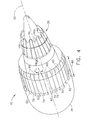
- Figure 2 is a side view of an exemplary nozzle design 11 that may be used with gas turbine engine 10.
- Engine 10 also includes a high pressure turbine 18, and a low pressure turbine 20.
- Fan assembly 12 includes an array of fan blades 24 extending radially outward from a rotor disc 26.
- Engine 10 has an intake side 28 and an exhaust side 30.
- the gas turbine engine is a GE90 available from General Electric Company, Cincinnati, Ohio.
- Fan assembly 12 and turbine 20 are coupled by a first rotor shaft 31, and compressor 14 and turbine 18 are coupled by a second rotor shaft 32.
- An exhaust assembly 33 extends downstream from core engine 13 and includes an annular fan exhaust nozzle 34 that extends around, and is spaced radially outwardly from, a core engine exhaust nozzle 35. More specifically, fan exhaust nozzle 34 is positioned upstream from core exhaust nozzle 35 and is spaced radially outwardly from core engine exhaust nozzle 35 such that an annular bypass stream outlet 36 is defined between fan exhaust nozzle 34 and an engine cowling 37 extending circumferentially around core engine 13.
- Core engine exhaust nozzle 35 also includes an annular outlet 38 defined between an inner surface 39 of cowling 37 and an outer surface 40 of a centerbody or center plug 41.
- core engine exhaust nozzle 35 is known as a long-ducted mixed flow exhaust and is discharged into stream outlet 36 upstream from centerbody 41, such that core combustion gases are mixed with bypass stream flow prior to the mixture being discharged from exhaust assembly 33.
- centerbody 41 extends aftward from core engine 13 such that core exhaust nozzle outlet 38 is upstream from an aft end 42 of centerbody 48.
- centerbody 41 does not extend downstream from nozzle outlet 38, and rather nozzle outlet 38 is downstream from centerbody 41.
- engine 10 is operated at a relatively high bypass ratio which is indicative of the amount of fan air which bypasses core engine 13 and is discharged through fan exhaust nozzle 34.
- gas turbine engine 10 is operable with a low bypass ratio.
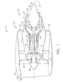
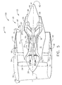
- Figure 3 is a side view of an exemplary noise suppression system 50 that can be used with gas turbine engine 10.
- Figure 4 is a perspective view of noise suppression system 50.
- noise suppression system 50 is operably coupled to core engine exhaust nozzle 35.
- Noise suppression system 50 includes a manifold 52 coupled to core engine exhaust nozzle 35 such that manifold 52 circumscribes core engine exhaust nozzle 35.
- Compressed air is discharged from an air source 54 through an actuation valve 56 into manifold 52.
- air is supplied to manifold 52 from at least one of fan assembly 12, high pressure compressor 14, high pressure turbine 18, or low pressure turbine 20.
- Noise suppression system 50 also includes a plurality of tubes 60 coupled to manifold 52 and operated such that air is discharged from manifold 52 through plurality of tubes 60 and into a core engine exhaust stream 85.
- noise suppression system 50 does not utilize tubes 60, but rather air is discharged into core engine exhaust stream 85 through other means.
- each tube 60 includes an upstream end 62, a downstream end 64, and a length 66 that is measured between upstream end 62 and downstream end 64, respectively.
- length 66 is sized such that upstream end 62 is coupled to manifold 52 and downstream end 64 is coupled to an end 68 of engine exhaust nozzle 35.
- tubes 60 are arranged in tube pairs 70 wherein each tube pair 70 includes a first tube 72 and a second tube 74. Moreover, in the exemplary embodiment, length 66 enables each tube 60 to extend approximately one-quarter of the way across each respective chevron 44 towards an aft end of each chevron 44.
- noise suppression system 50 includes eight pairs 70 of tubes 60 arranged azimuthally around an outer periphery of engine exhaust nozzle 35.
- noise suppression system 50 includes a plurality of tubes 60 that are not paired.
- noise suppression system 50 includes more or less than eight pairs 70 of tubes 60.
- each tube 60 is substantially hollow, has a substantially circular cross-sectional profile, and includes an opening 76 that extends along length 66 of tube 60.
- tube 60 does not have a circular cross-sectional profile.
- noise suppression system 50 includes four pairs 70 of tubes 60 arranged azimuthally around an outer periphery of core engine exhaust nozzle 35.
- Tubes 72 and 74 oriented approximately parallel to each other and a centerline axis 82. Furthermore, each tube pair 70 is oriented at an injection angle 80 that is measured with respect to a centerline axis 82.
- noise suppression system 50 is shown as coupled to an outer periphery of core engine exhaust nozzle 35, it should be realized that noise suppression system 50 could also be coupled to an inner periphery of core engine exhaust nozzle 35.
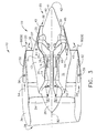
- Figure 5 is a side view of an exemplary noise suppression system 150 that can be used with gas turbine engine 10.
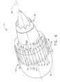
- Figure 6 is a perspective view of noise suppression system 150.
- Noise suppression system 150 is substantially similar to noise suppression system 50, (shown in Figures 3 and 4) and components of noise suppression system 150 that are identical to components of noise suppression system 50 are identified in Figures 5 and 6 using the same reference numerals used in Figures 3 and 4.
- noise suppression system 150 is operably coupled to fan nozzle 34.
- Noise suppression system 150 includes a manifold 52 coupled to engine exhaust nozzle 35 such that manifold 52 circumscribes engine exhaust nozzle 35.
- Compressed air is channeled from an air source 54 through an actuation valve 56 into manifold 52.
- air is supplied to manifold 52 from at least one of fan assembly 12, high pressure compressor 14, high pressure turbine 18, or low pressure turbine 20.
- air may be supplied from any other pressurized air source.
- synthetic jets are utilized within noise suppression system 50, and as such, no pressurized air is supplied to noise suppression system 50.
- Noise suppression system 150 also includes a plurality of tubes 60 coupled to manifold 52 and operated such that air is discharged from manifold 52 through plurality of tubes 60 and into a core engine exhaust stream 85.
- each tube 60 includes an upstream end 62, a downstream end 64, and a length 66 that is measured between upstream end 62 and downstream end 64, respectively.
- length 66 is sized such that upstream end 62 is coupled to manifold 52 and downstream end 64 is coupled to an end 68 of engine exhaust nozzle 35.
- Length 66 is variably selected to facilitate noise suppression system 150 achieving a desired noise suppression level.
- tubes 60 are arranged in tube pairs 70 wherein each tube pair 70 includes a first tube 72 and a second tube 74.
- noise suppression system 50 includes eight pairs 70 of tubes 60 arranged azimuthally around an outer periphery of engine exhaust nozzle 35.
- Each tube 60 is substantially hollow and includes an opening 76 that extends along length 66 of tube 60.
- opening 76 is approximately 0.125 inches in diameter.
- opening 76 is approximately 0.0625 inches in diameter.
- noise suppression system 50 includes four pairs 70 of tubes 60 arranged azimuthally around an outer periphery of core engine exhaust nozzle 35. Tubes 72 and 74 oriented approximately parallel to each other and a centerline axis 82.
- each tube pair 70 is oriented at an injection angle 80 that is measured with respect to a centerline axis 82.
- noise suppression system 150 is shown as coupled to an outer periphery of fan nozzle 34, it should be realized that noise suppression system 150 can also be coupled to an inner periphery of fan nozzle 34.
- tube pairs 70 i.e. "jets” are positioned at a desired injection angle 80 such that air discharged from each tube pair 70 is channeled across chevrons 44 and into each of the trailing vortices that are generated along and downstream each side 100 of each chevron 44.
- Injection angle 80 is variably selected to facilitate achieving a desired noise suppression level. Channeling air across chevrons 44 facilitates controlling vortex breakdown by energizing the vortex core.
- a small jet of compressed air is injected into the vortex core and interacts with the vortex to facilitate enhancing mixing between the core and fan flow, and between the fan and ambient flows, thus substantially delaying vortex breakdown and energizing vortex to facilitate maintaining the vortex core coherence over a longer distance downstream from the trailing edge, thus reducing the jet noise. Additionally, by preventing vortex breakdown, and by enhancing the mixing, the production of small scale turbulence is substantially prevented and sources of high frequency noise are substantially minimized.
- each noise suppression system 50 or 150 can be operated in either an activated mode or a de-activated mode.
- air is supplied into manifold 52 and distributed substantially uniformly among the plurality of pairs of tubes 70. Since each pair of tubes 70 includes a first tube 72 and a second tube 74 that are offset from nozzle 11 by a predefined angle 80, the air discharged from each pair of tubes 70 is channeled across plurality of chevrons 42 into each of the trailing vortices that are generated downstream from each chevron 44.
- noise suppression system is deactivated, no air is channeled through pairs of tubes 70.
- the "jets" are generated by any other means that substantially mimics the function of the tubes 60, such as, but not limited to, positioning a plurality of shaped holes, i.e., scoops, upstream from the plurality of chevrons 44 to channel a small quantity of core flow into the fan stream side, or from the fan flow into the free stream side by account of the pressure differences that exist between each one of the two streams.
- the above-described noise suppression system includes a manifold and plurality of pairs of hollow injection tubes, i.e. "jets", coupled to the manifold, wherein each pair of tubes discharges air across a plurality of chevrons 44 coupled to either the core engine nozzle or the fan nozzle. More specifically, the above-described noise suppression system includes a manifold and plurality of pairs of hollow tubes that are oriented at a complex angle, i.e. angle 80, wherein each tube has a predetermined opening such that the air discharged across the plurality of chevrons 44, has an injection velocity, a relative velocity and a mass-flow-rate that are variably selected to simulate a mechanical chevron.
- the injection tubes are positioned azimuthally around either the core engine nozzle or the fan nozzle to facilitate increasing the effectiveness of the chevron mixing effect within the engine shear layer and delaying formation of small scale turbulence.
- the "jets" flow can be controlled to maximize the effect during take-off and landing and be activated when desired to facilitate eliminating a performance penalty associated with chevrons during most of the flight duration, and/or to facilitate suppressing an infra-red signature generated by engine 10.
- Noise suppression system can be operated either continuously or by pulsating control valve 56. Operating the noise suppression system by pulsating valve 56 facilitates increasing effective amount of secondary airflow injected across the plurality of chevrons. Accordingly, the noise suppression system described herein facilitates reducing noise during takeoff or landing, and reducing or eliminating engine performance losses during cruise conditions.
- the noise suppression system facilitates enhancing mixing between the core engine flow and fan flow, and between the fan and ambient flows and thereby facilitates reducing jet noise without increasing high frequency noise.
- the noise suppression system described herein also facilitates reducing the thrust penalty caused by the chevrons by minimizing the losses incurred due to the vortex breakdown instability process.
- noise suppression systems 50 or 150 can be configured with a plurality of parallel tube pairs wherein the system includes a plurality of tubes having a first length and a plurality of tubes having a second length that is longer than the first length.
- noise suppression system 50 or 150 includes a plurality of additional tubes having at least a third length that is different than that of the first and/or second tube lengths.
- noise suppression systems are described above in detail.
- the noise suppression systems are not limited to the specific embodiments described herein, but rather, components of each assembly may be utilized independently and separately from other components described herein.
- each noise suppression component can also be used in combination with other exhaust assemblies and/or other noise suppression systems.
Landscapes
- Engineering & Computer Science (AREA)
- Chemical & Material Sciences (AREA)
- Combustion & Propulsion (AREA)
- Mechanical Engineering (AREA)
- General Engineering & Computer Science (AREA)
- Structures Of Non-Positive Displacement Pumps (AREA)
- Supercharger (AREA)
Abstract
Description
- This invention relates generally to gas turbine engines, and more particularly to methods and apparatus for operating gas turbine engines.
- At least some known gas turbine engines include a core engine having, in serial flow arrangement, a fan assembly and a high pressure compressor which compress airflow entering the engine, a combustor which burns a mixture of fuel and air, and low and high pressure rotary assemblies which each include a plurality of rotor blades that extract rotational energy from airflow exiting the combustor.
- Combustion gases are discharged from the core engine through an exhaust assembly. More specifically, within at least some known turbofan engines, a core exhaust nozzle discharges core exhaust gases radially inwardly from a concentric fan exhaust nozzle which exhausts fan discharge air therefrom for producing thrust. Generally during engine operation, both exhaust flows approach their maximum velocity during high power engine operations, such as during take-off operations. During such operations, as the high velocity flows interact with each other and with ambient air flowing past the engine, substantial noise may be produced along the take-off path of the aircraft.
- To facilitate reducing such noise, at least some known turbine engine exhaust assemblies utilize noise suppression equipment which includes at least one of tabs, mixing lobes, and/or a plurality of chevrons to enhance mixing the core and bypass exhaust flows. Although the tabs, mixing lobes, and chevrons facilitate suppressing noise during high power engine operating conditions, because the tabs, mixing lobes, and chevrons are mechanical devices which remain positioned in the flow path during all flight conditions, such devices may adversely impact engine performance during non-take-off operating conditions. Specifically, during cruise conditions, the tabs, the mixing lobes, and/or the chevrons may adversely impact specific fuel consumption (SFC) of the engine.
- In one aspect of the invention, a method for operating a gas turbine engine is provided. The method includes channeling compressed air from the gas turbine engine to a noise suppression system, and selectively operating the noise suppression system such that air discharged from the noise suppression system generates a streamwise vortex downstream from each respective chevron.
- In another aspect, an assembly for a gas turbine engine is provided. The assembly includes a gas turbine nozzle, a plurality of chevrons coupled to the gas turbine nozzle, and a noise suppression system coupled to the gas turbine nozzle, wherein the noise suppression system is selectively operable to facilitate generating a streamwise vortex downstream from each respective chevron.
- In a further aspect, a gas turbine engine is provided. The gas turbine engine includes a core engine nozzle, a fan nozzle, a plurality of chevrons coupled to at least one of the core engine nozzle and the fan nozzle, and a noise suppression system coupled to at least one of the core engine nozzle and the fan nozzle, wherein the noise suppression system is selectively operable to facilitate generating a streamwise vortex downstream from each respective chevron.
- The invention will now be described in greater detail, by way of example, with reference to the drawings, in which:-
- Figure 1 is a schematic illustration of an exemplary gas turbine engine;
- Figure 2 is a side view of an exemplary chevron nozzle design that may be used with the gas turbine engine shown in Figure 1;
- Figure 3 is a side view of an exemplary noise suppression system that may be used with the gas turbine engine shown in Figure 1;
- Figure 4 is a perspective view of the noise suppression system shown in Figure 3;
- Figure 5 is a side view of an alternative embodiment of a noise suppression system that may be used with the gas turbine engine shown in Figure 1; and
- Figure 6 is a perspective view of the noise suppression system shown in Figure 5.
-
- Figure 1 is a schematic illustration of a
gas turbine engine 10 including afan assembly 12 and acore engine 13 including ahigh pressure compressor 14, and acombustor 16. Figure 2 is a side view of anexemplary nozzle design 11 that may be used withgas turbine engine 10.Engine 10 also includes ahigh pressure turbine 18, and alow pressure turbine 20.Fan assembly 12 includes an array offan blades 24 extending radially outward from arotor disc 26.Engine 10 has anintake side 28 and anexhaust side 30. In one embodiment, the gas turbine engine is a GE90 available from General Electric Company, Cincinnati, Ohio.Fan assembly 12 andturbine 20 are coupled by afirst rotor shaft 31, andcompressor 14 andturbine 18 are coupled by asecond rotor shaft 32. - An
exhaust assembly 33 extends downstream fromcore engine 13 and includes an annularfan exhaust nozzle 34 that extends around, and is spaced radially outwardly from, a coreengine exhaust nozzle 35. More specifically,fan exhaust nozzle 34 is positioned upstream fromcore exhaust nozzle 35 and is spaced radially outwardly from coreengine exhaust nozzle 35 such that an annularbypass stream outlet 36 is defined betweenfan exhaust nozzle 34 and an engine cowling 37 extending circumferentially aroundcore engine 13. - Core
engine exhaust nozzle 35 also includes anannular outlet 38 defined between aninner surface 39 of cowling 37 and anouter surface 40 of a centerbody orcenter plug 41. In an alternative embodiment, coreengine exhaust nozzle 35 is known as a long-ducted mixed flow exhaust and is discharged intostream outlet 36 upstream fromcenterbody 41, such that core combustion gases are mixed with bypass stream flow prior to the mixture being discharged fromexhaust assembly 33. In the exemplary embodiment,centerbody 41 extends aftward fromcore engine 13 such that coreexhaust nozzle outlet 38 is upstream from anaft end 42 ofcenterbody 48. In an alternative embodiment,centerbody 41 does not extend downstream fromnozzle outlet 38, and rathernozzle outlet 38 is downstream fromcenterbody 41. - In the exemplary embodiment,
nozzle design 11 includes at least one offan nozzle exhaust 34 or coreengine exhaust nozzle 35.Nozzle design 11 includes a plurality of circumferentially adjoiningchevrons 44 that are positioned at anaft end 45 of eitherfan exhaust nozzle 34 and/or coreengine exhaust nozzle 35. Eachchevron 44 has a geometric shape that facilitates noise suppression, as described herein. In the exemplary embodiment, eachchevron 44 has a substantially triangular shape and includes abase 47 that is fixedly coupled or integrally joined to eitherfan nozzle exhaust 34 or coreengine exhaust nozzle 35. Eachchevron 44 also includes a radiallyouter surface 48, and a radially oppositeinner surface 49. - During operation, air flows through
fan assembly 12 and compressed air is supplied tohigh pressure compressor 14. The highly compressed air is delivered tocombustor 16. Airflow (not shown in Figure 1) fromcombustor 16drives turbines turbine 20drives fan assembly 12 by way ofshaft 31. More specifically, to produce thrust fromengine 10, fan discharge flow is discharged throughfan exhaust nozzle 34, and core combustion gases are discharged fromengine 10 through coreengine exhaust nozzle 35. In one embodiment,engine 10 is operated at a relatively high bypass ratio which is indicative of the amount of fan air which bypassescore engine 13 and is discharged throughfan exhaust nozzle 34. In an alternative embodiment,gas turbine engine 10 is operable with a low bypass ratio. - Figure 3 is a side view of an exemplary noise suppression system 50 that can be used with
gas turbine engine 10. Figure 4 is a perspective view of noise suppression system 50. In an exemplary embodiment, noise suppression system 50 is operably coupled to coreengine exhaust nozzle 35. Noise suppression system 50 includes amanifold 52 coupled to coreengine exhaust nozzle 35 such that manifold 52 circumscribes coreengine exhaust nozzle 35. Compressed air is discharged from anair source 54 through anactuation valve 56 intomanifold 52. In the exemplary embodiment, air is supplied to manifold 52 from at least one offan assembly 12,high pressure compressor 14,high pressure turbine 18, orlow pressure turbine 20. - Noise suppression system 50 also includes a plurality of
tubes 60 coupled tomanifold 52 and operated such that air is discharged frommanifold 52 through plurality oftubes 60 and into a coreengine exhaust stream 85. In other embodiments, noise suppression system 50 does not utilizetubes 60, but rather air is discharged into coreengine exhaust stream 85 through other means. Accordingly, eachtube 60 includes anupstream end 62, adownstream end 64, and alength 66 that is measured betweenupstream end 62 anddownstream end 64, respectively. In the exemplary embodiment,length 66 is sized such thatupstream end 62 is coupled tomanifold 52 anddownstream end 64 is coupled to anend 68 ofengine exhaust nozzle 35. In the exemplary embodiment,tubes 60 are arranged intube pairs 70 wherein eachtube pair 70 includes afirst tube 72 and asecond tube 74. Moreover, in the exemplary embodiment,length 66 enables eachtube 60 to extend approximately one-quarter of the way across eachrespective chevron 44 towards an aft end of eachchevron 44. - In the exemplary embodiment, noise suppression system 50 includes eight
pairs 70 oftubes 60 arranged azimuthally around an outer periphery ofengine exhaust nozzle 35. In an alternative embodiment, noise suppression system 50 includes a plurality oftubes 60 that are not paired. In another alternative embodiment, noise suppression system 50 includes more or less than eightpairs 70 oftubes 60. In the exemplary embodiment, eachtube 60 is substantially hollow, has a substantially circular cross-sectional profile, and includes an opening 76 that extends alonglength 66 oftube 60. Alternatively,tube 60 does not have a circular cross-sectional profile. In the exemplary embodiment, noise suppression system 50 includes fourpairs 70 oftubes 60 arranged azimuthally around an outer periphery of coreengine exhaust nozzle 35.Tubes centerline axis 82. Furthermore, eachtube pair 70 is oriented at aninjection angle 80 that is measured with respect to acenterline axis 82. Although noise suppression system 50 is shown as coupled to an outer periphery of coreengine exhaust nozzle 35, it should be realized that noise suppression system 50 could also be coupled to an inner periphery of coreengine exhaust nozzle 35. - Figure 5 is a side view of an exemplary
noise suppression system 150 that can be used withgas turbine engine 10. Figure 6 is a perspective view ofnoise suppression system 150.Noise suppression system 150 is substantially similar to noise suppression system 50, (shown in Figures 3 and 4) and components ofnoise suppression system 150 that are identical to components of noise suppression system 50 are identified in Figures 5 and 6 using the same reference numerals used in Figures 3 and 4. - In an exemplary embodiment,
noise suppression system 150 is operably coupled tofan nozzle 34.Noise suppression system 150 includes a manifold 52 coupled toengine exhaust nozzle 35 such thatmanifold 52 circumscribesengine exhaust nozzle 35. Compressed air is channeled from anair source 54 through anactuation valve 56 intomanifold 52. In the exemplary embodiment, air is supplied to manifold 52 from at least one offan assembly 12,high pressure compressor 14,high pressure turbine 18, orlow pressure turbine 20. Alternatively, air may be supplied from any other pressurized air source. In another alternative embodiment, synthetic jets are utilized within noise suppression system 50, and as such, no pressurized air is supplied to noise suppression system 50. -
Noise suppression system 150 also includes a plurality oftubes 60 coupled tomanifold 52 and operated such that air is discharged frommanifold 52 through plurality oftubes 60 and into a coreengine exhaust stream 85. Accordingly, eachtube 60 includes anupstream end 62, adownstream end 64, and alength 66 that is measured betweenupstream end 62 anddownstream end 64, respectively. In the exemplary embodiment,length 66 is sized such thatupstream end 62 is coupled tomanifold 52 anddownstream end 64 is coupled to anend 68 ofengine exhaust nozzle 35.Length 66 is variably selected to facilitatenoise suppression system 150 achieving a desired noise suppression level. In the exemplary embodiment,tubes 60 are arranged in tube pairs 70 wherein eachtube pair 70 includes afirst tube 72 and asecond tube 74. - In the exemplary embodiment, noise suppression system 50 includes eight
pairs 70 oftubes 60 arranged azimuthally around an outer periphery ofengine exhaust nozzle 35. Eachtube 60 is substantially hollow and includes anopening 76 that extends alonglength 66 oftube 60. In oneembodiment opening 76 is approximately 0.125 inches in diameter. In another embodiment, opening 76 is approximately 0.0625 inches in diameter. In the exemplary embodiment, noise suppression system 50 includes fourpairs 70 oftubes 60 arranged azimuthally around an outer periphery of coreengine exhaust nozzle 35.Tubes centerline axis 82. Furthermore, eachtube pair 70 is oriented at aninjection angle 80 that is measured with respect to acenterline axis 82. Althoughnoise suppression system 150 is shown as coupled to an outer periphery offan nozzle 34, it should be realized thatnoise suppression system 150 can also be coupled to an inner periphery offan nozzle 34. - During operation, tube pairs 70, i.e. "jets" are positioned at a desired
injection angle 80 such that air discharged from eachtube pair 70 is channeled acrosschevrons 44 and into each of the trailing vortices that are generated along and downstream eachside 100 of eachchevron 44.Injection angle 80 is variably selected to facilitate achieving a desired noise suppression level. Channeling air acrosschevrons 44 facilitates controlling vortex breakdown by energizing the vortex core. More specifically, a small jet of compressed air is injected into the vortex core and interacts with the vortex to facilitate enhancing mixing between the core and fan flow, and between the fan and ambient flows, thus substantially delaying vortex breakdown and energizing vortex to facilitate maintaining the vortex core coherence over a longer distance downstream from the trailing edge, thus reducing the jet noise. Additionally, by preventing vortex breakdown, and by enhancing the mixing, the production of small scale turbulence is substantially prevented and sources of high frequency noise are substantially minimized. - More specifically, each
noise suppression system 50 or 150 can be operated in either an activated mode or a de-activated mode. Whennoise suppression system 50 or 150 are operated in the activated mode, air is supplied intomanifold 52 and distributed substantially uniformly among the plurality of pairs oftubes 70. Since each pair oftubes 70 includes afirst tube 72 and asecond tube 74 that are offset fromnozzle 11 by apredefined angle 80, the air discharged from each pair oftubes 70 is channeled across plurality ofchevrons 42 into each of the trailing vortices that are generated downstream from eachchevron 44. When noise suppression system is deactivated, no air is channeled through pairs oftubes 70. - In an alternative embodiment, the "jets" are generated by any other means that substantially mimics the function of the
tubes 60, such as, but not limited to, positioning a plurality of shaped holes, i.e., scoops, upstream from the plurality ofchevrons 44 to channel a small quantity of core flow into the fan stream side, or from the fan flow into the free stream side by account of the pressure differences that exist between each one of the two streams. - The above-described noise suppression system includes a manifold and plurality of pairs of hollow injection tubes, i.e. "jets", coupled to the manifold, wherein each pair of tubes discharges air across a plurality of
chevrons 44 coupled to either the core engine nozzle or the fan nozzle. More specifically, the above-described noise suppression system includes a manifold and plurality of pairs of hollow tubes that are oriented at a complex angle, i.e.angle 80, wherein each tube has a predetermined opening such that the air discharged across the plurality ofchevrons 44, has an injection velocity, a relative velocity and a mass-flow-rate that are variably selected to simulate a mechanical chevron. The injection tubes are positioned azimuthally around either the core engine nozzle or the fan nozzle to facilitate increasing the effectiveness of the chevron mixing effect within the engine shear layer and delaying formation of small scale turbulence. - The "jets" flow can be controlled to maximize the effect during take-off and landing and be activated when desired to facilitate eliminating a performance penalty associated with chevrons during most of the flight duration, and/or to facilitate suppressing an infra-red signature generated by
engine 10. Noise suppression system can be operated either continuously or by pulsatingcontrol valve 56. Operating the noise suppression system by pulsatingvalve 56 facilitates increasing effective amount of secondary airflow injected across the plurality of chevrons. Accordingly, the noise suppression system described herein facilitates reducing noise during takeoff or landing, and reducing or eliminating engine performance losses during cruise conditions. - Accordingly, the noise suppression system facilitates enhancing mixing between the core engine flow and fan flow, and between the fan and ambient flows and thereby facilitates reducing jet noise without increasing high frequency noise. The noise suppression system described herein also facilitates reducing the thrust penalty caused by the chevrons by minimizing the losses incurred due to the vortex breakdown instability process.
- In an alternative embodiment,
noise suppression systems 50 or 150 can be configured with a plurality of parallel tube pairs wherein the system includes a plurality of tubes having a first length and a plurality of tubes having a second length that is longer than the first length. In another exemplary embodiment,noise suppression system 50 or 150 includes a plurality of additional tubes having at least a third length that is different than that of the first and/or second tube lengths. - Exemplary embodiments of noise suppression systems and exhaust assemblies are described above in detail. The noise suppression systems are not limited to the specific embodiments described herein, but rather, components of each assembly may be utilized independently and separately from other components described herein. For example, each noise suppression component can also be used in combination with other exhaust assemblies and/or other noise suppression systems.
Claims (10)
- An assembly (11) for a gas turbine engine (10), said assembly comprising:a gas turbine nozzle (34, 35);a plurality of chevrons (44) coupled to said gas turbine nozzle; anda noise suppression system (50) coupled to said gas turbine nozzle, said noise suppression system is selectively operable to facilitate enhancing a streamwise vortex generated downstream from each respective chevron.
- An assembly (11) in accordance with Claim 1 wherein said noise suppression system (50) further comprises:a manifold (52) coupled to said gas turbine nozzle (34, 35); anda plurality of tubes (60) coupled to said manifold, each of said plurality of tubes is selectively oriented to facilitate enhancing a vortex generated in said gas turbine nozzle chevron flowpath.
- An assembly (11) in accordance with Claim 2 wherein said plurality of tubes (60) comprises a plurality of tube pairs (70) comprising:a first tube (72) that extends radially inward at an angle β with respect to a centerline axis; anda second tube (74) that extends radially inward at the angle β with respect to the centerline axis, said first tube oriented approximately parallel to said second tube.
- An assembly (11) in accordance with Claim 2 wherein each of said plurality of tube pairs (70) is selectively oriented to facilitate generating a streamwise vortex downstream from each respective chevron (44) in a core gas turbine engine nozzle flowpath.
- An assembly (11) in accordance with Claim 2 wherein each of said plurality of tube pairs (70) is selectively oriented to facilitate generating a streamwise vortex downstream from each respective chevron (44) in a fan nozzle flowpath.
- An assembly (11) in accordance with Claim 1 wherein said noise suppression system (50) further comprises:a manifold (52) coupled to said gas turbine nozzle (34, 35); andexactly eight tube pairs (70) coupled to said manifold, each said tube pair being selectively oriented to facilitate generating a streamwise vortex downstream from each respective chevron (44).
- An assembly (11) in accordance with Claim 1 wherein said noise suppression system (50) further comprises an actuation valve selectively (56) operable to discharge compressed air from said gas turbine engine (10) to said noise suppression system, such that said noise suppression system is at least one of continuously operated or pulse operated.
- A gas turbine engine (10) comprising:a core engine nozzle (35);a fan nozzle (34);a plurality of chevrons (44) coupled to at least one of said core engine nozzle and said fan nozzle; anda noise suppression system (50) coupled to at least one of said core engine nozzle and said fan nozzle, said noise suppression system is selectively operable to facilitate enhancing a streamwise vortex generated downstream from each respective chevron.
- A gas turbine (10) in accordance with Claim 8 wherein said noise suppression system (50) further comprises:a manifold (52) coupled to said gas turbine nozzle (34, 35); anda plurality of tube pairs (70) coupled to said manifold, each said tube pair is selectively oriented to facilitate enhancing a vortex generated downstream from each respective chevron.
- A gas turbine (10) in accordance with Claim 9 wherein each said tube pair (70) comprises:a first tube (72) that extends radially inward at an angle β with respect to a centerline axis; anda second tube (74) that extends radially inward at the angle β with respect to the centerline axis, said first tube oriented approximately parallel to said second tube.
Applications Claiming Priority (2)
| Application Number | Priority Date | Filing Date | Title |
|---|---|---|---|
| US810142 | 2004-03-26 | ||
| US10/810,142 US7246481B2 (en) | 2004-03-26 | 2004-03-26 | Methods and apparatus for operating gas turbine engines |
Publications (3)
| Publication Number | Publication Date |
|---|---|
| EP1580418A2 true EP1580418A2 (en) | 2005-09-28 |
| EP1580418A3 EP1580418A3 (en) | 2007-04-18 |
| EP1580418B1 EP1580418B1 (en) | 2009-01-07 |
Family
ID=34862102
Family Applications (1)
| Application Number | Title | Priority Date | Filing Date |
|---|---|---|---|
| EP05251816A Expired - Lifetime EP1580418B1 (en) | 2004-03-26 | 2005-03-23 | Gas turbine engine comprising a noise suppression system |
Country Status (3)
| Country | Link |
|---|---|
| US (1) | US7246481B2 (en) |
| EP (1) | EP1580418B1 (en) |
| DE (1) | DE602005012168D1 (en) |
Cited By (15)
| Publication number | Priority date | Publication date | Assignee | Title |
|---|---|---|---|---|
| WO2007122368A1 (en) * | 2006-04-25 | 2007-11-01 | Short Brothers Plc | Variable area exhaust nozzle |
| FR2901321A1 (en) * | 2006-05-18 | 2007-11-23 | Aircelle Sa | METHOD FOR HOMOGENIZING AIR FROM TURBOJET OUTPUT TO LOWER GENERATED NOISE |
| EP1905998A2 (en) | 2006-09-12 | 2008-04-02 | United Technologies Corporation | Asymmetric Serrated Nozzle For Exhaust Noise Reduction |
| WO2008045090A1 (en) * | 2006-10-12 | 2008-04-17 | United Technologies Corporation | Gas turbine engine with rotationally overlapped fan variable area nozzle |
| WO2008100712A2 (en) | 2007-02-14 | 2008-08-21 | The Boeing Company | Systems and methods for reducing noise from jet engine exhaust |
| EP2028360A1 (en) | 2007-08-23 | 2009-02-25 | Snecma | Dual-flow turbomachine with jet noise reduction |
| FR2929336A1 (en) * | 2008-03-31 | 2009-10-02 | Airbus France Sas | Jet engine for airplane, has ducts ejecting fluid jets in form of spray via outlet orifices such that ejected fluid jets form fluidic disturbances around ejected gas flow, where ducts are distributed at periphery of downstream end of wall |
| FR2929337A1 (en) * | 2008-03-31 | 2009-10-02 | Airbus France Sas | SECONDARY JET DEVICE FOR REDUCING NOISE GENERATED BY AN AIRCRAFT REACTOR |
| US7870722B2 (en) | 2006-12-06 | 2011-01-18 | The Boeing Company | Systems and methods for passively directing aircraft engine nozzle flows |
| US7966824B2 (en) | 2006-08-09 | 2011-06-28 | The Boeing Company | Jet engine nozzle exit configurations and associated systems and methods |
| WO2011141678A1 (en) | 2010-05-12 | 2011-11-17 | Snecma | Device for reducing the noise emitted by the jet of an aircraft propulsion engine |
| US8157207B2 (en) | 2006-08-09 | 2012-04-17 | The Boeing Company | Jet engine nozzle exit configurations, including projections oriented relative to pylons, and associated systems and methods |
| WO2013121150A1 (en) * | 2012-02-17 | 2013-08-22 | Herakles | Gas turbine aero engine afterbody assembly |
| WO2014105394A1 (en) * | 2012-12-28 | 2014-07-03 | United Technologies Corporation | Geared gas turbine engine exhaust nozzle with chevrons |
| FR3009027A1 (en) * | 2013-07-26 | 2015-01-30 | Airbus Operations Sas | AIRCRAFT TURBOMACHINE ASSEMBLY WITH ATTENUATED JET NOISE. |
Families Citing this family (24)
| Publication number | Priority date | Publication date | Assignee | Title |
|---|---|---|---|---|
| FR2866070B1 (en) * | 2004-02-05 | 2008-12-05 | Snecma Moteurs | TURBOREACTOR WITH HIGH DILUTION RATE |
| US7305817B2 (en) * | 2004-02-09 | 2007-12-11 | General Electric Company | Sinuous chevron exhaust nozzle |
| FR2868131B1 (en) * | 2004-03-25 | 2006-06-09 | Airbus France Sas | PRIME TUBE WITH CHEVRONS FOR A DOUBLE FLOW AIRCRAFT AIRCRAFT AND AIRCRAFT COMPRISING SUCH TUYERE |
| US7412832B2 (en) * | 2004-03-26 | 2008-08-19 | General Electric Company | Method and apparatus for operating gas turbine engines |
| GB0505246D0 (en) * | 2005-03-15 | 2005-04-20 | Rolls Royce Plc | Engine noise |
| US7543452B2 (en) * | 2005-08-10 | 2009-06-09 | United Technologies Corporation | Serrated nozzle trailing edge for exhaust noise suppression |
| FR2892152B1 (en) * | 2005-10-19 | 2007-11-23 | Airbus France Sas | TURBOMOTEUR WITH ATTENUATED JET NOISE |
| FR2904663B1 (en) * | 2006-08-01 | 2012-02-03 | Snecma | DOUBLE FLOW TURBOMACHINE WITH ARTIFICIAL VARIATION OF ITS COLLEGE SECTION |
| US8001762B2 (en) * | 2006-08-04 | 2011-08-23 | Efremkin Artem P | Method and device to increase thrust and efficiency of jet engine |
| US8015819B2 (en) * | 2006-09-29 | 2011-09-13 | The United States Of America As Represented By The Administrator Of The National Aeronautics And Space Administration | Wet active chevron nozzle for controllable jet noise reduction |
| US7963099B2 (en) * | 2007-05-21 | 2011-06-21 | General Electric Company | Fluted chevron exhaust nozzle |
| US7926285B2 (en) * | 2007-07-18 | 2011-04-19 | General Electric Company | Modular chevron exhaust nozzle |
| US8371806B2 (en) * | 2007-10-03 | 2013-02-12 | United Technologies Corporation | Gas turbine engine having core auxiliary duct passage |
| EP2256327B1 (en) * | 2008-02-25 | 2019-09-04 | IHI Corporation | Noise reducing device, and jet propulsion system |
| FR2929334B1 (en) * | 2008-03-31 | 2012-06-01 | Airbus France | DEVICE FOR REDUCING NOISE GENERATION BY AIRCRAFT REACTOR WITH BLEED FLUID CONDUITS |
| US8371124B2 (en) * | 2008-04-15 | 2013-02-12 | Aerion Corporation | Jet nozzle plug with varying, non-circular cross sections |
| FR2930972B1 (en) * | 2008-05-07 | 2012-11-30 | Airbus France | DOUBLE FLOW TURBOMACHINE FOR AIRCRAFT WITH REDUCED NOISE TRANSMISSION |
| JP5246425B2 (en) * | 2009-05-19 | 2013-07-24 | 株式会社Ihi | Aircraft jet engine noise reduction apparatus and method |
| US9528468B2 (en) * | 2009-10-28 | 2016-12-27 | Ihi Corporation | Noise reduction system |
| WO2011052566A1 (en) | 2009-10-28 | 2011-05-05 | 株式会社Ihi | Noise reduction device |
| FR2970744A1 (en) * | 2011-01-24 | 2012-07-27 | Airbus Operations Sas | AIRCRAFT REACTOR COMPRISING A NOISE REDUCTION SYSTEM GENERATED BY GAS EJECTION |
| CN103133180B (en) * | 2011-11-25 | 2015-06-10 | 中航商用航空发动机有限责任公司 | Low jet flow noise spray pipe and turbofan engine including the same |
| US9297334B2 (en) | 2012-05-25 | 2016-03-29 | King Abdulaziz City For Science And Technology | Exhaust nozzle of a gas turbine engine |
| GB201301702D0 (en) * | 2013-01-31 | 2013-03-20 | Rolls Royce Plc | Exhaust cone |
Citations (1)
| Publication number | Priority date | Publication date | Assignee | Title |
|---|---|---|---|---|
| EP0913567A2 (en) | 1997-10-31 | 1999-05-06 | General Electric Company | Chevron exhaust nozzle |
Family Cites Families (21)
| Publication number | Priority date | Publication date | Assignee | Title |
|---|---|---|---|---|
| US2990905A (en) * | 1957-05-13 | 1961-07-04 | Lilley Geoffrey Michael | Jet noise suppression means |
| US3392529A (en) * | 1965-07-23 | 1968-07-16 | Rolls Royce | Aircraft provided with a gas turbine vertical lift engine |
| US3495682A (en) * | 1968-02-28 | 1970-02-17 | Otis D Treiber | Jet engine exhaust silencer construction |
| US3527317A (en) * | 1969-04-18 | 1970-09-08 | Gen Electric | Sound control of turbofan engines |
| US3630311A (en) * | 1969-07-31 | 1971-12-28 | Gen Electric | Jet engine nozzle system for noise suppression |
| FR2094212A5 (en) * | 1970-05-11 | 1972-02-04 | Bertin & Cie | |
| US3964569A (en) * | 1974-09-06 | 1976-06-22 | General Electric Company | Gas turbine engine noise shield |
| US4064961A (en) * | 1976-04-05 | 1977-12-27 | Rohr Industries, Incorporated | Slanted cavity resonator |
| US4135363A (en) * | 1976-05-13 | 1979-01-23 | United Technologies Corporation | Device to provide flow inversion in a turbofan exhaust tailpipe to achieve low jet noise |
| US4244440A (en) * | 1978-12-01 | 1981-01-13 | General Electric Company | Apparatus for suppressing internally generated gas turbine engine low frequency noise |
| US4280587A (en) * | 1979-05-08 | 1981-07-28 | The Boeing Company | Noise-suppressing jet engine nozzles and method |
| US4446696A (en) * | 1981-06-29 | 1984-05-08 | General Electric Company | Compound propulsor |
| US5092425A (en) * | 1990-04-02 | 1992-03-03 | The United States Of America As Represented By The Secretary Of The Air Force | Jet noise suppressor and method |
| US5291672A (en) * | 1992-12-09 | 1994-03-08 | General Electric Company | Sound suppression mixer |
| US6612106B2 (en) * | 2000-05-05 | 2003-09-02 | The Boeing Company | Segmented mixing device having chevrons for exhaust noise reduction in jet engines |
| US6502383B1 (en) * | 2000-08-31 | 2003-01-07 | General Electric Company | Stub airfoil exhaust nozzle |
| EP2090769A1 (en) * | 2000-10-02 | 2009-08-19 | Rohr, Inc. | Apparatus, method and system for gas turbine engine noise reduction |
| US6532729B2 (en) * | 2001-05-31 | 2003-03-18 | General Electric Company | Shelf truncated chevron exhaust nozzle for reduction of exhaust noise and infrared (IR) signature |
| BR0307845B1 (en) * | 2002-02-22 | 2012-09-18 | duplex mixer exhaust nozzle. | |
| US6658839B2 (en) * | 2002-02-28 | 2003-12-09 | The Boeing Company | Convergent/divergent segmented exhaust nozzle |
| US6718752B2 (en) * | 2002-05-29 | 2004-04-13 | The Boeing Company | Deployable segmented exhaust nozzle for a jet engine |
-
2004
- 2004-03-26 US US10/810,142 patent/US7246481B2/en not_active Expired - Fee Related
-
2005
- 2005-03-23 EP EP05251816A patent/EP1580418B1/en not_active Expired - Lifetime
- 2005-03-23 DE DE602005012168T patent/DE602005012168D1/en not_active Expired - Lifetime
Patent Citations (1)
| Publication number | Priority date | Publication date | Assignee | Title |
|---|---|---|---|---|
| EP0913567A2 (en) | 1997-10-31 | 1999-05-06 | General Electric Company | Chevron exhaust nozzle |
Cited By (29)
| Publication number | Priority date | Publication date | Assignee | Title |
|---|---|---|---|---|
| WO2007122368A1 (en) * | 2006-04-25 | 2007-11-01 | Short Brothers Plc | Variable area exhaust nozzle |
| FR2901321A1 (en) * | 2006-05-18 | 2007-11-23 | Aircelle Sa | METHOD FOR HOMOGENIZING AIR FROM TURBOJET OUTPUT TO LOWER GENERATED NOISE |
| WO2007135257A1 (en) * | 2006-05-18 | 2007-11-29 | Aircelle | Turbojet nacelle equipped with means for reducing the noise produced by said turbojet |
| US8511090B2 (en) | 2006-08-09 | 2013-08-20 | The Boeing Company | Jet engine nozzle exit configurations and associated systems and methods |
| US8157207B2 (en) | 2006-08-09 | 2012-04-17 | The Boeing Company | Jet engine nozzle exit configurations, including projections oriented relative to pylons, and associated systems and methods |
| US7966824B2 (en) | 2006-08-09 | 2011-06-28 | The Boeing Company | Jet engine nozzle exit configurations and associated systems and methods |
| EP1905998A2 (en) | 2006-09-12 | 2008-04-02 | United Technologies Corporation | Asymmetric Serrated Nozzle For Exhaust Noise Reduction |
| EP1905998A3 (en) * | 2006-09-12 | 2011-05-18 | United Technologies Corporation | Asymmetric Serrated Nozzle For Exhaust Noise Reduction |
| WO2008045090A1 (en) * | 2006-10-12 | 2008-04-17 | United Technologies Corporation | Gas turbine engine with rotationally overlapped fan variable area nozzle |
| US7870722B2 (en) | 2006-12-06 | 2011-01-18 | The Boeing Company | Systems and methods for passively directing aircraft engine nozzle flows |
| US8166768B2 (en) | 2006-12-06 | 2012-05-01 | The Boeing Company | Systems and methods for passively directing aircraft engine nozzle flows |
| JP2012177369A (en) * | 2007-02-14 | 2012-09-13 | Boeing Co:The | System and method for reducing noise from jet engine exhaust |
| WO2008100712A2 (en) | 2007-02-14 | 2008-08-21 | The Boeing Company | Systems and methods for reducing noise from jet engine exhaust |
| JP2010518323A (en) * | 2007-02-14 | 2010-05-27 | ザ・ボーイング・カンパニー | System and method for reducing exhaust noise of a jet engine |
| WO2008100712A3 (en) * | 2007-02-14 | 2008-11-27 | Boeing Co | Systems and methods for reducing noise from jet engine exhaust |
| US7966826B2 (en) | 2007-02-14 | 2011-06-28 | The Boeing Company | Systems and methods for reducing noise from jet engine exhaust |
| CN101589217B (en) * | 2007-02-14 | 2012-07-04 | 波音公司 | Systems and methods for reducing jet engine exhaust noise |
| EP2028360A1 (en) | 2007-08-23 | 2009-02-25 | Snecma | Dual-flow turbomachine with jet noise reduction |
| CN101372926B (en) * | 2007-08-23 | 2013-05-29 | 斯奈克玛 | Dual-flow turbomachine with jet noise reduction |
| US8132756B2 (en) | 2008-03-31 | 2012-03-13 | Centre National De La Recherche Scientifique (Cnrs) | Device with plane jets for reducing the noise generated by an aircraft engine |
| FR2929336A1 (en) * | 2008-03-31 | 2009-10-02 | Airbus France Sas | Jet engine for airplane, has ducts ejecting fluid jets in form of spray via outlet orifices such that ejected fluid jets form fluidic disturbances around ejected gas flow, where ducts are distributed at periphery of downstream end of wall |
| FR2929337A1 (en) * | 2008-03-31 | 2009-10-02 | Airbus France Sas | SECONDARY JET DEVICE FOR REDUCING NOISE GENERATED BY AN AIRCRAFT REACTOR |
| US8393139B2 (en) | 2008-03-31 | 2013-03-12 | Airbus Operations (S.A.S.) | Device with secondary jets reducing the noise generated by an aircraft jet engine |
| WO2009133273A3 (en) * | 2008-03-31 | 2009-12-23 | Airbus Operations | Device with secondary jets reducing the noise generated by an aircraft jet engine |
| WO2011141678A1 (en) | 2010-05-12 | 2011-11-17 | Snecma | Device for reducing the noise emitted by the jet of an aircraft propulsion engine |
| WO2013121150A1 (en) * | 2012-02-17 | 2013-08-22 | Herakles | Gas turbine aero engine afterbody assembly |
| FR2987078A1 (en) * | 2012-02-17 | 2013-08-23 | Snecma Propulsion Solide | REAR BODY ASSEMBLY OF AERONAUTICAL GAS TURBINE ENGINE |
| WO2014105394A1 (en) * | 2012-12-28 | 2014-07-03 | United Technologies Corporation | Geared gas turbine engine exhaust nozzle with chevrons |
| FR3009027A1 (en) * | 2013-07-26 | 2015-01-30 | Airbus Operations Sas | AIRCRAFT TURBOMACHINE ASSEMBLY WITH ATTENUATED JET NOISE. |
Also Published As
| Publication number | Publication date |
|---|---|
| EP1580418A3 (en) | 2007-04-18 |
| DE602005012168D1 (en) | 2009-02-26 |
| EP1580418B1 (en) | 2009-01-07 |
| US20050214107A1 (en) | 2005-09-29 |
| US7246481B2 (en) | 2007-07-24 |
Similar Documents
| Publication | Publication Date | Title |
|---|---|---|
| EP1580418B1 (en) | Gas turbine engine comprising a noise suppression system | |
| US20240344487A1 (en) | Propulsion system architecture | |
| EP1655474B1 (en) | Thrust vectoring aft flade engine | |
| EP1533510B1 (en) | Two-spool variable cycle gas turbine engine | |
| US7412832B2 (en) | Method and apparatus for operating gas turbine engines | |
| EP1561939B1 (en) | Sinuous chevron exhaust nozzle | |
| US7055329B2 (en) | Method and apparatus for noise attenuation for gas turbine engines using at least one synthetic jet actuator for injecting air | |
| US6532729B2 (en) | Shelf truncated chevron exhaust nozzle for reduction of exhaust noise and infrared (IR) signature | |
| JP4619089B2 (en) | FLADE gas turbine engine with fixed geometry inlet | |
| EP3473818B1 (en) | Trapped vortex combustor for a gas turbine engine | |
| CA2609282C (en) | Turbofan engine cowl assembly and method of operating the same | |
| EP3036422B1 (en) | High performance convergent divergent nozzle | |
| CA2520471C (en) | Methods and apparatus for assembling a gas turbine engine | |
| CN107013268A (en) | Compression radome fairing for jet engine exhaust | |
| US9422887B2 (en) | Device for reducing the noise emitted by the jet of an aircraft propulsion engine | |
| US11920539B1 (en) | Gas turbine exhaust nozzle noise abatement | |
| EP4703643A1 (en) | Spill return fuel nozzles for usage as start nozzles | |
| GB2640728A (en) | Combustors and methods of mitigating thermoacoustic instabilities in a gas flow |
Legal Events
| Date | Code | Title | Description |
|---|---|---|---|
| PUAI | Public reference made under article 153(3) epc to a published international application that has entered the european phase |
Free format text: ORIGINAL CODE: 0009012 |
|
| AK | Designated contracting states |
Kind code of ref document: A2 Designated state(s): AT BE BG CH CY CZ DE DK EE ES FI FR GB GR HU IE IS IT LI LT LU MC NL PL PT RO SE SI SK TR |
|
| AX | Request for extension of the european patent |
Extension state: AL BA HR LV MK YU |
|
| PUAL | Search report despatched |
Free format text: ORIGINAL CODE: 0009013 |
|
| AK | Designated contracting states |
Kind code of ref document: A3 Designated state(s): AT BE BG CH CY CZ DE DK EE ES FI FR GB GR HU IE IS IT LI LT LU MC NL PL PT RO SE SI SK TR |
|
| AX | Request for extension of the european patent |
Extension state: AL BA HR LV MK YU |
|
| 17P | Request for examination filed |
Effective date: 20071018 |
|
| 17Q | First examination report despatched |
Effective date: 20071115 |
|
| AKX | Designation fees paid |
Designated state(s): DE FR GB |
|
| GRAP | Despatch of communication of intention to grant a patent |
Free format text: ORIGINAL CODE: EPIDOSNIGR1 |
|
| GRAS | Grant fee paid |
Free format text: ORIGINAL CODE: EPIDOSNIGR3 |
|
| GRAA | (expected) grant |
Free format text: ORIGINAL CODE: 0009210 |
|
| AK | Designated contracting states |
Kind code of ref document: B1 Designated state(s): DE FR GB |
|
| REG | Reference to a national code |
Ref country code: GB Ref legal event code: FG4D |
|
| REF | Corresponds to: |
Ref document number: 602005012168 Country of ref document: DE Date of ref document: 20090226 Kind code of ref document: P |
|
| PLBE | No opposition filed within time limit |
Free format text: ORIGINAL CODE: 0009261 |
|
| STAA | Information on the status of an ep patent application or granted ep patent |
Free format text: STATUS: NO OPPOSITION FILED WITHIN TIME LIMIT |
|
| 26N | No opposition filed |
Effective date: 20091008 |
|
| REG | Reference to a national code |
Ref country code: FR Ref legal event code: PLFP Year of fee payment: 12 |
|
| PGFP | Annual fee paid to national office [announced via postgrant information from national office to epo] |
Ref country code: GB Payment date: 20160329 Year of fee payment: 12 Ref country code: FR Payment date: 20160328 Year of fee payment: 12 |
|
| PGFP | Annual fee paid to national office [announced via postgrant information from national office to epo] |
Ref country code: DE Payment date: 20160331 Year of fee payment: 12 |
|
| REG | Reference to a national code |
Ref country code: DE Ref legal event code: R119 Ref document number: 602005012168 Country of ref document: DE |
|
| GBPC | Gb: european patent ceased through non-payment of renewal fee |
Effective date: 20170323 |
|
| REG | Reference to a national code |
Ref country code: FR Ref legal event code: ST Effective date: 20171130 |
|
| PG25 | Lapsed in a contracting state [announced via postgrant information from national office to epo] |
Ref country code: DE Free format text: LAPSE BECAUSE OF NON-PAYMENT OF DUE FEES Effective date: 20171003 Ref country code: FR Free format text: LAPSE BECAUSE OF NON-PAYMENT OF DUE FEES Effective date: 20170331 |
|
| PG25 | Lapsed in a contracting state [announced via postgrant information from national office to epo] |
Ref country code: GB Free format text: LAPSE BECAUSE OF NON-PAYMENT OF DUE FEES Effective date: 20170323 |