EP2117971B1 - Fördersystem - Google Patents
Fördersystem Download PDFInfo
- Publication number
- EP2117971B1 EP2117971B1 EP08700531A EP08700531A EP2117971B1 EP 2117971 B1 EP2117971 B1 EP 2117971B1 EP 08700531 A EP08700531 A EP 08700531A EP 08700531 A EP08700531 A EP 08700531A EP 2117971 B1 EP2117971 B1 EP 2117971B1
- Authority
- EP
- European Patent Office
- Prior art keywords
- conveyor unit
- conveyor
- rollers
- drive
- joint
- Prior art date
- Legal status (The legal status is an assumption and is not a legal conclusion. Google has not performed a legal analysis and makes no representation as to the accuracy of the status listed.)
- Not-in-force
Links
- 230000005540 biological transmission Effects 0.000 claims description 11
- 125000006850 spacer group Chemical group 0.000 description 10
- 230000007704 transition Effects 0.000 description 6
- 238000005452 bending Methods 0.000 description 5
- 239000000463 material Substances 0.000 description 4
- 230000008878 coupling Effects 0.000 description 3
- 238000010168 coupling process Methods 0.000 description 3
- 238000005859 coupling reaction Methods 0.000 description 3
- 229930040373 Paraformaldehyde Natural products 0.000 description 2
- 239000004952 Polyamide Substances 0.000 description 2
- 239000004734 Polyphenylene sulfide Substances 0.000 description 2
- 238000001746 injection moulding Methods 0.000 description 2
- 238000004519 manufacturing process Methods 0.000 description 2
- 239000004033 plastic Substances 0.000 description 2
- 229920002647 polyamide Polymers 0.000 description 2
- 229920006324 polyoxymethylene Polymers 0.000 description 2
- 229920000069 polyphenylene sulfide Polymers 0.000 description 2
- 229920000049 Carbon (fiber) Polymers 0.000 description 1
- 239000004677 Nylon Substances 0.000 description 1
- 229910000831 Steel Inorganic materials 0.000 description 1
- 239000004917 carbon fiber Substances 0.000 description 1
- 239000000969 carrier Substances 0.000 description 1
- 238000004891 communication Methods 0.000 description 1
- 230000006835 compression Effects 0.000 description 1
- 238000007906 compression Methods 0.000 description 1
- 230000001419 dependent effect Effects 0.000 description 1
- 238000007599 discharging Methods 0.000 description 1
- 230000006870 function Effects 0.000 description 1
- 239000011521 glass Substances 0.000 description 1
- 229910052500 inorganic mineral Inorganic materials 0.000 description 1
- 230000013011 mating Effects 0.000 description 1
- 239000011707 mineral Substances 0.000 description 1
- 229920001778 nylon Polymers 0.000 description 1
- -1 polyoxymethylene Polymers 0.000 description 1
- 230000009467 reduction Effects 0.000 description 1
- 230000002269 spontaneous effect Effects 0.000 description 1
- 230000007480 spreading Effects 0.000 description 1
- 239000010959 steel Substances 0.000 description 1
- 230000003313 weakening effect Effects 0.000 description 1
Images


Classifications
-
- B—PERFORMING OPERATIONS; TRANSPORTING
- B65—CONVEYING; PACKING; STORING; HANDLING THIN OR FILAMENTARY MATERIAL
- B65G—TRANSPORT OR STORAGE DEVICES, e.g. CONVEYORS FOR LOADING OR TIPPING, SHOP CONVEYOR SYSTEMS OR PNEUMATIC TUBE CONVEYORS
- B65G35/00—Mechanical conveyors not otherwise provided for
- B65G35/04—Mechanical conveyors not otherwise provided for comprising a flexible load carrier, e.g. a belt, which is wound up at one end and paid out at the other
-
- B—PERFORMING OPERATIONS; TRANSPORTING
- B65—CONVEYING; PACKING; STORING; HANDLING THIN OR FILAMENTARY MATERIAL
- B65G—TRANSPORT OR STORAGE DEVICES, e.g. CONVEYORS FOR LOADING OR TIPPING, SHOP CONVEYOR SYSTEMS OR PNEUMATIC TUBE CONVEYORS
- B65G17/00—Conveyors having an endless traction element, e.g. a chain, transmitting movement to a continuous or substantially-continuous load-carrying surface or to a series of individual load-carriers; Endless-chain conveyors in which the chains form the load-carrying surface
- B65G17/30—Details; Auxiliary devices
- B65G17/38—Chains or like traction elements; Connections between traction elements and load-carriers
- B65G17/385—Chains or like traction elements; Connections between traction elements and load-carriers adapted to follow three-dimensionally curved paths
-
- B—PERFORMING OPERATIONS; TRANSPORTING
- B65—CONVEYING; PACKING; STORING; HANDLING THIN OR FILAMENTARY MATERIAL
- B65G—TRANSPORT OR STORAGE DEVICES, e.g. CONVEYORS FOR LOADING OR TIPPING, SHOP CONVEYOR SYSTEMS OR PNEUMATIC TUBE CONVEYORS
- B65G23/00—Driving gear for endless conveyors; Belt- or chain-tensioning arrangements
- B65G23/02—Belt- or chain-engaging elements
- B65G23/14—Endless driving elements extending parallel to belt or chain
-
- F—MECHANICAL ENGINEERING; LIGHTING; HEATING; WEAPONS; BLASTING
- F16—ENGINEERING ELEMENTS AND UNITS; GENERAL MEASURES FOR PRODUCING AND MAINTAINING EFFECTIVE FUNCTIONING OF MACHINES OR INSTALLATIONS; THERMAL INSULATION IN GENERAL
- F16G—BELTS, CABLES, OR ROPES, PREDOMINANTLY USED FOR DRIVING PURPOSES; CHAINS; FITTINGS PREDOMINANTLY USED THEREFOR
- F16G13/00—Chains
- F16G13/02—Driving-chains
- F16G13/10—Driving-chains with universal joints
-
- F—MECHANICAL ENGINEERING; LIGHTING; HEATING; WEAPONS; BLASTING
- F16—ENGINEERING ELEMENTS AND UNITS; GENERAL MEASURES FOR PRODUCING AND MAINTAINING EFFECTIVE FUNCTIONING OF MACHINES OR INSTALLATIONS; THERMAL INSULATION IN GENERAL
- F16H—GEARING
- F16H7/00—Gearings for conveying rotary motion by endless flexible members
- F16H7/06—Gearings for conveying rotary motion by endless flexible members with chains
Definitions
- the invention is in the field of power transmission devices and relates to a conveyor system according to the preamble of claim 1.
- Such a conveyor system is for example from the CH 538 065 ( US 3,757,514 ) known.
- a link chain has ball joint-like connected links, each having a joint body and a socket.
- a joint body can be inserted into the socket of the subsequent member, the socket is slotted and thus spreadable.
- a cuff can be placed over it.
- the collar can also serve for low-friction mounting of the chain link in a guide.
- the CH 655 916 ( EP 0 091 557 ) describes a device for establishing a connection between stations of a plant.
- the device has a link chain similar to that in FIG DE 31 21 835 A1 described on, but still has passage openings along the longitudinal axis of the chain links. Through these passage openings an electric cable is guided, which serves for communication between two stations along the link chain. Instead of the electric cable and a light guide or a waveguide is mentioned.
- the link chain can be conveyed out of a magazine at a first end. In the magazine, the chain is disordered.
- the cable is fixedly connected to a main station at this first end of the link chain.
- a coupling member is arranged, which is connectable with intermediate stations, which are arranged along a guide channel, respectively.
- the link chain is conveyed into a position in which the coupling element is located at the intermediate station. So the cable can be connected to the intermediate station.
- the WO 98/13281 A1 discloses a power transmission means for transmitting thrust forces. It consists of a series of transmission elements which abut one another at their end faces and have a ring-like comb or an annular groove which are pivotable relative to one another.
- the transmission elements may have an axial passage through which a connecting means for loose connection of the transmission elements, in particular an electrical cable is guided.
- the DE 102 40 487 A1 shows a chain of chain links and arranged inside the chain links.
- the connecting links have a section in the form of a dome, which cooperates with a spherical bearing surface of the adjacent chain link.
- adjacent chain links each form a ball joint, and the chain is replaced by a held together longitudinally and centrally of the chain steel rope.
- the rope can be prestressed.
- The. DE 2 203 495 also discloses a generic conveyor system.
- the conveyor system has a guide channel with at least one guided in the guide channel and movable along the guide channel conveyor unit, and a drive unit for driving the at least one conveyor unit.
- the conveyor unit has a sequence of a plurality of links, the links each having a first joint element at a first end and a second joint element at a second end, wherein the first and second joint elements are formed corresponding to one another and thereby the conveying unit for transmission provided by thrust forces.
- the drive unit has at least one roller body consisting of a plurality of rollers, wherein the rollers are conveyable in an orbit by a roller drive, wherein rollers or moving with the rollers driver on the members of the conveyor unit attack and drive the conveyor unit so.
- the conveyor unit preferably has a series of several links, which - viewed in the axial direction - respectively at a first end a first hinge element and at a second end a second hinge element, wherein the first and second hinge elements are formed corresponding to each other and the links each have an axial passage opening.
- a traction means designed to absorb tensile forces is guided through the passage openings of the plurality of members of the conveyor unit, and attached to a first member and to a last member of the conveyor unit for receiving tensile forces.
- the traction means is elastic in itself or is secured with an elastic attachment to the first member and / or on the last member of the conveyor unit.
- the traction means is preferably pre-sawn. This means that, regardless of their position and bending, the conveyor unit always has a certain tension in itself and pulls the members against each other.
- the traction means at a plurality of the remaining members of the conveyor unit, through which the traction means extends, not fastened.
- a conveyor unit is thus produced in a simple manner, since only the first and last members must be connected to the traction means, and the remaining members can only be pushed against each other or snapped together.
- the traction means is attached to each of the links of the conveyor unit through which the traction means passes.
- the first joint elements are joint pans
- the second joint elements are joint bodies which form ball joints with the joint pans.
- the joints can also by a groove-comb connection according to the above-mentioned WO 98/13281 A1 be formed.
- the members are preferably made of one-piece basic bodies, on which the joint sockets and joint bodies are formed.
- the members are preferably made of one-piece basic bodies, on which the joint sockets and joint bodies are formed.
- the joint sockets and joint bodies preferably form a snap-in connection, without the sockets having sipes or slits which would favor widening of the sockets when snapping. This prevents the snapped-in connection from coming off easily and weakening the sockets. By retaining rings, which are pushed over the joint pans and prevent their expansion, a snapping out of the joint body from the joint sockets can be even better prevented.
- the passage opening is widened in the region of the first and / or the second hinge elements.
- This widening or broadening can be realized for example by a conical surface.
- the transition from such a feedthrough cone to the passage opening is preferably rounded off.
- a conveyor system has a guide channel, and one or more conveyor units, which are conveyed in the guide channel or are conveyed.
- the conveyor units at any intervals independently along the guide channel can be conveyed. This means that the conveyor units are not interconnected, and that there are drives for the selective drive of individual conveyor units.
- the guide channel preferably has a circular cross-section. In curved sections of the web, the size of the cross section may vary or form an oval.
- the guide channel is slotted, so that conveyor units can be used with holding means attached thereto, such as pliers or grippers or hooks, wherein the holding means protrude through the slot from the guide channel.
- the conveyor system may also have only a single conveyor unit, which is along the length of the conveyor system back and forth movable.
- the conveyor unit has approximately the same length as the guide channel.
- active area This area of the guide channel comprising these positions is hereinafter referred to as "active area”.
- active area This area of the guide channel comprising these positions.
- the delivery unit can largely be pulled out of the active region of the guide channel. For such situations is mentioned in the beginning CH 655 916 a memory is provided in which the members of the conveyor unit are piled up.
- a further guide channel or a further region of the guide channel is provided here as a memory area or memory channel.
- the memory channel thus absorbs the part of the conveyor unit that is not in the active area.
- the memory channel is arranged substantially parallel and along the active region.
- the memory channel can also be formed by a straight channel, which can run vertically in particular for further reduction of frictional forces.
- a conveyor unit forms a closed loop, which is guided around or by a drive means and around or by a driven means.
- the drive means and the output means for discharging respectively receiving tensile or shear forces are respectively formed on the conveyor unit.
- the drive or output means may be gears or drive units as described above. In this way, therefore, a transmission is formed, in which the axes of the drive means and output means can lie in any spatial position to each other. It is also possible that the conveyor unit has no traction means, since the members are guided in a circumferential guide channel.
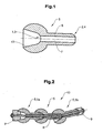
- FIG. 1 shows a longitudinal section of an integral member 5 of a conveyor unit.
- the member 5 is rotationally symmetrical with respect to the symmetry axis of the representation.
- the member 5 has a first joint element 1, which serves as a joint socket 3 is formed, and a second hinge element 2, which is designed as a hinge body 4, on.
- the member 5 has an integral base body 6, on which the joint socket 3 and the joint body 4 are formed.
- the socket 3 and the joint body 4 are formed corresponding to each other, ie they have inner and outer spherical surfaces with the same radius, so that they form a ball joint.
- a joint body 4 of a limb is inserted into the joint socket 3 of a subsequent member.
- the socket 3 in each case passes into an inner cone 13, which limits the mobility of the inserted joint body 4 in the joint to a certain angle.
- An outer surface of the socket 3 is provided for sliding along a guide.
- the first joint element 1 preferably has the shape of a sphere or more generally of a spatial ellipsoid of revolution.
- the second joint element 2 preferably has the shape of a rotary cylinder, which adjoins the first joint element 1 at one end and merges into the joint body 4 at the other end.
- the links 5 are loosely plugged into each other, so they have no snap connection. The links 5 can thus be separated by pulling one another, unless they are pulled against each other by a pulling means.
- Each of the links 5 preferably has a passage opening 7 which runs along the longitudinal axis of the link 5 from the socket 3 to the link body 4.
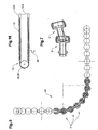
- FIG. 2 shows a conveyor unit 10 having a plurality of such members 5.
- a traction means 8 for example a wire rope or a Kunststoffoffseil is passed through the passage openings 7 of the members 5 and fixed by means of a fastening means 9 to a first member 5a and a last member 5b of the conveyor unit 10 ,
- the traction means 8 is preferably biased, so that the members 5 of the conveyor unit 10 are pressed against each other and held together.
- the bias voltage can be generated by the traction means 8 is elastic, or by the traction means 8 with an elastic attachment to the first or last link 5 is connected (not illustrated). Slight changes in length of the traction device 8, which may occur during the bending of the conveyor unit 10, are compensated by this elasticity.
- FIG. 3 shows a member 5 with a sliding ring 11.
- the sliding ring 11 preferably has a cylindrical inner surface which is slid over a corresponding outer surface of the first joint element 1.
- an annular groove is formed on the first joint element 1, into which a wedge-shaped projection of the sliding ring 11 snaps.
- the wedge on the first hinge element 1 and the groove 11 may be present on the sliding ring.
- the sliding ring 11 is preferably formed of a material which causes a low-friction and low-wear material pairing with the material of a guide channel.
- FIG. 4 shows a conveyor unit with a plurality of such members 5 in a guide rail or a guide channel 12.
- the guide channel 12 may be slotted so that holding elements for objects to be conveyed, which may be attached to one or more of the members 5, through the slot from the guide channel 12th can protrude.
- the guide channel 12 has a substantially circular or elliptical cross section, corresponding to the outer diameter of the links fifth
- FIG. 5 shows an exemplary course of a conveyor unit in a bevel gear.
- the guide channel 12 which surrounds the conveyor unit 10, not drawn. It is thus possible to give a guide channel 12 any spatial course, so that it can be curved in three dimensions. Only the radius of curvature is limited according to the opening angle of the inner cone 13 of the links 5.
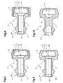
- FIGS. 6 to 10 show further embodiments of links of conveyor units.
- the first and second hinge elements 1, 2 are formed so as to form a snap connection.
- the first and second hinge elements 1, 2 each form ball joints with two concentric balls.
- the smaller bearing surface and spherical surface is defined by a first joint body surface 14 on the joint body 4 and a corresponding first joint socket surface 15 on the joint socket 3.
- the larger bearing surface and spherical surface is defined by a second joint body surface 16 on the joint body 4 and a corresponding second joint socket surface 17 on the joint socket 3.
- the smaller ball section absorbs axial impact forces between the links 5 and centers the links on each other, the larger ball section absorbs axial tensile forces between the links.
- the socket 3 has at an outer end of the second socket surface 17 a socket opening 18, which is larger than the diameter of the first joint body surface 14, but is slightly smaller than the largest diameter of the second joint body surface 16th
- the joint sockets 3 and in particular the links 5 as a whole are preferably made of a technical plastic such as nylon or polyoxymethylene (POM) or polyamide (PA) or polyphenylene sulfide (PPS), or of a filled plastic with inclusions of glass, mineral, etc. or carbon fibers. If the links 5 have inclusions, they are preferably combined with slip rings 11 without inclusions. As a production method for large numbers an injection molding process is provided. This also applies to the links 5 according to the FIGS. 1 to 5 ,
- the sockets 3 are slightly expandable due to the elasticity of the material, and the joint body 4 are a little compressible, so that a snap connection can be produced.
- a transition surface 20 between the first hinge body surface 14 and the second hinge body surface 16 is chamfered, i. it forms a conical surface, wherein the cone with the longitudinal axis of the member 5 is coaxial and its imaginary tip to the second joint member 2 points. When mating two members 5, the transition surface centers the two members and widens the socket opening 18.
- the passage opening 7 leads from the first joint socket surface 15 to the first joint body surface 14.
- the passage opening 7 preferably has an expansion in the form of a feedthrough cone 19 in the region of the first joint body surface 14.
- the transition between the inner surface of the passage opening 7 and the feedthrough cone 19 is rounded (not shown). As a result, a load on a traction device 8 is avoided by bending.
- FIGS. 6 to 8 show variants in which after snapping two members 5, a slide ring 11 is pushed over the respective first joint element 1. As a result, a release of the snap connection is made more difficult.
- FIG. 6 shows a sliding ring 11 with a curved in three dimensions, for example, rotationally ellipsoidal outer surface. This has good mobility in curved conveyor paths.
- FIG. 8 shows a member 5 with a sliding ring 11 with a mainly cylindrical outer surface.
- This member 5 is characterized in a cylindrical guide channel 12, which has only a slightly larger diameter than the slide ring 11, stabilized in the axial direction.
- the guide channel 12 must have a slightly larger diameter than in straight sections in curved areas in order to allow the bending of the links 5 which is necessary in the curves.
- the slip rings 11 are analogous to the embodiment of FIG. 3 engaged.
- FIG. 7 shows two nested members 5 according to the variant of FIG. 6 , with a maximum angle of 15 ° between the axial directions of the links 5. At this angle, the walls of the feedthrough cone 19 of the one member are aligned with the passage opening 7 of the adjoining member 5.
- FIG. 9 shows a member 5 without slide ring 11.
- An outer surface of the socket 3 thus forms a sliding surface on which the member 5 slides through the guide channel 12.
- the remaining properties are analogous to the other snap-in members 5.
- FIG. 10 shows a member 5 without passage opening.
- an opening which partially leads into the base body 6 in the axial direction for example a blind hole, is provided.
- This opening extends along the area of the second hinge element 2, so that its compression is facilitated for snapping the links together.
- such an opening may also be combined with the other embodiments.
- FIG. 11 shows a transmission, which by combining members 5 according to the embodiment of FIG. 1 is realized, but also with the other members 5 according to the Figures 3 or 6 to 10 is feasible.
- the members 5 are guided around drive means 21 and driven means 22, which are formed here by gears.
- the conveyor system of FIG. 11 is not part of the invention. Alternatively, they can also be realized by drives as shown in the following figures.
- the function of drive means 21 and output means 22 can, of course, depending on where a drive is arranged, be reversed.
- the section between drive means 21 and driven means 22 can, as in the FIG. 5 shown to be led to any corners.
- the axial directions of the drive means 21 and output means 22 can thus be skewed to each other at an arbitrary angle.
- the links 5 may also be connected to each other by a traction means 8, wherein the traction means 8 is attached to one or more or none of the member 5 and is loadable to train. Depending on whether and on which members 5, the traction means 8 is attached, a series of links 5 tensile forces and shear forces, or only shear forces transmitted.
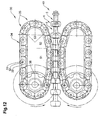
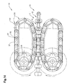
- FIG. 12 shows a drive for conveyor units 10 according to the invention, with a drive unit 30.
- a drive solves the problem that either a wrap of a gear, as in the FIG. 11 , is required, or - in a straight-line course of the conveyor units 10 - the driving force can be initiated only at one point of the conveyor unit 10.
- This drive has a roller element in the sense of WO 2005/113391 A1 or the WO 2005/113392 A1 the same applicant.
- the roller element thus has a roller body 35 which rolls in an orbit 34 and is guided.
- the roller body 35 has a plurality of rollers 31, which are connected to each other or follow each other loosely and are separated by distancing body 33 from each other.
- the spacers 33 preferably form a support for axles 32 of the roller 31 and have, seen in the direction of the rollers 31, in at least one direction, a greater extent than the rollers 31.
- a counter body - in the present case a conveyor unit 10 - roll over the rollers 31 on the circulation path 34, wherein the spacer body 33 prevent successive rollers 31 rub against each other.
- the spacer body 33 have in the direction of front and rear on a cylindrical end face which is coaxial with the roller axes 32.
- the reel body 35 is driven by a roller drive 36, for example a gear which engages in or between the rollers of the roller body 35 driven.
- the distance between the roller axes 32 is equal to the distance between two consecutive members 5.
- the rollers 31 are mounted on either side in a spacer body 33 and engage in a central region of the rollers 31 (in cross-section of the orbit 34, seen in the running direction of the rollers 31) to the members 5 of the conveyor units 10 at.
- the rollers 31 press, for example against radially protruding outer surfaces of the first joint elements. 1
- roller body 35 instead of the roller body 35, there is a roller chain with chain links coupled to one another, the chain links having drivers which engage between the links 5 of the conveyor units 10 and thus transmit a pushing force and / or a tensile force to the conveyor units 10.
- the orbit 34 has a straight, first track portion on which the roller body 35 is guided parallel to the conveyor unit 10 and is in engagement with the conveyor unit 10, and a third track portion on which the roller body 35 is deflected and possibly also driven.
- the third track section is circular, for example.
- a second track section is arranged as a transition. This second track section has a greater radius of curvature than the third, that is, a smaller curvature.
- FIG. 13 shows a cross section through a portion of the drive of FIG. 12 in the area of the conveyed links 5.
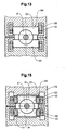
- FIG. 14 shows a further variant of a drive.
- This one is similar to the one of the FIG. 12 constructed, but instead of the distancing body 33 differently shaped second spacer body 37 before.
- These second distancing bodies 37 are connected at a first end to the roller axes 32, ie the roller axles 32 are movable or fixed (depending on how the roller axles 32 are connected to the rollers 31) inserted into the second distancing body 37.
- the second spacers 37 At the first end, the second spacers 37 have an outwardly directed cylindrical surface in the direction of travel, coaxial with the respective roller axis 32.
- the second spacers 37 At the opposite, second end, have an inwardly directed cylindrical surface of the same radius. This encloses the outwardly directed cylindrical surface of the subsequent second spacer body 37.
- successive second spacer body 37 slide against each other as in a cylinder joint.
- FIG. 15 shows a cross section through a portion of the drive of FIG. 14 in the area of the conveyed members 5.
- the rollers 31 are rotatably mounted separately from carriers 39.
- the drivers 39 engage in the gaps between the links 5 and push - depending on the direction of movement - this on the front or rear side of the joint elements.
- Such drivers 39 are of course in the embodiment of FIG. 12 used.
- FIG. 16 schematically shows a conveyor system with a guide channel 12 having an active area 12a, through which a holding means 38 is guided and moved, and a memory channel 12b, in which the part of the conveyor unit 10, which is not in the active area 12a stored.
- the drive 30 is schematically drawn as a wheel, but may also be formed by a drive unit 30 based on a roller body 35.
Landscapes
- Engineering & Computer Science (AREA)
- Mechanical Engineering (AREA)
- General Engineering & Computer Science (AREA)
- Chain Conveyers (AREA)
- Rollers For Roller Conveyors For Transfer (AREA)
- Iron Core Of Rotating Electric Machines (AREA)
- Sampling And Sample Adjustment (AREA)
- Threshing Machine Elements (AREA)
Priority Applications (1)
| Application Number | Priority Date | Filing Date | Title |
|---|---|---|---|
| PL08700531T PL2117971T3 (pl) | 2007-02-01 | 2008-01-28 | System transportowy |
Applications Claiming Priority (2)
| Application Number | Priority Date | Filing Date | Title |
|---|---|---|---|
| CH1712007 | 2007-02-01 | ||
| PCT/CH2008/000026 WO2008092287A2 (de) | 2007-02-01 | 2008-01-28 | Fördersystem, fördereinheit und glied |
Publications (2)
| Publication Number | Publication Date |
|---|---|
| EP2117971A2 EP2117971A2 (de) | 2009-11-18 |
| EP2117971B1 true EP2117971B1 (de) | 2011-09-07 |
Family
ID=38038738
Family Applications (1)
| Application Number | Title | Priority Date | Filing Date |
|---|---|---|---|
| EP08700531A Not-in-force EP2117971B1 (de) | 2007-02-01 | 2008-01-28 | Fördersystem |
Country Status (8)
| Country | Link |
|---|---|
| US (1) | US7975838B2 (pl) |
| EP (1) | EP2117971B1 (pl) |
| AT (1) | ATE523454T1 (pl) |
| AU (1) | AU2008210209B2 (pl) |
| BR (1) | BRPI0807337A2 (pl) |
| CA (1) | CA2676388C (pl) |
| PL (1) | PL2117971T3 (pl) |
| WO (1) | WO2008092287A2 (pl) |
Families Citing this family (12)
| Publication number | Priority date | Publication date | Assignee | Title |
|---|---|---|---|---|
| CH700146A1 (de) * | 2008-12-23 | 2010-06-30 | Wrh Walter Reist Holding Ag | Druckkörper und Fördereinheit. |
| CH701358A1 (de) * | 2009-06-25 | 2010-12-31 | Wrh Walter Reist Holding Ag | Fördereinrichtung und abstützvorrichtung. |
| ES2342532B1 (es) * | 2009-12-29 | 2011-05-20 | Thyssenkrupp Elevator Innovation Center S.A. | Sistema de accionamiento para escaleras y pasillos moviles. |
| CA2801621C (en) * | 2010-06-08 | 2018-02-20 | Boehrer Gmbh | Transport apparatus with moving trucks |
| CH704136A1 (de) | 2010-11-26 | 2012-05-31 | Ferag Ag | Förderkette für ein fördermittel einer fördereinrichtung. |
| EP2664562B1 (de) * | 2012-05-15 | 2015-03-18 | Bühler GmbH | Mitnehmer, Zugelement und Fördereinrichtung zur Förderung von Schüttgut |
| US9718620B2 (en) * | 2013-05-15 | 2017-08-01 | Buehler Gmbh | Method and conveyor device for conveying bulk material |
| US11118397B2 (en) * | 2017-12-20 | 2021-09-14 | Lutron Technology Company Llc | Semi-rigid chain assembly |
| RU2688645C1 (ru) * | 2018-07-19 | 2019-05-21 | Алексей Игоревич Махалин | Устройство для перемещения бесконечных конвейерных цепей |
| US12065877B2 (en) | 2020-01-31 | 2024-08-20 | Lutron Technology Company Llc | Semi-rigid chain for a window treatment |
| CN114506626B (zh) * | 2022-03-09 | 2024-02-23 | 焦作神华重型机械制造有限公司 | 一种采煤用刮板输送机及控制方法 |
| US20240167333A1 (en) * | 2022-11-22 | 2024-05-23 | Hunter Douglas Inc. | Track system for use with an operating element in an architectural-structure covering |
Family Cites Families (16)
| Publication number | Priority date | Publication date | Assignee | Title |
|---|---|---|---|---|
| US1939766A (en) | 1930-11-18 | 1933-12-19 | Corset Lucien Alfred Maurice | Transmission device |
| GB1239050A (pl) * | 1968-12-31 | 1971-07-14 | ||
| CH538065A (de) | 1971-04-30 | 1973-06-15 | Reist Walter | Gliederkette |
| DE2203495A1 (de) * | 1972-01-26 | 1973-08-02 | Babcock & Wilcox Ag | Antrieb von in gleitkanaelen bewegten gelenkketten fuer foerdereinrichtungen |
| US4082173A (en) * | 1976-06-10 | 1978-04-04 | Otis Elevator Company | Drive unit for an endless conveyor |
| CH646762A5 (de) * | 1980-06-06 | 1984-12-14 | Ferag Ag | Kugelgelenk-gliederkette. |
| CA1177727A (en) * | 1981-02-10 | 1984-11-13 | Feramatic Ag | Fluid-actuated drive |
| DE3136335A1 (de) | 1981-09-14 | 1983-04-14 | Repa Feinstanzwerk Gmbh, 7071 Alfdorf | Antriebsvorrichtung zum bewegen des endbeschlages eines passiv-sicherheitsgurtes |
| CH654084A5 (de) * | 1981-10-16 | 1986-01-31 | Feramatic Ag | Antriebseinrichtung mit einer kugelgelenkkette. |
| CH655916A5 (de) | 1982-04-08 | 1986-05-30 | Feramatic Ag | Vorrichtung zum herstellen einer verbindung zwischen jeweils zwei stationen einer mindestens drei stationen aufweisenden anlage. |
| US5103968A (en) * | 1991-01-14 | 1992-04-14 | Skarlupka Joseph H | Parallel centerline chain drive |
| DE59701855D1 (de) | 1996-09-25 | 2000-07-13 | Ipt Weinfelden Ag Weinfelden | Kraftübertragungsmittel zum übertragen von schubkräften |
| DE19912491A1 (de) * | 1999-03-19 | 2000-09-28 | Multivac Haggenmueller Gmbh | Verpackungsmaschine |
| ITMI991268A1 (it) * | 1999-06-08 | 2000-12-08 | Luciano Migliori | Dispositivo di comando tira e spingi ad elementi articolati |
| DE10240487B4 (de) | 2002-09-03 | 2018-02-22 | Otmar Fahrion | Kette |
| CH703149B1 (de) * | 2004-05-21 | 2011-11-30 | Wrh Walter Reist Holding Ag | Rollenantriebselement. |
-
2008
- 2008-01-28 PL PL08700531T patent/PL2117971T3/pl unknown
- 2008-01-28 BR BRPI0807337-6A patent/BRPI0807337A2/pt not_active IP Right Cessation
- 2008-01-28 US US12/525,375 patent/US7975838B2/en not_active Expired - Fee Related
- 2008-01-28 WO PCT/CH2008/000026 patent/WO2008092287A2/de not_active Ceased
- 2008-01-28 AU AU2008210209A patent/AU2008210209B2/en not_active Ceased
- 2008-01-28 CA CA2676388A patent/CA2676388C/en not_active Expired - Fee Related
- 2008-01-28 AT AT08700531T patent/ATE523454T1/de active
- 2008-01-28 EP EP08700531A patent/EP2117971B1/de not_active Not-in-force
Also Published As
| Publication number | Publication date |
|---|---|
| EP2117971A2 (de) | 2009-11-18 |
| BRPI0807337A2 (pt) | 2014-05-20 |
| US20100072029A1 (en) | 2010-03-25 |
| US7975838B2 (en) | 2011-07-12 |
| CA2676388C (en) | 2015-10-13 |
| WO2008092287A3 (de) | 2008-11-06 |
| AU2008210209B2 (en) | 2012-09-20 |
| ATE523454T1 (de) | 2011-09-15 |
| PL2117971T3 (pl) | 2012-04-30 |
| WO2008092287A2 (de) | 2008-08-07 |
| AU2008210209A1 (en) | 2008-08-07 |
| CA2676388A1 (en) | 2008-08-07 |
Similar Documents
| Publication | Publication Date | Title |
|---|---|---|
| EP2117971B1 (de) | Fördersystem | |
| EP2248946B1 (de) | Verbindungselement für Laufschienen | |
| EP2163494B1 (de) | Rollenelement | |
| EP2289823B1 (de) | Stützvorrichtung für eine Fördereinrichtung und Verfahren zum Betrieb einer Fördereinrichtung | |
| EP2877100A1 (de) | Schaft für medizinisches instrument mit beweglichen abschnitten | |
| EP2123577B1 (de) | Angetriebenes Rollenelement | |
| EP2181021B1 (de) | Antriebseinrichtung zur erzeugung einer gurtstraffbewegung in einer sicherheitsgurtvorrichtung | |
| EP1412265B1 (de) | Staufähiges kurvenelement für ein transfersystem | |
| EP2455307A1 (de) | Eingriffsschutz für Rollenförderer | |
| WO2012068695A1 (de) | Fördereinrichtung | |
| EP2210831A1 (de) | Fördervorrichtung und Förderkörper | |
| EP1084071A1 (de) | Antriebsrolle | |
| EP2110344B1 (de) | Fördervorrichtung mit Schubelement | |
| EP0928275B1 (de) | Kraftübertragungsmittel zum übertragen von schubkräften | |
| EP1858782B1 (de) | Rollenkörper und verfahren zum herstellen eines rollenkörpers | |
| DE20305680U1 (de) | Kabelführung | |
| EP1849723B1 (de) | Förderkette | |
| EP2202181A1 (de) | Förderglied | |
| DE102005059516A1 (de) | Wälzkörperkette mit mehrteiligem Kettenkörper sowie Kettenkörperteil für eine Wälzkörperkette | |
| DE202016001710U1 (de) | Ausgleichskupplung | |
| DE3934378A1 (de) | Fahrgurtfoerderer | |
| DE102010014913A1 (de) | Bolzenfixierung einer Förderkette |
Legal Events
| Date | Code | Title | Description |
|---|---|---|---|
| PUAI | Public reference made under article 153(3) epc to a published international application that has entered the european phase |
Free format text: ORIGINAL CODE: 0009012 |
|
| 17P | Request for examination filed |
Effective date: 20090727 |
|
| AK | Designated contracting states |
Kind code of ref document: A2 Designated state(s): AT BE BG CH CY CZ DE DK EE ES FI FR GB GR HR HU IE IS IT LI LT LU LV MC MT NL NO PL PT RO SE SI SK TR |
|
| DAX | Request for extension of the european patent (deleted) | ||
| 17Q | First examination report despatched |
Effective date: 20100707 |
|
| GRAP | Despatch of communication of intention to grant a patent |
Free format text: ORIGINAL CODE: EPIDOSNIGR1 |
|
| RTI1 | Title (correction) |
Free format text: CONVEYING SYSTEM |
|
| GRAS | Grant fee paid |
Free format text: ORIGINAL CODE: EPIDOSNIGR3 |
|
| GRAA | (expected) grant |
Free format text: ORIGINAL CODE: 0009210 |
|
| REG | Reference to a national code |
Ref country code: GB Ref legal event code: FG4D Free format text: NOT ENGLISH |
|
| REG | Reference to a national code |
Ref country code: CH Ref legal event code: EP |
|
| REG | Reference to a national code |
Ref country code: IE Ref legal event code: FG4D Free format text: LANGUAGE OF EP DOCUMENT: GERMAN |
|
| REG | Reference to a national code |
Ref country code: CH Ref legal event code: NV Representative=s name: FREI PATENTANWALTSBUERO AG |
|
| REG | Reference to a national code |
Ref country code: DE Ref legal event code: R096 Ref document number: 502008004769 Country of ref document: DE Effective date: 20111124 |
|
| REG | Reference to a national code |
Ref country code: NL Ref legal event code: VDEP Effective date: 20110907 |
|
| PG25 | Lapsed in a contracting state [announced via postgrant information from national office to epo] |
Ref country code: FI Free format text: LAPSE BECAUSE OF FAILURE TO SUBMIT A TRANSLATION OF THE DESCRIPTION OR TO PAY THE FEE WITHIN THE PRESCRIBED TIME-LIMIT Effective date: 20110907 Ref country code: SE Free format text: LAPSE BECAUSE OF FAILURE TO SUBMIT A TRANSLATION OF THE DESCRIPTION OR TO PAY THE FEE WITHIN THE PRESCRIBED TIME-LIMIT Effective date: 20110907 Ref country code: NO Free format text: LAPSE BECAUSE OF FAILURE TO SUBMIT A TRANSLATION OF THE DESCRIPTION OR TO PAY THE FEE WITHIN THE PRESCRIBED TIME-LIMIT Effective date: 20111207 Ref country code: LT Free format text: LAPSE BECAUSE OF FAILURE TO SUBMIT A TRANSLATION OF THE DESCRIPTION OR TO PAY THE FEE WITHIN THE PRESCRIBED TIME-LIMIT Effective date: 20110907 Ref country code: HR Free format text: LAPSE BECAUSE OF FAILURE TO SUBMIT A TRANSLATION OF THE DESCRIPTION OR TO PAY THE FEE WITHIN THE PRESCRIBED TIME-LIMIT Effective date: 20110907 |
|
| LTIE | Lt: invalidation of european patent or patent extension |
Effective date: 20110907 |
|
| PG25 | Lapsed in a contracting state [announced via postgrant information from national office to epo] |
Ref country code: LV Free format text: LAPSE BECAUSE OF FAILURE TO SUBMIT A TRANSLATION OF THE DESCRIPTION OR TO PAY THE FEE WITHIN THE PRESCRIBED TIME-LIMIT Effective date: 20110907 Ref country code: GR Free format text: LAPSE BECAUSE OF FAILURE TO SUBMIT A TRANSLATION OF THE DESCRIPTION OR TO PAY THE FEE WITHIN THE PRESCRIBED TIME-LIMIT Effective date: 20111208 Ref country code: CY Free format text: LAPSE BECAUSE OF FAILURE TO SUBMIT A TRANSLATION OF THE DESCRIPTION OR TO PAY THE FEE WITHIN THE PRESCRIBED TIME-LIMIT Effective date: 20110907 Ref country code: SI Free format text: LAPSE BECAUSE OF FAILURE TO SUBMIT A TRANSLATION OF THE DESCRIPTION OR TO PAY THE FEE WITHIN THE PRESCRIBED TIME-LIMIT Effective date: 20110907 |
|
| REG | Reference to a national code |
Ref country code: IE Ref legal event code: FD4D |
|
| PG25 | Lapsed in a contracting state [announced via postgrant information from national office to epo] |
Ref country code: IS Free format text: LAPSE BECAUSE OF FAILURE TO SUBMIT A TRANSLATION OF THE DESCRIPTION OR TO PAY THE FEE WITHIN THE PRESCRIBED TIME-LIMIT Effective date: 20120107 Ref country code: SK Free format text: LAPSE BECAUSE OF FAILURE TO SUBMIT A TRANSLATION OF THE DESCRIPTION OR TO PAY THE FEE WITHIN THE PRESCRIBED TIME-LIMIT Effective date: 20110907 Ref country code: CZ Free format text: LAPSE BECAUSE OF FAILURE TO SUBMIT A TRANSLATION OF THE DESCRIPTION OR TO PAY THE FEE WITHIN THE PRESCRIBED TIME-LIMIT Effective date: 20110907 Ref country code: IE Free format text: LAPSE BECAUSE OF FAILURE TO SUBMIT A TRANSLATION OF THE DESCRIPTION OR TO PAY THE FEE WITHIN THE PRESCRIBED TIME-LIMIT Effective date: 20110907 |
|
| REG | Reference to a national code |
Ref country code: PL Ref legal event code: T3 |
|
| PG25 | Lapsed in a contracting state [announced via postgrant information from national office to epo] |
Ref country code: RO Free format text: LAPSE BECAUSE OF FAILURE TO SUBMIT A TRANSLATION OF THE DESCRIPTION OR TO PAY THE FEE WITHIN THE PRESCRIBED TIME-LIMIT Effective date: 20110907 Ref country code: EE Free format text: LAPSE BECAUSE OF FAILURE TO SUBMIT A TRANSLATION OF THE DESCRIPTION OR TO PAY THE FEE WITHIN THE PRESCRIBED TIME-LIMIT Effective date: 20110907 Ref country code: NL Free format text: LAPSE BECAUSE OF FAILURE TO SUBMIT A TRANSLATION OF THE DESCRIPTION OR TO PAY THE FEE WITHIN THE PRESCRIBED TIME-LIMIT Effective date: 20110907 Ref country code: PT Free format text: LAPSE BECAUSE OF FAILURE TO SUBMIT A TRANSLATION OF THE DESCRIPTION OR TO PAY THE FEE WITHIN THE PRESCRIBED TIME-LIMIT Effective date: 20120109 |
|
| PLBE | No opposition filed within time limit |
Free format text: ORIGINAL CODE: 0009261 |
|
| STAA | Information on the status of an ep patent application or granted ep patent |
Free format text: STATUS: NO OPPOSITION FILED WITHIN TIME LIMIT |
|
| PG25 | Lapsed in a contracting state [announced via postgrant information from national office to epo] |
Ref country code: DK Free format text: LAPSE BECAUSE OF FAILURE TO SUBMIT A TRANSLATION OF THE DESCRIPTION OR TO PAY THE FEE WITHIN THE PRESCRIBED TIME-LIMIT Effective date: 20110907 |
|
| 26N | No opposition filed |
Effective date: 20120611 |
|
| PG25 | Lapsed in a contracting state [announced via postgrant information from national office to epo] |
Ref country code: MC Free format text: LAPSE BECAUSE OF NON-PAYMENT OF DUE FEES Effective date: 20120131 |
|
| REG | Reference to a national code |
Ref country code: DE Ref legal event code: R097 Ref document number: 502008004769 Country of ref document: DE Effective date: 20120611 |
|
| PG25 | Lapsed in a contracting state [announced via postgrant information from national office to epo] |
Ref country code: ES Free format text: LAPSE BECAUSE OF FAILURE TO SUBMIT A TRANSLATION OF THE DESCRIPTION OR TO PAY THE FEE WITHIN THE PRESCRIBED TIME-LIMIT Effective date: 20111218 |
|
| PG25 | Lapsed in a contracting state [announced via postgrant information from national office to epo] |
Ref country code: BG Free format text: LAPSE BECAUSE OF FAILURE TO SUBMIT A TRANSLATION OF THE DESCRIPTION OR TO PAY THE FEE WITHIN THE PRESCRIBED TIME-LIMIT Effective date: 20111207 |
|
| PG25 | Lapsed in a contracting state [announced via postgrant information from national office to epo] |
Ref country code: MT Free format text: LAPSE BECAUSE OF FAILURE TO SUBMIT A TRANSLATION OF THE DESCRIPTION OR TO PAY THE FEE WITHIN THE PRESCRIBED TIME-LIMIT Effective date: 20110907 |
|
| PG25 | Lapsed in a contracting state [announced via postgrant information from national office to epo] |
Ref country code: TR Free format text: LAPSE BECAUSE OF FAILURE TO SUBMIT A TRANSLATION OF THE DESCRIPTION OR TO PAY THE FEE WITHIN THE PRESCRIBED TIME-LIMIT Effective date: 20110907 |
|
| PG25 | Lapsed in a contracting state [announced via postgrant information from national office to epo] |
Ref country code: LU Free format text: LAPSE BECAUSE OF NON-PAYMENT OF DUE FEES Effective date: 20120128 |
|
| PGFP | Annual fee paid to national office [announced via postgrant information from national office to epo] |
Ref country code: PL Payment date: 20140103 Year of fee payment: 7 |
|
| PG25 | Lapsed in a contracting state [announced via postgrant information from national office to epo] |
Ref country code: HU Free format text: LAPSE BECAUSE OF FAILURE TO SUBMIT A TRANSLATION OF THE DESCRIPTION OR TO PAY THE FEE WITHIN THE PRESCRIBED TIME-LIMIT Effective date: 20080128 |
|
| REG | Reference to a national code |
Ref country code: DE Ref legal event code: R082 Ref document number: 502008004769 Country of ref document: DE Representative=s name: PATENTANWAELTE UND RECHTSANWALT DR. WEISS, ARA, DE Ref country code: DE Ref legal event code: R082 Ref document number: 502008004769 Country of ref document: DE Representative=s name: PATENTANWAELTE UND RECHTSANWALT WEISS, ARAT & , DE |
|
| REG | Reference to a national code |
Ref country code: FR Ref legal event code: PLFP Year of fee payment: 9 |
|
| PGFP | Annual fee paid to national office [announced via postgrant information from national office to epo] |
Ref country code: CH Payment date: 20151215 Year of fee payment: 9 |
|
| PGFP | Annual fee paid to national office [announced via postgrant information from national office to epo] |
Ref country code: DE Payment date: 20160120 Year of fee payment: 9 Ref country code: IT Payment date: 20160127 Year of fee payment: 9 |
|
| PG25 | Lapsed in a contracting state [announced via postgrant information from national office to epo] |
Ref country code: PL Free format text: LAPSE BECAUSE OF NON-PAYMENT OF DUE FEES Effective date: 20150128 |
|
| PGFP | Annual fee paid to national office [announced via postgrant information from national office to epo] |
Ref country code: AT Payment date: 20160121 Year of fee payment: 9 Ref country code: FR Payment date: 20160121 Year of fee payment: 9 Ref country code: BE Payment date: 20160120 Year of fee payment: 9 Ref country code: GB Payment date: 20160120 Year of fee payment: 9 |
|
| PG25 | Lapsed in a contracting state [announced via postgrant information from national office to epo] |
Ref country code: BE Free format text: LAPSE BECAUSE OF NON-PAYMENT OF DUE FEES Effective date: 20170131 |
|
| REG | Reference to a national code |
Ref country code: DE Ref legal event code: R119 Ref document number: 502008004769 Country of ref document: DE |
|
| REG | Reference to a national code |
Ref country code: CH Ref legal event code: PL |
|
| REG | Reference to a national code |
Ref country code: AT Ref legal event code: MM01 Ref document number: 523454 Country of ref document: AT Kind code of ref document: T Effective date: 20170128 |
|
| GBPC | Gb: european patent ceased through non-payment of renewal fee |
Effective date: 20170128 |
|
| REG | Reference to a national code |
Ref country code: FR Ref legal event code: ST Effective date: 20170929 |
|
| PG25 | Lapsed in a contracting state [announced via postgrant information from national office to epo] |
Ref country code: AT Free format text: LAPSE BECAUSE OF NON-PAYMENT OF DUE FEES Effective date: 20170128 Ref country code: CH Free format text: LAPSE BECAUSE OF NON-PAYMENT OF DUE FEES Effective date: 20170131 Ref country code: FR Free format text: LAPSE BECAUSE OF NON-PAYMENT OF DUE FEES Effective date: 20170131 Ref country code: LI Free format text: LAPSE BECAUSE OF NON-PAYMENT OF DUE FEES Effective date: 20170131 |
|
| PG25 | Lapsed in a contracting state [announced via postgrant information from national office to epo] |
Ref country code: GB Free format text: LAPSE BECAUSE OF NON-PAYMENT OF DUE FEES Effective date: 20170128 Ref country code: DE Free format text: LAPSE BECAUSE OF NON-PAYMENT OF DUE FEES Effective date: 20170801 |
|
| REG | Reference to a national code |
Ref country code: BE Ref legal event code: MM Effective date: 20170131 |
|
| PG25 | Lapsed in a contracting state [announced via postgrant information from national office to epo] |
Ref country code: IT Free format text: LAPSE BECAUSE OF NON-PAYMENT OF DUE FEES Effective date: 20170128 |