EP2117807B1 - Blasdüse für eine behälterherstellungsmaschine - Google Patents
Blasdüse für eine behälterherstellungsmaschine Download PDFInfo
- Publication number
- EP2117807B1 EP2117807B1 EP08761847.6A EP08761847A EP2117807B1 EP 2117807 B1 EP2117807 B1 EP 2117807B1 EP 08761847 A EP08761847 A EP 08761847A EP 2117807 B1 EP2117807 B1 EP 2117807B1
- Authority
- EP
- European Patent Office
- Prior art keywords
- nozzle
- insert
- blank
- mold
- preform
- Prior art date
- Legal status (The legal status is an assumption and is not a legal conclusion. Google has not performed a legal analysis and makes no representation as to the accuracy of the status listed.)
- Not-in-force
Links
- 238000000071 blow moulding Methods 0.000 claims description 9
- 238000004519 manufacturing process Methods 0.000 claims description 8
- 239000004033 plastic Substances 0.000 claims description 6
- 229920003023 plastic Polymers 0.000 claims description 6
- 230000002093 peripheral effect Effects 0.000 claims description 5
- 238000000465 moulding Methods 0.000 claims description 4
- 230000006835 compression Effects 0.000 claims description 3
- 238000007906 compression Methods 0.000 claims description 3
- 230000037431 insertion Effects 0.000 claims 1
- 238000003780 insertion Methods 0.000 claims 1
- 238000007664 blowing Methods 0.000 description 11
- 238000006073 displacement reaction Methods 0.000 description 3
- 238000000034 method Methods 0.000 description 3
- 230000008901 benefit Effects 0.000 description 2
- 238000010438 heat treatment Methods 0.000 description 2
- 239000000463 material Substances 0.000 description 2
- 230000035939 shock Effects 0.000 description 2
- 241001080024 Telles Species 0.000 description 1
- 238000002474 experimental method Methods 0.000 description 1
- 230000009477 glass transition Effects 0.000 description 1
- 230000036244 malformation Effects 0.000 description 1
- 229920001296 polysiloxane Polymers 0.000 description 1
- 230000000306 recurrent effect Effects 0.000 description 1
- 230000000007 visual effect Effects 0.000 description 1
Images





Classifications
-
- B—PERFORMING OPERATIONS; TRANSPORTING
- B29—WORKING OF PLASTICS; WORKING OF SUBSTANCES IN A PLASTIC STATE IN GENERAL
- B29C—SHAPING OR JOINING OF PLASTICS; SHAPING OF MATERIAL IN A PLASTIC STATE, NOT OTHERWISE PROVIDED FOR; AFTER-TREATMENT OF THE SHAPED PRODUCTS, e.g. REPAIRING
- B29C49/00—Blow-moulding, i.e. blowing a preform or parison to a desired shape within a mould; Apparatus therefor
- B29C49/42—Component parts, details or accessories; Auxiliary operations
- B29C49/58—Blowing means
-
- B—PERFORMING OPERATIONS; TRANSPORTING
- B29—WORKING OF PLASTICS; WORKING OF SUBSTANCES IN A PLASTIC STATE IN GENERAL
- B29C—SHAPING OR JOINING OF PLASTICS; SHAPING OF MATERIAL IN A PLASTIC STATE, NOT OTHERWISE PROVIDED FOR; AFTER-TREATMENT OF THE SHAPED PRODUCTS, e.g. REPAIRING
- B29C49/00—Blow-moulding, i.e. blowing a preform or parison to a desired shape within a mould; Apparatus therefor
- B29C49/42—Component parts, details or accessories; Auxiliary operations
- B29C49/58—Blowing means
- B29C2049/5827—Blowing means not touching the preform
-
- B—PERFORMING OPERATIONS; TRANSPORTING
- B29—WORKING OF PLASTICS; WORKING OF SUBSTANCES IN A PLASTIC STATE IN GENERAL
- B29C—SHAPING OR JOINING OF PLASTICS; SHAPING OF MATERIAL IN A PLASTIC STATE, NOT OTHERWISE PROVIDED FOR; AFTER-TREATMENT OF THE SHAPED PRODUCTS, e.g. REPAIRING
- B29C2949/00—Indexing scheme relating to blow-moulding
- B29C2949/07—Preforms or parisons characterised by their configuration
- B29C2949/0715—Preforms or parisons characterised by their configuration the preform having one end closed
-
- B—PERFORMING OPERATIONS; TRANSPORTING
- B29—WORKING OF PLASTICS; WORKING OF SUBSTANCES IN A PLASTIC STATE IN GENERAL
- B29C—SHAPING OR JOINING OF PLASTICS; SHAPING OF MATERIAL IN A PLASTIC STATE, NOT OTHERWISE PROVIDED FOR; AFTER-TREATMENT OF THE SHAPED PRODUCTS, e.g. REPAIRING
- B29C49/00—Blow-moulding, i.e. blowing a preform or parison to a desired shape within a mould; Apparatus therefor
- B29C49/02—Combined blow-moulding and manufacture of the preform or the parison
- B29C49/06—Injection blow-moulding
-
- B—PERFORMING OPERATIONS; TRANSPORTING
- B29—WORKING OF PLASTICS; WORKING OF SUBSTANCES IN A PLASTIC STATE IN GENERAL
- B29C—SHAPING OR JOINING OF PLASTICS; SHAPING OF MATERIAL IN A PLASTIC STATE, NOT OTHERWISE PROVIDED FOR; AFTER-TREATMENT OF THE SHAPED PRODUCTS, e.g. REPAIRING
- B29C49/00—Blow-moulding, i.e. blowing a preform or parison to a desired shape within a mould; Apparatus therefor
- B29C49/28—Blow-moulding apparatus
- B29C49/30—Blow-moulding apparatus having movable moulds or mould parts
- B29C49/36—Blow-moulding apparatus having movable moulds or mould parts rotatable about one axis
Definitions
- the invention relates to the field of the manufacture of containers, by blow molding or stretch blow molding.
- the blowing of the containers takes place in a mold defining a cavity into which is introduced a plastic blank preheated so as to soften the material (the term "blank" is intended not only a preform but also an intermediate container having undergone one or more prior blowing), this blank being then pressurized to give it a predetermined shape corresponding to that of the cavity.
- the introduction of a gas into the blank is via a nozzle which, after the blank has been introduced into the cavity through an opening in the mold, is applied in a sealed manner against an upper face. of it.
- the nozzle which covers the neck of the blank protruding from the mold, is generally called "bell nozzle”.
- the invention aims in particular to overcome the aforementioned drawbacks of known techniques, by proposing a solution to improve the average quality of the containers.
- the invention proposes, according to a first object, a nozzle for a machine for blowing or stretching containers from plastic blanks according to claim 1.
- the bearing face has, for example, with respect to a plane perpendicular to an axis of displacement of the insert, an opening angle of between about 10 ° and about 60 °,
- the bearing face of the insert has a flat central portion (which has an outer diameter preferably greater than or equal to the diameter of the rim of the blank), radially extended by a frustoconical peripheral portion.
- the nozzle body defines an end stop of the insert in the down position.
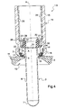
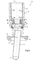
- FIG. 1 to 8 is partially shown a machine 1 for manufacturing containers by blow molding or stretching from blanks 2 of plastic such as PET. Although it may just as well be an intermediate container having undergone at least one prior blowing, we assume in what follows that the blank 2 considered is a preform having simply undergone a heating operation at a higher temperature. at its glass transition temperature.
- the preform 2 comprises a neck 3, which remains substantially unchanged during the blowing and has at an upper end a rim 4 of circular shape.
- the neck 3 is extended, below a flange 5 to ensure the lift of the preform 2 during the manufacturing steps (heating, blowing) of the container, by a body 6 substantially cylindrical closed at a lower end by a hemispherical cap 7.
- the machine 1 comprises a plurality of molding units 8 of which only one is shown in the figures.
- This unit 8 comprises a mold 9 dug a cavity 10 defining the final shape of the container.
- the mold 9 has an upper face 11 on which the cavity 10 opens out through a circular opening 12 through which the preform 2 is introduced into the mold 9 .
- the opening is provided with a counterbore 13 in which is wedged the flange 5 of the preform 2 when it is normally inserted into the mold 9 ( figure 4 ).
- the molding unit 8 further comprises a bell-shaped nozzle 14 mounted movably, in the axis of the mold 9 , between a high position where it is spaced from the upper face 11 of the mold 9 to allow the introduction of the preform 2 into the mold. it, and a low position where it is applied against the upper face 11 .
- the nozzle 14 comprises a tubular nozzle body 15 which, when the manufacture of the container includes a drawing operation, is traversed by a sliding elongation rod (not shown).
- the nozzle body 15 is shaped into a threaded tip 16 on which is mounted an annular seal 17 (made of a flexible material such as rubber - natural or synthetic - or silicone) whose fixing is ensured. by a ring 18 screwed on the tip 16 with interposition, between the seal 17 and the tip 16 , a washer 19 .
- the nozzle 14 is further equipped with an insert 20 coaxially mounted in the nozzle body 15 near its lower end.
- the insert 20 has a substantially tubular upper portion 21 , which is extended by an annular lower portion 22 extending radially projecting from the upper portion 21 .
- the insert 20 is mounted in a bore 23 formed in the nozzle body 15 .
- This bore 23 has an inside diameter slightly greater than the overall diameter (corresponding to the outside diameter of the annular lower portion 22 ) of the insert 20 , so as to allow the axial displacement thereof in the bore 23 .
- the bore 23 is limited, on the lower side, by a shoulder 24 and is extended, on the opposite side, by a bore 25 from which it is separated by a counterbore 26 .
- a washer 27 is further mounted in the bore 25 while being pressed against the counterbore 26 by means of a tubular jacket 28 fitted into the bore 25 and fixed thereto by screwing (or any other equivalent means). .
- the washer 27 has a central hole 29 through which passes, with clearance, the tubular upper portion 21 of the insert 20 .
- a return spring 30 operating in compression, is mounted around the upper portion 21 and is interposed between the washer 27 and the annular portion 22 of the insert 20 .
- the return spring 30 permanently urges the insert 20 towards its lower position. When fully compressed, the spring 30 also forms a limit stop of the insert 20 in the high position.
- the insert 20 has, at a lower end, a bearing face 31 adapted to cooperate with the rim 4 of the preform 2 to, thanks to the restoring force exerted by the spring 30 , press the preform 2 against the face 11 upper mold 9 and minimize the risk that it adopts an off-axis position during blowing.
- the preform 2 On leaving the oven, the preform 2 is brought into line with the opening 12 and then released into the mold 9 .
- the figures 2 and 6 illustrate a situation that occurs frequently: the preform 2 bounces against the upper face 11 of the mold 9 , against the opening 12 and / or the countersink 13 and thus tends to offset.
- the nozzle 14 drops rapidly to come in the lower position to press against the mold 9 for blowing, it can happen that down the nozzle 14 blocks the preform 2 in an off-axis position, with the flange 5 to horse on the edge of the facing 13 .
- the insert 20 bearing against the rim 4 of the preform 2 , is slightly spaced from the shoulder 24 , so that the preform 2 is permanently pressed against the mold 9 .
- This is allowed by the choice of dimensions of the nozzle 14 . More specifically, the distance separating the bearing face 31 from the lower face of the seal 17 (by which it bears against the upper face 11 of the mold 9 ) is smaller than the height of the neck 3 .
- the bearing face 31 is flat, being perpendicular to the axis A of revolution of the insert 20 (which axis coincides with the axis of displacement of the insert 20 , itself coincident with the axis of the nozzle 14 ).
- the bearing face 31 is frustoconical of revolution about the axis A of the insert 20 .
- the opening angle of the bearing face 31 of the insert 20 relative to a plane perpendicular to the axis A of the insert 20 is left to the free choice of the skilled person. This one can look for a good compromise between the force with which the preform 2 is pressed against the mold 9 (force provided by an open angle, which maximizes the axial component of the force exerted by the insert 20 on the preform 2 ) and the centering of the preform 2 (provided by a closed angle, which maximizes the radial component of the force exerted by the insert 20 on the preform 2 ).
- the opening angle ⁇ will preferably be between about 10 ° (corresponding to the first case) and about 60 ° (corresponding to the second case). In the example shown on the Figures 5 to 8 the opening angle of the bearing face 31 is about 20 °.
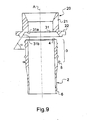
- the bearing face 31 combines a flat portion and a frustoconical portion. More specifically, the bearing face 31 has a planar central portion 31a , whose outer diameter is greater than or equal to the diameter of the rim 4 and which is extended by a frustoconical peripheral portion 31b whose opening angle will be selected from the described above. In the example shown on the figure 9 the opening angle of the frustoconical peripheral portion 31b is approximately 60 °.
- the action of the insert 20 on the preform 2 is performed in two stages: a first time corresponding to the centering of the preform 2 during the descent of the nozzle 14 , when the rim 4 of the offset preform 2 comes, after bouncing against the mold 9 , in contact with the frustoconical peripheral portion 31b , then a second time when, once the preform 2 stabilized and recentered in the axis of the mold 9 , the insert 20 keeps it pressed against the face 11 top thereof through the portion 31 has planar central.
- the inventors have found that the presence of the insert 20 drastically reduces the proportion of off-set preforms during blowing. This results in a lower scrap rate and improved average quality of the blown containers.
Landscapes
- Engineering & Computer Science (AREA)
- Manufacturing & Machinery (AREA)
- Mechanical Engineering (AREA)
- Blow-Moulding Or Thermoforming Of Plastics Or The Like (AREA)
- Lining Or Joining Of Plastics Or The Like (AREA)
- Moulds For Moulding Plastics Or The Like (AREA)
Claims (8)
- Düse (14) für eine Maschine (1) zum Blasen oder Strecken-Blasen von Behältern ausgehend von Rohlingen (2) aus Kunststoff, wobei diese Düse (14) Folgendes aufweist:- einen Düsenkörper (15), der gegen eine obere Fläche (11) einer Form (9), die dazu bestimmt ist, einen Rohling (2) aufzunehmen, in Auflage kommen kann,- einen Einsatz (20), der mit einer Auflagefläche (31) versehen ist, die geeignet ist, mit einer Öffnungskontur (4) des Rohlings (2) zusammenzuwirken, wobei dieser Einsatz (20) in dem Düsenkörper (15) zwischen einer Hochstellung und einer Tiefstellung beweglich installiert ist, und- ein Rückhalteorgan (30), das den Einsatz (20) zu seiner Tiefstellung zurückholt, dadurch gekennzeichnet, dass die Auflagefläche (31) des Einsatzes (20) kegelstumpfförmig ist.
- Düse (14) nach Anspruch 1, dadurch gekennzeichnet, dass die kegelstumpfförmige Auflagefläche (31) geeignet ist, mit einem äußeren Rand der Öffnungskontur (4) des Rohlings (2) in Berührung zu kommen.
- Düse (14) nach Anspruch 1 oder 2, dadurch gekennzeichnet, dass die kegelstumpfförmige Auflagefläche (31) in Bezug zu einer Ebene senkrecht zu einer Verlagerungsachse (A) des Einsatzes (20) einen Öffnungswinkel (α) zwischen etwa 10° und etwa 60° aufweist.
- Düse (14) nach einem der Ansprüche, dadurch gekennzeichnet, dass die Auflagefläche (31) einen ebenen zentralen Abschnitt (31a) aufweist, der sich durch einen kegelstumpfförmigen peripheren Abschnitt (31b) verlängert.
- Düse (14) nach Anspruch 4, dadurch gekennzeichnet, dass der ebene zentrale Abschnitt (31a) einen Außendurchmesser aufweist, der größer oder gleich dem Durchmesser der Öffnungskontur (4) des Rohlings (2) ist.
- Düse (14) nach einem der Ansprüche 1 bis 5, dadurch gekennzeichnet, dass der Düsenkörper (15) einen Ansatz (24) definiert, der einen Hubendanschlag des Einsatzes (20) in Tiefstellung bildet.
- Düse (14) nach einem der Ansprüche 1 bis 6, dadurch gekennzeichnet, dass das Rückholorgan (30) eine Druckfeder ist.
- Maschine (1) zum Herstellen von Behältern durch Blasen oder Strecken-Blasen ausgehend von Rohlingen (2) aus Kunststoff, die Folgendes aufweist:- wenigstens eine Formeinheit (8), die mit einer Form (9) versehen ist, die dazu bestimmt ist, einen Rohling (2) aufzunehmen, und- eine Düse (14) nach einem der Ansprüche 1 bis 7, die zwischen einer Hochstellung, in der sie von einer oberen Fläche (11) der Form (9) beabstandet ist, um das Einführen des Rohlings (2) in die Form (9) zu erlauben, und einer Tiefstellung, in der sie gegen die obere Fläche (11) der Form (9) angelegt ist, beweglich installiert ist.
Applications Claiming Priority (2)
| Application Number | Priority Date | Filing Date | Title |
|---|---|---|---|
| FR0701130A FR2912678B1 (fr) | 2007-02-16 | 2007-02-16 | Tuyere pour une machine de fabrication de recipients |
| PCT/FR2008/000144 WO2008113907A2 (fr) | 2007-02-16 | 2008-02-07 | Tuyère pour une machine de fabrication de récipients |
Publications (2)
| Publication Number | Publication Date |
|---|---|
| EP2117807A2 EP2117807A2 (de) | 2009-11-18 |
| EP2117807B1 true EP2117807B1 (de) | 2013-04-10 |
Family
ID=38561796
Family Applications (1)
| Application Number | Title | Priority Date | Filing Date |
|---|---|---|---|
| EP08761847.6A Not-in-force EP2117807B1 (de) | 2007-02-16 | 2008-02-07 | Blasdüse für eine behälterherstellungsmaschine |
Country Status (7)
| Country | Link |
|---|---|
| US (1) | US8297966B2 (de) |
| EP (1) | EP2117807B1 (de) |
| JP (1) | JP2010517835A (de) |
| CN (1) | CN101610891B (de) |
| FR (1) | FR2912678B1 (de) |
| MX (1) | MX2009008697A (de) |
| WO (1) | WO2008113907A2 (de) |
Cited By (1)
| Publication number | Priority date | Publication date | Assignee | Title |
|---|---|---|---|---|
| US10071520B2 (en) | 2014-02-13 | 2018-09-11 | Sidel Participations | Molding unit for manufacturing containers from preforms made of plastic material |
Families Citing this family (9)
| Publication number | Priority date | Publication date | Assignee | Title |
|---|---|---|---|---|
| FR2889673B1 (fr) * | 2005-08-12 | 2007-10-26 | Sidel Sas | Installation de soufflage comportant une tuyere equipee d'un joint d'etancheite a levre |
| DE102007013096A1 (de) * | 2007-03-14 | 2008-09-18 | Krones Ag | Vorrichtung zum Behandeln von Behältnissen |
| DE102007032434B4 (de) * | 2007-07-10 | 2019-08-22 | Krones Aktiengesellschaft | Blasvorrichtung zum Expandieren von Behältnissen |
| FR2940171B1 (fr) | 2008-12-24 | 2011-01-21 | Sidel Participations | Installation de soufflage pour la fabrication d'un recipient a partir d'une ebauche |
| FR2944468B1 (fr) * | 2009-04-21 | 2011-05-13 | Sidel Participations | Tuyere perfectionnee pour une machine de fabrication de recipients |
| JP6141843B2 (ja) * | 2011-08-08 | 2017-06-07 | ディスクマ アーゲーDiscma Ag | 炭酸飲料の充填された容器を脱気する方法 |
| CN104039526B (zh) * | 2011-12-21 | 2017-08-08 | 帝斯克玛股份有限公司 | 用于成型机的密封系统 |
| ITMI20120157A1 (it) * | 2012-02-07 | 2013-08-08 | Sacmi Imola Sc | Ugello di soffiaggio di preforme per l'ottenimento di contenitori, quali bottiglie. |
| JP7062708B2 (ja) * | 2020-02-26 | 2022-05-06 | 東洋ガラス株式会社 | ブローヘッド |
Family Cites Families (11)
| Publication number | Priority date | Publication date | Assignee | Title |
|---|---|---|---|---|
| US3993427A (en) * | 1974-10-11 | 1976-11-23 | Monsanto Company | Movable preform locator and blow air valve apparatus for a blow molding machine |
| FR2434024A1 (fr) * | 1978-08-24 | 1980-03-21 | Solvay | Dispositif pour l'etirage de preformes en matiere thermoplastique lors de leur moulage par soufflage |
| US4403940A (en) * | 1981-10-28 | 1983-09-13 | The Continental Group, Inc. | Blow head valve |
| US4552527A (en) * | 1984-10-09 | 1985-11-12 | Sewell Plastics, Inc. | Nozzle assembly |
| FR2722134B1 (fr) * | 1994-07-11 | 1996-09-06 | Sidel Sa | Dispositif d'etancheite entre une ebauche de recipient en matiere plastique et une tuyere de soufflage, et machine de soufflage de recipients pourvue d'un tel dispositif |
| FR2804059B1 (fr) * | 2000-01-20 | 2002-08-30 | Sidel Sa | Machine de soufflage de recipients comportant des moyens d'orientation des preformes dans le moule de soufflage |
| DE10063553B4 (de) * | 2000-12-20 | 2005-02-24 | Krones Ag | Vorrichtung zum Formblasen von Behältern, insbesondere von Kunststoffflaschen |
| FR2848905B1 (fr) * | 2002-12-19 | 2006-07-28 | Sidel Sa | Installation de soufflage a tuyere-cloche |
| FR2876942B1 (fr) * | 2004-10-22 | 2008-08-15 | Sidel Sas | Installation de soufflage pour la fabrication de recipients en matiere thermoplastique |
| JP4805040B2 (ja) * | 2006-07-04 | 2011-11-02 | 石塚硝子株式会社 | Petボトルブロー成形用ノズル |
| FR2909028B1 (fr) * | 2006-11-28 | 2009-02-13 | Sidel Participations | Installation de soufflage de corps creux. |
-
2007
- 2007-02-16 FR FR0701130A patent/FR2912678B1/fr not_active Expired - Fee Related
-
2008
- 2008-02-07 US US12/526,694 patent/US8297966B2/en not_active Expired - Fee Related
- 2008-02-07 JP JP2009549837A patent/JP2010517835A/ja not_active Ceased
- 2008-02-07 MX MX2009008697A patent/MX2009008697A/es active IP Right Grant
- 2008-02-07 EP EP08761847.6A patent/EP2117807B1/de not_active Not-in-force
- 2008-02-07 WO PCT/FR2008/000144 patent/WO2008113907A2/fr not_active Ceased
- 2008-02-07 CN CN200880005080.2A patent/CN101610891B/zh not_active Expired - Fee Related
Cited By (1)
| Publication number | Priority date | Publication date | Assignee | Title |
|---|---|---|---|---|
| US10071520B2 (en) | 2014-02-13 | 2018-09-11 | Sidel Participations | Molding unit for manufacturing containers from preforms made of plastic material |
Also Published As
| Publication number | Publication date |
|---|---|
| MX2009008697A (es) | 2009-10-20 |
| EP2117807A2 (de) | 2009-11-18 |
| US20100143531A1 (en) | 2010-06-10 |
| FR2912678B1 (fr) | 2013-02-15 |
| WO2008113907A3 (fr) | 2009-01-15 |
| FR2912678A1 (fr) | 2008-08-22 |
| US8297966B2 (en) | 2012-10-30 |
| WO2008113907A2 (fr) | 2008-09-25 |
| JP2010517835A (ja) | 2010-05-27 |
| CN101610891B (zh) | 2014-09-24 |
| CN101610891A (zh) | 2009-12-23 |
Similar Documents
| Publication | Publication Date | Title |
|---|---|---|
| WO2008113907A2 (fr) | Tuyère pour une machine de fabrication de récipients | |
| EP2032335B1 (de) | Vorrichtung zur befestigung ener formgrundplatte an einem medium und die formgrundplatte | |
| EP2396246B1 (de) | Behälter, dessen boden mit einer flexiblen doppelsitz-wölbung versehen ist | |
| EP2709818B1 (de) | Verfahren zur streckblasung eines behälters mit einzug der streckstrange während einer verschachtelungsoperation | |
| EP3126117B1 (de) | Verfahren und gussform zur herstellung von behältern | |
| EP3575056B1 (de) | Herstellungsverfahren eines führungsstabs einer pumpe | |
| EP3105034B1 (de) | Formeinheit zur herstellung von behältern aus vorformlingen aus kunststoffmaterial | |
| EP2421691B1 (de) | Verbesserter blasdorn zu herstellung von behältern | |
| EP3389987A1 (de) | Mit einem zentralen beweglichen einsatz ausgestattete gussform | |
| EP1485240A2 (de) | Verfahren zur herstellung eines flaschenhalses versehen mit einer ausgabeöffnung durch pressformen | |
| EP2983888B1 (de) | Form mit einer versetzten trennlinie zur herstellung von behältern mit erhöhter stabilität | |
| EP3206856B1 (de) | Form mit erhöhter wand zur herstellung von behältern | |
| CH636298A5 (fr) | Ebauche tubulaire pour le moulage d'une bouteille en resine synthetique orientee biaxialement. | |
| EP1165391B1 (de) | Schraubkappe versehen mit einem originalitätsband für behälter | |
| FR3075781B1 (fr) | Machine et procede de fabrication d'objets en verre | |
| EP4261007B1 (de) | Streckstange zur herstellung von behältern | |
| EP3678836B1 (de) | Form für einen behälter, bestehend aus einem formboden mit einer zentralen vertiefung und einer streckstange mit einem halbkugelförmigen ende, und entsprechender herstellungsprozess. | |
| EP1534489A2 (de) | Verfahren zur herstellung eines kunststoffteils mit einem mit einer ausgabeöffnung versehenen hals, die zum verschluss mit einer kappe ausgeführt ist | |
| FR2766119A1 (fr) | Procede de fabrication d'un tube en matiere plastique et tube obtenu par ce procede | |
| FR3050137A1 (fr) | Tige d'etirage pour un ensemble de formage d'un recipient, unite et ensemble de formage pourvus d'une telle tige | |
| FR3031324A1 (fr) | Unite d’injection pourvue d’un systeme de fixation magnetique | |
| BE495643A (de) | ||
| FR2837133A1 (fr) | Procede d'obtention d'une piece en matiere plastique moulee par compression et presentant un goulot muni d'un orifice de distribution |
Legal Events
| Date | Code | Title | Description |
|---|---|---|---|
| PUAI | Public reference made under article 153(3) epc to a published international application that has entered the european phase |
Free format text: ORIGINAL CODE: 0009012 |
|
| 17P | Request for examination filed |
Effective date: 20090720 |
|
| AK | Designated contracting states |
Kind code of ref document: A2 Designated state(s): AT BE BG CH CY CZ DE DK EE ES FI FR GB GR HR HU IE IS IT LI LT LU LV MC MT NL NO PL PT RO SE SI SK TR |
|
| 17Q | First examination report despatched |
Effective date: 20100323 |
|
| DAX | Request for extension of the european patent (deleted) | ||
| GRAP | Despatch of communication of intention to grant a patent |
Free format text: ORIGINAL CODE: EPIDOSNIGR1 |
|
| GRAS | Grant fee paid |
Free format text: ORIGINAL CODE: EPIDOSNIGR3 |
|
| GRAA | (expected) grant |
Free format text: ORIGINAL CODE: 0009210 |
|
| AK | Designated contracting states |
Kind code of ref document: B1 Designated state(s): AT BE BG CH CY CZ DE DK EE ES FI FR GB GR HR HU IE IS IT LI LT LU LV MC MT NL NO PL PT RO SE SI SK TR |
|
| REG | Reference to a national code |
Ref country code: GB Ref legal event code: FG4D Free format text: NOT ENGLISH |
|
| REG | Reference to a national code |
Ref country code: CH Ref legal event code: EP Ref country code: AT Ref legal event code: REF Ref document number: 605733 Country of ref document: AT Kind code of ref document: T Effective date: 20130415 |
|
| REG | Reference to a national code |
Ref country code: IE Ref legal event code: FG4D Free format text: LANGUAGE OF EP DOCUMENT: FRENCH |
|
| REG | Reference to a national code |
Ref country code: DE Ref legal event code: R096 Ref document number: 602008023719 Country of ref document: DE Effective date: 20130606 |
|
| PG25 | Lapsed in a contracting state [announced via postgrant information from national office to epo] |
Ref country code: SI Free format text: LAPSE BECAUSE OF FAILURE TO SUBMIT A TRANSLATION OF THE DESCRIPTION OR TO PAY THE FEE WITHIN THE PRESCRIBED TIME-LIMIT Effective date: 20130410 |
|
| REG | Reference to a national code |
Ref country code: AT Ref legal event code: MK05 Ref document number: 605733 Country of ref document: AT Kind code of ref document: T Effective date: 20130410 |
|
| REG | Reference to a national code |
Ref country code: LT Ref legal event code: MG4D Ref country code: NL Ref legal event code: VDEP Effective date: 20130410 |
|
| PG25 | Lapsed in a contracting state [announced via postgrant information from national office to epo] |
Ref country code: AT Free format text: LAPSE BECAUSE OF FAILURE TO SUBMIT A TRANSLATION OF THE DESCRIPTION OR TO PAY THE FEE WITHIN THE PRESCRIBED TIME-LIMIT Effective date: 20130410 Ref country code: NL Free format text: LAPSE BECAUSE OF FAILURE TO SUBMIT A TRANSLATION OF THE DESCRIPTION OR TO PAY THE FEE WITHIN THE PRESCRIBED TIME-LIMIT Effective date: 20130410 Ref country code: FI Free format text: LAPSE BECAUSE OF FAILURE TO SUBMIT A TRANSLATION OF THE DESCRIPTION OR TO PAY THE FEE WITHIN THE PRESCRIBED TIME-LIMIT Effective date: 20130410 Ref country code: PT Free format text: LAPSE BECAUSE OF FAILURE TO SUBMIT A TRANSLATION OF THE DESCRIPTION OR TO PAY THE FEE WITHIN THE PRESCRIBED TIME-LIMIT Effective date: 20130812 Ref country code: IS Free format text: LAPSE BECAUSE OF FAILURE TO SUBMIT A TRANSLATION OF THE DESCRIPTION OR TO PAY THE FEE WITHIN THE PRESCRIBED TIME-LIMIT Effective date: 20130810 Ref country code: SE Free format text: LAPSE BECAUSE OF FAILURE TO SUBMIT A TRANSLATION OF THE DESCRIPTION OR TO PAY THE FEE WITHIN THE PRESCRIBED TIME-LIMIT Effective date: 20130410 Ref country code: GR Free format text: LAPSE BECAUSE OF FAILURE TO SUBMIT A TRANSLATION OF THE DESCRIPTION OR TO PAY THE FEE WITHIN THE PRESCRIBED TIME-LIMIT Effective date: 20130711 Ref country code: LT Free format text: LAPSE BECAUSE OF FAILURE TO SUBMIT A TRANSLATION OF THE DESCRIPTION OR TO PAY THE FEE WITHIN THE PRESCRIBED TIME-LIMIT Effective date: 20130410 Ref country code: NO Free format text: LAPSE BECAUSE OF FAILURE TO SUBMIT A TRANSLATION OF THE DESCRIPTION OR TO PAY THE FEE WITHIN THE PRESCRIBED TIME-LIMIT Effective date: 20130710 Ref country code: ES Free format text: LAPSE BECAUSE OF FAILURE TO SUBMIT A TRANSLATION OF THE DESCRIPTION OR TO PAY THE FEE WITHIN THE PRESCRIBED TIME-LIMIT Effective date: 20130721 |
|
| PG25 | Lapsed in a contracting state [announced via postgrant information from national office to epo] |
Ref country code: LV Free format text: LAPSE BECAUSE OF FAILURE TO SUBMIT A TRANSLATION OF THE DESCRIPTION OR TO PAY THE FEE WITHIN THE PRESCRIBED TIME-LIMIT Effective date: 20130410 Ref country code: PL Free format text: LAPSE BECAUSE OF FAILURE TO SUBMIT A TRANSLATION OF THE DESCRIPTION OR TO PAY THE FEE WITHIN THE PRESCRIBED TIME-LIMIT Effective date: 20130410 Ref country code: CY Free format text: LAPSE BECAUSE OF FAILURE TO SUBMIT A TRANSLATION OF THE DESCRIPTION OR TO PAY THE FEE WITHIN THE PRESCRIBED TIME-LIMIT Effective date: 20130410 Ref country code: HR Free format text: LAPSE BECAUSE OF FAILURE TO SUBMIT A TRANSLATION OF THE DESCRIPTION OR TO PAY THE FEE WITHIN THE PRESCRIBED TIME-LIMIT Effective date: 20130410 Ref country code: BG Free format text: LAPSE BECAUSE OF FAILURE TO SUBMIT A TRANSLATION OF THE DESCRIPTION OR TO PAY THE FEE WITHIN THE PRESCRIBED TIME-LIMIT Effective date: 20130710 |
|
| PG25 | Lapsed in a contracting state [announced via postgrant information from national office to epo] |
Ref country code: DK Free format text: LAPSE BECAUSE OF FAILURE TO SUBMIT A TRANSLATION OF THE DESCRIPTION OR TO PAY THE FEE WITHIN THE PRESCRIBED TIME-LIMIT Effective date: 20130410 Ref country code: EE Free format text: LAPSE BECAUSE OF FAILURE TO SUBMIT A TRANSLATION OF THE DESCRIPTION OR TO PAY THE FEE WITHIN THE PRESCRIBED TIME-LIMIT Effective date: 20130410 Ref country code: SK Free format text: LAPSE BECAUSE OF FAILURE TO SUBMIT A TRANSLATION OF THE DESCRIPTION OR TO PAY THE FEE WITHIN THE PRESCRIBED TIME-LIMIT Effective date: 20130410 Ref country code: CZ Free format text: LAPSE BECAUSE OF FAILURE TO SUBMIT A TRANSLATION OF THE DESCRIPTION OR TO PAY THE FEE WITHIN THE PRESCRIBED TIME-LIMIT Effective date: 20130410 |
|
| PLBE | No opposition filed within time limit |
Free format text: ORIGINAL CODE: 0009261 |
|
| STAA | Information on the status of an ep patent application or granted ep patent |
Free format text: STATUS: NO OPPOSITION FILED WITHIN TIME LIMIT |
|
| PG25 | Lapsed in a contracting state [announced via postgrant information from national office to epo] |
Ref country code: RO Free format text: LAPSE BECAUSE OF FAILURE TO SUBMIT A TRANSLATION OF THE DESCRIPTION OR TO PAY THE FEE WITHIN THE PRESCRIBED TIME-LIMIT Effective date: 20130410 |
|
| 26N | No opposition filed |
Effective date: 20140113 |
|
| REG | Reference to a national code |
Ref country code: DE Ref legal event code: R097 Ref document number: 602008023719 Country of ref document: DE Effective date: 20140113 |
|
| BERE | Be: lapsed |
Owner name: SIDEL PARTICIPATIONS Effective date: 20140228 |
|
| PG25 | Lapsed in a contracting state [announced via postgrant information from national office to epo] |
Ref country code: LU Free format text: LAPSE BECAUSE OF FAILURE TO SUBMIT A TRANSLATION OF THE DESCRIPTION OR TO PAY THE FEE WITHIN THE PRESCRIBED TIME-LIMIT Effective date: 20140207 Ref country code: MC Free format text: LAPSE BECAUSE OF FAILURE TO SUBMIT A TRANSLATION OF THE DESCRIPTION OR TO PAY THE FEE WITHIN THE PRESCRIBED TIME-LIMIT Effective date: 20130410 |
|
| REG | Reference to a national code |
Ref country code: CH Ref legal event code: PL |
|
| GBPC | Gb: european patent ceased through non-payment of renewal fee |
Effective date: 20140207 |
|
| PG25 | Lapsed in a contracting state [announced via postgrant information from national office to epo] |
Ref country code: CH Free format text: LAPSE BECAUSE OF NON-PAYMENT OF DUE FEES Effective date: 20140228 Ref country code: LI Free format text: LAPSE BECAUSE OF NON-PAYMENT OF DUE FEES Effective date: 20140228 |
|
| REG | Reference to a national code |
Ref country code: IE Ref legal event code: MM4A |
|
| PG25 | Lapsed in a contracting state [announced via postgrant information from national office to epo] |
Ref country code: BE Free format text: LAPSE BECAUSE OF NON-PAYMENT OF DUE FEES Effective date: 20140228 Ref country code: IE Free format text: LAPSE BECAUSE OF NON-PAYMENT OF DUE FEES Effective date: 20140207 Ref country code: GB Free format text: LAPSE BECAUSE OF NON-PAYMENT OF DUE FEES Effective date: 20140207 |
|
| REG | Reference to a national code |
Ref country code: FR Ref legal event code: PLFP Year of fee payment: 9 |
|
| PG25 | Lapsed in a contracting state [announced via postgrant information from national office to epo] |
Ref country code: MT Free format text: LAPSE BECAUSE OF FAILURE TO SUBMIT A TRANSLATION OF THE DESCRIPTION OR TO PAY THE FEE WITHIN THE PRESCRIBED TIME-LIMIT Effective date: 20130410 |
|
| PG25 | Lapsed in a contracting state [announced via postgrant information from national office to epo] |
Ref country code: TR Free format text: LAPSE BECAUSE OF FAILURE TO SUBMIT A TRANSLATION OF THE DESCRIPTION OR TO PAY THE FEE WITHIN THE PRESCRIBED TIME-LIMIT Effective date: 20130410 Ref country code: HU Free format text: LAPSE BECAUSE OF FAILURE TO SUBMIT A TRANSLATION OF THE DESCRIPTION OR TO PAY THE FEE WITHIN THE PRESCRIBED TIME-LIMIT; INVALID AB INITIO Effective date: 20080207 |
|
| REG | Reference to a national code |
Ref country code: FR Ref legal event code: PLFP Year of fee payment: 10 |
|
| PGFP | Annual fee paid to national office [announced via postgrant information from national office to epo] |
Ref country code: FR Payment date: 20170124 Year of fee payment: 10 Ref country code: DE Payment date: 20170119 Year of fee payment: 10 |
|
| PGFP | Annual fee paid to national office [announced via postgrant information from national office to epo] |
Ref country code: IT Payment date: 20170120 Year of fee payment: 10 |
|
| REG | Reference to a national code |
Ref country code: DE Ref legal event code: R119 Ref document number: 602008023719 Country of ref document: DE |
|
| REG | Reference to a national code |
Ref country code: FR Ref legal event code: ST Effective date: 20181031 |
|
| PG25 | Lapsed in a contracting state [announced via postgrant information from national office to epo] |
Ref country code: DE Free format text: LAPSE BECAUSE OF NON-PAYMENT OF DUE FEES Effective date: 20180901 |
|
| PG25 | Lapsed in a contracting state [announced via postgrant information from national office to epo] |
Ref country code: FR Free format text: LAPSE BECAUSE OF NON-PAYMENT OF DUE FEES Effective date: 20180228 Ref country code: IT Free format text: LAPSE BECAUSE OF NON-PAYMENT OF DUE FEES Effective date: 20180207 |