EP2117484B1 - Head cooler - Google Patents
Head cooler Download PDFInfo
- Publication number
- EP2117484B1 EP2117484B1 EP20080709043 EP08709043A EP2117484B1 EP 2117484 B1 EP2117484 B1 EP 2117484B1 EP 20080709043 EP20080709043 EP 20080709043 EP 08709043 A EP08709043 A EP 08709043A EP 2117484 B1 EP2117484 B1 EP 2117484B1
- Authority
- EP
- European Patent Office
- Prior art keywords
- head
- cooler
- thermal exchange
- cap
- channel systems
- Prior art date
- Legal status (The legal status is an assumption and is not a legal conclusion. Google has not performed a legal analysis and makes no representation as to the accuracy of the status listed.)
- Active
Links
Images





Classifications
-
- A—HUMAN NECESSITIES
- A61—MEDICAL OR VETERINARY SCIENCE; HYGIENE
- A61F—FILTERS IMPLANTABLE INTO BLOOD VESSELS; PROSTHESES; DEVICES PROVIDING PATENCY TO, OR PREVENTING COLLAPSING OF, TUBULAR STRUCTURES OF THE BODY, e.g. STENTS; ORTHOPAEDIC, NURSING OR CONTRACEPTIVE DEVICES; FOMENTATION; TREATMENT OR PROTECTION OF EYES OR EARS; BANDAGES, DRESSINGS OR ABSORBENT PADS; FIRST-AID KITS
- A61F7/00—Heating or cooling appliances for medical or therapeutic treatment of the human body
- A61F7/02—Compresses or poultices for effecting heating or cooling
-
- A—HUMAN NECESSITIES
- A61—MEDICAL OR VETERINARY SCIENCE; HYGIENE
- A61F—FILTERS IMPLANTABLE INTO BLOOD VESSELS; PROSTHESES; DEVICES PROVIDING PATENCY TO, OR PREVENTING COLLAPSING OF, TUBULAR STRUCTURES OF THE BODY, e.g. STENTS; ORTHOPAEDIC, NURSING OR CONTRACEPTIVE DEVICES; FOMENTATION; TREATMENT OR PROTECTION OF EYES OR EARS; BANDAGES, DRESSINGS OR ABSORBENT PADS; FIRST-AID KITS
- A61F7/00—Heating or cooling appliances for medical or therapeutic treatment of the human body
- A61F7/10—Cooling bags, e.g. ice-bags
-
- A—HUMAN NECESSITIES
- A61—MEDICAL OR VETERINARY SCIENCE; HYGIENE
- A61F—FILTERS IMPLANTABLE INTO BLOOD VESSELS; PROSTHESES; DEVICES PROVIDING PATENCY TO, OR PREVENTING COLLAPSING OF, TUBULAR STRUCTURES OF THE BODY, e.g. STENTS; ORTHOPAEDIC, NURSING OR CONTRACEPTIVE DEVICES; FOMENTATION; TREATMENT OR PROTECTION OF EYES OR EARS; BANDAGES, DRESSINGS OR ABSORBENT PADS; FIRST-AID KITS
- A61F7/00—Heating or cooling appliances for medical or therapeutic treatment of the human body
-
- A—HUMAN NECESSITIES
- A61—MEDICAL OR VETERINARY SCIENCE; HYGIENE
- A61F—FILTERS IMPLANTABLE INTO BLOOD VESSELS; PROSTHESES; DEVICES PROVIDING PATENCY TO, OR PREVENTING COLLAPSING OF, TUBULAR STRUCTURES OF THE BODY, e.g. STENTS; ORTHOPAEDIC, NURSING OR CONTRACEPTIVE DEVICES; FOMENTATION; TREATMENT OR PROTECTION OF EYES OR EARS; BANDAGES, DRESSINGS OR ABSORBENT PADS; FIRST-AID KITS
- A61F7/00—Heating or cooling appliances for medical or therapeutic treatment of the human body
- A61F2007/0001—Body part
- A61F2007/0002—Head or parts thereof
- A61F2007/0004—Eyes or part of the face surrounding the eyes
-
- A—HUMAN NECESSITIES
- A61—MEDICAL OR VETERINARY SCIENCE; HYGIENE
- A61F—FILTERS IMPLANTABLE INTO BLOOD VESSELS; PROSTHESES; DEVICES PROVIDING PATENCY TO, OR PREVENTING COLLAPSING OF, TUBULAR STRUCTURES OF THE BODY, e.g. STENTS; ORTHOPAEDIC, NURSING OR CONTRACEPTIVE DEVICES; FOMENTATION; TREATMENT OR PROTECTION OF EYES OR EARS; BANDAGES, DRESSINGS OR ABSORBENT PADS; FIRST-AID KITS
- A61F7/00—Heating or cooling appliances for medical or therapeutic treatment of the human body
- A61F2007/0001—Body part
- A61F2007/0002—Head or parts thereof
- A61F2007/0008—Scalp
-
- A—HUMAN NECESSITIES
- A61—MEDICAL OR VETERINARY SCIENCE; HYGIENE
- A61F—FILTERS IMPLANTABLE INTO BLOOD VESSELS; PROSTHESES; DEVICES PROVIDING PATENCY TO, OR PREVENTING COLLAPSING OF, TUBULAR STRUCTURES OF THE BODY, e.g. STENTS; ORTHOPAEDIC, NURSING OR CONTRACEPTIVE DEVICES; FOMENTATION; TREATMENT OR PROTECTION OF EYES OR EARS; BANDAGES, DRESSINGS OR ABSORBENT PADS; FIRST-AID KITS
- A61F7/00—Heating or cooling appliances for medical or therapeutic treatment of the human body
- A61F2007/0054—Heating or cooling appliances for medical or therapeutic treatment of the human body with a closed fluid circuit, e.g. hot water
- A61F2007/0056—Heating or cooling appliances for medical or therapeutic treatment of the human body with a closed fluid circuit, e.g. hot water for cooling
-
- A—HUMAN NECESSITIES
- A61—MEDICAL OR VETERINARY SCIENCE; HYGIENE
- A61F—FILTERS IMPLANTABLE INTO BLOOD VESSELS; PROSTHESES; DEVICES PROVIDING PATENCY TO, OR PREVENTING COLLAPSING OF, TUBULAR STRUCTURES OF THE BODY, e.g. STENTS; ORTHOPAEDIC, NURSING OR CONTRACEPTIVE DEVICES; FOMENTATION; TREATMENT OR PROTECTION OF EYES OR EARS; BANDAGES, DRESSINGS OR ABSORBENT PADS; FIRST-AID KITS
- A61F7/00—Heating or cooling appliances for medical or therapeutic treatment of the human body
- A61F7/02—Compresses or poultices for effecting heating or cooling
- A61F2007/0244—Compresses or poultices for effecting heating or cooling with layers
- A61F2007/0246—Compresses or poultices for effecting heating or cooling with layers with a layer having high heat transfer capability
- A61F2007/0247—Using a substance with high conductivity
-
- A—HUMAN NECESSITIES
- A61—MEDICAL OR VETERINARY SCIENCE; HYGIENE
- A61F—FILTERS IMPLANTABLE INTO BLOOD VESSELS; PROSTHESES; DEVICES PROVIDING PATENCY TO, OR PREVENTING COLLAPSING OF, TUBULAR STRUCTURES OF THE BODY, e.g. STENTS; ORTHOPAEDIC, NURSING OR CONTRACEPTIVE DEVICES; FOMENTATION; TREATMENT OR PROTECTION OF EYES OR EARS; BANDAGES, DRESSINGS OR ABSORBENT PADS; FIRST-AID KITS
- A61F7/00—Heating or cooling appliances for medical or therapeutic treatment of the human body
- A61F7/02—Compresses or poultices for effecting heating or cooling
- A61F2007/0282—Compresses or poultices for effecting heating or cooling for particular medical treatments or effects
- A61F2007/0287—Preventing negative effects of chemotherapy
Definitions
- the present invention relates to a head cooler to be arranged at the head of a person undergoing treatment of cytostatics.
- a human being undergoing treatment with cytostatics (chemotherapy) or similar treatment often suffers from loss of hair.
- cytostatics chemotherapy
- a low temperature on/at/of the hairy region, usually the scalp such a loss can be eliminated or substantially reduced.
- a head cooler disclosed in US 6 156 059 comprises a head cover to be placed over a human scalp for enclosing the patient's head and neck.
- Flow passages, through which a cooling fluid is flown, are provided in the cover which forms an inside heat exchange surface to be applied against the scalp for cooling the scalp.
- a temperature sensor is mounted in connection with each flow passage for registering the local temperature.
- the size and shape of heads of different patients may vary a lot. If the head cooler is too large or too wide, a gap may be formed between the heat exchange surface and the head. Then, the cooling of the scalp may be jeopardized, since the heat exchange surface is not held in contact with the scalp over the entire surface thereof. As a consequence the cooling efficiency will be reduced in the area of the gap resulting in loss of hair.
- a drawback with currently used head coolers is that the head cover is not easily adaptable to the size and/or shape of the patient's head and neck, which may result in a too low or an impaired cooling efficiency.
- An object of the present invention is to eliminate or alleviate at least one of the drawbacks mentioned above, which is achieved by assigning to the device the characteristics according to claim 1.
- a head cooler comprising a thermal exchange cap to be arranged on the head of a patient, and at least two flow passage systems for a cooling fluid provided in the thermal exchange cap forming an inside heat exchange surface to be applied against the head for cooling of the head.
- the thermal exchange cap is adaptable and/or adjustable to compensate for a discrepancy, if any, as to shape and size between the inside surface of the head cooler and the head.
- the head cooler further comprises an outer insulating cover made of a heat insulating material, e.g. also elastic, which encloses the thermal exchange cap.
- the head cooler comprises means for filling up, by the supply of a fluid heat conducting material, a gap between the inside surface of the thermal exchange cap and the head.
- the thermal exchange cap is partitioned into sections that are engageable at adjacent edge portions.
- the sections are mutually overlapping and are slidable against each other, and are oppositely bevelled in the transverse direction.
- Each section has at least one flow passage system for the cooling fluid.
- the cross sections of the flow passages are wedge shaped, circular, semi circular, rectangular, elliptical, square or of any other shape.
- the partitioned sections have a common inlet and/or outlet flow passage or a separate inlet and/or outlet flow passage for the cooling fluid.
- a flow passage extends along each side of the partitioned sections, which converge to a common location on the thermal exchange cap, preferably at the top, and extend into an opening on said location.
- the filling up means comprises at least one external connection on the thermal exchange cap communicating with a space between the inside of the thermal exchange cap and the scalp.
- the head cooler further comprises an inner head cover consisting of a flattened bag of flexible material, which can be inflated, forming a lining on the inside of the thermal exchange cap.
- the bag forms a single cavity or multiple cavities.
- Means are provided for controlling the flow of the cooling fluid.
- a connection is provided for supplying air or a gas or a gas mixture (under pressure) to the flow passage system or to the cavity or cavities to evacuate the cooling fluid from the bag.
- the head cooler is complemented by an eyebrow cooler comprising a flattened bag of flexible material, which can be inflated.
- the bag forms a single cavity or multiple cavities, at least one valve or other means, such as a tube, is provided between the cavity of the bag and a flow passage system for supplying a cooling fluid from said system to the bag cavity/cavities.
- a head cooler provided for preventing hair loss during chemotherapy treatment.
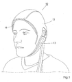
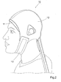
- a head cooler 10 comprises a thermal exchange cap 11 and an outer insulating cap 12, as shown in Fig 1 and 2 .
- the outer insulating cover is fitted over the thermal exchange cap to stabilize the cap on the patient.
- the outer cover is made of a heat insulating and elastic material, e.g. neoprenes of the type used in diving suits, to heat insulate the thermal exchange cap against the surroundings.
- a chinstrap 13 can improve the stabilization of the outer insulating cover.
- a first end of the strap is attached to the lower margin at one side of the outer cover and a second end of the strap, which is provided with a Velcro type fastener for adjustable and releasable connection, is attached at the other side of the outer cover.
- Figs 3 , 4 and 5 show the head cooler without the outer insulating cover.
- the thermal exchange cap 11 is made of a flexible and preferably elastic material, such as silicone rubber of medical grade, to fit tightly over the head and neck of a patient.
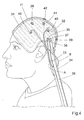
- the thermal exchange cap forms internal partitions, which can be made from the material of the cap and which define two channel systems, a first one 31 extending over the forward portion of the thermal exchange cap and a second one 32 extending over the neck portion of the thermal exchange cap.
- Flexible hoses 33 and 34 are connected to inlets 35 and 36 of the cap, communicating with the channel systems 31 and 32, respectively.
- An outlet 37, communicating with the both channel systems 31 and 32, is connected with a flexible hose 38.
- the hoses 33, 34, 38 are connected with an external device (not shown) for circulating a cooling fluid through the channel systems, and means are provided for controlling the flow of the cooling fluid. Since the front part of the head emits more heat than the back part of the head, the flow in the forward portion, i.e. in the first channel system 31, may be higher than in the neck portion, i.e. in the second channel system 32. Alternatively, the temperature of the cooling liquid may be lower in the forward portion than in the neck portion.
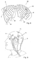
- the two channel systems 31 and 32 may be of a meander shape, a labyrinth shape, and/or maze shape, as disclosed in Figs. 3 to 6 . These shapes maximize the exchange surface against the head. It is also preferable to have the substantial extension of the channel systems 31 and 32 in the direction around the head, i.e. in a plane substantially perpendicular to the anteroposterior axis of the patient. In this way blood vessels in the head, having a substantial anterior direction, will be crossed by the flow of cooling liquid in an early phase of the cooling procedure, while the cooling ability of the cooling liquid still is high, assuring that substantially all the blood will be heat exchanged with the head cooler. Also, it is believed that the pressure to be applied may be minimized, since the cooling liquid only has to travel once from the inlet to the top of the head in a net anterior direction, i.e. upwards during use.
- the cooling liquid circulating in the head cooler will substantially move in a plane substantially perpendicular to the anteroposterior axis of the patient, while traveling from the posterior end to the anterior end of the head cooler by the stepwise elevation in the meander shaped, labyrinth shaped, and/or maze shaped channel systems 31 and 32.
- the warm blood to be cooled will be heat exchanged with cooling liquid of high cooling ability in a net parallel heat exchange, resulting in a more higher heat exchange effect posteriorly.
- a high heat exchange effect posteriorly is beneficial, since it then can be assured that the blood entering the scalp has an initial high temperature drop.
- the present invention may been realized by moulding the head cooler in two pieces of the flexible and preferably elastic material, such as silicone rubber of medical grade, wherein a first piece, for example the piece intended to be closest to the skull during use, may be moulded with the channel systems by forming ribs shaping the channel systems, while a second piece, for example the piece intended to be closest to the surroundings during use, may be a substantially flat piece. Thereafter, the first and second pieces are attached to each other by for example providing the ribs on the first piece with glue and then apply the second piece thereon, whereby the first piece and the second piece will be glued together while forming the channel systems 31 and 32 in space in between the ribs. It has up to this point not been possible to shape channel systems in head coolers in this way, whereby it has not been possible to manufacture head coolers with integrated meander shaped, labyrinth shaped, and/or maze shaped channel systems.
- a first piece for example the piece intended to be closest to the skull during use
- a second piece for example
- any other arrangement than that described herein can be provided for circulating the cooling fluid through the channel systems, for example the channel systems can have separate outlets, or the two channel systems can be interconnected, thus forming a single system having a single inlet.
- Alternate embodiments can comprise one system or more than two systems.
- the cross sections of the flow passages of the channel systems can be of any shape, e.g. circular, semi circular, elliptical, triangular, rectangular, square or wedge Shaped.
- the thermal exchange cap as shown in Figs 3 and 4 ,comprises two hollow studs 39 for insertion of temperature sensors for measuring the temperature on or close to the surface of the scalp in the regions of the channel systems 31 and 32, respectively.
- the sensors can be operatively connected with the device circulating cooling fluid through the channel systems for controlling the flow of cooling fluid and the temperature of the related region of the scalp in dependence of the temperature sensed.
- the cap comprises an additional hollow stud 41 for the insertion of a safety temperature sensor for measuring the temperature on or close to the surface of the scalp.
- the safety temperature sensor senses the temperature in an independent position on or close to the scalp, in relation to above mentioned stud(s) 39, and is operatively connected with the device for circulating cooling fluid, in order to shut off said device, e.g. if the temperature on or close to the scalp sinks below a set temperature to avoid frost injury.
- the studs may be omitted, or only one stud or more than two studs may be provided.
- a further hollow stud 42 to which an injection syringe 43 can be connected for the injection of a heat conducting material 44 into the gap, as illustrated in Fig 4 .
- Suitable materials for this purpose are e.g. gels, hydro gels, liquids, such as water or cooling liquid, and pastes.
- the material can include an additive, for example a blood vessel contracting substance, such as nicotine, and/or a heat conducting material, such as a salt or a metal.
- the stud 42 can be located in another position than that shown in Fig 4 , and additional hollow studs 40 can be provided in other positions on the cap, e.g. for inserting additional tubes A, B, which will be explained below.
- thermal exchange cap 60 is provided, as shown in Fig 6 .
- the thermal exchange cap 60 is partitioned into two sections 61 and 62, and has mutually overlapping edge portions sliding against each other. The edge portions may be oppositely bevelled in the transverse direction thereof to reduce the material thickness at the overlapping site.
- the cap has inlets 63 and 64, which are arranged to the sections 61 and 62, respectively, and are in communication with flow channels for circulating the cooling fluid through the flow channels, as described above.
- An outlet 65 is provided for recirculation of the cooling fluid back to the cooling device.
- a device 70 is arranged for interlocking the sections of the cap, taking into account different head sizes and also for the purpose of forming the smallest possible air gap between the inside surface of the thermal exchange cap and the patients head.
- a hole or an opening 71 is provided on the top of the cap, or at the point where the sections converge, to avoid a cone-shaped deformation of the cap.
- the flow passages from the inlet may be arranged along each defined side of the partitions of one or more sections, from the lower margin of the cap to the top of the cap, or further to the opposite lower margin, to avoid one or more gaps between the thermal exchange cap and the scalp at arrangement on the head of the patient.
- the flow passages may have a wedge shaped, a rectangular or a semi circular cross section having the base member or broadest member arranged against the head of the patient to improve the adaptation of the cap to the head.
- the thermal exchange cap may be partly partitioned into one section or fully partitioned into several sections, which converge to a point and extend into an opening.
- each section may have one or several inlets and one or several outlets, and may have multiple channel systems, which may be separated from each other or interconnected using or not using same inlet(s) and/or outlet(s).
- Supplementary holes may be provided on the inside and/or outside of the thermal exchange cap 11 and 60, which will be explained in detail below.
- the holes may be provided with valves or tubes.
- the thermal exchange cap may have elevated ridges (not shown) arranged on the exterior surface in order to form air gaps between the thermal exchange cap and the outer insulating cover 12, when arranged on the head of a patient.
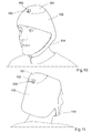
- an inner head cover 100 to be arranged on the patients head under the thermal exchange cap 11, 60, as a lining thereof.
- the inner head cover comprises a flattened bag made of one sheet, or two or several superposed sheets, of flexible elastic or not elastic plastic material or other material, which is/are welded, glued, stitched or in any other way joined forming one cavity or multiple separated cavities in the inner head cover.
- One or several holes 102, provided or not with valves 103, is/are arranged into the cavity or the multiple cavities to allow inlet of a circulating cooling fluid via tubes A, B, as shown in Fig 12 and 13 , from a cooling fluid source for filling up the cavity or cavities in order to minimize the air gap between the patients head and the thermal exchange cap 11, 60, and hence for improving the thermal conduction between the patients head and the thermal exchange cap.
- the holes 102 provided with or without valves or tubes A, B allow outlet of the cooling fluid for recirculation of the fluid back to the source.
- Figs 10 and 11 show the inner head cover 100 having a cavity 101 formed on the top thereof, wherein the cavity has at least two holes 102 provided with valves 103.
- tubes A, B may be arranged to the holes 102, as illustrated in Fig 12 and 13 .
- a chin strip 104 of plastic material is arranged to the lower margin of the inner head cover for securing the inner cover to the patient.
- the cavity (or cavities) of the inner head cover 100 communicates (communicate) with the channel systems of the thermal exchange cap 11, 60 by the holes 102, which are connected to the additional holes 40 of the thermal exchange cap 11, 60 via the valves 103, thus the channel systems of the cap supply the cooling fluid to the inner head cover.
- the supply can be performed continuously during the treatment, or instantly before start of the treatment. In the latter case the valves will be closed when the cavity/cavities is/are filled.
- the cavity is filled with cooling fluid via tubes A, B connected to at least one of the hoses 33, 34, 38, or by injecting the fluid by a syringe or another means.
- the cavity or cavities can be filled with a cooling fluid before placing the cover on the head of a patient.
- the valves 103 may be of different types, for example pressure regulating valves, non return valves, etc.
- One or several additional sealable or not sealable openings may be provided on the inner head cover for injection of a gel or other fluid having appropriate viscosity in order to minimize air gaps between the thermal exchange cap and the patient's head, for further improving the thermal conduction there between.
- a connection device for an emptying tube or emptying valve may be coupled to the hoses 34, 35, 38 mounted to the channel systems of the thermal exchange cap 11, 60, in order to inflate the cavity/cavities of the inner head cover by air or gas or a gas mixture of atmospheric pressure or overpressure, or deflate the cavity/cavities by vacuum, in order to evacuate the remaining cooling fluid of the cavity/cavities after finished treatment.
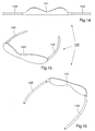
- the head cooler according to the embodiments described above can be complemented with an eyebrow cooler 140 for cooling the eyebrows of the patient, as shown in Figs 14, 15 and 16 .
- the eyebrow cooler is made of a flexible and preferably elastic material, such as silicone rubber or plastic material of medical grade, to be adapted closely to the forehead of a patient.
- the eyebrow cooler comprises a flattened bag made of one sheet, or two or several superposed sheets, which is/are welded, glued, stitched or in any other way joined forming one cavity or multiple cavities.
- Hoses 142 are connected to the eyebrow cooler at a first end, and are in communication with the cavity or cavities to allow inlet and outlet of a circulating cooling fluid.
- the second ends of the hoses 142 can be connected to the hoses 33 and 34, respectively, which are coupled to a cooling fluid source, or the ends can be coupled directly to the cooling source.
- the eyebrow cooler may comprise one or several hollow stud(s) (not shown) for the insertion of one or more temperature sensors for controlling the temperature at the area of the eyebrow cooler 140.
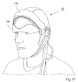
- the eyebrow cooler can be used in combination with the head cooler as shown in Figs 17 and 18 , or separately.
- Fig 17 shows a patient having an eyebrow cooler 140 arranged tightly over the eyebrows and a head cooler 10 arranged on the head.
- the hoses 142 are arranged under the outer insulating cover 12.
- An eyebrow cooler cover 170 is provided to be arranged over the eyebrow cooler 140 for insulation against the surrounding air, and is shown in a raised position in Fig 17 and in a lowered position in Fig 18 .
- Holes provided or not with valves, can be arranged into the cavity or the multiple cavities of the eyebrow cooler 140 for circulation and recirculation of the cooling fluid via external hoses in direct communication with the fluid source. Also, the eyebrow cooler can be filled with a cooling fluid before arranging it over the patient's eyebrows.
- the head cooler described above is provided for use in medicine, and more specifically for preventing hair loss during chemotherapy treatment.
- a method for preventing hair loss on a patient is also provided by arranging the head cooler on the head of said patient.
- the head cooler described above is provided for use in medicine, and more specifically for the treatment of patients suffered from stroke.
- the cooling of the head of stroke patients alleviates the damage caused by the stroke.
- a method for treatment of patients suffered from stroke is thus also provided by arranging the head cooler on the head of said patient.
Landscapes
- Health & Medical Sciences (AREA)
- Engineering & Computer Science (AREA)
- Biomedical Technology (AREA)
- Heart & Thoracic Surgery (AREA)
- Vascular Medicine (AREA)
- Life Sciences & Earth Sciences (AREA)
- Animal Behavior & Ethology (AREA)
- General Health & Medical Sciences (AREA)
- Public Health (AREA)
- Veterinary Medicine (AREA)
- Physics & Mathematics (AREA)
- Thermal Sciences (AREA)
- Thermotherapy And Cooling Therapy Devices (AREA)
- Cylinder Crankcases Of Internal Combustion Engines (AREA)
Abstract
Description
- The present invention relates to a head cooler to be arranged at the head of a person undergoing treatment of cytostatics.
- A human being undergoing treatment with cytostatics (chemotherapy) or similar treatment often suffers from loss of hair. By maintaining, during the treatment, a low temperature on/at/of the hairy region, usually the scalp, such a loss can be eliminated or substantially reduced.
- A head cooler disclosed in
US 6 156 059 comprises a head cover to be placed over a human scalp for enclosing the patient's head and neck. Flow passages, through which a cooling fluid is flown, are provided in the cover which forms an inside heat exchange surface to be applied against the scalp for cooling the scalp. A temperature sensor is mounted in connection with each flow passage for registering the local temperature. - The size and shape of heads of different patients may vary a lot. If the head cooler is too large or too wide, a gap may be formed between the heat exchange surface and the head. Then, the cooling of the scalp may be jeopardized, since the heat exchange surface is not held in contact with the scalp over the entire surface thereof. As a consequence the cooling efficiency will be reduced in the area of the gap resulting in loss of hair.
- It is proposed according to the Japanese Patent Abstract of Patent Application No.
6270060 - Another head cooling device is disclosed in
US 6,277,143 . - A drawback with currently used head coolers is that the head cover is not easily adaptable to the size and/or shape of the patient's head and neck, which may result in a too low or an impaired cooling efficiency.
- Another disadvantage is that the currently presented head coolers do not involve the cooling of the eyebrows or the region of the eyebrows. Loss of the eyebrows is also considered to be a problem for patients undergoing treatments with cytostatics.
- An object of the present invention is to eliminate or alleviate at least one of the drawbacks mentioned above, which is achieved by assigning to the device the characteristics according to
claim 1. - According to one aspect of the invention, there is provided a head cooler comprising a thermal exchange cap to be arranged on the head of a patient, and at least two flow passage systems for a cooling fluid provided in the thermal exchange cap forming an inside heat exchange surface to be applied against the head for cooling of the head. The thermal exchange cap is adaptable and/or adjustable to compensate for a discrepancy, if any, as to shape and size between the inside surface of the head cooler and the head.
- The head cooler further comprises an outer insulating cover made of a heat insulating material, e.g. also elastic, which encloses the thermal exchange cap. The head cooler comprises means for filling up, by the supply of a fluid heat conducting material, a gap between the inside surface of the thermal exchange cap and the head.
- According to one embodiment, the thermal exchange cap is partitioned into sections that are engageable at adjacent edge portions. The sections are mutually overlapping and are slidable against each other, and are oppositely bevelled in the transverse direction. Each section has at least one flow passage system for the cooling fluid. The cross sections of the flow passages are wedge shaped, circular, semi circular, rectangular, elliptical, square or of any other shape. The partitioned sections have a common inlet and/or outlet flow passage or a separate inlet and/or outlet flow passage for the cooling fluid. A flow passage extends along each side of the partitioned sections, which converge to a common location on the thermal exchange cap, preferably at the top, and extend into an opening on said location.
- The filling up means comprises at least one external connection on the thermal exchange cap communicating with a space between the inside of the thermal exchange cap and the scalp.
- According to another embodiment the head cooler further comprises an inner head cover consisting of a flattened bag of flexible material, which can be inflated, forming a lining on the inside of the thermal exchange cap. The bag forms a single cavity or multiple cavities. At least one valve or other means, such as a tube, is provided between a cavity of the bag and the flow passage system for supplying cooling fluid from said system to the bag cavity/cavities.
- Means are provided for controlling the flow of the cooling fluid. A connection is provided for supplying air or a gas or a gas mixture (under pressure) to the flow passage system or to the cavity or cavities to evacuate the cooling fluid from the bag.
- According to an alternative embodiment, the head cooler is complemented by an eyebrow cooler comprising a flattened bag of flexible material, which can be inflated. The bag forms a single cavity or multiple cavities, at least one valve or other means, such as a tube, is provided between the cavity of the bag and a flow passage system for supplying a cooling fluid from said system to the bag cavity/cavities.
- Further described is the use of a head cooler provided for preventing hair loss during chemotherapy treatment.
- Further objects, features and advantages of the present invention will appear from the following detailed description, from the attached drawings as well as from the dependent claims.
- In order to explain the invention, a number of embodiments of the invention will be described below with reference to the drawings, in which:
-
Fig 1 is a perspective view of a head cooler according to the invention, which is in use with a patient,Fig 2 is a side view of the head cooler inFig 1 , -
Fig 3 is a side view of the head cooler in use, but shown without the outer insulating cover, -
Fig 4 is the head cooler inFig 3 provided with additional tubes, -
Fig 5 is a side view of the head cooler inFig 4 during injection of a fluid filling up a gap between the heat exchange surface of the thermal exchange cap and the scalp, -
Fig 6 is a side view of a partitioned thermal exchange cap, wherein the sections are shown separated, -
Fig 7 is a side view of the cap inFig 6 with the sections closed and interconnected, -
Fig 8 shows the thermal exchange cap inFig 6 provided with additional tubes, -
Fig 9 shows the thermal exchange cap inFig 7 provided with additional tubes, -
Fig 10 is a frontal perspective view of an inner head cover having a cavity provided at the top thereof,Fig 11 is a perspective view of the inner head cover ofFig 10 from behind, -
Fig 12 shows the inner head cover inFig 10 provided with additional tubes, -
Fig 13 shows the inner head cover inFig 11 provided with additional tubes, -
Fig 14 is a frontal schematic view of an eyebrow cooler, -
Fig 15 is a perspective view of the eyebrow cooler inFig 14 , -
Fig 16 is a perspective view of the eyebrow cooler inFig 15 from behind, -
Fig 17 shows the head cooler inFig 1 provided with an eyebrow cooler and an insulating eyebrow cover in raised position, and -
Fig 18 shows the head cooler according toFig 17 with the insulating eyebrow cover in lowered position. - Same reference numerals have been used to indicate the same parts in the figures to increase the readability of the description and for the sake of clarity.
- A
head cooler 10 according to one embodiment of the invention comprises athermal exchange cap 11 and an outerinsulating cap 12, as shown inFig 1 and2 . The outer insulating cover is fitted over the thermal exchange cap to stabilize the cap on the patient. The outer cover is made of a heat insulating and elastic material, e.g. neoprenes of the type used in diving suits, to heat insulate the thermal exchange cap against the surroundings. - A
chinstrap 13 can improve the stabilization of the outer insulating cover. A first end of the strap is attached to the lower margin at one side of the outer cover and a second end of the strap, which is provided with a Velcro type fastener for adjustable and releasable connection, is attached at the other side of the outer cover. -
Figs 3 ,4 and5 show the head cooler without the outer insulating cover. Thethermal exchange cap 11 is made of a flexible and preferably elastic material, such as silicone rubber of medical grade, to fit tightly over the head and neck of a patient. The thermal exchange cap forms internal partitions, which can be made from the material of the cap and which define two channel systems, afirst one 31 extending over the forward portion of the thermal exchange cap and asecond one 32 extending over the neck portion of the thermal exchange cap.Flexible hoses inlets channel systems outlet 37, communicating with the bothchannel systems flexible hose 38. Thehoses first channel system 31, may be higher than in the neck portion, i.e. in thesecond channel system 32. Alternatively, the temperature of the cooling liquid may be lower in the forward portion than in the neck portion. - The two
channel systems Figs. 3 to 6 . These shapes maximize the exchange surface against the head. It is also preferable to have the substantial extension of thechannel systems - It is also preferable to have the
inlets Fig. 3 . Thus, the cooling liquid circulating in the head cooler will substantially move in a plane substantially perpendicular to the anteroposterior axis of the patient, while traveling from the posterior end to the anterior end of the head cooler by the stepwise elevation in the meander shaped, labyrinth shaped, and/or maze shapedchannel systems - The present invention may been realized by moulding the head cooler in two pieces of the flexible and preferably elastic material, such as silicone rubber of medical grade, wherein a first piece, for example the piece intended to be closest to the skull during use, may be moulded with the channel systems by forming ribs shaping the channel systems, while a second piece, for example the piece intended to be closest to the surroundings during use, may be a substantially flat piece. Thereafter, the first and second pieces are attached to each other by for example providing the ribs on the first piece with glue and then apply the second piece thereon, whereby the first piece and the second piece will be glued together while forming the
channel systems - Any other arrangement than that described herein can be provided for circulating the cooling fluid through the channel systems, for example the channel systems can have separate outlets, or the two channel systems can be interconnected, thus forming a single system having a single inlet. Alternate embodiments can comprise one system or more than two systems. The cross sections of the flow passages of the channel systems can be of any shape, e.g. circular, semi circular, elliptical, triangular, rectangular, square or wedge Shaped. The thermal exchange cap, as shown in
Figs 3 and4 ,comprises twohollow studs 39 for insertion of temperature sensors for measuring the temperature on or close to the surface of the scalp in the regions of thechannel systems - The cap comprises an additional
hollow stud 41 for the insertion of a safety temperature sensor for measuring the temperature on or close to the surface of the scalp. The safety temperature sensor senses the temperature in an independent position on or close to the scalp, in relation to above mentioned stud(s) 39, and is operatively connected with the device for circulating cooling fluid, in order to shut off said device, e.g. if the temperature on or close to the scalp sinks below a set temperature to avoid frost injury. - In an alternate embodiment the studs may be omitted, or only one stud or more than two studs may be provided.
- As explained above, there may be a discrepancy between the size and shape of the patient's head and neck and the size and shape of the thermal exchange cap, resulting in a gap between the inside of the heat exchange cap and the scalp. This may jeopardize the efficiency of the cooling of the patient's scalp, since the inside surface of the cap, i.e. the heat exchange surface, partially is not in contact with the surface of the scalp.
- In order to allow compensation for the discrepancy in shape, there can be provided, on the crown of the thermal exchange cap, a further
hollow stud 42 to which aninjection syringe 43 can be connected for the injection of aheat conducting material 44 into the gap, as illustrated inFig 4 . Suitable materials for this purpose are e.g. gels, hydro gels, liquids, such as water or cooling liquid, and pastes. The material can include an additive, for example a blood vessel contracting substance, such as nicotine, and/or a heat conducting material, such as a salt or a metal. Thestud 42 can be located in another position than that shown inFig 4 , and additionalhollow studs 40 can be provided in other positions on the cap, e.g. for inserting additional tubes A, B, which will be explained below. - To compensate for the discrepancy in size of head and neck, another embodiment of the
thermal exchange cap 60 is provided, as shown inFig 6 . Thethermal exchange cap 60 is partitioned into twosections inlets sections outlet 65 is provided for recirculation of the cooling fluid back to the cooling device. Adevice 70 is arranged for interlocking the sections of the cap, taking into account different head sizes and also for the purpose of forming the smallest possible air gap between the inside surface of the thermal exchange cap and the patients head. A hole or anopening 71, for example substantially circular or elliptical, is provided on the top of the cap, or at the point where the sections converge, to avoid a cone-shaped deformation of the cap. - To further improve the adaptation of the thermal exchange cap to the size of the head and neck of the patient, the flow passages from the inlet may be arranged along each defined side of the partitions of one or more sections, from the lower margin of the cap to the top of the cap, or further to the opposite lower margin, to avoid one or more gaps between the thermal exchange cap and the scalp at arrangement on the head of the patient. The flow passages may have a wedge shaped, a rectangular or a semi circular cross section having the base member or broadest member arranged against the head of the patient to improve the adaptation of the cap to the head.
- According to alternative embodiments, the thermal exchange cap may be partly partitioned into one section or fully partitioned into several sections, which converge to a point and extend into an opening. Furthermore, each section may have one or several inlets and one or several outlets, and may have multiple channel systems, which may be separated from each other or interconnected using or not using same inlet(s) and/or outlet(s).
- Supplementary holes, not shown, may be provided on the inside and/or outside of the
thermal exchange cap - The thermal exchange cap according to any of the described embodiments may have elevated ridges (not shown) arranged on the exterior surface in order to form air gaps between the thermal exchange cap and the outer insulating
cover 12, when arranged on the head of a patient. - To further improve the cooling efficiency of the head cooler, there is provided an
inner head cover 100 to be arranged on the patients head under thethermal exchange cap several holes 102, provided or not withvalves 103, is/are arranged into the cavity or the multiple cavities to allow inlet of a circulating cooling fluid via tubes A, B, as shown inFig 12 and 13 , from a cooling fluid source for filling up the cavity or cavities in order to minimize the air gap between the patients head and thethermal exchange cap holes 102 provided with or without valves or tubes A, B allow outlet of the cooling fluid for recirculation of the fluid back to the source. -
Figs 10 and 11 show theinner head cover 100 having acavity 101 formed on the top thereof, wherein the cavity has at least twoholes 102 provided withvalves 103. Alternatively, tubes A, B may be arranged to theholes 102, as illustrated inFig 12 and 13 . Achin strip 104 of plastic material is arranged to the lower margin of the inner head cover for securing the inner cover to the patient. - In a further embodiment the cavity (or cavities) of the
inner head cover 100 communicates (communicate) with the channel systems of thethermal exchange cap holes 102, which are connected to theadditional holes 40 of thethermal exchange cap valves 103, thus the channel systems of the cap supply the cooling fluid to the inner head cover. The supply can be performed continuously during the treatment, or instantly before start of the treatment. In the latter case the valves will be closed when the cavity/cavities is/are filled. Alternatively, the cavity is filled with cooling fluid via tubes A, B connected to at least one of thehoses valves 103 may be of different types, for example pressure regulating valves, non return valves, etc. - One or several additional sealable or not sealable openings may be provided on the inner head cover for injection of a gel or other fluid having appropriate viscosity in order to minimize air gaps between the thermal exchange cap and the patient's head, for further improving the thermal conduction there between.
- A connection device for an emptying tube or emptying valve may be coupled to the
hoses thermal exchange cap - In the embodiments described, there are several flow passages or channels in the thermal exchange cap for the cooling fluid, but it is also possible to have a single space or several spaces interconnected with each other, through which space/spaces the cooling fluid is passed between the fluid inlet and the fluid outlet.
- The head cooler according to the embodiments described above can be complemented with an eyebrow cooler 140 for cooling the eyebrows of the patient, as shown in
Figs 14, 15 and 16 . The eyebrow cooler is made of a flexible and preferably elastic material, such as silicone rubber or plastic material of medical grade, to be adapted closely to the forehead of a patient. The eyebrow cooler comprises a flattened bag made of one sheet, or two or several superposed sheets, which is/are welded, glued, stitched or in any other way joined forming one cavity or multiple cavities.Hoses 142 are connected to the eyebrow cooler at a first end, and are in communication with the cavity or cavities to allow inlet and outlet of a circulating cooling fluid. The second ends of thehoses 142 can be connected to thehoses eyebrow cooler 140. - The eyebrow cooler can be used in combination with the head cooler as shown in
Figs 17 and18 , or separately.Fig 17 shows a patient having an eyebrow cooler 140 arranged tightly over the eyebrows and a head cooler 10 arranged on the head. Thehoses 142 are arranged under the outer insulatingcover 12. An eyebrowcooler cover 170 is provided to be arranged over the eyebrow cooler 140 for insulation against the surrounding air, and is shown in a raised position inFig 17 and in a lowered position inFig 18 . - Holes, provided or not with valves, can be arranged into the cavity or the multiple cavities of the eyebrow cooler 140 for circulation and recirculation of the cooling fluid via external hoses in direct communication with the fluid source. Also, the eyebrow cooler can be filled with a cooling fluid before arranging it over the patient's eyebrows.
- The head cooler described above is provided for use in medicine, and more specifically for preventing hair loss during chemotherapy treatment. A method for preventing hair loss on a patient is also provided by arranging the head cooler on the head of said patient.
- Furthermore, the head cooler described above is provided for use in medicine, and more specifically for the treatment of patients suffered from stroke. The cooling of the head of stroke patients alleviates the damage caused by the stroke. A method for treatment of patients suffered from stroke is thus also provided by arranging the head cooler on the head of said patient.
- In the claims, the term "comprises/comprising" does not exclude the presence of other elements or steps. Furthermore, although individually listed, a plurality of means, elements or method steps may be implemented. Additionally, although individual features may be included in different embodiments, these may possibly be combined in other ways, and the inclusion in different embodiments does not imply that a combination of features is not feasible. In addition, singular references do not exclude a plurality. The terms "a", "an" does not preclude a plurality. Reference signs in the claims are provided merely as a clarifying example and shall not be construed as limiting the scope of the claims in any way.
Claims (11)
- A head cooler (10) comprising:a thermal exchange cap (11) to be arranged on the head of a patient,at least two channel systems (31, 32) for a cooling fluid provided in the thermal exchange cap (11) forming an inside heat exchange surface to be applied against the head for cooling of the head, andat least two inlets (35, 36) and at least one outlet (37) communicating with said at least two channel systems (31, 32), adapted to be connected to an external device for circulating a cooling fluid through said at least two channel systems (31, 32),
whereinthe thermal exchange cap (11) is adaptable and/or adjustable to compensate for a discrepancy, if any, as to shape and size between the inside surface of the head cooler (10) and the head, andwherein said at least two channel systems (31, 32) are meander shaped, labyrinth shaped, and/or maze shaped, andwherein each channels of the at least two channel systems is provided with its own inlet of the at least two inlets (35, 36) for independent provision of cooling fluid, and whereinsaid at least two channel systems (31, 32) comprise a first channel system and, a second channel system, said first channel system (31) extending over a forward portion of the thermal exchange cap (11) and said second channel system (32) extending over a neck portion of the thermal exchange cap (11), such that substantially the entire heat exchange surface is covered by said first channel system and said second channel system. - The head cooler according to claim 1, comprising an outlet (37), communicating with the first and second channel systems (31, 32).
- The head cooler (10) according to claim 1, further comprises an outer insulating cover (12) enclosing the thermal exchange cap (11).
- The head cooler (10) according to claim 1 or 3, further comprises a stud (42) for filling up, by the supply of a fluid heat conducting material, a gap between the inside surface of the thermal exchange cap and the head.
- The head cooler (10) according to claim 1, wherein the cross sections of flow passages of the channel systems are wedge shaped, circular, semi circular, rectangular, elliptical, square or of any other shape.
- The head cooler (10) of claim 3, wherein the outer insulating cover (12) is made of a heat insulating material.
- The head cooler (10) according to claim 1, further comprising an inner head cover (100) consisting of a flattened bag of flexible material forming a lining on the inside of the thermal exchange cap (11, 60), which bag can be inflated.
- The head cooler (10) according to claim 1, wherein a connection is provided for supplying air or a gas or a gas mixture (under pressure) to one or more of the channels of the channel systems or to the cavity or cavities to evacuate the in there contained cooling fluid.
- A head cooler according to claim 1, further comprises an eyebrow cooler (140) comprising a flattened bag of flexible material with a single or multiple cavities, which can be inflated.
- The head cooler (10) according to claim 9, wherein at least one valve or other means, such as a tube, is provided between the cavity/cavities of the bag and a flow passage system for supplying a cooling fluid from said system to the bag cavity/cavities.
- The head cooler according to claim 1, wherein the substantial extension of at least one of the channels of the at least two channel system (31, 32) is in a direction in a plane substantially perpendicular to the anteroposterior axis of the patient during use.
Applications Claiming Priority (2)
| Application Number | Priority Date | Filing Date | Title |
|---|---|---|---|
| SE0700374 | 2007-02-15 | ||
| PCT/EP2008/051890 WO2008099017A1 (en) | 2007-02-15 | 2008-02-15 | Head cooler |
Publications (2)
| Publication Number | Publication Date |
|---|---|
| EP2117484A1 EP2117484A1 (en) | 2009-11-18 |
| EP2117484B1 true EP2117484B1 (en) | 2011-03-30 |
Family
ID=39529747
Family Applications (1)
| Application Number | Title | Priority Date | Filing Date |
|---|---|---|---|
| EP20080709043 Active EP2117484B1 (en) | 2007-02-15 | 2008-02-15 | Head cooler |
Country Status (9)
| Country | Link |
|---|---|
| US (2) | US9101463B2 (en) |
| EP (1) | EP2117484B1 (en) |
| JP (1) | JP5133355B2 (en) |
| KR (1) | KR101477828B1 (en) |
| CN (1) | CN101631520B (en) |
| AT (1) | ATE503445T1 (en) |
| DE (1) | DE602008005853D1 (en) |
| ES (1) | ES2364102T3 (en) |
| WO (1) | WO2008099017A1 (en) |
Cited By (1)
| Publication number | Priority date | Publication date | Assignee | Title |
|---|---|---|---|---|
| US11141309B2 (en) | 2019-06-03 | 2021-10-12 | Cooler Heads Care, Inc. | Cooling cap assembly and cooling unit |
Families Citing this family (60)
| Publication number | Priority date | Publication date | Assignee | Title |
|---|---|---|---|---|
| US20050143797A1 (en) | 2003-07-18 | 2005-06-30 | Thermotek, Inc. | Compression sequenced thermal therapy system |
| US9119705B2 (en) | 1998-06-08 | 2015-09-01 | Thermotek, Inc. | Method and system for thermal and compression therapy relative to the prevention of deep vein thrombosis |
| US8574278B2 (en) | 2006-05-09 | 2013-11-05 | Thermotek, Inc. | Wound care method and system with one or both of vacuum-light therapy and thermally augmented oxygenation |
| US8128672B2 (en) | 2006-05-09 | 2012-03-06 | Thermotek, Inc. | Wound care method and system with one or both of vacuum-light therapy and thermally augmented oxygenation |
| US10016583B2 (en) | 2013-03-11 | 2018-07-10 | Thermotek, Inc. | Wound care and infusion method and system utilizing a thermally-treated therapeutic agent |
| US10765785B2 (en) | 2004-07-19 | 2020-09-08 | Thermotek, Inc. | Wound care and infusion method and system utilizing a therapeutic agent |
| CA2649875C (en) | 2006-04-20 | 2014-11-18 | University Of Pittsburgh | Method and apparatus of noninvasive, regional brain thermal stimuli for the treatment of neurological disorders |
| US11684510B2 (en) | 2006-04-20 | 2023-06-27 | University of Pittsburgh—of the Commonwealth System of Higher Education | Noninvasive, regional brain thermal stimuli for the treatment of neurological disorders |
| US8425583B2 (en) | 2006-04-20 | 2013-04-23 | University of Pittsburgh—of the Commonwealth System of Higher Education | Methods, devices and systems for treating insomnia by inducing frontal cerebral hypothermia |
| US9492313B2 (en) | 2006-04-20 | 2016-11-15 | University Of Pittsburgh - Of The Commonwealth System Of Higher Education | Method and apparatus of noninvasive, regional brain thermal stimuli for the treatment of neurological disorders |
| US12290640B2 (en) | 2006-04-20 | 2025-05-06 | University of Pittsburgh—of the Commonwealth System of Higher Education | Noninvasive, regional brain thermal stimulation for inducing relaxation |
| US9211212B2 (en) | 2006-04-20 | 2015-12-15 | Cerêve, Inc. | Apparatus and method for modulating sleep |
| WO2012006184A1 (en) * | 2010-06-29 | 2012-01-12 | Renato Rozental | Therapeutic brain cooling system and spinal cord cooling system |
| US20120245661A1 (en) * | 2011-03-24 | 2012-09-27 | Mason Jeffrey T | Cold Therapy Safety Switch |
| IES20110192A2 (en) * | 2011-04-18 | 2012-03-28 | Eurolec Instrumentation Ltd | Temperature regulation system |
| GB201111717D0 (en) * | 2011-07-08 | 2011-08-24 | Fronda Frank D | Headwear for removing heat from a persons scalp in order to prevent hair loss |
| US10512587B2 (en) | 2011-07-27 | 2019-12-24 | Thermotek, Inc. | Method and apparatus for scalp thermal treatment |
| WO2013162728A1 (en) | 2012-04-24 | 2013-10-31 | Thermotek, Inc. | Method and system for therapeutic use of ultra-violet light |
| ES2868181T3 (en) | 2013-01-02 | 2021-10-21 | Ebb Therapeutics Inc | Systems to improve sleep |
| DE102013010180A1 (en) * | 2013-01-07 | 2014-07-10 | W.E.T. Automotive Systems Ag | Treatment device for the therapeutic temperature control of body parts |
| US10300180B1 (en) | 2013-03-11 | 2019-05-28 | Thermotek, Inc. | Wound care and infusion method and system utilizing a therapeutic agent |
| US20140379058A1 (en) * | 2013-06-24 | 2014-12-25 | Ampac Enterprises Inc. | Apparatus and Method for Cooling Head Injury |
| JP2015008958A (en) * | 2013-06-28 | 2015-01-19 | 下田 一喜 | Medical human body temperature controller |
| EP3068481B1 (en) | 2013-11-11 | 2020-01-01 | Thermotek, Inc. | System for wound care |
| EP2878287A1 (en) * | 2013-12-02 | 2015-06-03 | Beheer B.V. Arline | Device for cooling scalp |
| JP6189229B2 (en) * | 2014-02-24 | 2017-08-30 | 株式会社毛髪クリニックリーブ21 | Inner cap and scalp cooling device including the same |
| JP6189228B2 (en) * | 2014-02-24 | 2017-08-30 | 株式会社毛髪クリニックリーブ21 | Scalp cooling device |
| GB2527378B (en) | 2014-09-23 | 2017-03-29 | Paxman Coolers Ltd | Temperature control system |
| GB2528512B (en) | 2014-09-23 | 2016-12-07 | Paxman Coolers Ltd | Heat exchanger cap |
| GB2530496B (en) * | 2014-09-23 | 2017-04-05 | Paxman Coolers Ltd | Heat exchanger |
| US10806626B2 (en) | 2015-02-04 | 2020-10-20 | Michael Lynn Zumbrunnen | Method and apparatus of a self-managed portable hypothermia system |
| US10478637B2 (en) * | 2015-04-30 | 2019-11-19 | Hair Science Systems Llc | System and method for limiting chemotherapy-induced alopecia |
| KR101645592B1 (en) | 2016-02-24 | 2016-08-12 | 박제규 | Mesh Type Scalp Cooling Cap |
| CN105963068A (en) * | 2016-06-29 | 2016-09-28 | 惠州市哈罗德科技有限公司 | Slot type cooling structure |
| CN105997337A (en) * | 2016-06-29 | 2016-10-12 | 惠州市哈罗德科技有限公司 | Cool storage structure |
| CN105963066A (en) * | 2016-06-29 | 2016-09-28 | 惠州市哈罗德科技有限公司 | Temperature sensing device |
| US20210307439A1 (en) * | 2016-11-17 | 2021-10-07 | Hair Clinic Reve-21 Corporation | Easy-Fitting Coif for Scalp-Cooling Cap |
| AU2018211029A1 (en) * | 2017-01-17 | 2019-08-01 | Corfigo, Inc. | Device for ablation of tissue surfaces and related systems and methods |
| US20180199879A1 (en) * | 2017-01-17 | 2018-07-19 | Peter Kanistros | System and method to control temperature |
| CN108451701A (en) * | 2017-02-22 | 2018-08-28 | 青岛瑞思德生物科技有限公司 | The temperature automatically controlled cold compress device of testis |
| KR101983024B1 (en) * | 2018-03-12 | 2019-05-28 | 인천대학교 산학협력단 | Cooling water pockets for fire fighting |
| US10470922B1 (en) | 2018-05-14 | 2019-11-12 | Mark Louis Venturi | Blood flow restricting headwear |
| CN108936939A (en) * | 2018-07-30 | 2018-12-07 | 安徽省旌德飞迅安全设备有限公司 | A kind of dust-proof intercommunication type intelligent safety helmet |
| EP3876881A4 (en) | 2018-11-09 | 2022-08-03 | Dignitana AB | SCALP COOLING APPARATUS, METHOD AND SYSTEM |
| IT201800010255A1 (en) * | 2018-11-15 | 2020-05-15 | Gian Vittorio Pizzi | SYSTEM FOR THERAPEUTIC HYPOTHERMAL AND HEATING FOR THERMOGENESIS NOT THRILLING |
| US11850183B2 (en) | 2019-08-20 | 2023-12-26 | Michael L. Wilford | Head wrap |
| USD888968S1 (en) * | 2019-10-12 | 2020-06-30 | 911 Medical Devices | Head wrap |
| CN110946693B (en) * | 2019-12-26 | 2024-11-26 | 宁波艾思吉制冷设备有限公司 | Low temperature cooling headgear |
| JP7043532B2 (en) * | 2020-02-28 | 2022-03-29 | 株式会社毛髪クリニックリーブ21 | Medical head cooling cap set |
| EP4681697A3 (en) * | 2020-06-24 | 2026-04-01 | Guangzhou Follisave Technology Development Ltd. | Vasocompression devices and methods of delivering vasocompression therapy to a patient undergoing chemotherapy treatment |
| JP7902174B2 (en) * | 2020-10-27 | 2026-08-07 | ユニバーシティー オブ ゴールウェイ | Air compression therapy device |
| US12622806B2 (en) * | 2020-11-05 | 2026-05-12 | National University Hospital (Singapore) Pte Ltd | Wearable limb wraps for temperature-controlled therapy |
| CN112603639B (en) * | 2020-12-30 | 2022-07-19 | 吉林大学第一医院 | Temperature control device for cardiac surgery nursing |
| US20230010829A1 (en) * | 2021-07-08 | 2023-01-12 | Vikram Singh Bhinder | Patient targeted temperature management device and method |
| CN116672617B (en) * | 2023-08-04 | 2024-01-02 | 慧创科仪(北京)科技有限公司 | Brain optical treatment device and optical treatment equipment |
| USD1089667S1 (en) | 2023-11-30 | 2025-08-19 | Michael L. Wilford | Lumbar wrap |
| USD1089666S1 (en) | 2023-11-30 | 2025-08-19 | Michael L. Wilford | Cervical wrap |
| USD1089665S1 (en) | 2023-11-30 | 2025-08-19 | Michael L. Wilford | Shoulder wrap |
| TWI918054B (en) | 2024-08-04 | 2026-03-11 | 瑪旺幹細胞醫學生物科技股份有限公司 | Scalp cooling device |
| KR102780289B1 (en) * | 2024-08-20 | 2025-03-12 | 주식회사 써지쿨 | Apparatus for control body temperature |
Family Cites Families (34)
| Publication number | Priority date | Publication date | Assignee | Title |
|---|---|---|---|---|
| US3027894A (en) * | 1958-05-28 | 1962-04-03 | Florida Mfg Corp | All purpose cervical collar |
| US4138743A (en) * | 1975-02-25 | 1979-02-13 | Acurex Corporation | Liquid cooled helmet |
| US4172495A (en) * | 1977-08-03 | 1979-10-30 | Energy Systems Corporation | Slurry cooling of helmets |
| AU8412082A (en) * | 1981-05-25 | 1982-12-02 | Jones, P.B. | Scalp temperature regulator cap |
| EP0076080A3 (en) * | 1981-09-25 | 1983-08-10 | The Secretary of State for Defence in Her Britannic Majesty's Government of the United Kingdom of Great Britain and | Apparatus for cooling a scalp |
| JPS6013118U (en) * | 1983-04-18 | 1985-01-29 | 日石三菱株式会社 | Head cooling device to prevent hair loss due to side effects of anticancer drugs |
| JPH0115385Y2 (en) * | 1985-05-27 | 1989-05-09 | ||
| US5228431A (en) * | 1990-04-26 | 1993-07-20 | Giarretto Ralph R | Drug-free method for treatment of the scalp for therapeutic purposes |
| US6277143B1 (en) | 1991-05-22 | 2001-08-21 | Life Science Holdings, Inc. | Brain cooling apparatus and method for cooling the brain |
| WO1994000087A1 (en) * | 1992-06-22 | 1994-01-06 | Ergomed, Inc. | Versatile therapeutic cold pack |
| JPH06270060A (en) | 1993-03-24 | 1994-09-27 | Shin Meiwa Ind Co Ltd | Grinding reference plane position detecting device for grinding robot |
| JPH0860423A (en) * | 1994-08-18 | 1996-03-05 | Yasutoshi Kurosawa | Head cooling device |
| JP2802597B2 (en) * | 1994-12-12 | 1998-09-24 | 享 宮池 | Medical head cooling device |
| JPH09228135A (en) * | 1996-02-29 | 1997-09-02 | Norihiko Yamamoto | Helmet cover to prevent sunstroke |
| SE506911C2 (en) | 1996-10-17 | 1998-03-02 | Yvonne Olofsson | Device for controlled scalp tempering |
| US6126680A (en) * | 1997-04-03 | 2000-10-03 | Mayo Foundation For Medical Education And Research | Selective convective brain cooling apparatus and method |
| AU8778398A (en) * | 1997-08-13 | 1999-03-08 | Life Science Holdings, Inc. | Brain cooling apparatus and method for cooling the brain |
| US6312453B1 (en) | 1998-07-16 | 2001-11-06 | Olympic Medical Corp. | Device for cooling infant's brain |
| US6183501B1 (en) | 1998-12-18 | 2001-02-06 | Jeffrey W. Latham | Head and spine cooling device |
| US6178562B1 (en) * | 2000-01-28 | 2001-01-30 | Coolsystems, Inc | Cap and vest garment components of an animate body heat exchanger |
| US20020058976A1 (en) | 2000-11-15 | 2002-05-16 | Carole Lee | Temperature indicating chemotherapy cap |
| JP2002272775A (en) * | 2001-03-19 | 2002-09-24 | Fujikura Rubber Ltd | Cooling headgear and method of manufacturing the same |
| JP2005504063A (en) * | 2001-09-03 | 2005-02-10 | リシャール・ヴェルミー | Compositions and methods related to prevention of chemotherapy-induced hair loss |
| US7156867B2 (en) * | 2001-12-31 | 2007-01-02 | Medcool, Inc. | Uniform selective cerebral hypothermia |
| US7052509B2 (en) * | 2002-04-29 | 2006-05-30 | Medcool, Inc. | Method and device for rapidly inducing and then maintaining hypothermia |
| US7666213B2 (en) * | 2002-07-11 | 2010-02-23 | Life Recovery Systems Hd, Llc | Apparatus for altering the body temperature of a patient |
| US20040249427A1 (en) * | 2003-06-06 | 2004-12-09 | Yunes Nabilsi | Medical cooler device |
| JP3616777B1 (en) * | 2003-07-24 | 2005-02-02 | 宝養生資材株式会社 | Cooling helmet |
| US6962600B2 (en) * | 2003-08-04 | 2005-11-08 | Medcool, Inc. | Method and apparatus for reducing body temperature of a subject |
| US20080038455A1 (en) * | 2004-07-07 | 2008-02-14 | Nne, Inc. | Multilayer Optical Disc and Method and Apparatus For Making Same |
| GB2418614B (en) * | 2004-07-28 | 2009-02-11 | Nicholas James Rose | Application pack for cryotherapy |
| CN2855382Y (en) * | 2005-10-11 | 2007-01-10 | 鲍建洲 | Medical craniocerebral temp lowering instrument |
| US8529613B2 (en) * | 2006-10-18 | 2013-09-10 | Medcool, Inc. | Adjustable thermal cap |
| US8166772B2 (en) * | 2008-02-08 | 2012-05-01 | Yupoong, Inc. | Flexile plated cooling pack of headwear and method for making the same |
-
2008
- 2008-02-15 WO PCT/EP2008/051890 patent/WO2008099017A1/en not_active Ceased
- 2008-02-15 ES ES08709043T patent/ES2364102T3/en active Active
- 2008-02-15 KR KR1020097018500A patent/KR101477828B1/en active Active
- 2008-02-15 DE DE200860005853 patent/DE602008005853D1/en active Active
- 2008-02-15 JP JP2009549426A patent/JP5133355B2/en active Active
- 2008-02-15 EP EP20080709043 patent/EP2117484B1/en active Active
- 2008-02-15 CN CN2008800053035A patent/CN101631520B/en active Active
- 2008-02-15 US US12/525,744 patent/US9101463B2/en active Active
- 2008-02-15 AT AT08709043T patent/ATE503445T1/en not_active IP Right Cessation
-
2011
- 2011-10-19 US US13/276,912 patent/US9421125B2/en active Active
Cited By (3)
| Publication number | Priority date | Publication date | Assignee | Title |
|---|---|---|---|---|
| US11141309B2 (en) | 2019-06-03 | 2021-10-12 | Cooler Heads Care, Inc. | Cooling cap assembly and cooling unit |
| US11622881B2 (en) | 2019-06-03 | 2023-04-11 | Cooler Heads Care, Inc. | Cooling cap assembly and cooling unit |
| US12702585B2 (en) | 2019-06-03 | 2026-08-11 | Cooler Heads Care, Inc. | Cooling cap assembly and cooling unit |
Also Published As
| Publication number | Publication date |
|---|---|
| EP2117484A1 (en) | 2009-11-18 |
| KR101477828B1 (en) | 2014-12-30 |
| CN101631520B (en) | 2011-07-06 |
| US20100186436A1 (en) | 2010-07-29 |
| ATE503445T1 (en) | 2011-04-15 |
| CN101631520A (en) | 2010-01-20 |
| JP5133355B2 (en) | 2013-01-30 |
| ES2364102T3 (en) | 2011-08-24 |
| US9101463B2 (en) | 2015-08-11 |
| JP2010517717A (en) | 2010-05-27 |
| US9421125B2 (en) | 2016-08-23 |
| WO2008099017A1 (en) | 2008-08-21 |
| US20120041526A1 (en) | 2012-02-16 |
| DE602008005853D1 (en) | 2011-05-12 |
| KR20090110369A (en) | 2009-10-21 |
Similar Documents
| Publication | Publication Date | Title |
|---|---|---|
| US9101463B2 (en) | Head cooler | |
| US8696726B2 (en) | Flexible closed flat pad for cooling a body part | |
| US8529613B2 (en) | Adjustable thermal cap | |
| JP6059172B2 (en) | Devices, systems, and methods for removing heat from fat-rich subcutaneous cells | |
| US10478637B2 (en) | System and method for limiting chemotherapy-induced alopecia | |
| US8894698B2 (en) | Thermal therapy body wraps | |
| US10342696B2 (en) | Portable rapid cooling, hypothermia inducing headgear apparatus for tissue preservation | |
| US20050065581A1 (en) | Flexible heat exchangers for medical cooling and warming applications | |
| US11311364B2 (en) | Hand-held therapeutic oral device for cooling oral tissue of a user | |
| JP2004524938A (en) | Local body cooling / heating apparatus and method | |
| US8961443B2 (en) | Inflatable cervical traction device | |
| US11357664B2 (en) | Hand-held mouthpiece for cooling of oral tissue of a user | |
| US11957618B2 (en) | Cooling pad | |
| US8900170B1 (en) | Temperature control headliner | |
| CN215994462U (en) | Medical anti-hair loss device | |
| US6500199B1 (en) | Enclosure bag for maintaining a patient's body temperature during surgical procedures | |
| ES2938763T3 (en) | System for controlling the temperature of a person's head | |
| CN219847048U (en) | A kind of medical ice cap | |
| CN212699427U (en) | Head decompression pillow for neurosurgery | |
| US20060111764A1 (en) | Medical device having a dual fluid circulation structure for thermally affecting tissue | |
| CN213525805U (en) | Rapid cooling device is used in nursing of general branch of academic or vocational study | |
| US20130317577A1 (en) | Therapeutic cooling device | |
| CN211863061U (en) | Neck support for fixing neck | |
| CA3089106A1 (en) | Mouth piece for cooling of oral tissue | |
| JPH08275854A (en) | Ice pillow with neck cooling function |
Legal Events
| Date | Code | Title | Description |
|---|---|---|---|
| PUAI | Public reference made under article 153(3) epc to a published international application that has entered the european phase |
Free format text: ORIGINAL CODE: 0009012 |
|
| 17P | Request for examination filed |
Effective date: 20090902 |
|
| AK | Designated contracting states |
Kind code of ref document: A1 Designated state(s): AT BE BG CH CY CZ DE DK EE ES FI FR GB GR HR HU IE IS IT LI LT LU LV MC MT NL NO PL PT RO SE SI SK TR |
|
| RIN1 | Information on inventor provided before grant (corrected) |
Inventor name: STORMBY, JOHAN |
|
| DAX | Request for extension of the european patent (deleted) | ||
| 17Q | First examination report despatched |
Effective date: 20100512 |
|
| GRAP | Despatch of communication of intention to grant a patent |
Free format text: ORIGINAL CODE: EPIDOSNIGR1 |
|
| RIC1 | Information provided on ipc code assigned before grant |
Ipc: A61F 7/10 20060101AFI20100910BHEP |
|
| GRAS | Grant fee paid |
Free format text: ORIGINAL CODE: EPIDOSNIGR3 |
|
| GRAA | (expected) grant |
Free format text: ORIGINAL CODE: 0009210 |
|
| AK | Designated contracting states |
Kind code of ref document: B1 Designated state(s): AT BE BG CH CY CZ DE DK EE ES FI FR GB GR HR HU IE IS IT LI LT LU LV MC MT NL NO PL PT RO SE SI SK TR |
|
| REG | Reference to a national code |
Ref country code: GB Ref legal event code: FG4D |
|
| REG | Reference to a national code |
Ref country code: CH Ref legal event code: EP |
|
| REG | Reference to a national code |
Ref country code: IE Ref legal event code: FG4D |
|
| REF | Corresponds to: |
Ref document number: 602008005853 Country of ref document: DE Date of ref document: 20110512 Kind code of ref document: P |
|
| REG | Reference to a national code |
Ref country code: DE Ref legal event code: R096 Ref document number: 602008005853 Country of ref document: DE Effective date: 20110512 |
|
| REG | Reference to a national code |
Ref country code: NL Ref legal event code: VDEP Effective date: 20110330 |
|
| REG | Reference to a national code |
Ref country code: SE Ref legal event code: TRGR |
|
| PG25 | Lapsed in a contracting state [announced via postgrant information from national office to epo] |
Ref country code: GR Free format text: LAPSE BECAUSE OF FAILURE TO SUBMIT A TRANSLATION OF THE DESCRIPTION OR TO PAY THE FEE WITHIN THE PRESCRIBED TIME-LIMIT Effective date: 20110701 Ref country code: HR Free format text: LAPSE BECAUSE OF FAILURE TO SUBMIT A TRANSLATION OF THE DESCRIPTION OR TO PAY THE FEE WITHIN THE PRESCRIBED TIME-LIMIT Effective date: 20110330 Ref country code: LV Free format text: LAPSE BECAUSE OF FAILURE TO SUBMIT A TRANSLATION OF THE DESCRIPTION OR TO PAY THE FEE WITHIN THE PRESCRIBED TIME-LIMIT Effective date: 20110330 Ref country code: LT Free format text: LAPSE BECAUSE OF FAILURE TO SUBMIT A TRANSLATION OF THE DESCRIPTION OR TO PAY THE FEE WITHIN THE PRESCRIBED TIME-LIMIT Effective date: 20110330 |
|
| REG | Reference to a national code |
Ref country code: ES Ref legal event code: FG2A Ref document number: 2364102 Country of ref document: ES Kind code of ref document: T3 Effective date: 20110824 |
|
| LTIE | Lt: invalidation of european patent or patent extension |
Effective date: 20110330 |
|
| PG25 | Lapsed in a contracting state [announced via postgrant information from national office to epo] |
Ref country code: AT Free format text: LAPSE BECAUSE OF FAILURE TO SUBMIT A TRANSLATION OF THE DESCRIPTION OR TO PAY THE FEE WITHIN THE PRESCRIBED TIME-LIMIT Effective date: 20110330 Ref country code: CY Free format text: LAPSE BECAUSE OF FAILURE TO SUBMIT A TRANSLATION OF THE DESCRIPTION OR TO PAY THE FEE WITHIN THE PRESCRIBED TIME-LIMIT Effective date: 20110330 Ref country code: SI Free format text: LAPSE BECAUSE OF FAILURE TO SUBMIT A TRANSLATION OF THE DESCRIPTION OR TO PAY THE FEE WITHIN THE PRESCRIBED TIME-LIMIT Effective date: 20110330 Ref country code: NO Free format text: LAPSE BECAUSE OF FAILURE TO SUBMIT A TRANSLATION OF THE DESCRIPTION OR TO PAY THE FEE WITHIN THE PRESCRIBED TIME-LIMIT Effective date: 20110630 Ref country code: FI Free format text: LAPSE BECAUSE OF FAILURE TO SUBMIT A TRANSLATION OF THE DESCRIPTION OR TO PAY THE FEE WITHIN THE PRESCRIBED TIME-LIMIT Effective date: 20110330 |
|
| REG | Reference to a national code |
Ref country code: DE Ref legal event code: R082 Ref document number: 602008005853 Country of ref document: DE Representative=s name: HAFNER & PARTNER PATENT-/ RECHTSANWALTSKANZLEI, DE Ref country code: DE Ref legal event code: R082 Ref document number: 602008005853 Country of ref document: DE Representative=s name: HAFNER & PARTNER, DE Ref country code: DE Ref legal event code: R082 Ref document number: 602008005853 Country of ref document: DE Representative=s name: HAFNER & KOHL, DE Ref country code: DE Ref legal event code: R082 Ref document number: 602008005853 Country of ref document: DE Representative=s name: HAFNER & KOHL PARTMBB, DE Ref country code: DE Ref legal event code: R082 Ref document number: 602008005853 Country of ref document: DE Representative=s name: HAFNER & KOHL PATENTANWALTSKANZLEI RECHTSANWAL, DE |
|
| PG25 | Lapsed in a contracting state [announced via postgrant information from national office to epo] |
Ref country code: BE Free format text: LAPSE BECAUSE OF FAILURE TO SUBMIT A TRANSLATION OF THE DESCRIPTION OR TO PAY THE FEE WITHIN THE PRESCRIBED TIME-LIMIT Effective date: 20110330 |
|
| PG25 | Lapsed in a contracting state [announced via postgrant information from national office to epo] |
Ref country code: EE Free format text: LAPSE BECAUSE OF FAILURE TO SUBMIT A TRANSLATION OF THE DESCRIPTION OR TO PAY THE FEE WITHIN THE PRESCRIBED TIME-LIMIT Effective date: 20110330 Ref country code: PT Free format text: LAPSE BECAUSE OF FAILURE TO SUBMIT A TRANSLATION OF THE DESCRIPTION OR TO PAY THE FEE WITHIN THE PRESCRIBED TIME-LIMIT Effective date: 20110801 |
|
| PG25 | Lapsed in a contracting state [announced via postgrant information from national office to epo] |
Ref country code: IS Free format text: LAPSE BECAUSE OF FAILURE TO SUBMIT A TRANSLATION OF THE DESCRIPTION OR TO PAY THE FEE WITHIN THE PRESCRIBED TIME-LIMIT Effective date: 20110730 Ref country code: CZ Free format text: LAPSE BECAUSE OF FAILURE TO SUBMIT A TRANSLATION OF THE DESCRIPTION OR TO PAY THE FEE WITHIN THE PRESCRIBED TIME-LIMIT Effective date: 20110330 Ref country code: SK Free format text: LAPSE BECAUSE OF FAILURE TO SUBMIT A TRANSLATION OF THE DESCRIPTION OR TO PAY THE FEE WITHIN THE PRESCRIBED TIME-LIMIT Effective date: 20110330 Ref country code: RO Free format text: LAPSE BECAUSE OF FAILURE TO SUBMIT A TRANSLATION OF THE DESCRIPTION OR TO PAY THE FEE WITHIN THE PRESCRIBED TIME-LIMIT Effective date: 20110330 |
|
| PG25 | Lapsed in a contracting state [announced via postgrant information from national office to epo] |
Ref country code: NL Free format text: LAPSE BECAUSE OF FAILURE TO SUBMIT A TRANSLATION OF THE DESCRIPTION OR TO PAY THE FEE WITHIN THE PRESCRIBED TIME-LIMIT Effective date: 20110330 |
|
| PLBE | No opposition filed within time limit |
Free format text: ORIGINAL CODE: 0009261 |
|
| STAA | Information on the status of an ep patent application or granted ep patent |
Free format text: STATUS: NO OPPOSITION FILED WITHIN TIME LIMIT |
|
| PG25 | Lapsed in a contracting state [announced via postgrant information from national office to epo] |
Ref country code: PL Free format text: LAPSE BECAUSE OF FAILURE TO SUBMIT A TRANSLATION OF THE DESCRIPTION OR TO PAY THE FEE WITHIN THE PRESCRIBED TIME-LIMIT Effective date: 20110330 Ref country code: DK Free format text: LAPSE BECAUSE OF FAILURE TO SUBMIT A TRANSLATION OF THE DESCRIPTION OR TO PAY THE FEE WITHIN THE PRESCRIBED TIME-LIMIT Effective date: 20110330 |
|
| 26N | No opposition filed |
Effective date: 20120102 |
|
| REG | Reference to a national code |
Ref country code: DE Ref legal event code: R097 Ref document number: 602008005853 Country of ref document: DE Effective date: 20120102 |
|
| PG25 | Lapsed in a contracting state [announced via postgrant information from national office to epo] |
Ref country code: MC Free format text: LAPSE BECAUSE OF NON-PAYMENT OF DUE FEES Effective date: 20120229 |
|
| REG | Reference to a national code |
Ref country code: CH Ref legal event code: PL |
|
| PG25 | Lapsed in a contracting state [announced via postgrant information from national office to epo] |
Ref country code: LI Free format text: LAPSE BECAUSE OF NON-PAYMENT OF DUE FEES Effective date: 20120229 Ref country code: CH Free format text: LAPSE BECAUSE OF NON-PAYMENT OF DUE FEES Effective date: 20120229 |
|
| REG | Reference to a national code |
Ref country code: IE Ref legal event code: MM4A |
|
| PG25 | Lapsed in a contracting state [announced via postgrant information from national office to epo] |
Ref country code: IE Free format text: LAPSE BECAUSE OF NON-PAYMENT OF DUE FEES Effective date: 20120215 |
|
| PG25 | Lapsed in a contracting state [announced via postgrant information from national office to epo] |
Ref country code: BG Free format text: LAPSE BECAUSE OF FAILURE TO SUBMIT A TRANSLATION OF THE DESCRIPTION OR TO PAY THE FEE WITHIN THE PRESCRIBED TIME-LIMIT Effective date: 20110630 |
|
| PG25 | Lapsed in a contracting state [announced via postgrant information from national office to epo] |
Ref country code: MT Free format text: LAPSE BECAUSE OF FAILURE TO SUBMIT A TRANSLATION OF THE DESCRIPTION OR TO PAY THE FEE WITHIN THE PRESCRIBED TIME-LIMIT Effective date: 20110330 |
|
| PG25 | Lapsed in a contracting state [announced via postgrant information from national office to epo] |
Ref country code: TR Free format text: LAPSE BECAUSE OF FAILURE TO SUBMIT A TRANSLATION OF THE DESCRIPTION OR TO PAY THE FEE WITHIN THE PRESCRIBED TIME-LIMIT Effective date: 20110330 |
|
| PG25 | Lapsed in a contracting state [announced via postgrant information from national office to epo] |
Ref country code: LU Free format text: LAPSE BECAUSE OF NON-PAYMENT OF DUE FEES Effective date: 20120215 |
|
| PG25 | Lapsed in a contracting state [announced via postgrant information from national office to epo] |
Ref country code: HU Free format text: LAPSE BECAUSE OF FAILURE TO SUBMIT A TRANSLATION OF THE DESCRIPTION OR TO PAY THE FEE WITHIN THE PRESCRIBED TIME-LIMIT Effective date: 20080215 |
|
| REG | Reference to a national code |
Ref country code: FR Ref legal event code: PLFP Year of fee payment: 9 |
|
| REG | Reference to a national code |
Ref country code: FR Ref legal event code: PLFP Year of fee payment: 10 |
|
| REG | Reference to a national code |
Ref country code: FR Ref legal event code: PLFP Year of fee payment: 11 |
|
| PGFP | Annual fee paid to national office [announced via postgrant information from national office to epo] |
Ref country code: DE Payment date: 20250220 Year of fee payment: 18 |
|
| PGFP | Annual fee paid to national office [announced via postgrant information from national office to epo] |
Ref country code: ES Payment date: 20250307 Year of fee payment: 18 |
|
| PGFP | Annual fee paid to national office [announced via postgrant information from national office to epo] |
Ref country code: SE Payment date: 20250219 Year of fee payment: 18 |
|
| PGFP | Annual fee paid to national office [announced via postgrant information from national office to epo] |
Ref country code: FR Payment date: 20250218 Year of fee payment: 18 |
|
| PGFP | Annual fee paid to national office [announced via postgrant information from national office to epo] |
Ref country code: IT Payment date: 20250129 Year of fee payment: 18 Ref country code: GB Payment date: 20250218 Year of fee payment: 18 |