EP2117325B1 - Kette zum formen von würsten oder dergleichen und maschine mit derartiger kette - Google Patents
Kette zum formen von würsten oder dergleichen und maschine mit derartiger kette Download PDFInfo
- Publication number
- EP2117325B1 EP2117325B1 EP08707403A EP08707403A EP2117325B1 EP 2117325 B1 EP2117325 B1 EP 2117325B1 EP 08707403 A EP08707403 A EP 08707403A EP 08707403 A EP08707403 A EP 08707403A EP 2117325 B1 EP2117325 B1 EP 2117325B1
- Authority
- EP
- European Patent Office
- Prior art keywords
- chain
- link
- pinching
- chain according
- elements
- Prior art date
- Legal status (The legal status is an assumption and is not a legal conclusion. Google has not performed a legal analysis and makes no representation as to the accuracy of the status listed.)
- Not-in-force
Links
- 235000013580 sausages Nutrition 0.000 title claims abstract description 50
- 235000013372 meat Nutrition 0.000 claims abstract description 28
- 229920003023 plastic Polymers 0.000 claims description 2
- 239000004033 plastic Substances 0.000 claims description 2
- 239000002184 metal Substances 0.000 description 3
- 238000004873 anchoring Methods 0.000 description 2
- 229920004943 Delrin® Polymers 0.000 description 1
- 229910000831 Steel Inorganic materials 0.000 description 1
- 238000004140 cleaning Methods 0.000 description 1
- 238000004519 manufacturing process Methods 0.000 description 1
- 238000000034 method Methods 0.000 description 1
- 239000010959 steel Substances 0.000 description 1
Images


Classifications
-
- H—ELECTRICITY
- H02—GENERATION; CONVERSION OR DISTRIBUTION OF ELECTRIC POWER
- H02G—INSTALLATION OF ELECTRIC CABLES OR LINES, OR OF COMBINED OPTICAL AND ELECTRIC CABLES OR LINES
- H02G3/00—Installations of electric cables or lines or protective tubing therefor in or on buildings, equivalent structures or vehicles
- H02G3/02—Details
- H02G3/06—Joints for connecting lengths of protective tubing or channels, to each other or to casings, e.g. to distribution boxes; Ensuring electrical continuity in the joint
- H02G3/0616—Joints for connecting tubing to casing
- H02G3/0625—Joints for connecting tubing to casing with means for preventing disengagement of conductors
- H02G3/0675—Joints for connecting tubing to casing with means for preventing disengagement of conductors with bolts operating in a direction parallel to the conductors
-
- A—HUMAN NECESSITIES
- A22—BUTCHERING; MEAT TREATMENT; PROCESSING POULTRY OR FISH
- A22C—PROCESSING MEAT, POULTRY, OR FISH
- A22C11/00—Sausage making ; Apparatus for handling or conveying sausage products during manufacture
- A22C11/10—Apparatus for twisting or linking sausages
- A22C11/107—A string passing between two rotary members comprising dividing elements cooperating with each other
-
- H—ELECTRICITY
- H02—GENERATION; CONVERSION OR DISTRIBUTION OF ELECTRIC POWER
- H02G—INSTALLATION OF ELECTRIC CABLES OR LINES, OR OF COMBINED OPTICAL AND ELECTRIC CABLES OR LINES
- H02G15/00—Cable fittings
- H02G15/007—Devices for relieving mechanical stress
Definitions
- the present invention refers to an innovative chain to be used in a machine for forming sausages or the like, and, more in general, to a machine comprising such a chain.
- a prior art chain is known from US-A-3 873 744 .
- machines are known for forming sausages, which comprise means suitable for supplying a continuous sausage meat tube to a forming station that makes a string of sausages from the sausage meat tube.
- the forming station comprises a pair of chains brought together along a portion of the circulating path thereof.
- the sausage meat tube is slid between the chains that have been brought together, where the sausage meat tube is slid between the chains brought together, where the sausage meat tube is pinched at regular intervals to form the sequence of sausages.
- each of which comprises a pair of protrusions suitable for grasping the tube on one side.
- the tube is maintained in the correct position during pinching, remaining in the space between the facing positioning elements of the two chains.
- Each chain is also provided with a series of metal pinching elements that correspond to pairs with respective pinching elements for pinching the other chain so as to pinch the tube on opposite sides and define a separating point between one sausage and the next.
- the pinching elements comprise a V-shaped profile that cooperates with a corresponding V profile of a pinching element of the adjacent chain to achieve the pinching.
- the positioning elements are riveted to each link of the chain; also the pinching elements are riveted to the links of the chain, the pinching elements are spaced apart from one another according to the desired length of the sausages.
- the chains made according to the prior art have a certain structural complexity, which is due to the great number of components. This affects the cost of the chain, in addition to the total weight thereof.
- the structure of the chain does not facilitate the customization of the forming station. For example, if it is desired to change the sausage forming pitch, the pair of chains has to be replaced with a pair of chains with a different pitch.
- the general object of the present invention is to remedy the aforesaid drawbacks by providing a chain for forming sausages that is cheap, has a simple structure and is light.
- a further object of the invention is to provide a chain that is easily cleanable and enables a high degree of hygiene to be obtained.
- Another object of the invention is to provide a chain that is easily customizable, enabling, for example, the length of the sausages to be varied in a rapid and easy manner.
- a chain intended to be used in a machine for forming sausages or the like starting from a sausage meat tube, the chain having in use a portion arranged adjacent to a corresponding portion of a second chain of the device with the sausage meat tube interposed between the two adjacent portions of the two chains, the chain comprising a plurality of links interconnected in sequence and having pinching elements for pinching the sausage meat tube that are suitable for corresponding with respective pinching elements of the second chain of the device, the chain also comprising positioning elements suitable for grasping at least partially the sausage meat tube along said portion adjacent to the second chain, characterized in that the positioning elements are made as one piece with the links of the chain.
- FIG 1 there is shown schematically a machine 11 for forming sausages or the like, which comprises a station 12 for supplying a continuous tube of sausage meat 15.
- a station 12 for supplying a continuous tube of sausage meat 15.
- the tube 15 is slid between two neighboring portions of the two chains 13, 14, where pinching of the tube occurs to define a sequence of sausages.
- the tube 15 can be maintained twisted during pinching, and advances integrally with the two chains 13, 14 during operation of the machine.
- the machine 11 Downstream of the chains 13, 14, which are rotated by known toothed crowns, the machine 11 comprises a known conveying system 16 that removes the string of sausages that has just been formed to send the string of sausages to possible further processing stations.
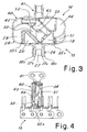
- each link 17, 18 comprises a pair of parallel plates 17a, 17b and 18a, 18b interconnected to the adjacent links by articulation pivots 26 that are transverse to the chain.
- the links of the chain have a bush or roller structure, with bushes fitted on interconnecting pivots in the case of bush chains and rollers 27 that are in turn fitted above the bushes in the case of a roller chain; links 17 with plates brought near one another are interspersed as links 18 with plates that are spaced further apart, according to known teachings.
- the positioning elements 19-22 extend as one piece from the plates of the links 17, 18.
- Each link comprises two positioning elements intended for being arranged on opposite sides of the sausage meat tube.
- Each plate 17a, 17b and 18a, 18b of a link is matched by a positioning element 19-22, as is clearly visible in figure 2 .
- the positioning elements define a longitudinal space inside which the sausage meat tube 15 is advanced during pinching operations.
- each positioning element 19-22 comprises a flat wall that is almost orthogonal to the movement direction of the chain, provided with an edge 19a, 20a, 21a, 22a intended for contacting the sausage meat tube.
- Such walls have a substantially triangular shape with the edge 19a, 20a, 21a, 22a arranged oblique to the plane of the plate of the link.
- the orthogonal flat wall 19b of a first positioning element 19 is near a front end of the link, whilst the flat wall 20b of the second positioning element 20 is near an opposite rear end of the link.
- the particular configuration of the elements 19-22 enables effective snap anchoring of the pinching element of the tube to be achieved. Further, positioning of the tube is improved owing to the fact that the walls 19b-20b are staggered in a longitudinal direction.
- the walls 20b and 19b extend from walls 23, 24 orthogonal to the plates 17a, 17b and protrude outside the link 17.
- the link 18 has a similar structure, with the triangular walls that form the supporting edges 21a, 22a arranged aligned on the triangular walls of the link 17.
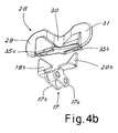
- pinching elements 28 also called “pinchers”
- the elements 28, 40 have the shape of a plate shaped with facing V-shaped profiles, between which there remains a gap 33 inside which the pinched part of the sausage meat tube 15 is pinched.
- each pinching element 28, 40 is fixable to a respective link 17, 41 of the chain at the positioning elements of the link.
- the element 28 is snap-fitted on a link 17.
- the pinching element 28 is provided with two hollow portions (or pockets) 35a and 35b open below, suitable for being snap-fitted or forced on the walls 19b, 20b of the link (as shown in figure 4b ).
- This teaching enables the distance between the pinching elements to be customized at will in a rapid and easy manner, whilst maintaining a firm link to the chain.
- Each pinching element 28 comprises a central wall 30 that is substantially transverse to the movement direction of the chain that has a V-shaped edge 32, 34 intended for cooperating with a similar V-shaped edge of the element 40.
- the two sides 32, 34 of the V-shaped edge have a tilt of approximately 45-50° with respect to the plane on which lie the adjacent portions of the two chains 13, 14.
- the wall 30 with a V-shaped edge of the pinching element 28 is slightly tilted with respect to the direction that is orthogonal to the conveying direction; the element 28 also comprises two external walls 29, 31 that are orthogonal to the sliding direction of the chain on opposite sides of the wall 30 with a V-shaped edge.
- the element 40 is shaped in a similar manner, with a central wall 43 slightly tilted with respect to a plane that is orthogonal to the sliding direction and a pair of external side walls 42, 44 that are orthogonal to the sliding direction.
- the particular shape of the elements 28, 40 enables optimum pinching of the sausage meat tube 15 to be obtained.
- the pinching elements are made of plastics, for example of Delrin.
- the links 17, 18, 40 are made of metal, for example of steel.
- the pinching element is anchored directly on the positioning elements of the link, and it is not necessary to provide a suitable link provided with specific means for anchoring the pinching element.
- the chain has a simplified lighter structure with a limited number of components, and is manufacturable cheaply. Further, cleaning of the chain is easier than with the chains used in the prior art as there are not numerous pieces fixed together.
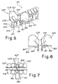
- the chain comprises links 117, 118, of the bush or roller chain type.
- Each link comprises a pair of plates 117a, 117b, interconnected to the plates of the adjacent links by articulation pivots.
- the positioning elements 119, 120 protrude as a piece from the plates of the link 117.
- the links 118, which have plates that are external to the links 117, have a similar shape, with the positioning elements aligned in a longitudinal direction compared with the elements 119, 120.
- the positioning elements 119, 120 differ from those of the first embodiment inasmuch as they have a wall that is parallel to the sliding direction of the chain, appropriately tilted to grasp the sausage meat tube 15 on one side.
- the pinching element 128 is riveted to a suitable link, which is different from the other links of the chain, provided with flanges 161, 163 that protrude as a piece from the plates of the link, laterally on opposite sides of the chain.
- the pinching element 128 comprises two portions of external wall 129, 131 that are slightly tilted with respect to a plane that is orthogonal to the sliding direction of the chain and a central wall 130 that joins the two portions 129, 131, which wall 130 has a greater tilt than the external portions.
- flanges 160, 165 extend in a piece for fixing to the flanges 161, 163 by rivets 162, 164.
- the links 217, 218 of the chain 213 are similar to 117, 118 disclosed for the second embodiment, with similar positioning elements 219, 220.
- the chain 213 differs from the chain 113 through the fact that the pinching element 228 is fixed to a link 217 shaped like the others at the positioning elements 219, 220 by rivets 262, 264.
- the pinching element 228 differs from the element 128 disclosed previously only for the lower profile, substantially V-shaped and provided with fixing flanges 260, 265 suitable for being superimposed on the positioning elements 219, 220. Also, the element 228 has portions of external wall 229, 231, between which there is a central portion 230 with a greater tilt than the plane that is orthogonal to the sliding direction of the chain. As in the other cases, the element 228 has an upper V-shaped profile for pinching the tube.
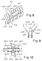
- FIG 11 there is shown a fourth embodiment of a chain 313 according to the invention, without the mounted pinching element.
- the chain has links of the bush or roller chain type.
- the plates 317a, 317b of the link 317 walls of one piece extend that are coplanar with the plate 349, 350, from the upper top of which walls, respectively 339 and 340, protrude laterally on opposite sides of the link.
- the walls 339 and 340 small triangular walls, respectively 319, 320, protrude that are orthogonal to the sliding direction of the chain and are provided with an oblique edge intended to act as a positioning element of the sausage meat tube.
- the pinching elements which are not shown, may be of the type that is similar to those already shown for the second embodiment of figures 5 to 8 , fixed with rivets to a suitable link of the chain provided with fixing flanges.
- FIG 12 there is shown a fifth alternative embodiment of the chain 413 according to the invention.
- the links 417 are similar to those 17 disclosed for the preferred embodiment, with positioning elements 419, 420 made of one piece with the plates 417a, 417b and comprising triangular walls that are orthogonal to the sliding direction of the chain. Unlike the link 17, the walls 419, 420 are positioned near the same end of the link, and are not longitudinally staggered.
- a suitable link with fixing flanges instead of the positioning elements, similarly to the second embodiment disclosed previously.
- FIG 13 there is shown a sixth embodiment of the invention, where also the chain 513 comprises links 517 of the bush or a roller chain type with plates 517a, 517b interconnected to the adjacent links by means of articulation pivots. From the plates 517a, 517b the positioning elements of the tube 519, 520 extend as a piece.
- the elements 519, 520 comprise oblique walls that are tilted both with respect to a plane that is orthogonal and to the sliding direction and to the sliding direction.
- a chain has been provided for machines for forming sausages that has a simplified structure and a limited number of pieces. This has enabled chain manufacturing costs to be reduced.
- the position of the pinching elements, in the event of snap-fitting on the links of the chain, can be customized in a rapid and easy manner.
Landscapes
- Engineering & Computer Science (AREA)
- Architecture (AREA)
- Civil Engineering (AREA)
- Structural Engineering (AREA)
- Life Sciences & Earth Sciences (AREA)
- Wood Science & Technology (AREA)
- Zoology (AREA)
- Food Science & Technology (AREA)
- Processing Of Meat And Fish (AREA)
- Meat, Egg Or Seafood Products (AREA)
- Chain Conveyers (AREA)
Claims (17)
- Kette zur Verwendung in einer Maschine zum Formen von Würsten oder dergleichen ausgehend von einem Wurstbrätschlauch (15), wobei die Kette beim Betrieb einen neben einem entsprechenden Abschnitt einer zweiten Kette der Vorrichtung angeordneten Abschnitt aufweist, wobei der Wurstbrätschlauch zwischen die zwei nebeneinander liegenden Abschnitte der zwei Ketten eingefügt ist, wobei die Kette eine Vielzahl von Gliedern (17, 18, 117, 118, 217, 218, 317, 417, 517) umfasst, die nacheinander miteinander verbunden sind und Abschnürelemente (28, 128, 228) zum Abschnüren des Wurstbrätschlauchs aufweisen, die passend sind, um entsprechenden Abschnürelementen (40) der zweiten Kette der Vorrichtung zu entsprechen, wobei die Kette außerdem Positionierelemente (19, 20, 119, 120, 219, 220, 319, 320, 419, 420, 519, 520) umfasst, die geeignet sind, den Wurstbrätschlauch (15) zumindest teilweise entlang dem neben der zweiten Kette liegenden Abschnitt zu ergreifen, dadurch gekennzeichnet, dass die Positionierelemente einstückig mit den Gliedern der Kette ausgeführt sind.
- Kette nach Anspruch 1, dadurch gekennzeichnet, dass jedes Glied ein Paar paralleler Platten (18a, 18b) umfasst, die mit Hilfe von jeweiligen Gelenkzapfen (26) mit den Platten (17a, 17b) der benachbarten Glieder verbunden sind.
- Kette nach Anspruch 2, dadurch gekennzeichnet, dass sich jedes Positionierelement einstückig von einer Platte eines Glieds ausdehnt.
- Kette nach Anspruch 1, dadurch gekennzeichnet, dass die Positionierelemente (19, 20) eine ebene Wand (19b, 20b) umfassen, die fast rechtwinklig zur Bewegungsrichtung der Kette ist und mit einer Kante (19a, 20a) versehen ist, die dazu bestimmt ist, den Wurstbrätschlauch zu berühren.
- Kette nach Anspruch 4, dadurch gekennzeichnet, dass die Wand (19b, 20b) etwa dreieckig ist und eine Berührungskante (19a, 20a) aufweist, die schräg zur Ebene der Platte des Glieds ist.
- Kette nach Anspruch 1, dadurch gekennzeichnet, dass jedes Glied (17, 18) zwei Positionierelemente umfasst, die dazu bestimmt sind, auf gegenüberliegenden Seiten des Wurstbrätschlauchs angeordnet zu sein.
- Kette nach Anspruch 4 und 6, dadurch gekennzeichnet, dass sich die ebene Wand (19b) eines ersten Positionierelements (19) eines Glieds (17) nahe bei einem vorderen Ende des Glieds befindet, wobei sich die ebene Wand (20b) des zweiten Positionierelements (20) des Glieds nahe bei einem hinteren Ende des Glieds befindet.
- Kette nach Anspruch 6, dadurch gekennzeichnet, dass jedes Abschnürelement (28, 40) zwei Taschen (35a, 35b) umfasst, die jeweils dazu geeignet sind, auf einer Wand (19b, 20b) von einem der Positionierelemente (19, 20) eines Glieds schnappbefestigt oder auf sie aufgepresst zu werden.
- Kette nach Anspruch 6, dadurch gekennzeichnet, dass die Positionierelemente (19, 20) eines Glieds in einer Längsrichtung zur Kette versetzt angeordnet sind.
- Kette nach Anspruch 1, dadurch gekennzeichnet, dass die Abschnürelemente aus Kunststoff bestehen.
- Kette nach Anspruch 1, dadurch gekennzeichnet, dass jedes Abschnürelement (28, 40, 228) an einem Glied der Kette an den Positionierelementen des Glieds befestigt werden kann.
- Kette nach Anspruch 1, dadurch gekennzeichnet, dass jedes Abschnürelement (28, 40) auf einem Glied der Kette schnappbefestigt werden kann.
- Kette nach Anspruch 1, dadurch gekennzeichnet, dass jedes Abschnürelement (128, 228) mit Nieten an einem Glied der Kette befestigt ist.
- Kette nach Anspruch 1, dadurch gekennzeichnet, dass jedes Abschnürelement (28, 128, 228) eine im Wesentlichen quer zur Bewegungsrichtung der Kette (13) angeordnete Wand umfasst, die eine V-förmige Kante aufweist, die dazu bestimmt ist, mit einer gleichartigen V-förmigen Kante eines entsprechenden Abschnürelements (40) der zweiten Kette (14) zum Abschnüren des Schlauchs (15) zusammenzuarbeiten.
- Kette nach Anspruch 14, dadurch gekennzeichnet, dass die zwei Seiten (32, 34) der V-förmigen Kante des Abschnürelements (28) eine Neigung von ungefähr 50° zu der Ebene aufweisen, auf der die zwei nebeneinander liegenden Abschnitte der zwei Ketten (13, 14) liegen.
- Kette nach Anspruch 14, dadurch gekennzeichnet, dass der Wandabschnitt (30) mit V-förmiger Kante des Abschnürelements gegenüber der Richtung, die rechtwinklig zur Gleitrichtung der Kette ist, leicht geneigt ist, wobei das Abschnürelement (28) auf gegenüberliegenden Seiten des Wandabschnitts mit einer V-förmigen Kante (30) zwei Wände (29, 31) umfasst, die rechtwinklig zu dieser Richtung sind.
- Maschine zum Formen von Würsten, umfassend eine Kette gemäß einem der Ansprüche 1 bis 16.
Applications Claiming Priority (2)
| Application Number | Priority Date | Filing Date | Title |
|---|---|---|---|
| IT000033U ITMI20070033U1 (it) | 2007-02-02 | 2007-02-02 | Catena per la formatura di salsicce o simili e macchina comprendente tale catena |
| PCT/EP2008/000704 WO2008092651A1 (en) | 2007-02-02 | 2008-01-30 | Chain for forming sausages or the like and machine comprising such a chain |
Publications (2)
| Publication Number | Publication Date |
|---|---|
| EP2117325A1 EP2117325A1 (de) | 2009-11-18 |
| EP2117325B1 true EP2117325B1 (de) | 2010-11-24 |
Family
ID=39673684
Family Applications (1)
| Application Number | Title | Priority Date | Filing Date |
|---|---|---|---|
| EP08707403A Not-in-force EP2117325B1 (de) | 2007-02-02 | 2008-01-30 | Kette zum formen von würsten oder dergleichen und maschine mit derartiger kette |
Country Status (9)
| Country | Link |
|---|---|
| US (1) | US20100105304A1 (de) |
| EP (1) | EP2117325B1 (de) |
| JP (1) | JP2010517517A (de) |
| CN (1) | CN101631467A (de) |
| AR (1) | AR065149A1 (de) |
| AT (1) | ATE489000T1 (de) |
| DE (1) | DE602008003672D1 (de) |
| IT (1) | ITMI20070033U1 (de) |
| WO (1) | WO2008092651A1 (de) |
Cited By (1)
| Publication number | Priority date | Publication date | Assignee | Title |
|---|---|---|---|---|
| EP4303141A1 (de) * | 2022-07-08 | 2024-01-10 | VEMAG Maschinenbau GmbH | Trennvorrichtung zum trennen von portionen aus mit lebensmittel-masse befüllten länglichen hüllen, betreffendes crimpelement sowie verfahren |
Families Citing this family (2)
| Publication number | Priority date | Publication date | Assignee | Title |
|---|---|---|---|---|
| JP7003942B2 (ja) * | 2019-01-21 | 2022-01-21 | 信越半導体株式会社 | ウェーハの評価方法 |
| DE102020124001B3 (de) * | 2020-09-15 | 2022-02-03 | Vemag Maschinenbau Gmbh | Portioniervorrichtung und -verfahren |
Family Cites Families (21)
| Publication number | Priority date | Publication date | Assignee | Title |
|---|---|---|---|---|
| US3694853A (en) * | 1970-11-09 | 1972-10-03 | Townsend Engineering Co | Apparatus for encasing a product |
| US3873744A (en) * | 1972-12-14 | 1975-03-25 | Townsend Engineering Co | Method of encasing a meat product |
| JPS5152485U (de) * | 1974-10-21 | 1976-04-21 | ||
| CH598766A5 (de) * | 1976-11-29 | 1978-05-12 | Hoegger & Cie Ag C | |
| JPS6128709U (ja) * | 1984-07-24 | 1986-02-20 | 大同工業株式会社 | V形サドル付チエ−ン |
| JPH0427869Y2 (de) * | 1985-02-19 | 1992-07-06 | ||
| JPS61200814U (de) * | 1985-06-04 | 1986-12-16 | ||
| JPS63277123A (ja) * | 1987-04-30 | 1988-11-15 | Kabaya Shokuhin Kk | 棒状物の搬送装置 |
| US5019012A (en) * | 1988-04-28 | 1991-05-28 | Townsend Engineering Company | Encased product and method and apparatus for encasing same |
| US4972547A (en) * | 1989-04-04 | 1990-11-27 | Townsend Engineering Company | Encased product and method and apparatus for encasing same |
| US6050888A (en) * | 1996-01-31 | 2000-04-18 | Hitech Co. Ltd. | Method and apparatus for manufacturing chain-like food products such as sausages or the like |
| US5709600A (en) * | 1996-03-27 | 1998-01-20 | Townsend Engineering Company | Method and means for linking and then separating encased sausage |
| IT1290475B1 (it) * | 1997-03-26 | 1998-12-04 | Righele Giovanni | Macchina per produrre salsicce con budello attorcigliato |
| WO2000065921A1 (en) * | 1999-05-02 | 2000-11-09 | Hitec Co., Ltd. | Method and device for manufacturing chain food such as sausage |
| JP4204145B2 (ja) * | 1999-08-16 | 2009-01-07 | ハイテック株式会社 | ソーセージ等の食品を製造する方法及び装置 |
| DE19952102A1 (de) * | 1999-10-29 | 2001-05-10 | Vemag Maschinen & Anlagenbau Gmbh | Verfahren und Vorrichtung zur Herstellung von kettenähnlichen Lebensmittelprodukten wie Würstchen oder dgl. |
| DE10013036A1 (de) * | 2000-03-17 | 2001-09-27 | Vemag Maschinenbau Gmbh | Verfahren und Vorrichtung zum Fördern und Vereinzeln von Würstchen oder dgl. |
| JP4601197B2 (ja) * | 2000-03-31 | 2010-12-22 | ハイテック株式会社 | ソーセージ等の捻り部を有したリンク状食品の製造装置 |
| ITMI20010682U1 (it) * | 2001-12-28 | 2003-06-28 | Regina Sud Spa | Maglia per trasportatore a catena con struttura migliorata |
| DE20220038U1 (de) * | 2002-12-20 | 2004-04-29 | Vemag Maschinenbau Gmbh | Portionier- und/oder Führungsvorrichtung |
| US7278536B1 (en) * | 2005-01-26 | 2007-10-09 | Habasit Ag | Molded plastic conveyor chain member for processing poultry |
-
2007
- 2007-02-02 IT IT000033U patent/ITMI20070033U1/it unknown
-
2008
- 2008-01-30 CN CN200880007830A patent/CN101631467A/zh active Pending
- 2008-01-30 US US12/449,190 patent/US20100105304A1/en not_active Abandoned
- 2008-01-30 AT AT08707403T patent/ATE489000T1/de not_active IP Right Cessation
- 2008-01-30 EP EP08707403A patent/EP2117325B1/de not_active Not-in-force
- 2008-01-30 DE DE602008003672T patent/DE602008003672D1/de active Active
- 2008-01-30 JP JP2009547593A patent/JP2010517517A/ja active Pending
- 2008-01-30 WO PCT/EP2008/000704 patent/WO2008092651A1/en not_active Ceased
- 2008-02-01 AR ARP080100443A patent/AR065149A1/es unknown
Cited By (3)
| Publication number | Priority date | Publication date | Assignee | Title |
|---|---|---|---|---|
| EP4303141A1 (de) * | 2022-07-08 | 2024-01-10 | VEMAG Maschinenbau GmbH | Trennvorrichtung zum trennen von portionen aus mit lebensmittel-masse befüllten länglichen hüllen, betreffendes crimpelement sowie verfahren |
| US12193449B2 (en) | 2022-07-08 | 2025-01-14 | Vemag Maschinenbau Gmbh | Separating device, related crimping element, and method |
| EP4303141B1 (de) | 2022-07-08 | 2025-01-29 | VEMAG Maschinenbau GmbH | Trennvorrichtung zum trennen von portionen aus mit lebensmittel-masse befüllten länglichen hüllen, betreffendes crimpelement sowie verfahren |
Also Published As
| Publication number | Publication date |
|---|---|
| WO2008092651A1 (en) | 2008-08-07 |
| DE602008003672D1 (de) | 2011-01-05 |
| EP2117325A1 (de) | 2009-11-18 |
| JP2010517517A (ja) | 2010-05-27 |
| CN101631467A (zh) | 2010-01-20 |
| ITMI20070033U1 (it) | 2008-08-03 |
| AR065149A1 (es) | 2009-05-20 |
| ATE489000T1 (de) | 2010-12-15 |
| US20100105304A1 (en) | 2010-04-29 |
Similar Documents
| Publication | Publication Date | Title |
|---|---|---|
| US4909380A (en) | Low backline pressure chain | |
| EP2176144B1 (de) | Modul mit grossem, offenem gelenk zur leichten reinigung | |
| EP2817249B1 (de) | Abriebfestes förderband | |
| US9073694B2 (en) | Conveyor belt | |
| EP2091848B1 (de) | Modulares Förderband mit spaltlosem Seitenschutz | |
| EP0919493A1 (de) | Modular strukturierte Platte zur Aufnahme durch einen Förderer zugeführter Produkt | |
| EP2117325B1 (de) | Kette zum formen von würsten oder dergleichen und maschine mit derartiger kette | |
| NZ200832A (en) | Conveyor chain link including rollers for low backline pressure chain | |
| US8157083B2 (en) | Self-clearing conveyor transfer system and transfer plate | |
| WO2011138607A2 (en) | Conveyors and transmission belts | |
| US8978881B2 (en) | Pivot rod and method of making thereof | |
| EP1836113B1 (de) | Förderband | |
| WO2000001599A1 (en) | Tapered side support for conveyor belts | |
| NL1034297C2 (nl) | Uit modules opgebouwde transportband en module. | |
| EP1723057A1 (de) | Biegbare rollfördereinrichtungsführung | |
| EP3152136A1 (de) | Kettenförderer | |
| EP3774600B1 (de) | Konsole für einen förderer | |
| EP0623531A2 (de) | Bandförderer zum Speichern | |
| AU2007219337A1 (en) | Lane divider for a plastic belt conveyor | |
| EP1702868A1 (de) | Förderband | |
| CN103842269B (zh) | 弯曲带式输送机和用于所述输送机的链 | |
| ITPD940165A1 (it) | Nastro trasportatore con catena continua per trasporti medio leggeri | |
| DK170366B1 (da) | Sidebøjelig transportkæde | |
| WO2006104380A1 (en) | Belt conveyor with curved sections |
Legal Events
| Date | Code | Title | Description |
|---|---|---|---|
| PUAI | Public reference made under article 153(3) epc to a published international application that has entered the european phase |
Free format text: ORIGINAL CODE: 0009012 |
|
| 17P | Request for examination filed |
Effective date: 20090728 |
|
| AK | Designated contracting states |
Kind code of ref document: A1 Designated state(s): AT BE BG CH CY CZ DE DK EE ES FI FR GB GR HR HU IE IS IT LI LT LU LV MC MT NL NO PL PT RO SE SI SK TR |
|
| RIN1 | Information on inventor provided before grant (corrected) |
Inventor name: BADDARIA, GIUSEPPE Inventor name: GARBAGNATI, CARLO |
|
| DAX | Request for extension of the european patent (deleted) | ||
| GRAP | Despatch of communication of intention to grant a patent |
Free format text: ORIGINAL CODE: EPIDOSNIGR1 |
|
| GRAS | Grant fee paid |
Free format text: ORIGINAL CODE: EPIDOSNIGR3 |
|
| GRAA | (expected) grant |
Free format text: ORIGINAL CODE: 0009210 |
|
| AK | Designated contracting states |
Kind code of ref document: B1 Designated state(s): AT BE BG CH CY CZ DE DK EE ES FI FR GB GR HR HU IE IS IT LI LT LU LV MC MT NL NO PL PT RO SE SI SK TR |
|
| REG | Reference to a national code |
Ref country code: GB Ref legal event code: FG4D |
|
| REG | Reference to a national code |
Ref country code: CH Ref legal event code: EP |
|
| REG | Reference to a national code |
Ref country code: IE Ref legal event code: FG4D |
|
| REF | Corresponds to: |
Ref document number: 602008003672 Country of ref document: DE Date of ref document: 20110105 Kind code of ref document: P |
|
| REG | Reference to a national code |
Ref country code: NL Ref legal event code: VDEP Effective date: 20101124 |
|
| LTIE | Lt: invalidation of european patent or patent extension |
Effective date: 20101124 |
|
| PG25 | Lapsed in a contracting state [announced via postgrant information from national office to epo] |
Ref country code: NO Free format text: LAPSE BECAUSE OF FAILURE TO SUBMIT A TRANSLATION OF THE DESCRIPTION OR TO PAY THE FEE WITHIN THE PRESCRIBED TIME-LIMIT Effective date: 20110224 Ref country code: LT Free format text: LAPSE BECAUSE OF FAILURE TO SUBMIT A TRANSLATION OF THE DESCRIPTION OR TO PAY THE FEE WITHIN THE PRESCRIBED TIME-LIMIT Effective date: 20101124 |
|
| PG25 | Lapsed in a contracting state [announced via postgrant information from national office to epo] |
Ref country code: SE Free format text: LAPSE BECAUSE OF FAILURE TO SUBMIT A TRANSLATION OF THE DESCRIPTION OR TO PAY THE FEE WITHIN THE PRESCRIBED TIME-LIMIT Effective date: 20101124 Ref country code: BG Free format text: LAPSE BECAUSE OF FAILURE TO SUBMIT A TRANSLATION OF THE DESCRIPTION OR TO PAY THE FEE WITHIN THE PRESCRIBED TIME-LIMIT Effective date: 20110224 Ref country code: SI Free format text: LAPSE BECAUSE OF FAILURE TO SUBMIT A TRANSLATION OF THE DESCRIPTION OR TO PAY THE FEE WITHIN THE PRESCRIBED TIME-LIMIT Effective date: 20101124 Ref country code: HR Free format text: LAPSE BECAUSE OF FAILURE TO SUBMIT A TRANSLATION OF THE DESCRIPTION OR TO PAY THE FEE WITHIN THE PRESCRIBED TIME-LIMIT Effective date: 20101124 Ref country code: AT Free format text: LAPSE BECAUSE OF FAILURE TO SUBMIT A TRANSLATION OF THE DESCRIPTION OR TO PAY THE FEE WITHIN THE PRESCRIBED TIME-LIMIT Effective date: 20101124 Ref country code: IS Free format text: LAPSE BECAUSE OF FAILURE TO SUBMIT A TRANSLATION OF THE DESCRIPTION OR TO PAY THE FEE WITHIN THE PRESCRIBED TIME-LIMIT Effective date: 20110324 Ref country code: FI Free format text: LAPSE BECAUSE OF FAILURE TO SUBMIT A TRANSLATION OF THE DESCRIPTION OR TO PAY THE FEE WITHIN THE PRESCRIBED TIME-LIMIT Effective date: 20101124 Ref country code: CY Free format text: LAPSE BECAUSE OF FAILURE TO SUBMIT A TRANSLATION OF THE DESCRIPTION OR TO PAY THE FEE WITHIN THE PRESCRIBED TIME-LIMIT Effective date: 20101124 Ref country code: LV Free format text: LAPSE BECAUSE OF FAILURE TO SUBMIT A TRANSLATION OF THE DESCRIPTION OR TO PAY THE FEE WITHIN THE PRESCRIBED TIME-LIMIT Effective date: 20101124 Ref country code: NL Free format text: LAPSE BECAUSE OF FAILURE TO SUBMIT A TRANSLATION OF THE DESCRIPTION OR TO PAY THE FEE WITHIN THE PRESCRIBED TIME-LIMIT Effective date: 20101124 Ref country code: PT Free format text: LAPSE BECAUSE OF FAILURE TO SUBMIT A TRANSLATION OF THE DESCRIPTION OR TO PAY THE FEE WITHIN THE PRESCRIBED TIME-LIMIT Effective date: 20110324 |
|
| PGFP | Annual fee paid to national office [announced via postgrant information from national office to epo] |
Ref country code: DE Payment date: 20110208 Year of fee payment: 4 |
|
| PG25 | Lapsed in a contracting state [announced via postgrant information from national office to epo] |
Ref country code: GR Free format text: LAPSE BECAUSE OF FAILURE TO SUBMIT A TRANSLATION OF THE DESCRIPTION OR TO PAY THE FEE WITHIN THE PRESCRIBED TIME-LIMIT Effective date: 20110225 |
|
| PG25 | Lapsed in a contracting state [announced via postgrant information from national office to epo] |
Ref country code: BE Free format text: LAPSE BECAUSE OF FAILURE TO SUBMIT A TRANSLATION OF THE DESCRIPTION OR TO PAY THE FEE WITHIN THE PRESCRIBED TIME-LIMIT Effective date: 20101124 Ref country code: EE Free format text: LAPSE BECAUSE OF FAILURE TO SUBMIT A TRANSLATION OF THE DESCRIPTION OR TO PAY THE FEE WITHIN THE PRESCRIBED TIME-LIMIT Effective date: 20101124 Ref country code: CZ Free format text: LAPSE BECAUSE OF FAILURE TO SUBMIT A TRANSLATION OF THE DESCRIPTION OR TO PAY THE FEE WITHIN THE PRESCRIBED TIME-LIMIT Effective date: 20101124 Ref country code: ES Free format text: LAPSE BECAUSE OF FAILURE TO SUBMIT A TRANSLATION OF THE DESCRIPTION OR TO PAY THE FEE WITHIN THE PRESCRIBED TIME-LIMIT Effective date: 20110307 |
|
| PG25 | Lapsed in a contracting state [announced via postgrant information from national office to epo] |
Ref country code: DK Free format text: LAPSE BECAUSE OF FAILURE TO SUBMIT A TRANSLATION OF THE DESCRIPTION OR TO PAY THE FEE WITHIN THE PRESCRIBED TIME-LIMIT Effective date: 20101124 Ref country code: RO Free format text: LAPSE BECAUSE OF FAILURE TO SUBMIT A TRANSLATION OF THE DESCRIPTION OR TO PAY THE FEE WITHIN THE PRESCRIBED TIME-LIMIT Effective date: 20101124 Ref country code: MC Free format text: LAPSE BECAUSE OF NON-PAYMENT OF DUE FEES Effective date: 20110131 Ref country code: PL Free format text: LAPSE BECAUSE OF FAILURE TO SUBMIT A TRANSLATION OF THE DESCRIPTION OR TO PAY THE FEE WITHIN THE PRESCRIBED TIME-LIMIT Effective date: 20101124 Ref country code: SK Free format text: LAPSE BECAUSE OF FAILURE TO SUBMIT A TRANSLATION OF THE DESCRIPTION OR TO PAY THE FEE WITHIN THE PRESCRIBED TIME-LIMIT Effective date: 20101124 |
|
| PLBE | No opposition filed within time limit |
Free format text: ORIGINAL CODE: 0009261 |
|
| STAA | Information on the status of an ep patent application or granted ep patent |
Free format text: STATUS: NO OPPOSITION FILED WITHIN TIME LIMIT |
|
| REG | Reference to a national code |
Ref country code: FR Ref legal event code: ST Effective date: 20110930 |
|
| REG | Reference to a national code |
Ref country code: IE Ref legal event code: MM4A |
|
| PG25 | Lapsed in a contracting state [announced via postgrant information from national office to epo] |
Ref country code: FR Free format text: LAPSE BECAUSE OF NON-PAYMENT OF DUE FEES Effective date: 20110131 |
|
| 26N | No opposition filed |
Effective date: 20110825 |
|
| REG | Reference to a national code |
Ref country code: DE Ref legal event code: R097 Ref document number: 602008003672 Country of ref document: DE Effective date: 20110825 |
|
| PG25 | Lapsed in a contracting state [announced via postgrant information from national office to epo] |
Ref country code: MT Free format text: LAPSE BECAUSE OF FAILURE TO SUBMIT A TRANSLATION OF THE DESCRIPTION OR TO PAY THE FEE WITHIN THE PRESCRIBED TIME-LIMIT Effective date: 20101124 |
|
| PG25 | Lapsed in a contracting state [announced via postgrant information from national office to epo] |
Ref country code: IE Free format text: LAPSE BECAUSE OF NON-PAYMENT OF DUE FEES Effective date: 20110130 |
|
| PGFP | Annual fee paid to national office [announced via postgrant information from national office to epo] |
Ref country code: IT Payment date: 20120126 Year of fee payment: 5 |
|
| REG | Reference to a national code |
Ref country code: CH Ref legal event code: PL |
|
| GBPC | Gb: european patent ceased through non-payment of renewal fee |
Effective date: 20120130 |
|
| PG25 | Lapsed in a contracting state [announced via postgrant information from national office to epo] |
Ref country code: LI Free format text: LAPSE BECAUSE OF NON-PAYMENT OF DUE FEES Effective date: 20120131 Ref country code: CH Free format text: LAPSE BECAUSE OF NON-PAYMENT OF DUE FEES Effective date: 20120131 Ref country code: GB Free format text: LAPSE BECAUSE OF NON-PAYMENT OF DUE FEES Effective date: 20120130 Ref country code: DE Free format text: LAPSE BECAUSE OF NON-PAYMENT OF DUE FEES Effective date: 20120801 |
|
| REG | Reference to a national code |
Ref country code: DE Ref legal event code: R119 Ref document number: 602008003672 Country of ref document: DE Effective date: 20120801 |
|
| PG25 | Lapsed in a contracting state [announced via postgrant information from national office to epo] |
Ref country code: LU Free format text: LAPSE BECAUSE OF NON-PAYMENT OF DUE FEES Effective date: 20110130 |
|
| PG25 | Lapsed in a contracting state [announced via postgrant information from national office to epo] |
Ref country code: TR Free format text: LAPSE BECAUSE OF FAILURE TO SUBMIT A TRANSLATION OF THE DESCRIPTION OR TO PAY THE FEE WITHIN THE PRESCRIBED TIME-LIMIT Effective date: 20101124 |
|
| PG25 | Lapsed in a contracting state [announced via postgrant information from national office to epo] |
Ref country code: HU Free format text: LAPSE BECAUSE OF FAILURE TO SUBMIT A TRANSLATION OF THE DESCRIPTION OR TO PAY THE FEE WITHIN THE PRESCRIBED TIME-LIMIT Effective date: 20101124 |
|
| PG25 | Lapsed in a contracting state [announced via postgrant information from national office to epo] |
Ref country code: IT Free format text: LAPSE BECAUSE OF NON-PAYMENT OF DUE FEES Effective date: 20140130 |