EP2116445A2 - Rear structure of vehicle body - Google Patents
Rear structure of vehicle body Download PDFInfo
- Publication number
- EP2116445A2 EP2116445A2 EP09159599A EP09159599A EP2116445A2 EP 2116445 A2 EP2116445 A2 EP 2116445A2 EP 09159599 A EP09159599 A EP 09159599A EP 09159599 A EP09159599 A EP 09159599A EP 2116445 A2 EP2116445 A2 EP 2116445A2
- Authority
- EP
- European Patent Office
- Prior art keywords
- rear side
- vehicle
- vehicle body
- crushed
- impact load
- Prior art date
- Legal status (The legal status is an assumption and is not a legal conclusion. Google has not performed a legal analysis and makes no representation as to the accuracy of the status listed.)
- Granted
Links
Images


Classifications
-
- B—PERFORMING OPERATIONS; TRANSPORTING
- B62—LAND VEHICLES FOR TRAVELLING OTHERWISE THAN ON RAILS
- B62D—MOTOR VEHICLES; TRAILERS
- B62D25/00—Superstructure or monocoque structure sub-units; Parts or details thereof not otherwise provided for
- B62D25/08—Front or rear portions
- B62D25/087—Luggage compartments
-
- B—PERFORMING OPERATIONS; TRANSPORTING
- B62—LAND VEHICLES FOR TRAVELLING OTHERWISE THAN ON RAILS
- B62D—MOTOR VEHICLES; TRAILERS
- B62D21/00—Understructures, i.e. chassis frame on which a vehicle body may be mounted
- B62D21/02—Understructures, i.e. chassis frame on which a vehicle body may be mounted comprising longitudinally or transversely arranged frame members
-
- B—PERFORMING OPERATIONS; TRANSPORTING
- B62—LAND VEHICLES FOR TRAVELLING OTHERWISE THAN ON RAILS
- B62D—MOTOR VEHICLES; TRAILERS
- B62D21/00—Understructures, i.e. chassis frame on which a vehicle body may be mounted
-
- B—PERFORMING OPERATIONS; TRANSPORTING
- B62—LAND VEHICLES FOR TRAVELLING OTHERWISE THAN ON RAILS
- B62D—MOTOR VEHICLES; TRAILERS
- B62D21/00—Understructures, i.e. chassis frame on which a vehicle body may be mounted
- B62D21/15—Understructures, i.e. chassis frame on which a vehicle body may be mounted having impact absorbing means, e.g. a frame designed to permanently or temporarily change shape or dimension upon impact with another body
- B62D21/152—Front or rear frames
Definitions
- the present invention generally relates to a rear structure of a vehicle body and particularly, but not exclusively, to a structure and technique for absorbing a rear impact. Aspects of the invention relate to a structure, to a method and to a vehicle.
- Patent Document 1 discloses a technique for absorbing an impact energy.
- a plurality of embosses are formed in rear side members, which are extended toward a rear direction of a vehicle and disposed at right and left sides.
- the embosses are compressed and destroyed. This causes the rear side member to buckle, which absorbs the impact energy.
- the impact load is received by only the rear side member at one side when there is an offset collision (i.e., when the impact load is exerted to the rear potion of the vehicle while being offset to any one side in a width direction of the vehicle).
- the rear side member does not buckle but rather bends toward an inner or outer side of the vehicle, the impact energy cannot be sufficiently absorbed.
- Embodiments of the invention may provide a structure in which, even in the case of an offset collision, an impact load can be effectively absorbed.
- Other aims and advantages of the invention will become apparent from the following description, claims and drawings.
- a rear structure of a vehicle body comprising a first rear side member and a second rear side member, the first and second rear side members generally extending in a front-to-rear direction of the vehicle body, a first rear cross member extending between the first rear side member and the second rear side member, a rear center member extending from the first rear cross member toward the rear of the vehicle body in the front-to-rear direction and the rear center member comprising at least one structure configured to be vulnerable when an impact load is exerted upon the rear of the vehicle body.
- the rear center member is substantially parallel to the first and second rear side members.
- first and second rear side members comprise extensions extending toward the rear of the vehicle in the front-to-rear direction.
- the structure may comprise a second rear cross member extending between the first rear side member and the second rear side member and positioned forward of the first rear cross member.
- the vulnerable structure comprises a first crushable portion configured to be crushed by the impact load first and a second crushable portion configured to be crushed after the first crushable portion is crushed.
- the rear center member comprises a bottom surface and a side wall at least partially surrounding the bottom surface.
- the first crushable portion comprises a first crumple zone formed in the bottom surface and a second crumple zone formed in the sidewall.
- the second crushable portion is disposed forward of the first crushable portion in the front-to-rear direction of the vehicle body.
- the second crushable portion comprises a reduced cross-sectional area.
- the second crushable portion comprises a ramp inclined upward and forward in the front-to-rear direction.
- the vulnerable structure is configured to crush into a rear floor panel of the vehicle when the impact load is exerted upon the rear of the vehicle body.
- the vulnerable structure of the rear center member comprises at least one emboss.
- the vulnerable structure is disposed at a coupling portion of the rear center member with the first rear cross member and comprises a portion of reduced cross-section between a starting point to the coupling portion.
- the starting point may be positioned rearward of the coupling portion in the front-to-rear direction.
- the portion of reduced cross-section is inclined upward and forward in the front-to-rear direction.
- a rear structure of a vehicle body comprising a first rear side member and a second rear side member, the first and second rear side members generally extending in a front-to-rear direction of the vehicle body, a first rear cross member extending between the first rear side member and the second rear side member, a rear center member extending from the first rear cross member toward the rear of the vehicle body in the front-to-rear direction and the rear center member comprising a means for collapsing configured to be crushed when an impact load is exerted upon the rear of the vehicle body.
- first and second rear side members comprise means for extending the first and second rear side members toward the rear of the vehicle in the front-to-rear direction.
- the means for collapsing comprises a first crushable portion configured to be crushed by the impact load and a second crushable portion configured to be crushed after the first deformable portion is crushed.
- the means for collapsing comprises at least one emboss.
- a method to absorb an impact to a rear structure of a vehicle body comprising disposing first and second rear side members in a front-to-rear direction to the vehicle body, extending a first rear cross member between the first and second rear side members, extending a rear center member from the first rear cross member toward the rear of the vehicle body in the front-to rear direction and providing at least one crushable portion to the rear center member, wherein the at least crushable portion is configured to be crushed by an impact load applied to the rear structure of the vehicle body.
- the crushable portion is configured to crush into a rear floor panel of the vehicle when the impact load is applied to the rear of the vehicle body.
- a rear structure of a vehicle body embodying one aspect of the invention may comprise a first rear side member and a second rear side member, the first and second rear side members generally extending in a front-to-rear direction of the vehicle body, a first rear cross member extending between the first rear side member and the second rear side member, a rear center member extending from the first rear cross member toward the rear of the vehicle body in the front-to-rear direction, and wherein the rear center member comprises at least one structure configured to be vulnerable when an impact load is exerted upon the rear of the vehicle body.
- a rear structure of a vehicle body embodying another aspect of the invention may comprise a first rear side member and a second rear side member, the first and second rear side members generally extending in a front-to-rear direction of the vehicle body, a first rear cross member extending between the first rear side member and the second rear side member, a rear center member extending from the first rear cross member toward the rear of the vehicle body in the front-to-rear direction, and wherein the rear center member comprises a means for collapsing configured to be crushed when an impact load is exerted upon the rear of the vehicle body.
- a method to absorb an impact to a rear structure of a vehicle body embodying an aspect of the invention may comprise disposing first and second rear side members in a front-to-rear direction to the vehicle body, extending a first rear cross member between the first and second rear side members, extending a rear center member from the first rear cross member toward the rear of the vehicle body in the front-to rear direction, and providing at least one crushable portion to the rear center member, wherein the at least crushable portion is configured to be crushed by an impact load applied to the rear structure of the vehicle body.
- the rear portion of a vehicle may be provided with a first rear side member and a second rear side member arranged at right and left sides. It may also provided with a rear cross member for connecting the rear side members. Further, a rear center member may be connected to the rear cross member between the first rear side member and the second rear side member, and approximately parallel to the rear side members. A fragile portion may be installed in the rear center member. With such an arrangement, even at the time of an offset collision, the input load may be exerted to any one of the rear side members and the rear center member. Additionally, since the rear center member is provided with the fragile portion, which is crushed by the input load, the rear center member may be crushed starting from the fragile portion. Thus, the impact energy asserted upon the rear portion of the vehicle can be sufficiently absorbed.
- Figures 1 to 7 illustrate a rear structure of a vehicle body according to embodiments of the present invention.
- an axis X indicates a front-to-rear direction of the vehicle
- an axis Y indicates a width direction of the vehicle
- an arrow FR indicates a front direction of the vehicle
- an arrow RR indicates a rear direction of the vehicle
- an axis Z indicates a height direction of the vehicle.
- the rear structure of the vehicle body comprises a first rear side member 1, a second rear side member 2, a first rear cross member 4, a second rear cross member 3, and a rear center member 5.
- the first rear side member 1 and the second rear side member 2 form a main framework of the rear portion of the vehicle and extend toward a rear direction RR of the vehicle. They are arranged at right and left sides by a desired distance in a width direction of the vehicle. Extension members 6 and 7 are respectively installed on rear distal ends of the first rear side member 1 and the second rear side member 2. The extension members 6 and 7 may be crushed when receiving the impact load to thereby absorb the impact energy.
- the second rear cross member 3 may be installed between the first rear side member 1 and the second rear side member 2 and extending in the width direction of the vehicle.
- the rigidity of the rear portion of the vehicle may be improved by connecting a first end of the second rear cross member 3 to the first rear side member 1 and a second end of the second rear cross member 3 to the second rear side member 2.
- the first rear cross member 4 may be installed at a vehicle rear direction of the second rear cross member 3 and may be configured to connect the first rear side member 1 and the second rear side member 2. Namely, a first end of the first rear cross member 4 may be connected to the first rear side member 1 and a second end of the first rear cross member 4 may be connected to the second rear side member 2.
- the first rear cross member 4 may be substantially parallel to the second rear cross member 3 to thereby form the rear portion of the vehicle body in a ladder shape when viewed from above, as shown in Figures 1 and 2 .
- a spare tire retaining member 9 for retaining a spare tire 8 may be installed at a lower surface 4a of the first rear cross member 4. The spare tire 8 may be retained by the spare tire retaining member 9 and a spare tire hanger (not shown) extended along the vehicle height direction.
- the rear center member 5 may be coupled to a vehicle rear side of the first rear cross member 4 between the first rear side member 1 and the second rear side member 2, and may be substantially parallel to such rear side members 1 and 2.
- the rear center member 5 may include a first member 10 and a second member 11.
- the first and second members, 10 and 11, may be coupled to surround an inner space to form at least a partially closed structure.
- a plurality of sacrificial crumple zones may be formed in the rear center member 5.
- the crumple zones may comprise beads, darts, embosses, ramps, ridges, bosses, or other similar structures.
- the crumple zones may be configured to crumple ( i . e ., be crushed) when an impact load F is applied at the rear of the vehicle in a direction toward the front of the vehicle (e.g., Figure 4 ).
- the crumple zones are configured to absorb and dissipate the kinetic energy of the impact load in an attempt to prevent damage to other vehicle body components and to reduce the effect of the impact load upon passengers of the vehicle.
- crumple zones and components containing crumple zones may be referred to as "sacrificial" or "energy dissipating" components of the vehicle body structure.
- the first member 10 may include a body 12 and a flange 13.
- the body 12 may, for example, be formed into a concave shape by executing a pressing operation on a flat metal plate to be recessed in a lower direction of the vehicle and to have a substantially rectangular shape when viewed from above, and may include a bottom surface 12a and sidewall 12b at least partially surrounding the bottom surface 12a.
- the flange 13 may be formed at an upper and outer periphery of the body 12.
- a vulnerable (i.e., sacrificial or energy dissipative) structure may be formed on the body portion 12.
- the vulnerable structure may include a first crumple zone 14, which may be formed as a convex shape from a bottom surface 12a toward an upper direction of the vehicle and may extend across the body 12 in a width direction of the vehicle.
- the first crumple zone 14 may serve as a first crushable portion, which may be a starting point to be crushed by the impact load from the rear direction of the vehicle.
- the vulnerable structure of body 12 of rear center member 5 may include one or more second crumple zones 15, which may also serve as part of the first crushable portion.
- the second crumple zones 15 may be formed at an inner side wall 12b of the body 12 and may be formed at a position closer to the front direction of the vehicle than a position where the first crumple zone 14 is formed.
- the second crumple zones 15 may comprise a V-shape vertically elongated toward the bottom surface 12a and indenting the flange 13.
- a plurality of second crumple zones 15 may be formed at the inner side wall 12b, for example at opposing sides of the side wall 12b in the width direction of the vehicle.
- a vulnerable structure of body portion 12 of rear center member 5 may comprise one or more first crumple zones 14, one or more second crumple zones 15, or a combination thereof.
- a third crumple zone 16 may be formed at a coupling edge 23 of the rear center member 5.
- the third crumple zone 16 may be formed as a ramp inclined from the vehicle rear direction toward the coupling edge 23 in the vehicle upper direction and vehicle forward direction.
- the cross-sectional area of the body 12 decreases when moving from the vehicle rear direction of the rear center member 5 toward the coupling portion 23.
- a vehicle forward end of the first member 10 may be formed as the third crumple zone 16.
- the coupling edge 23 between the first member 10 and the first rear cross member 4 may be formed with the flange 13 at a connecting side of the first member 10.
- the flange 13 may be welded or fixed to the first rear cross member 4.
- the second member 11 may be sized to be about between 1/3 and 1/2 of the size of the first member 10, and may be installed in the vehicle rear direction of the first member 10.
- the second member 11 may be formed by executing a pressing operation on a flat metal plate in a desired shape and may be integrated by being overlapped and welded or secured to the flange 13 of the first member 10.
- Through-holes 17 and 18 for a hook (not shown) for hanging one end of the spare tire hanger may be formed in the first and second members 10 and 11.
- the through-hole 18 formed in the first member 10 may be formed to be larger than the through-hole 17 formed in the second member 11. Because the larger through-hole 18 may be formed, the rigidity in this region may be weakened so that through-hole 18 may facilitate crushing of the rear center member 5 by the impact load.
- the impact load F may be exerted upon the extension members 6 and 7 of the first rear side member 1 and the second rear side member 2 and the rear center member 5 therebetween.
- a center collision means that the impactor 19 may impact the first rear side member 1, the second rear side member 2, and the rear center member 5.
- the extension members 6 and 7 may be crushed by the impact load F.
- the rear center member 5 may crush (buckle) starting from the first crushable portion (first crumple zone 14 and second crumple zone 15), and may be initially crushed by impact load F.
- a rear end region with the second member 11 may be crushed.
- the second crushable portion e.g., third crumple zone 16
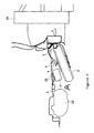
- the third crumple zone 16 may be formed from the ramp inclined from the bottom surface 12a of the body 12 in the upper direction of the vehicle toward the coupling edge 23, the third crumple zone 16 may buckle in a vehicle upper direction. Therefore, the vehicle rearward end of the rear center member 5 may be pushed upward and caused to contact a floor panel 20 of the vehicle, causing the rear floor panel 20 to be pushed upward in the vehicle upper direction.
- the upward movement of the rearward end of the rear center member 5 may allow the impactor 19 to exert the impact load F upon the spare tire 8, which may then pivot about a spare tire retaining member 9 so that the rearward end of the spare tire 8 may be lifted upward while the forward end of the spare tire 8 may be pushed downward.
- a canister 21 which may be located in the vehicle forward direction from the spare tire 8
- a situation may be prevented in which the spare tire 8 and the canister 21 are pushed down to crush a fuel tank 22, which may be arranged in the vehicle forward direction from the spare tire 8 and canister 21.
- the impact energy by the impactor 19 may be absorbed by the rear center member 5.
- the impact load F the energy of which may be absorbed and weakened because the rear center member 5 may be crushed, may be transferred via the first rear cross member 4 to the first rear side member 1 and the second rear side member 2 installed at both ends thereof.
- the impact load F may be decreased by a high rigidity region of the first rear side member 1 and the second rear side member 2 connected by the second rear cross member 3.
- the rear center member 5 may be installed between the first rear side member 1 and the second rear side member 2 and may be substantially parallel to such rear side members 1 and 2, the impact load F may be exerted upon the rear center member 5 and one of the first rear side member 1 or the second rear side member 2 in an offset collision.
- the impact load F may be received by the rear center member 5 and one of the first rear side member 1 or the second rear side member 2, instead of only one of the rear side members 1 and 2, the situation may be avoided in which the rear side members 1 or 2 are bent to the inner side in the width direction of the vehicle.
- the impact energy may be sufficiently absorbed.
- the rear center member 5 may be installed between the first rear side member 1 and the second rear side member 2 and may be substantially parallel to such rear side members 1 and 2, the impact load F may be exerted upon the rear center member 5 and one of the rear side members 1 or 2. Thus, the impact energy may be effectively absorbed.
- the vulnerable structure which may be crushed by the impact load F from the rear direction of the vehicle, may be installed or formed in the rear center member 5, when the impact load F may be impacted from the rear direction of the vehicle, the rear center member 5 may be crushed starting from the crushable portions to thereby sufficiently absorb the impact energy.
- the impact load F may be transferred via the first rear cross member 4 to the first rear side member 1 and the second rear side member 2 after the rear center member 5 may be crushed
- the impact load F (the energy of which may be absorbed by the rear center member 5 and thus lessened) may be transferred to both rear side members 1 and 2.
- the vulnerable structure may be formed from the first crushable portion initially crushed by the impact load F and the second crushable portion crushed after the first crushable portion may be crushed, the impact energy may be sequentially absorbed and the rear center member 5 may be completely crushed to efficiently absorb the impact load F and may control transfer of the impact load F to both rear side members 1 and 2.
- the first crushable portion may comprise the first crumple zone 14 and the second crumple zone 15 at two locations of the rear center member 5, the first crushable portion may comprise a simple structure.
- the second crushable portion may comprise the third crumple zone 16, which may be formed as a ramp inclined from the vehicle rear direction of the vehicle toward the coupling edge 23 in the vehicle upper direction and vehicle forward direction, the second crushable zone may be effectively crushed.
- the third crumple zone 16 may be formed from the ramp inclined in the upper direction of the vehicle toward the coupling edge 23, the rear floor panel 20 may be dislocated as it may be pushed up in the vehicle upper direction by the impact load F. Thus, it may be avoided that the spare tire 8 and the canister 21 may be pushed down in the vehicle forward direction to crush the fuel tank 22.
- the vulnerable structure of the rear center member 5 may be crushed to push up the rear floor panel 20 toward the upper direction of the vehicle, the canister 21 and fuel tank 22 installed at the lower surface of the vehicle may be protected at the time of collision.
- the vehicle forward end of the third crumple zone 16 of the rear center member 5 may be fixed at the lower surface 4a of the first rear cross member 4 rather than at the upper surface. By doing so, the amount of energy absorbed by the rear center member 5 may be increased.
- embodiments disclosed herein relate to providing a rear structure of a vehicle body wherein a rear side member may not bend toward the inner or outer side by the impact load from the rear of the vehicle even at the time of an offset collision, and wherein the rear structure is capable of sufficiently absorbing the impact energy therefrom.
- a rear cross member may be installed at a rear direction of the vehicle.
- the rear cross member may connect a first rear side member and a second rear side member arranged at right and left sides in a width direction of the vehicle.
- a rear center member may be connected to the rear cross member between the first and second rear side members, and substantially parallel to the rear side members. Additionally, a vulnerable structure may be integrated into the rear center member.
- the rear center member may be installed between the first and second rear side members, and substantially parallel to the rear side members. Further, it may be connected to the rear cross member.
- an impact load may be exerted to a rear side member at any one side and the rear center member even at the time of an offset collision. Therefore, because the vulnerable structure crushed by the impact load may be formed in the rear center member, the rear center member may be crushed starting from the vulnerable structure to thereby sufficiently absorb the impact energy exerted upon the rear portion of the vehicle.
Abstract
Description
- The present invention generally relates to a rear structure of a vehicle body and particularly, but not exclusively, to a structure and technique for absorbing a rear impact. Aspects of the invention relate to a structure, to a method and to a vehicle.
- Japanese Laid-Open Utility Model Publication No.
7-7265 Patent Document 1") discloses a technique for absorbing an impact energy. In this technique, a plurality of embosses are formed in rear side members, which are extended toward a rear direction of a vehicle and disposed at right and left sides. As such, when an impact load from a rear portion of the vehicle is exerted to a rear end of the rear side member, the embosses are compressed and destroyed. This causes the rear side member to buckle, which absorbs the impact energy. - However, in the technique disclosed in
Patent Document 1, the impact load is received by only the rear side member at one side when there is an offset collision (i.e., when the impact load is exerted to the rear potion of the vehicle while being offset to any one side in a width direction of the vehicle). As such, inPatent Document 1, because the rear side member does not buckle but rather bends toward an inner or outer side of the vehicle, the impact energy cannot be sufficiently absorbed. In particular, it is difficult to sufficiently absorb the rear impact energy for a vehicle in a short overhang type having a short length from the rear portion of a cabin of the vehicle to the rear end of the rear side member. - For example, in the case of an offset collision (i.e. a collision in which an impact load that is offset from the vehicle centerline is asserted on the rear portion of the vehicle), the impact load is received only by the rear side member at the side on which the impact is offset. Consequently, since the rear side member is not buckled but rather bends to an inner or outer side, it is difficult to absorb the impact energy.
- It is an aim of the present invention to address this issue and to improve upon known technology. Embodiments of the invention may provide a structure in which, even in the case of an offset collision, an impact load can be effectively absorbed. Other aims and advantages of the invention will become apparent from the following description, claims and drawings.
- Aspects of the invention therefore provide a rear structure, a method and a vehicle as claimed in the appended claims.
- According to another aspect of the invention for which protection is sought, there is provided a rear structure of a vehicle body, comprising a first rear side member and a second rear side member, the first and second rear side members generally extending in a front-to-rear direction of the vehicle body, a first rear cross member extending between the first rear side member and the second rear side member, a rear center member extending from the first rear cross member toward the rear of the vehicle body in the front-to-rear direction and the rear center member comprising at least one structure configured to be vulnerable when an impact load is exerted upon the rear of the vehicle body.
- In an embodiment, the rear center member is substantially parallel to the first and second rear side members.
- In an embodiment, the first and second rear side members comprise extensions extending toward the rear of the vehicle in the front-to-rear direction.
- The structure may comprise a second rear cross member extending between the first rear side member and the second rear side member and positioned forward of the first rear cross member.
- In an embodiment, the vulnerable structure comprises a first crushable portion configured to be crushed by the impact load first and a second crushable portion configured to be crushed after the first crushable portion is crushed.
- In an embodiment, the rear center member comprises a bottom surface and a side wall at least partially surrounding the bottom surface. In an embodiment, the first crushable portion comprises a first crumple zone formed in the bottom surface and a second crumple zone formed in the sidewall.
- In an embodiment, the second crushable portion is disposed forward of the first crushable portion in the front-to-rear direction of the vehicle body.
- In an embodiment, the second crushable portion comprises a reduced cross-sectional area.
- In an embodiment, the second crushable portion comprises a ramp inclined upward and forward in the front-to-rear direction.
- In an embodiment, the vulnerable structure is configured to crush into a rear floor panel of the vehicle when the impact load is exerted upon the rear of the vehicle body.
- In an embodiment, the vulnerable structure of the rear center member comprises at least one emboss.
- In an embodiment, the vulnerable structure is disposed at a coupling portion of the rear center member with the first rear cross member and comprises a portion of reduced cross-section between a starting point to the coupling portion. The starting point may be positioned rearward of the coupling portion in the front-to-rear direction.
- In an embodiment, the portion of reduced cross-section is inclined upward and forward in the front-to-rear direction.
- According to a further aspect of the invention for which protection is sought, there is provided a rear structure of a vehicle body, comprising a first rear side member and a second rear side member, the first and second rear side members generally extending in a front-to-rear direction of the vehicle body, a first rear cross member extending between the first rear side member and the second rear side member, a rear center member extending from the first rear cross member toward the rear of the vehicle body in the front-to-rear direction and the rear center member comprising a means for collapsing configured to be crushed when an impact load is exerted upon the rear of the vehicle body.
- In an embodiment, the first and second rear side members comprise means for extending the first and second rear side members toward the rear of the vehicle in the front-to-rear direction.
- In an embodiment, the means for collapsing comprises a first crushable portion configured to be crushed by the impact load and a second crushable portion configured to be crushed after the first deformable portion is crushed.
- In an embodiment, the means for collapsing comprises at least one emboss.
- According to a still further aspect of the invention for which protection is sought, there is provided a method to absorb an impact to a rear structure of a vehicle body, comprising disposing first and second rear side members in a front-to-rear direction to the vehicle body, extending a first rear cross member between the first and second rear side members, extending a rear center member from the first rear cross member toward the rear of the vehicle body in the front-to rear direction and providing at least one crushable portion to the rear center member, wherein the at least crushable portion is configured to be crushed by an impact load applied to the rear structure of the vehicle body.
- In an embodiment, the crushable portion is configured to crush into a rear floor panel of the vehicle when the impact load is applied to the rear of the vehicle body.
- For example, a rear structure of a vehicle body embodying one aspect of the invention may comprise a first rear side member and a second rear side member, the first and second rear side members generally extending in a front-to-rear direction of the vehicle body, a first rear cross member extending between the first rear side member and the second rear side member, a rear center member extending from the first rear cross member toward the rear of the vehicle body in the front-to-rear direction, and wherein the rear center member comprises at least one structure configured to be vulnerable when an impact load is exerted upon the rear of the vehicle body.
- A rear structure of a vehicle body embodying another aspect of the invention may comprise a first rear side member and a second rear side member, the first and second rear side members generally extending in a front-to-rear direction of the vehicle body, a first rear cross member extending between the first rear side member and the second rear side member, a rear center member extending from the first rear cross member toward the rear of the vehicle body in the front-to-rear direction, and wherein the rear center member comprises a means for collapsing configured to be crushed when an impact load is exerted upon the rear of the vehicle body.
- A method to absorb an impact to a rear structure of a vehicle body embodying an aspect of the invention may comprise disposing first and second rear side members in a front-to-rear direction to the vehicle body, extending a first rear cross member between the first and second rear side members, extending a rear center member from the first rear cross member toward the rear of the vehicle body in the front-to rear direction, and providing at least one crushable portion to the rear center member, wherein the at least crushable portion is configured to be crushed by an impact load applied to the rear structure of the vehicle body.
- In embodiments of the invention, the rear portion of a vehicle may be provided with a first rear side member and a second rear side member arranged at right and left sides. It may also provided with a rear cross member for connecting the rear side members. Further, a rear center member may be connected to the rear cross member between the first rear side member and the second rear side member, and approximately parallel to the rear side members. A fragile portion may be installed in the rear center member. With such an arrangement, even at the time of an offset collision, the input load may be exerted to any one of the rear side members and the rear center member. Additionally, since the rear center member is provided with the fragile portion, which is crushed by the input load, the rear center member may be crushed starting from the fragile portion. Thus, the impact energy asserted upon the rear portion of the vehicle can be sufficiently absorbed.
- Within the scope of this application it is envisaged that the various aspects, embodiments, examples, features and alternatives set out in the preceding paragraphs, in the claims and/or in the following description and drawings may be taken independently or in any combination thereof.
- The present invention will now be described, by way of example only, with reference to the accompanying drawings, in which:
-
Figure 1 is a perspective view of a rear structure of a vehicle body according to one embodiment of the present invention; -
Figure 2 is a bottom view of the rear structure shown inFigure 1 ; -
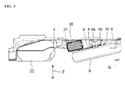
Figure 3 is a side view of the rear structure shown inFigure 1 ; -
Figure 4 is a side view of the rear structure when an impact load is exerted upon a rear portion of a vehicle; -
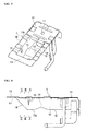
Figure 5 is a perspective view of a rear center member; -
Figure 6 is a side view of the rear center member; -
Figure 7(A) is a cross-sectional view of each position taken along the line A-A shown inFigure 6 ; -
Figure 7(B) is a cross-sectional view of each position taken along the line B-B shown inFigure 6 ; and -
Figure 7(C) is a cross-sectional view of each position taken along the line C-C shown inFigure 6 . -
Figures 1 to 7 illustrate a rear structure of a vehicle body according to embodiments of the present invention. - In
Figure 2 , an axis X indicates a front-to-rear direction of the vehicle, while an axis Y indicates a width direction of the vehicle. Further, an arrow FR indicates a front direction of the vehicle, while an arrow RR indicates a rear direction of the vehicle. InFigure 3 , an axis Z indicates a height direction of the vehicle. - As shown in
Figures 1 to 3 , the rear structure of the vehicle body according to embodiments disclosed herein comprises a firstrear side member 1, a secondrear side member 2, a firstrear cross member 4, a secondrear cross member 3, and arear center member 5. - The first
rear side member 1 and the secondrear side member 2 form a main framework of the rear portion of the vehicle and extend toward a rear direction RR of the vehicle. They are arranged at right and left sides by a desired distance in a width direction of the vehicle.Extension members rear side member 1 and the secondrear side member 2. Theextension members - In order to improve a rigidity of the rear portion of the vehicle, the second
rear cross member 3 may be installed between the firstrear side member 1 and the secondrear side member 2 and extending in the width direction of the vehicle. The rigidity of the rear portion of the vehicle may be improved by connecting a first end of the secondrear cross member 3 to the firstrear side member 1 and a second end of the secondrear cross member 3 to the secondrear side member 2. - The first
rear cross member 4 may be installed at a vehicle rear direction of the secondrear cross member 3 and may be configured to connect the firstrear side member 1 and the secondrear side member 2. Namely, a first end of the firstrear cross member 4 may be connected to the firstrear side member 1 and a second end of the firstrear cross member 4 may be connected to the secondrear side member 2. The firstrear cross member 4 may be substantially parallel to the secondrear cross member 3 to thereby form the rear portion of the vehicle body in a ladder shape when viewed from above, as shown inFigures 1 and2 . A sparetire retaining member 9 for retaining aspare tire 8 may be installed at alower surface 4a of the firstrear cross member 4. Thespare tire 8 may be retained by the sparetire retaining member 9 and a spare tire hanger (not shown) extended along the vehicle height direction. - The
rear center member 5 may be coupled to a vehicle rear side of the firstrear cross member 4 between the firstrear side member 1 and the secondrear side member 2, and may be substantially parallel to suchrear side members Figures 5 to 7 , therear center member 5 may include afirst member 10 and asecond member 11. The first and second members, 10 and 11, may be coupled to surround an inner space to form at least a partially closed structure. Further, a plurality of sacrificial crumple zones may be formed in therear center member 5. In certain embodiments, for example, the crumple zones may comprise beads, darts, embosses, ramps, ridges, bosses, or other similar structures. - Regardless of particular structure, the crumple zones may be configured to crumple (i.e., be crushed) when an impact load F is applied at the rear of the vehicle in a direction toward the front of the vehicle (e.g.,
Figure 4 ). As such, the crumple zones are configured to absorb and dissipate the kinetic energy of the impact load in an attempt to prevent damage to other vehicle body components and to reduce the effect of the impact load upon passengers of the vehicle. Thus, crumple zones and components containing crumple zones may be referred to as "sacrificial" or "energy dissipating" components of the vehicle body structure. - Referring again to
Figures 5-7 , thefirst member 10 may include abody 12 and aflange 13. Thebody 12 may, for example, be formed into a concave shape by executing a pressing operation on a flat metal plate to be recessed in a lower direction of the vehicle and to have a substantially rectangular shape when viewed from above, and may include abottom surface 12a andsidewall 12b at least partially surrounding thebottom surface 12a. Theflange 13 may be formed at an upper and outer periphery of thebody 12. A vulnerable (i.e., sacrificial or energy dissipative) structure may be formed on thebody portion 12. In particular, the vulnerable structure may include afirst crumple zone 14, which may be formed as a convex shape from abottom surface 12a toward an upper direction of the vehicle and may extend across thebody 12 in a width direction of the vehicle. Thefirst crumple zone 14 may serve as a first crushable portion, which may be a starting point to be crushed by the impact load from the rear direction of the vehicle. - Further, the vulnerable structure of
body 12 ofrear center member 5 may include one or moresecond crumple zones 15, which may also serve as part of the first crushable portion. Thesecond crumple zones 15 may be formed at aninner side wall 12b of thebody 12 and may be formed at a position closer to the front direction of the vehicle than a position where thefirst crumple zone 14 is formed. Thesecond crumple zones 15 may comprise a V-shape vertically elongated toward thebottom surface 12a and indenting theflange 13. As shown, a plurality ofsecond crumple zones 15 may be formed at theinner side wall 12b, for example at opposing sides of theside wall 12b in the width direction of the vehicle. However, those having ordinary skill will appreciate that a vulnerable structure ofbody portion 12 ofrear center member 5 may comprise one or morefirst crumple zones 14, one or moresecond crumple zones 15, or a combination thereof. - Further, a
third crumple zone 16 may be formed at acoupling edge 23 of therear center member 5. Thethird crumple zone 16 may be formed as a ramp inclined from the vehicle rear direction toward thecoupling edge 23 in the vehicle upper direction and vehicle forward direction. As shown inFigures 7(A), 7(B), and 7(C) , the cross-sectional area of thebody 12 decreases when moving from the vehicle rear direction of therear center member 5 toward thecoupling portion 23. As shown inFigure 6 , a vehicle forward end of thefirst member 10 may be formed as thethird crumple zone 16. - The
coupling edge 23 between thefirst member 10 and the firstrear cross member 4 may be formed with theflange 13 at a connecting side of thefirst member 10. Theflange 13 may be welded or fixed to the firstrear cross member 4. - In certain embodiments, the
second member 11 may be sized to be about between 1/3 and 1/2 of the size of thefirst member 10, and may be installed in the vehicle rear direction of thefirst member 10. Thesecond member 11 may be formed by executing a pressing operation on a flat metal plate in a desired shape and may be integrated by being overlapped and welded or secured to theflange 13 of thefirst member 10. - Through-
holes second members hole 18 formed in thefirst member 10 may be formed to be larger than the through-hole 17 formed in thesecond member 11. Because the larger through-hole 18 may be formed, the rigidity in this region may be weakened so that through-hole 18 may facilitate crushing of therear center member 5 by the impact load. - As shown in
Figure 4 , when an impactor 19 collides in a center collision from the rear direction toward the front direction of the vehicle with the impact load F, the impact load F may be exerted upon theextension members rear side member 1 and the secondrear side member 2 and therear center member 5 therebetween. A center collision means that the impactor 19 may impact the firstrear side member 1, the secondrear side member 2, and therear center member 5. Theextension members rear center member 5 may crush (buckle) starting from the first crushable portion (first crumple zone 14 and second crumple zone 15), and may be initially crushed by impact load F. - Further, starting from the crushing of the first crushable portion (e.g.,
first crumple zone 14 and second crumple zone 15) a rear end region with thesecond member 11 may be crushed. Then, the second crushable portion (e.g., third crumple zone 16) may be crushed. Because thethird crumple zone 16 may be formed from the ramp inclined from thebottom surface 12a of thebody 12 in the upper direction of the vehicle toward thecoupling edge 23, thethird crumple zone 16 may buckle in a vehicle upper direction. Therefore, the vehicle rearward end of therear center member 5 may be pushed upward and caused to contact afloor panel 20 of the vehicle, causing therear floor panel 20 to be pushed upward in the vehicle upper direction. The upward movement of the rearward end of therear center member 5 may allow the impactor 19 to exert the impact load F upon thespare tire 8, which may then pivot about a sparetire retaining member 9 so that the rearward end of thespare tire 8 may be lifted upward while the forward end of thespare tire 8 may be pushed downward. Thus, contact and interference between the forward end of the spare tire and acanister 21, which may be located in the vehicle forward direction from thespare tire 8, may be avoided. Accordingly, a situation may be prevented in which thespare tire 8 and thecanister 21 are pushed down to crush afuel tank 22, which may be arranged in the vehicle forward direction from thespare tire 8 andcanister 21. - As such, because the
rear center member 5 may be crushed starting from the crushing of the first and second crushable portions, the impact energy by the impactor 19 may be absorbed by therear center member 5. The impact load F, the energy of which may be absorbed and weakened because therear center member 5 may be crushed, may be transferred via the firstrear cross member 4 to the firstrear side member 1 and the secondrear side member 2 installed at both ends thereof. The impact load F may be decreased by a high rigidity region of the firstrear side member 1 and the secondrear side member 2 connected by the secondrear cross member 3. - In the case of an offset collision, according to embodiments disclosed herein, because the
rear center member 5 may be installed between the firstrear side member 1 and the secondrear side member 2 and may be substantially parallel to suchrear side members rear center member 5 and one of the firstrear side member 1 or the secondrear side member 2 in an offset collision. As such, because the impact load F may be received by therear center member 5 and one of the firstrear side member 1 or the secondrear side member 2, instead of only one of therear side members rear side members - As described above, according to embodiments disclosed herein, because the
rear center member 5 may be installed between the firstrear side member 1 and the secondrear side member 2 and may be substantially parallel to suchrear side members rear center member 5 and one of therear side members - Further, according to embodiments disclosed herein, because the vulnerable structure, which may be crushed by the impact load F from the rear direction of the vehicle, may be installed or formed in the
rear center member 5, when the impact load F may be impacted from the rear direction of the vehicle, therear center member 5 may be crushed starting from the crushable portions to thereby sufficiently absorb the impact energy. - Additionally, according to embodiments disclosed herein, because it may be configured that the impact load F may be transferred via the first
rear cross member 4 to the firstrear side member 1 and the secondrear side member 2 after therear center member 5 may be crushed, the impact load F (the energy of which may be absorbed by therear center member 5 and thus lessened) may be transferred to bothrear side members - Further, according to embodiments disclosed herein, because the vulnerable structure may be formed from the first crushable portion initially crushed by the impact load F and the second crushable portion crushed after the first crushable portion may be crushed, the impact energy may be sequentially absorbed and the
rear center member 5 may be completely crushed to efficiently absorb the impact load F and may control transfer of the impact load F to bothrear side members - Also, according to embodiments disclosed herein, because the first crushable portion may comprise the
first crumple zone 14 and thesecond crumple zone 15 at two locations of therear center member 5, the first crushable portion may comprise a simple structure. - Further, according to embodiments disclosed herein, because the second crushable portion may comprise the
third crumple zone 16, which may be formed as a ramp inclined from the vehicle rear direction of the vehicle toward thecoupling edge 23 in the vehicle upper direction and vehicle forward direction, the second crushable zone may be effectively crushed. - Additionally, according to embodiments disclosed herein, because the
third crumple zone 16 may be formed from the ramp inclined in the upper direction of the vehicle toward thecoupling edge 23, therear floor panel 20 may be dislocated as it may be pushed up in the vehicle upper direction by the impact load F. Thus, it may be avoided that thespare tire 8 and thecanister 21 may be pushed down in the vehicle forward direction to crush thefuel tank 22. - Further, according to embodiments disclosed herein, because the vulnerable structure of the
rear center member 5 may be crushed to push up therear floor panel 20 toward the upper direction of the vehicle, thecanister 21 andfuel tank 22 installed at the lower surface of the vehicle may be protected at the time of collision. - While embodiments of the present invention are described above, the present invention may include other embodiments and modifications without deviating from the subject matter or scope of the disclosure.
- For example, the vehicle forward end of the
third crumple zone 16 of therear center member 5 may be fixed at thelower surface 4a of the firstrear cross member 4 rather than at the upper surface. By doing so, the amount of energy absorbed by therear center member 5 may be increased. - Advantageously, embodiments disclosed herein relate to providing a rear structure of a vehicle body wherein a rear side member may not bend toward the inner or outer side by the impact load from the rear of the vehicle even at the time of an offset collision, and wherein the rear structure is capable of sufficiently absorbing the impact energy therefrom.
- Advantageously, a rear cross member may be installed at a rear direction of the vehicle. The rear cross member may connect a first rear side member and a second rear side member arranged at right and left sides in a width direction of the vehicle. Further, a rear center member may be connected to the rear cross member between the first and second rear side members, and substantially parallel to the rear side members. Additionally, a vulnerable structure may be integrated into the rear center member.
- Advantageously, the rear center member may be installed between the first and second rear side members, and substantially parallel to the rear side members. Further, it may be connected to the rear cross member. Thus, an impact load may be exerted to a rear side member at any one side and the rear center member even at the time of an offset collision. Therefore, because the vulnerable structure crushed by the impact load may be formed in the rear center member, the rear center member may be crushed starting from the vulnerable structure to thereby sufficiently absorb the impact energy exerted upon the rear portion of the vehicle.
- While the disclosure has been presented with respect to a limited number of embodiments, those skilled in the art, having benefit of this disclosure, will appreciate that other embodiments may be devised which do not depart from the scope of the present invention. Accordingly, the scope of the invention should be limited only by the attached claims.
- The present application claims priority from Japanese Patent Application Nos.
2008-123423, filed 9th May 2008 2009-033710, filed 17th February 2009
Claims (15)
- A rear structure for a vehicle body, comprising:a first rear side member and a second rear side member, the first and second rear side members generally extending in a front-to-rear direction of the vehicle body;a first rear cross member extending between the first rear side member and the second rear side member; anda rear center member extending from the first rear cross member toward the rear of the vehicle body in the front-to-rear direction;wherein the rear center member comprises at least one vulnerable structure configured to collapse and/or be crushed when an impact load is exerted upon the rear of the vehicle body.
- A rear structure as claimed in claim 1, wherein the rear center member is substantially parallel to the first and second rear side members.
- A rear structure as claimed in claim 1 or claim 2, wherein the first and second rear side members comprise extensions extending toward the rear of the vehicle in the front-to-rear direction.
- A rear structure as claimed in any preceding claim, comprising a second rear cross member extending between the first rear side member and the second rear side member and positioned forward of the first rear cross member.
- A rear structure as claimed in any preceding claim, wherein the vulnerable structure comprises:a first crushable portion configured to be crushed by the impact load first; anda second crushable portion configured to be crushed after the first crushable portion is crushed.
- A rear structure as claimed in claim 5, wherein the rear center member comprises a bottom surface and a side wall at least partially surrounding the bottom surface.
- A rear structure as claimed in claim 6, wherein the first crushable portion comprises a first crumple zone formed in the bottom surface and a second crumple zone formed in the sidewall.
- A rear structure as claimed in any of claims 5 to 7, wherein the second crushable portion is disposed forward of the first crushable portion in the front-to-rear direction of the vehicle body.
- A rear structure as claimed in any of claims 5 to 8, wherein the second crushable portion comprises:a reduced cross-sectional area; and/ora ramp inclined upward and forward in the front-to-rear direction.
- A rear structure as claimed in any preceding claim, wherein the vulnerable structure is configured to crush into a rear floor panel of the vehicle when the impact load is exerted upon the rear of the vehicle body.
- A rear structure as claimed in any preceding claim, wherein the vulnerable structure of the rear center member comprises at least one emboss.
- A rear structure as claimed in any preceding claim, wherein the vulnerable structure is disposed at a coupling portion of the rear center member with the first rear cross member and comprises a portion of reduced cross-section between a starting point to the coupling portion, the starting point being positioned rearward of the coupling portion in the front-to-rear direction.
- A rear structure as claimed in claim 12, wherein the portion of reduced cross-section is inclined upward and forward in the front-to-rear direction.
- A method of absorbing an impact to a rear structure of a vehicle body, comprising:disposing first and second rear side members in a front-to-rear direction to the vehicle body;extending a first rear cross member between the first and second rear side members;extending a rear center member from the first rear cross member toward the rear of the vehicle body in the front-to rear direction; andproviding at least one crushable portion to the rear center member, wherein the at least crushable portion is configured to be crushed by an impact load applied to the rear structure of the vehicle body.
- A vehicle having a rear structure or adapted to use a method as claimed in any preceding claim.
Applications Claiming Priority (2)
| Application Number | Priority Date | Filing Date | Title |
|---|---|---|---|
| JP2008123423 | 2008-05-09 | ||
| JP2009033710A JP5417878B2 (en) | 2008-05-09 | 2009-02-17 | Rear structure of automobile body |
Publications (3)
| Publication Number | Publication Date |
|---|---|
| EP2116445A2 true EP2116445A2 (en) | 2009-11-11 |
| EP2116445A3 EP2116445A3 (en) | 2009-11-18 |
| EP2116445B1 EP2116445B1 (en) | 2011-04-13 |
Family
ID=40756650
Family Applications (1)
| Application Number | Title | Priority Date | Filing Date |
|---|---|---|---|
| EP09159599A Active EP2116445B1 (en) | 2008-05-09 | 2009-05-07 | Rear structure of vehicle body |
Country Status (7)
| Country | Link |
|---|---|
| US (1) | US8657364B2 (en) |
| EP (1) | EP2116445B1 (en) |
| JP (1) | JP5417878B2 (en) |
| KR (2) | KR20090117644A (en) |
| CN (1) | CN101574980B (en) |
| AT (1) | ATE505390T1 (en) |
| DE (1) | DE602009001039D1 (en) |
Families Citing this family (15)
| Publication number | Priority date | Publication date | Assignee | Title |
|---|---|---|---|---|
| JP5509842B2 (en) * | 2009-12-25 | 2014-06-04 | マツダ株式会社 | Rear body structure of the vehicle |
| CN102465659B (en) * | 2010-11-12 | 2015-06-24 | 皇田工业股份有限公司 | Edging hooking device of curtain |
| DE112013002970T5 (en) * | 2012-06-15 | 2015-03-12 | Honda Motor Co., Ltd. | Structure for rear part of vehicle body |
| FR2997373A1 (en) * | 2012-10-29 | 2014-05-02 | Renault Sa | METHOD FOR MANUFACTURING A REAR FLOOR OF A MOTOR VEHICLE AND REAR FLOOR PRODUCED BY SUCH A METHOD |
| CN103847794B (en) * | 2012-12-03 | 2015-12-23 | 上汽通用五菱汽车股份有限公司 | A kind of vehicle frame rear structure |
| US8857898B1 (en) * | 2013-08-09 | 2014-10-14 | Ford Global Technologies, Llc | Spare-tire collision management system |
| CN104369770A (en) * | 2013-08-17 | 2015-02-25 | 江苏卡威汽车工业集团有限公司 | Rear floor frame |
| JP6252560B2 (en) * | 2015-07-27 | 2017-12-27 | トヨタ自動車株式会社 | Vehicle rear structure |
| FR3060507B1 (en) * | 2016-12-16 | 2019-01-25 | Peugeot Citroen Automobiles Sa | REAR STRUCTURE OF A MOTOR VEHICLE COMPRISING A REINFORCEMENT FOR COLLISIONS AT THE BACK |
| JP6575917B2 (en) | 2017-07-06 | 2019-09-18 | 本田技研工業株式会社 | Car body rear structure |
| US10202028B1 (en) * | 2017-08-09 | 2019-02-12 | Ford Global Technologies, Llc | Vehicle Traction Battery Sub-Frame Assembly |
| JP6624526B2 (en) * | 2018-02-15 | 2019-12-25 | 本田技研工業株式会社 | Body structure |
| CN111954618B (en) * | 2018-04-11 | 2022-05-24 | 本田技研工业株式会社 | Body structure of automobile |
| JP7156991B2 (en) * | 2019-03-29 | 2022-10-19 | 本田技研工業株式会社 | Subframe structure |
| US11117619B2 (en) | 2019-09-09 | 2021-09-14 | Ford Global Technologies, Llc | Vehicle frame assembly |
Citations (1)
| Publication number | Priority date | Publication date | Assignee | Title |
|---|---|---|---|---|
| JPH077265Y2 (en) | 1989-02-17 | 1995-02-22 | ダイハツ工業株式会社 | Automobile shock absorption structure |
Family Cites Families (59)
| Publication number | Priority date | Publication date | Assignee | Title |
|---|---|---|---|---|
| US2195688A (en) * | 1935-11-06 | 1940-04-02 | Windberger Othmar | Motor vehicle |
| US2823068A (en) * | 1954-10-05 | 1958-02-11 | Walker Brooks | Vehicle spare tire mounting |
| US3595335A (en) * | 1969-09-25 | 1971-07-27 | Budd Co | Front end vehicle body structure |
| US3848886A (en) * | 1972-10-05 | 1974-11-19 | Ford Motor Co | Body support and impact absorbing frame system for a motor vehicle |
| US3870341A (en) * | 1973-08-29 | 1975-03-11 | Dwen R Younger | Straddle trailer hitch |
| US3912295A (en) * | 1974-03-04 | 1975-10-14 | Budd Co | Crash energy-attenuating means for a vehicle frame construction |
| FR2317152A1 (en) * | 1975-07-07 | 1977-02-04 | Peugeot | DEVICE FOR STORING A SPARE WHEEL ON A MOTOR VEHICLE |
| JPS57172882A (en) * | 1981-04-15 | 1982-10-23 | Nissan Motor Co Ltd | Spare tire loading device |
| US4514008A (en) * | 1981-06-05 | 1985-04-30 | Toyota Jidosha Kogyo Kabushiki Kaisha | Vehicle body floor construction of motor vehicle |
| US5018780A (en) * | 1985-10-01 | 1991-05-28 | Mazda Motor Corporation | Vehicle lower body structure |
| US4958870A (en) * | 1988-09-30 | 1990-09-25 | Bernie Carter | Combination bumper and tire storage compartment with tire lock mechanism |
| JP2839658B2 (en) * | 1989-07-03 | 1998-12-16 | マツダ株式会社 | Rear body structure of vehicle |
| JPH0353384U (en) * | 1989-09-30 | 1991-05-23 | ||
| JP2991311B2 (en) * | 1991-03-30 | 1999-12-20 | マツダ株式会社 | Body rear structure |
| US5419609A (en) * | 1993-01-07 | 1995-05-30 | Ford Motor Company | Energy isolation apparatus for an automotive vehicle |
| JPH077265A (en) | 1993-06-15 | 1995-01-10 | Dainippon Toryo Co Ltd | Manufacture of printed wiring board |
| CA2136134C (en) * | 1994-04-25 | 1999-07-27 | James E. Borchelt | Light weight steel auto body construction |
| US5429388A (en) * | 1994-05-09 | 1995-07-04 | Ford Motor Company | Angular and frontal energy absorbing vehicle frame structure |
| JP3434069B2 (en) * | 1995-02-17 | 2003-08-04 | 本田技研工業株式会社 | Body rear structure |
| US5788322A (en) * | 1995-12-13 | 1998-08-04 | Dr. Ing. H.C.F. Porsche Ag | Body structure for a rear carriage of a convertible |
| JP3738508B2 (en) * | 1996-12-13 | 2006-01-25 | 日産自動車株式会社 | Body front frame structure |
| US5853195A (en) * | 1997-01-16 | 1998-12-29 | Ford Global Technologies, Inc. | Front rail assembly for a vehicle |
| US5860687A (en) * | 1997-12-19 | 1999-01-19 | Chrysler Corporation | Vehicle spare tire storage system having stiffening plate |
| DE19913532B4 (en) | 1998-03-26 | 2006-01-26 | Wagon Automotive Gmbh | Motor vehicle body and stiffening frame for a motor vehicle body |
| DE19829432C2 (en) | 1998-07-01 | 2003-07-17 | Daimler Chrysler Ag | Floor structure for a self-supporting bodyshell of a motor vehicle |
| JP2000255455A (en) | 1999-03-08 | 2000-09-19 | Mitsubishi Motors Corp | Car body structure |
| US6655896B2 (en) * | 1999-10-29 | 2003-12-02 | Accubuilt, Inc. | Vehicle with full size spare tire conversion and lifting mechanism |
| JP3828329B2 (en) * | 2000-02-18 | 2006-10-04 | 日産自動車株式会社 | Auto body structure |
| US6293587B1 (en) * | 2000-03-17 | 2001-09-25 | Dana Corporation | Vehicle body and frame assembly including energy absorbing structure |
| JP3644395B2 (en) | 2001-03-15 | 2005-04-27 | 日産自動車株式会社 | Automotive power unit layout |
| JP2002321642A (en) | 2001-04-25 | 2002-11-05 | Fuji Heavy Ind Ltd | Rear body structure of automobile |
| JP4593014B2 (en) * | 2001-06-05 | 2010-12-08 | 富士重工業株式会社 | Rear body structure of automobile |
| JP3574091B2 (en) * | 2001-06-12 | 2004-10-06 | 本田技研工業株式会社 | Rear body structure |
| JP4010817B2 (en) * | 2002-01-30 | 2007-11-21 | 本田技研工業株式会社 | Vehicle body frame structure |
| JP4168812B2 (en) * | 2003-04-07 | 2008-10-22 | 三菱自動車工業株式会社 | Connecting structure at the rear of the car body |
| US6830287B1 (en) * | 2003-07-24 | 2004-12-14 | Ford Global Technologies, Llc | Rear rail neutralizing member |
| DE102004008435B4 (en) | 2004-02-19 | 2008-11-13 | Benteler Automobiltechnik Gmbh | In the area of the crash box reinforced cross member |
| US7389860B2 (en) | 2004-03-29 | 2008-06-24 | The Texas A&M University System | Energy absorbing device having notches and pre-bent sections |
| JP4251562B2 (en) | 2004-07-20 | 2009-04-08 | 本田技研工業株式会社 | Bumper beam for vehicles |
| JP2006082742A (en) * | 2004-09-17 | 2006-03-30 | Suzuki Motor Corp | Rear body structure |
| JP4771677B2 (en) | 2004-09-21 | 2011-09-14 | スズキ株式会社 | Car body rear structure |
| US7699346B2 (en) * | 2005-03-23 | 2010-04-20 | Chrysler Group Llc | Force redistributing system for a vehicle in the event of a rear impact |
| JP2007038839A (en) * | 2005-08-03 | 2007-02-15 | Mazda Motor Corp | Rear part car body structure for vehicle |
| JP4404036B2 (en) * | 2005-09-21 | 2010-01-27 | トヨタ自動車株式会社 | Vehicle rear structure |
| JP4752453B2 (en) * | 2005-10-27 | 2011-08-17 | 日産自動車株式会社 | Spare tire storage structure |
| JP4640125B2 (en) | 2005-11-14 | 2011-03-02 | スズキ株式会社 | Undercarriage of the vehicle |
| JP4654917B2 (en) * | 2006-01-12 | 2011-03-23 | 日産自動車株式会社 | Car body rear structure |
| JP4478654B2 (en) * | 2006-02-13 | 2010-06-09 | 本田技研工業株式会社 | Body floor structure |
| JP4813251B2 (en) * | 2006-05-12 | 2011-11-09 | 本田技研工業株式会社 | Subframe and subframe manufacturing method |
| JP5001608B2 (en) * | 2006-09-04 | 2012-08-15 | 本田技研工業株式会社 | Rear body structure |
| JP4301271B2 (en) * | 2006-09-12 | 2009-07-22 | 日産自動車株式会社 | Auto body structure |
| US7731257B2 (en) * | 2006-09-22 | 2010-06-08 | Ford Global Technologies | Collision management system for compartment-mounted automotive spare tire |
| JP5032853B2 (en) * | 2007-01-19 | 2012-09-26 | 本田技研工業株式会社 | Car body rear structure |
| JP4917958B2 (en) * | 2007-05-08 | 2012-04-18 | 本田技研工業株式会社 | Car body rear structure |
| WO2009001655A1 (en) * | 2007-06-22 | 2008-12-31 | Honda Motor Co., Ltd. | Rear vehicle body structure |
| US7527327B2 (en) * | 2007-09-18 | 2009-05-05 | Ford Global Technologies, Llc | Rear vehicle subassembly having a towing hitch member |
| JP4572241B2 (en) * | 2008-01-31 | 2010-11-04 | 本田技研工業株式会社 | Rear body structure of automobile |
| JP5257610B2 (en) * | 2009-03-10 | 2013-08-07 | 三菱自動車工業株式会社 | Vehicle collision detection structure |
| US8292356B2 (en) * | 2009-03-17 | 2012-10-23 | Mazda Motor Corporation | Lower vehicle-body structure of vehicle |
-
2009
- 2009-02-17 JP JP2009033710A patent/JP5417878B2/en not_active Expired - Fee Related
- 2009-04-03 US US12/418,502 patent/US8657364B2/en active Active
- 2009-04-30 CN CN2009101322980A patent/CN101574980B/en not_active Expired - Fee Related
- 2009-05-07 EP EP09159599A patent/EP2116445B1/en active Active
- 2009-05-07 AT AT09159599T patent/ATE505390T1/en not_active IP Right Cessation
- 2009-05-07 DE DE602009001039T patent/DE602009001039D1/en active Active
- 2009-05-08 KR KR1020090039983A patent/KR20090117644A/en active Application Filing
-
2011
- 2011-03-09 KR KR1020110020881A patent/KR101145480B1/en active IP Right Grant
Patent Citations (1)
| Publication number | Priority date | Publication date | Assignee | Title |
|---|---|---|---|---|
| JPH077265Y2 (en) | 1989-02-17 | 1995-02-22 | ダイハツ工業株式会社 | Automobile shock absorption structure |
Also Published As
| Publication number | Publication date |
|---|---|
| DE602009001039D1 (en) | 2011-05-26 |
| US20090278384A1 (en) | 2009-11-12 |
| CN101574980A (en) | 2009-11-11 |
| CN101574980B (en) | 2012-12-26 |
| ATE505390T1 (en) | 2011-04-15 |
| KR101145480B1 (en) | 2012-05-15 |
| KR20110033827A (en) | 2011-03-31 |
| JP2009292460A (en) | 2009-12-17 |
| EP2116445B1 (en) | 2011-04-13 |
| EP2116445A3 (en) | 2009-11-18 |
| US8657364B2 (en) | 2014-02-25 |
| JP5417878B2 (en) | 2014-02-19 |
| KR20090117644A (en) | 2009-11-12 |
Similar Documents
| Publication | Publication Date | Title |
|---|---|---|
| EP2116445A2 (en) | Rear structure of vehicle body | |
| US9981541B2 (en) | Protection structure of battery module mounted in rear of vehicle body | |
| JP4004924B2 (en) | Bumper device for vehicle | |
| JP5527828B2 (en) | Vehicle front structure | |
| EP1726490B1 (en) | Vehicle body front part structure of automobile | |
| JP6018247B2 (en) | Car rear | |
| WO2008044543A1 (en) | Vehicle front shock absorbing structure | |
| JP2008222097A (en) | Vehicle body structure for automobile | |
| CN111183089B (en) | Vehicle body lower structure | |
| WO2008002213A1 (en) | An underrun protection beam for a vehicle | |
| JP5396100B2 (en) | Body front structure | |
| JP2010173596A (en) | Impact absorbing member and vehicular bumper structure | |
| JP2009090936A (en) | Vehicular inner panel | |
| CN109641623A (en) | Body construction | |
| JP2007168594A (en) | Pedestrian protection device for vehicle | |
| JP2007261459A (en) | Hood structure | |
| JP2022043371A (en) | Vehicle front part structure | |
| JP2009035233A (en) | Vehicle body structure | |
| JP6139201B2 (en) | Body front structure | |
| JP2007176451A (en) | Bumper absorber | |
| WO2013172137A1 (en) | Shock absorbing member | |
| JP2007131040A (en) | Rear part vehicle body structure of vehicle | |
| JP3915434B2 (en) | Automotive bumper | |
| CN110816463B (en) | A ventilation grid fixed bolster and vehicle for vehicle | |
| JP7362411B2 (en) | absorber |
Legal Events
| Date | Code | Title | Description |
|---|---|---|---|
| PUAI | Public reference made under article 153(3) epc to a published international application that has entered the european phase |
Free format text: ORIGINAL CODE: 0009012 |
|
| PUAL | Search report despatched |
Free format text: ORIGINAL CODE: 0009013 |
|
| 17P | Request for examination filed |
Effective date: 20090507 |
|
| AK | Designated contracting states |
Kind code of ref document: A2 Designated state(s): AT BE BG CH CY CZ DE DK EE ES FI FR GB GR HR HU IE IS IT LI LT LU LV MC MK MT NL NO PL PT RO SE SI SK TR |
|
| AK | Designated contracting states |
Kind code of ref document: A3 Designated state(s): AT BE BG CH CY CZ DE DK EE ES FI FR GB GR HR HU IE IS IT LI LT LU LV MC MK MT NL NO PL PT RO SE SI SK TR |
|
| 17Q | First examination report despatched |
Effective date: 20100604 |
|
| GRAP | Despatch of communication of intention to grant a patent |
Free format text: ORIGINAL CODE: EPIDOSNIGR1 |
|
| RIC1 | Information provided on ipc code assigned before grant |
Ipc: B62D 21/15 20060101AFI20100927BHEP Ipc: B62D 25/08 20060101ALI20100927BHEP |
|
| GRAS | Grant fee paid |
Free format text: ORIGINAL CODE: EPIDOSNIGR3 |
|
| GRAA | (expected) grant |
Free format text: ORIGINAL CODE: 0009210 |
|
| AK | Designated contracting states |
Kind code of ref document: B1 Designated state(s): AT BE BG CH CY CZ DE DK EE ES FI FR GB GR HR HU IE IS IT LI LT LU LV MC MK MT NL NO PL PT RO SE SI SK TR |
|
| REG | Reference to a national code |
Ref country code: GB Ref legal event code: FG4D |
|
| REG | Reference to a national code |
Ref country code: CH Ref legal event code: EP |
|
| REG | Reference to a national code |
Ref country code: IE Ref legal event code: FG4D |
|
| REF | Corresponds to: |
Ref document number: 602009001039 Country of ref document: DE Date of ref document: 20110526 Kind code of ref document: P |
|
| REG | Reference to a national code |
Ref country code: DE Ref legal event code: R096 Ref document number: 602009001039 Country of ref document: DE Effective date: 20110526 |
|
| REG | Reference to a national code |
Ref country code: NL Ref legal event code: VDEP Effective date: 20110413 |
|
| LTIE | Lt: invalidation of european patent or patent extension |
Effective date: 20110413 |
|
| PG25 | Lapsed in a contracting state [announced via postgrant information from national office to epo] |
Ref country code: HR Free format text: LAPSE BECAUSE OF FAILURE TO SUBMIT A TRANSLATION OF THE DESCRIPTION OR TO PAY THE FEE WITHIN THE PRESCRIBED TIME-LIMIT Effective date: 20110413 Ref country code: LT Free format text: LAPSE BECAUSE OF FAILURE TO SUBMIT A TRANSLATION OF THE DESCRIPTION OR TO PAY THE FEE WITHIN THE PRESCRIBED TIME-LIMIT Effective date: 20110413 Ref country code: SE Free format text: LAPSE BECAUSE OF FAILURE TO SUBMIT A TRANSLATION OF THE DESCRIPTION OR TO PAY THE FEE WITHIN THE PRESCRIBED TIME-LIMIT Effective date: 20110413 Ref country code: NO Free format text: LAPSE BECAUSE OF FAILURE TO SUBMIT A TRANSLATION OF THE DESCRIPTION OR TO PAY THE FEE WITHIN THE PRESCRIBED TIME-LIMIT Effective date: 20110713 Ref country code: PT Free format text: LAPSE BECAUSE OF FAILURE TO SUBMIT A TRANSLATION OF THE DESCRIPTION OR TO PAY THE FEE WITHIN THE PRESCRIBED TIME-LIMIT Effective date: 20110816 |
|
| PG25 | Lapsed in a contracting state [announced via postgrant information from national office to epo] |
Ref country code: AT Free format text: LAPSE BECAUSE OF FAILURE TO SUBMIT A TRANSLATION OF THE DESCRIPTION OR TO PAY THE FEE WITHIN THE PRESCRIBED TIME-LIMIT Effective date: 20110413 Ref country code: CY Free format text: LAPSE BECAUSE OF FAILURE TO SUBMIT A TRANSLATION OF THE DESCRIPTION OR TO PAY THE FEE WITHIN THE PRESCRIBED TIME-LIMIT Effective date: 20110413 Ref country code: ES Free format text: LAPSE BECAUSE OF FAILURE TO SUBMIT A TRANSLATION OF THE DESCRIPTION OR TO PAY THE FEE WITHIN THE PRESCRIBED TIME-LIMIT Effective date: 20110724 Ref country code: GR Free format text: LAPSE BECAUSE OF FAILURE TO SUBMIT A TRANSLATION OF THE DESCRIPTION OR TO PAY THE FEE WITHIN THE PRESCRIBED TIME-LIMIT Effective date: 20110714 Ref country code: BE Free format text: LAPSE BECAUSE OF FAILURE TO SUBMIT A TRANSLATION OF THE DESCRIPTION OR TO PAY THE FEE WITHIN THE PRESCRIBED TIME-LIMIT Effective date: 20110413 Ref country code: SI Free format text: LAPSE BECAUSE OF FAILURE TO SUBMIT A TRANSLATION OF THE DESCRIPTION OR TO PAY THE FEE WITHIN THE PRESCRIBED TIME-LIMIT Effective date: 20110413 Ref country code: FI Free format text: LAPSE BECAUSE OF FAILURE TO SUBMIT A TRANSLATION OF THE DESCRIPTION OR TO PAY THE FEE WITHIN THE PRESCRIBED TIME-LIMIT Effective date: 20110413 Ref country code: LV Free format text: LAPSE BECAUSE OF FAILURE TO SUBMIT A TRANSLATION OF THE DESCRIPTION OR TO PAY THE FEE WITHIN THE PRESCRIBED TIME-LIMIT Effective date: 20110413 Ref country code: IS Free format text: LAPSE BECAUSE OF FAILURE TO SUBMIT A TRANSLATION OF THE DESCRIPTION OR TO PAY THE FEE WITHIN THE PRESCRIBED TIME-LIMIT Effective date: 20110813 |
|
| PG25 | Lapsed in a contracting state [announced via postgrant information from national office to epo] |
Ref country code: MC Free format text: LAPSE BECAUSE OF NON-PAYMENT OF DUE FEES Effective date: 20110531 Ref country code: NL Free format text: LAPSE BECAUSE OF FAILURE TO SUBMIT A TRANSLATION OF THE DESCRIPTION OR TO PAY THE FEE WITHIN THE PRESCRIBED TIME-LIMIT Effective date: 20110413 Ref country code: MT Free format text: LAPSE BECAUSE OF FAILURE TO SUBMIT A TRANSLATION OF THE DESCRIPTION OR TO PAY THE FEE WITHIN THE PRESCRIBED TIME-LIMIT Effective date: 20110413 |
|
| PG25 | Lapsed in a contracting state [announced via postgrant information from national office to epo] |
Ref country code: EE Free format text: LAPSE BECAUSE OF FAILURE TO SUBMIT A TRANSLATION OF THE DESCRIPTION OR TO PAY THE FEE WITHIN THE PRESCRIBED TIME-LIMIT Effective date: 20110413 Ref country code: CZ Free format text: LAPSE BECAUSE OF FAILURE TO SUBMIT A TRANSLATION OF THE DESCRIPTION OR TO PAY THE FEE WITHIN THE PRESCRIBED TIME-LIMIT Effective date: 20110413 |
|
| PLBE | No opposition filed within time limit |
Free format text: ORIGINAL CODE: 0009261 |
|
| STAA | Information on the status of an ep patent application or granted ep patent |
Free format text: STATUS: NO OPPOSITION FILED WITHIN TIME LIMIT |
|
| PG25 | Lapsed in a contracting state [announced via postgrant information from national office to epo] |
Ref country code: SK Free format text: LAPSE BECAUSE OF FAILURE TO SUBMIT A TRANSLATION OF THE DESCRIPTION OR TO PAY THE FEE WITHIN THE PRESCRIBED TIME-LIMIT Effective date: 20110413 Ref country code: PL Free format text: LAPSE BECAUSE OF FAILURE TO SUBMIT A TRANSLATION OF THE DESCRIPTION OR TO PAY THE FEE WITHIN THE PRESCRIBED TIME-LIMIT Effective date: 20110413 |
|
| REG | Reference to a national code |
Ref country code: IE Ref legal event code: MM4A |
|
| 26N | No opposition filed |
Effective date: 20120116 |
|
| PG25 | Lapsed in a contracting state [announced via postgrant information from national office to epo] |
Ref country code: IE Free format text: LAPSE BECAUSE OF NON-PAYMENT OF DUE FEES Effective date: 20110507 |
|
| REG | Reference to a national code |
Ref country code: DE Ref legal event code: R097 Ref document number: 602009001039 Country of ref document: DE Effective date: 20120116 |
|
| PG25 | Lapsed in a contracting state [announced via postgrant information from national office to epo] |
Ref country code: IT Free format text: LAPSE BECAUSE OF FAILURE TO SUBMIT A TRANSLATION OF THE DESCRIPTION OR TO PAY THE FEE WITHIN THE PRESCRIBED TIME-LIMIT Effective date: 20110413 |
|
| PG25 | Lapsed in a contracting state [announced via postgrant information from national office to epo] |
Ref country code: MK Free format text: LAPSE BECAUSE OF FAILURE TO SUBMIT A TRANSLATION OF THE DESCRIPTION OR TO PAY THE FEE WITHIN THE PRESCRIBED TIME-LIMIT Effective date: 20110413 |
|
| PG25 | Lapsed in a contracting state [announced via postgrant information from national office to epo] |
Ref country code: LU Free format text: LAPSE BECAUSE OF NON-PAYMENT OF DUE FEES Effective date: 20110507 |
|
| PG25 | Lapsed in a contracting state [announced via postgrant information from national office to epo] |
Ref country code: BG Free format text: LAPSE BECAUSE OF FAILURE TO SUBMIT A TRANSLATION OF THE DESCRIPTION OR TO PAY THE FEE WITHIN THE PRESCRIBED TIME-LIMIT Effective date: 20110713 |
|
| PG25 | Lapsed in a contracting state [announced via postgrant information from national office to epo] |
Ref country code: TR Free format text: LAPSE BECAUSE OF FAILURE TO SUBMIT A TRANSLATION OF THE DESCRIPTION OR TO PAY THE FEE WITHIN THE PRESCRIBED TIME-LIMIT Effective date: 20110413 |
|
| PG25 | Lapsed in a contracting state [announced via postgrant information from national office to epo] |
Ref country code: HU Free format text: LAPSE BECAUSE OF FAILURE TO SUBMIT A TRANSLATION OF THE DESCRIPTION OR TO PAY THE FEE WITHIN THE PRESCRIBED TIME-LIMIT Effective date: 20110413 |
|
| REG | Reference to a national code |
Ref country code: CH Ref legal event code: PL |
|
| PG25 | Lapsed in a contracting state [announced via postgrant information from national office to epo] |
Ref country code: LI Free format text: LAPSE BECAUSE OF NON-PAYMENT OF DUE FEES Effective date: 20130531 Ref country code: CH Free format text: LAPSE BECAUSE OF NON-PAYMENT OF DUE FEES Effective date: 20130531 |
|
| REG | Reference to a national code |
Ref country code: FR Ref legal event code: PLFP Year of fee payment: 8 |
|
| REG | Reference to a national code |
Ref country code: FR Ref legal event code: PLFP Year of fee payment: 9 |
|
| REG | Reference to a national code |
Ref country code: FR Ref legal event code: PLFP Year of fee payment: 10 |
|
| PGFP | Annual fee paid to national office [announced via postgrant information from national office to epo] |
Ref country code: FR Payment date: 20210412 Year of fee payment: 13 Ref country code: DE Payment date: 20210413 Year of fee payment: 13 |
|
| PGFP | Annual fee paid to national office [announced via postgrant information from national office to epo] |
Ref country code: GB Payment date: 20210414 Year of fee payment: 13 |
|
| REG | Reference to a national code |
Ref country code: DE Ref legal event code: R119 Ref document number: 602009001039 Country of ref document: DE |
|
| GBPC | Gb: european patent ceased through non-payment of renewal fee |
Effective date: 20220507 |
|
| PG25 | Lapsed in a contracting state [announced via postgrant information from national office to epo] |
Ref country code: FR Free format text: LAPSE BECAUSE OF NON-PAYMENT OF DUE FEES Effective date: 20220531 |
|
| PG25 | Lapsed in a contracting state [announced via postgrant information from national office to epo] |
Ref country code: GB Free format text: LAPSE BECAUSE OF NON-PAYMENT OF DUE FEES Effective date: 20220507 Ref country code: DE Free format text: LAPSE BECAUSE OF NON-PAYMENT OF DUE FEES Effective date: 20221201 |