EP2116403B1 - Federungs- und Dämpfungseinrichtung für Kraftfahrzeuge - Google Patents
Federungs- und Dämpfungseinrichtung für Kraftfahrzeuge Download PDFInfo
- Publication number
- EP2116403B1 EP2116403B1 EP09169057A EP09169057A EP2116403B1 EP 2116403 B1 EP2116403 B1 EP 2116403B1 EP 09169057 A EP09169057 A EP 09169057A EP 09169057 A EP09169057 A EP 09169057A EP 2116403 B1 EP2116403 B1 EP 2116403B1
- Authority
- EP
- European Patent Office
- Prior art keywords
- medium
- spring
- damping
- suspension
- cylinder
- Prior art date
- Legal status (The legal status is an assumption and is not a legal conclusion. Google has not performed a legal analysis and makes no representation as to the accuracy of the status listed.)
- Not-in-force
Links
Images


Classifications
-
- B—PERFORMING OPERATIONS; TRANSPORTING
- B60—VEHICLES IN GENERAL
- B60G—VEHICLE SUSPENSION ARRANGEMENTS
- B60G17/00—Resilient suspensions having means for adjusting the spring or vibration-damper characteristics, for regulating the distance between a supporting surface and a sprung part of vehicle or for locking suspension during use to meet varying vehicular or surface conditions, e.g. due to speed or load
- B60G17/02—Spring characteristics, e.g. mechanical springs and mechanical adjusting means
- B60G17/04—Spring characteristics, e.g. mechanical springs and mechanical adjusting means fluid spring characteristics
-
- B—PERFORMING OPERATIONS; TRANSPORTING
- B60—VEHICLES IN GENERAL
- B60G—VEHICLE SUSPENSION ARRANGEMENTS
- B60G15/00—Resilient suspensions characterised by arrangement, location or type of combined spring and vibration damper, e.g. telescopic type
- B60G15/08—Resilient suspensions characterised by arrangement, location or type of combined spring and vibration damper, e.g. telescopic type having fluid spring
- B60G15/12—Resilient suspensions characterised by arrangement, location or type of combined spring and vibration damper, e.g. telescopic type having fluid spring and fluid damper
-
- F—MECHANICAL ENGINEERING; LIGHTING; HEATING; WEAPONS; BLASTING
- F16—ENGINEERING ELEMENTS AND UNITS; GENERAL MEASURES FOR PRODUCING AND MAINTAINING EFFECTIVE FUNCTIONING OF MACHINES OR INSTALLATIONS; THERMAL INSULATION IN GENERAL
- F16F—SPRINGS; SHOCK-ABSORBERS; MEANS FOR DAMPING VIBRATION
- F16F9/00—Springs, vibration-dampers, shock-absorbers, or similarly-constructed movement-dampers using a fluid or the equivalent as damping medium
- F16F9/06—Springs, vibration-dampers, shock-absorbers, or similarly-constructed movement-dampers using a fluid or the equivalent as damping medium using both gas and liquid
- F16F9/066—Units characterised by the partition, baffle or like element
-
- F—MECHANICAL ENGINEERING; LIGHTING; HEATING; WEAPONS; BLASTING
- F16—ENGINEERING ELEMENTS AND UNITS; GENERAL MEASURES FOR PRODUCING AND MAINTAINING EFFECTIVE FUNCTIONING OF MACHINES OR INSTALLATIONS; THERMAL INSULATION IN GENERAL
- F16F—SPRINGS; SHOCK-ABSORBERS; MEANS FOR DAMPING VIBRATION
- F16F9/00—Springs, vibration-dampers, shock-absorbers, or similarly-constructed movement-dampers using a fluid or the equivalent as damping medium
- F16F9/06—Springs, vibration-dampers, shock-absorbers, or similarly-constructed movement-dampers using a fluid or the equivalent as damping medium using both gas and liquid
- F16F9/08—Springs, vibration-dampers, shock-absorbers, or similarly-constructed movement-dampers using a fluid or the equivalent as damping medium using both gas and liquid where gas is in a chamber with a flexible wall
- F16F9/096—Springs, vibration-dampers, shock-absorbers, or similarly-constructed movement-dampers using a fluid or the equivalent as damping medium using both gas and liquid where gas is in a chamber with a flexible wall comprising a hydropneumatic accumulator of the membrane type provided on the upper or the lower end of a damper or separately from or laterally on the damper
-
- F—MECHANICAL ENGINEERING; LIGHTING; HEATING; WEAPONS; BLASTING
- F16—ENGINEERING ELEMENTS AND UNITS; GENERAL MEASURES FOR PRODUCING AND MAINTAINING EFFECTIVE FUNCTIONING OF MACHINES OR INSTALLATIONS; THERMAL INSULATION IN GENERAL
- F16F—SPRINGS; SHOCK-ABSORBERS; MEANS FOR DAMPING VIBRATION
- F16F9/00—Springs, vibration-dampers, shock-absorbers, or similarly-constructed movement-dampers using a fluid or the equivalent as damping medium
- F16F9/30—Springs, vibration-dampers, shock-absorbers, or similarly-constructed movement-dampers using a fluid or the equivalent as damping medium with solid or semi-solid material, e.g. pasty masses, as damping medium
- F16F9/303—Springs, vibration-dampers, shock-absorbers, or similarly-constructed movement-dampers using a fluid or the equivalent as damping medium with solid or semi-solid material, e.g. pasty masses, as damping medium the damper being of the telescopic type
-
- F—MECHANICAL ENGINEERING; LIGHTING; HEATING; WEAPONS; BLASTING
- F16—ENGINEERING ELEMENTS AND UNITS; GENERAL MEASURES FOR PRODUCING AND MAINTAINING EFFECTIVE FUNCTIONING OF MACHINES OR INSTALLATIONS; THERMAL INSULATION IN GENERAL
- F16F—SPRINGS; SHOCK-ABSORBERS; MEANS FOR DAMPING VIBRATION
- F16F9/00—Springs, vibration-dampers, shock-absorbers, or similarly-constructed movement-dampers using a fluid or the equivalent as damping medium
- F16F9/32—Details
- F16F9/48—Arrangements for providing different damping effects at different parts of the stroke
-
- B—PERFORMING OPERATIONS; TRANSPORTING
- B60—VEHICLES IN GENERAL
- B60G—VEHICLE SUSPENSION ARRANGEMENTS
- B60G2500/00—Indexing codes relating to the regulated action or device
- B60G2500/30—Height or ground clearance
- B60G2500/302—Height or ground clearance using distributor valves
Definitions
- the present invention relates to a suspension and damping device according to the preamble of independent claim 1.
- FIGS. 5, 6 and 10 Such a suspension and damping device, in a special design as a hydropneumatic suspension system.
- the spring cylinder is called a telescopic cylinder, often called “strut” formed, which is mounted directly between the wheel or swingarm and vehicle frame.
- the two working chambers of the cylinder separated by the piston act hydraulically against a respective pneumatic spring medium in each case in an associated hydropneumatic spring accumulator.
- the piston is acted upon on both sides with a respective spring force, wherein the effective suspension spring force of the spring cylinder results from the difference between the two opposite spring forces.
- a damping valve is arranged in each of the two hydraulic spring circuits. By damping (throttling) but the hydraulic medium is heated quickly and sometimes strong. This heating also has an effect on the compressible, in particular pneumatic, medium by increasing its pressure and thus also the spring-loaded force. This results in unfavorable, widely varying suspension and damping properties.
- the document DE 39 02 743 C1 discloses a similar device with a "strut”, but it is an active wheel or Achsabstützaggregat.
- the two working chambers of the cylinder which are separated by the piston, are each connected to a hydropneumatic pressure accumulator, throttle arrangements being able to be arranged in both lines.
- This known Abstützaggregat can either active or passive work.
- a control or regulating valve arrangement is provided, via which the working spaces can be acted on mutually with hydraulic pressure.
- the document EP-A-1 231 085 shows in FIG. 3 a hydropneumatic cylinder with an integrated hydropneumatic spring accumulator.
- the piston rod is hollow as an inner cylinder, in which a separating piston is guided freely displaceable.
- the separating piston separates a volume of gas from hydraulic oil within the inner cylinder formed by the hollow piston rod.
- the connected to the piston rod, guided in an outer cylinder piston has a damping opening, passes through the hydraulic oil from the cylinder chamber in the hollow piston rod during compression and there acts on the separating piston against the gas.
- the WO 03/106202 A1 describes another suspension device, wherein in some embodiments - according to the feature complex of claim 3 - a damping device has a separate, independent of the spring cylinder and the spring medium circuit of a hydraulic damping medium.
- a damping device has a separate, independent of the spring cylinder and the spring medium circuit of a hydraulic damping medium.
- at least one separate damping cylinder with a relatively movable in a cylinder damper piston and at least one hydraulically connected to the damper cylinder damping valve is required.
- the piston of the spring cylinder is driven via a drive device formed by a gear mechanism, which converts the pivoting movements of a wheel Schwingungskarmarms in the linear relative movements between the cylinder and the piston of the spring cylinder.
- the damping device should cooperate with the same drive means as well as the spring cylinder, but the media (spring and damping medium) are completely separated from each other.
- the background is that there is no thermal dependency, as a result of which damping-induced heating of the damping medium is uncritical insofar as the temperature of the spring medium and thus also the pressure and the pressure-dependent suspension spring force remain unaffected. In contrast, a warming of the spring medium would also cause a change in the pressure and thus the suspension spring force.
- the known suspension and damping device has However, a relatively complex structure, which is also noticeable by a relatively large installation volume and weight.
- the present invention has for its object to provide a suspension and damping device of the generic type described above, which is characterized by optimal suspension and damping properties in a particularly compact and lightweight design.
- the piston within the cylinder separates two working spaces, wherein the first working space associated with the spring medium and the second working space of the damping medium.
- the spring cylinder according to the invention is thus basically a kind of strut in the conventional sense, but with a hydraulic damping circuit is separated from the spring medium above the top.
- the second working space is hydraulically connected via a damping valve assembly to a hydraulic reservoir in which the damping medium is under a certain preload pressure of, for example, 3 to 5 bar.
- the compression of the spring cylinder thereby supports (accelerates) the flow of the damping medium into the second working space.
- the first working space is filled with the elastically compressible spring medium, so that the piston acts according to the invention directly against the spring medium and thus separates the spring medium in the first working space of the hydraulic damping medium in the second working space.
- a suspension and damping device 1 consists in all embodiments of (at least) a spring cylinder 2, the direct arrangement between a vehicle or a wheel Schwingingarm and a vehicle frame (both not shown) is provided.
- the spring cylinder 2 consists of a cylinder 4 and a linearly displaceably guided therein piston 6 with a piston rod 8, which is led out circumferentially sealed out of the cylinder 4.
- the piston 6 acts according to the invention directly ( Fig. 7 to 10 ) against an elastically compressible spring medium FM.
- a separate, independent of the spring medium FM circuit of a hydraulic damping medium DM is provided.
- the piston 6 abuts at least one annular piston seal on the inner surface of the cylinder 4.
- the piston 6 separates two working spaces from one another within the cylinder 4, wherein a first working space 10 is assigned to the spring medium FM and a second working space 12 to the damping medium DM. Consequently, according to the invention, the piston 6 also separates a "spring circuit" from a "damping circuit.
- the spring cylinder 2 is designed as a pressure cylinder. This means that it acts practically as a compression spring to support the respective load.
- the spring medium FM associated first working space 10 is formed as a cylindrical space on the piston rod 8 opposite side of the piston 6. Since the second working space 12 according to the invention is associated with the damping medium DM, in this embodiment the piston rod 8 advantageously acts as a cooling element for cooling the damping medium DM which heats up during damping or throttling.
- the second working chamber 12 is connected via a damping valve assembly 14 with a hydraulic reservoir 16.
- the damping valve assembly 14 is arranged integrated in an inlet region of the Hydraulikbehefters 16.
- the hydraulic tank 16 is preferably arranged as a separate component extem, separated from the spring cylinder 2 and connected via a line 18 to the second working space 12 of the spring cylinder 2.
- the damping valve assembly 14 is arranged integrated in the inlet region of the hydraulic tank 16, creates a damping or throttle-induced heating of the damping medium DM advantageously in a remote from the spring cylinder 2 and thus also remote from the spring medium FM area.
- an additional cooling effect for cooling the damping medium DM is advantageously achieved by the external hydraulic tank 16 by heat above a large outer surface (cooling surface) is discharged to the environment.
- the piston rod 8 acts as a cooling element by being enclosed by the damping medium DM and thereby transporting its heat to the outside. This is particularly effective, because the piston rod in the suspension movements yes sometimes also moves outward from the cylinder 4 and can deliver any heat there to the environment. It can be said that the piston rod 8 forms a type of "heat pump.”
- heat is also released to the environment via the outer surface of the cylinder 4.
- the arrangement according to the invention makes use of very large cooling surfaces for effective cooling of the damping medium DM , so that a heat transfer via the piston 6 on the spring medium advantageously at most minimal.
- a damping takes place only in half suspension cycle, by a corresponding design of the damping valve assembly 14 (with throttle and check valves) only during rebound, while compression movements are almost undamped, so that heat actually only at Rebounding occurs.
- the compression stroke can be used for cooling.
- the hydraulic tank 16 is preferably arranged in a vehicle so that it is arranged approximately parallel to the spring cylinder 2, in such a way that the damping medium DM gravity is located in the lower area in a space 19 above the damping medium DM air may be arranged. According to the invention, this space 19 above the damping medium DM under a certain biasing pressure of z. B, 3 to 5 bar to assist (accelerate) the flow in the second working space during compression.
- the first working space 1 ⁇ is connected via a line 20 to a spring accumulator 22 containing the elastically compressible spring medium FM.
- This spring accumulator 22 is preferably designed as a hydropneumatic piston accumulator with a floating in a storage cylinder 24 (floating) separating piston 26.
- the separating piston 26 abuts sealingly against the inner surface of the storage cylinder 24 via at least one sealing ring and thereby separates a storage space 28 connected hydraulically via the line 20 with the first working space 10 from a spring chamber 30 containing the spring medium FM, the first working space 10 and the storage space 28 are completely filled in this case with a hydraulic medium HM.
- the piston 6 of the spring cylinder 2 acts indirectly via the hydraulic medium HM and the separating piston 26 against the spring medium FM within the spring chamber 30th
- the separating piston 26 is arranged as a partition completely within the storage cylinder 24. As a result, it must have a relatively large axial length in order to avoid that it tilts within the storage cylinder 24 and thereby jams (so-called "drawer effect").
- the separating piston 26 has a separating piston rod 32 which extends axially through the storage space 28 and is sealed out of the storage cylinder 24.
- an additional guidance of the separating piston 26 against tilting is achieved by the separating piston rod 32, so that the separating piston 26 itself can be designed with a shorter axial length.
- overall length of the spring accumulator 22 can be saved.
- the spring accumulator 22 acts in this embodiment due to the separating piston rod 32 as a pressure transducer such that the pressure of the spring medium FM is always smaller than the pressure of the hydraulic medium HM This is because each of which is pressurized opposite surfaces of the separating piston 26 are different in size.
- the spring accumulator 22 is arranged parallel to the spring cylinder 2, in particular in an orientation in which the piston rod 8 of the spring cylinder 2 and the separating piston rod 32 of the spring accumulator 22, each with the same direction of movement in the same direction.
- the separating piston rod 32 moves out of the spring accumulator 22, although the spring cylinder 2 rebounds, ie when the piston rod 8 also moves out of the cylinder 4. This avoids collision problems with other vehicle components in the vehicle suspension movements.
- the first working chamber 10 of the spring cylinder 2 is filled directly with the elastically compressible spring medium FM, so that the piston 6 acts directly against the spring medium FM.
- an external auxiliary reservoir 36 may be connected via a line 38 to the first working space 10.
- the elastic spring medium FM is arranged directly in the first working space 10.
- a compressible spring medium FM in particular a gaseous medium can be used, for example nitrogen.
- a gaseous medium for example nitrogen.
- any other, for example, liquid or pasty (highly viscous) medium is suitable.
- Damping medium DM and / or hydraulic medium HM a conventional, especially low-viscosity hydraulic oil can be used.
- the spring cylinder 2 is equipped with a device for hydraulic cushioning.
- This cushioning is in Fig. 1 and 4 each designated by the reference numeral 40.
- This cushioning 40 preferably acts in the compression direction such that a deceleration of the suspension movements is ensured in each case towards the end of the compression stroke before reaching a mechanical end stop.
- it is a path-dependent hydraulic dredger with a telescopically displaceable in the piston 6 plunger 42 having an axial flow channel, open into the plurality of radial, distributed over the length arranged transverse openings.
- a hydraulic leveling device 44 which is designed such that a static vehicle level is variable by supplying or discharging hydraulic medium HM in or out of the spring circuit.
- the leveling device 44 consists of a switching valve 46, a tank 48 and a pump 50.
- the switching valve 46 is designed as a 3/3-way valve and closed in the illustrated position. In a first switching position, the pump 50 can be connected to the suspension circuit to supply hydraulic medium and thereby raise the level. In a second switching position, the suspension circuit is connected to the tank 48 to drain hydraulic fluid to the level reduction.
Landscapes
- Engineering & Computer Science (AREA)
- General Engineering & Computer Science (AREA)
- Mechanical Engineering (AREA)
- Vehicle Body Suspensions (AREA)
- Fluid-Damping Devices (AREA)
- Vibration Prevention Devices (AREA)
Description
- Die vorliegende Erfindung betrifft eine Federungs- und Dämpfungseinrichtung gemäß dem Oberbegriff des unabhängigen Patentanspruchs 1.
- Das Dokument
US-A-5 246 247 zeigt in denFiguren 5, 6 und10 eine solche Federungs- und Dämpfungseinrichtung, und zwar in einer speziellen Ausführung als hydropneumatisches Federungssystem. Dabei ist der Federzylinder als Teleskopzylinder, oftmals auch "Federbein" genannt, ausgebildet, der direkt zwischen Rad bzw. Radschwinge und Fahrzeugrahmen montiert wird. Bei dieser bekannten hydropneumatischen Ausführung wirken die beiden über den Kolben getrennten Arbeitsräume des Zylinders hydraulisch gegen jeweils ein pneumatisches Federmedium in jeweils einem zugehörigen hydropneumatischen Federspeicher. Dadurch wird der Kolben beidseitig mit je einer Federkraft beaufschlagt, wobei sich die effektive Tragfederkraft des Federrylinders aus der Differenz der beiden entgegengesetzten Federkräfte ergibt. Zudem ist in jedem der beiden hydraulischen Federkreisläufe ein Dämpfungsventil angeordnet. Durch die Dämpfung (Drosselung) wird das Hydraulikmedium aber rasch und zum Teil stark erwärmt. Diese Erwärmung wirkt sich auch auf das kompressible, insbesondere pneumatische Medium aus, indem dessen Druck und damit auch die Tragfederkraft ansteigen. Daraus resultieren ungünstige, stark variierende Federungs- und Dämpfungseigenschaften. - Auch das Dokument
DE 39 02 743 C1 offenbart eine ähnliche Einrichtung mit einem "Federbein", wobei es sich aber um ein aktives Rad- bzw. Achsabstützaggregat handelt. Auch hierbei sind die zwei über den Kolben getrennten Arbeitsräume des Zylinders mit jeweils einem hydropneumatischen Druckspeicher verbunden, wobei in beiden Leitungen Drosselanordnungen angeordnet sein können. Dieses bekannte Abstützaggregat kann wahlweise aktiv oder auch passiv arbeiten. Für den aktiven Betrieb ist eine Steuer- bzw. Regelventilanordnung vorgesehen, über die die Arbeitsräume wechselseitig mit hydraulischem Druck beaufschlagt werden können. - Das Dokument
EP-A-1 231 085 zeigt inFigur 3 einen hydropneumatischen Zylinder mit einem integrierten hydropneumatischen Federspeicher. Dazu ist die Kolbenstange hohl als innerer Zylinder ausgebildet, in dem ein Trennkolben frei verschiebbar geführt ist. Der Trennkolben trennt innerhalb des durch die hohle Kolbenstange gebildeten inneren Zylinders ein Gasvolumen von Hydrauliköl. Der mit der Kolbenstange verbundene, in einem äußeren Zylinder geführte Kolben weist eine Dämpfungsöffnung auf, über die beim Einfedem Hydrauliköl aus dem Zylinderraum in die hohle Kolbenstange gelangt und dort über den Trennkolben gegen das Gas wirkt. - Die
WO 03/106202 A1 - Der vorliegenden Erfindung liegt die Aufgabe zugrunde, eine Federungs- und Dämpfungseinrichtung der eingangs beschriebenen, gattungsgemäßen Art zu schaffen, die sich bei besonders kompakter und leichter Bauform durch optimale Federungs- und Dämpfungseigenschaften auszeichnet.
- Erfindungsgemäß wird dies durch die Merkmale des Anspruchs 1 erreicht. Vorteilhafte Ausgestaltungsmerkmale der Erfindung sind in den Unteransprüchen sowie auch in der anschließenden Beschreibung enthalten.
- Demnach ist vorgesehen, dass der Kolben innerhalb des Zylinders zwei Arbeitsräume voneinander trennt, wobei der erste Arbeitsraum dem Federmedium und der zweite Arbeitsraum dem Dämpfungsmedium zugeordnet sind. Bei dem erfindungsgemäßen Federzylinder handelt es sich somit grundsätzlich um eine Art Federbein im herkömmlichen Sinne, wobei aber ein hydraulischer Dämpfungskreislauf von dem Federmedium über den Oben getrennt ist. Dabei ist der zweite Arbeitsraum über eine Dämpfungsventilanordnung hydraulisch mit einem Hydraulikbehälter verbunden, in dem das Dämpfungsmedium unter einem bestimmten Vorspanndruck von beispielsweise 3 bis 5 bar steht Dadurch wird beim Einfedern des Federzylinders der Fluss des Dämpfungsmediums in den zweiten Arbeitsraum hinein unterstützt (beschleunigt). Der erste Arbeitsraum ist mit dem elastisch kompressiblen Federmedium gefüllt, so dass der kolben erfindungsgemäß unmittelbar gegen das Federmedium wirkt und folglich das Federmedium im ersten Arbeitsraum von dem hydraulischen Dämpfungsmedium im zweiten Arbeitsraum trennt.
- Anhand von mehreren, in der Zeichnung veranschaulichten Ausführungsbeispielen soll die Erfindung im Folgenden genauer erläutert werden, wobei nur die Ausführungen gemäß
Fig.7 bis 10 der Erfindung gemäß Anspruch 1 entsprechen. Dabei zeigen jeweils in schematischen, teilweise axial geschnittenen Prinzipdarstellungen: - Fig. 1
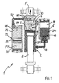
- eine erste nicht erfindungsgemäße Ausführungsform einer Federungs- und Dämpfungseinrichtung,
- Fig. 2
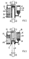
- eine verkleinerte Ansicht der Einrichtung gemäß
Fig. 1 in einem eingefederten Zustand, - Fig. 3
- eine Ansicht analog zu
Fig. 2 im ausgefederten Zustand, - Fig. 4
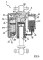
- eine zweite, ebenfalls nicht erfindungsgemäße Ausführungsform der Einrichtung in einer Darstellung analog zu
Fig. 1 , - Fig. 5 und 6
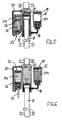
- Darstellungen der Ausführung gemäß
Fig. 4 analog zuFig. 2 und 3 , - Fig. 7 bis 9
- Darstellungen analog zu
Fig. 1 bis 3 bzw.Fig. 4 bis 6 einer erfindungsgemäßen Ausführungsform, - Fig. 10
- eine weitere Ausführungsform der Erfindung und
- Fig. 11
- eine Ausgestaltung am Beispiel der Ausführung gemäß
Fig. 4 bis 6 . - In den verschiedenen Figuren der Zeichnung sind gleiche bzw. sich funktionell entsprechende Teile und Komponenten stets mit den gleichen Bezugszeichen versehen. Daher gilt jede Beschreibung eines Teils, die auf eine oder mehrere bestimmte Zeichnungsfiguren Bezug nimmt, analog auch bezüglich der anderen Zeichnungsfiguren, in denen das Teil mit dem entsprechenden Bezugszeichen ebenfalls zu erkennen ist
- Eine Federungs- und Dämpfungseinrichtung 1 besteht in allen Ausführungsbeispielen aus (mindestens) einem Federzylinder 2, der zur direkten Anordnung zwischen einem Fahrzeugrad bzw. einem Rad-Schwingentragarm und einem Fahrzeugrahmen (beides nicht dargestellt) vorgesehen ist. Der Federzylinder 2 besteht teleskapartig aus einem Zylinder 4 und einem darin linear verschiebbar geführten Kolben 6 mit einer Kolbenstange 8, die umfangsgemäß abgedichtet aus dem Zylinder 4 herausgeführt ist.
- Zur Erzeugung einer lasttragenden Tragfederkraft F wirkt der Kolben 6 erfindungsgemäß unmittelbar (
Fig. 7 bis 10 ) gegen ein elastisch kompressibles Federmedium FM. Zum Dämpfen von Federungsbewegungen ist ein separater, von dem Federmedium FM unabhängiger Kreislauf eines hydraulischen Dämpfungsmediums DM vorgesehen. - Der Kolben 6 liegt Ober mindestens eine ringförmige Kolbendichtung an der Innenfläche des Zylinders 4 an. Dadurch trennt der Kolben 6 innerhalb des Zylinders 4 zwei Arbeitsräume voneinander, wobei ein erster Arbeitsraum 10 dem Federmedium FM und ein zweiter Arbeitsraum 12 dem Dämpfungsmedium DM zugeordnet sind. Folglich trennt der Kolben 6 erfindungsgemäß auch einen "Federkreislauf" von einem "Dämpfungskreislauf.
- Bei den dargestellten Ausführungsbeispielen ist der Federzylinder 2 als Druckzylinder ausgeführt. Dies bedeutet, dass er praktisch als Druckfeder wirkt, um die jeweilige Last abzustützten. Dazu ist der dem Federmedium FM zugeordnete erste Arbeitsraum 10 als zylindrischer Raum auf der der Kolbenstange 8 gegenüberliegenden Seite des Kolbens 6 gebildet. Der zweite Arbeitsraum 12 umschließt ringförmig bzw. hohlzylindrisch die Kolbenstange 8. Da der zweite Arbeitsraum 12 erfindungsgemäß dem Dämpfungsmedium DM zugeordnet ist, wirkt bei dieser Ausgestaltung die Kolbenstange 8 vorteilhafterweise als Kühlelement zur Kühlung des sich bei Dämpfung bzw. Drosselung erwärmenden Dämpfungsmediums DM.
- Der zweite Arbeitsraum 12 ist über eine Dämpfungsventilanordnung 14 mit einem Hydraulikbehälter 16 verbunden. Bevorzugt ist die Dämpfungsventilanordnung 14 in einem Einlassbereich des Hydraulikbehäfters 16 integriert angeordnet. Der Hydraulikbehälter 16 ist bevorzugt als gesondertes Bauteil extem, getrennt von dem Federzylinder 2 angeordnet und über eine Leitung 18 mit dem zweiten Arbeitsraum 12 des Federzylinders 2 verbunden. Indem die Dämpfungsventilanordnung 14 integriert im EinlassbereiCh des Hydraulikbehälters 16 angeordnet ist, entsteht eine dämpfungs- bzw. drosselbedingte Erwärmung des Dämpfungsmediums DM vorteilhafterweise in einem entfernt von dem Federzylinder 2 und damit auch entfernt von dem Federmedium FM liegenden Bereich. Zudem wird durch den externen Hydraulikbehälter 16 vorteilhafterweise auch eine zusätzliche Kühlwirkung zur Kühlung des Dämpfungsmediums DM erreicht, indem Wärme Ober eine große Außenfläche (Kühlfläche) an die Umgebung abgegeben wird. Zwar kann ein Wärrneanteil über das Dämpfungsmedium DM auch in den zweiten Arbeitsraum 12 gelangen, jedoch wirkt, wie oben bereits angedeutet wurde, die Kolbenstange 8 als Kühlelement, indem sie von dem Dämpfungsmedium DM umschlossen ist und dadurch dessen Wärme nach außen transportiert. Dies ist besonders effektiv, weil sich die Kolbenstange bei den Federungsbewegungen ja teilweise auch nach außen aus dem Zylinder 4 bewegt und jegliche Wärme dort an die Umgebung abgeben kann. Es kann davon gesprochen werden, dass die Kolbenstange 8 eine Art .Wärmepumpe" bildet. Zusätzlich wird Wärme auch über die Außenfläche des Zylinders 4 an die Umgebung abgegeben. Es werden somit durch die erfindungsgemäße Anordnung insgesamt sehr große Kühlflächen zur effektiven Kühlung des Dämpfungsmediums DM genutzt, so dass ein Wärmeübergang über den Kolben 6 auf das Federmedium vorteilhafterweise allenfalls minimal ist.
- Es kommt noch hinzu, dass bei den bevorzugten Ausführungen eine Dämpfung nur im halben Federungszyklus erfolgt, und zwar durch eine entsprechende Ausgestaltung der Dämpfungsventilanordnung 14 (mit Drossel- und Rückschlagventilen) nur beim Ausfedern, während Einfederungsbewegungen nahezu ungedämpft sind, so dass Wärme eigentlich nur beim Ausfedern entsteht. Der Einfederungshub kann zur Kühlung genutzt werden. Beim Einfedem kann auf eine hydraulische Dämpfung verzichtet werden, weil dann das Federmedium FM durch eine ansteigende Federkennlinie quasi dämpfend wirkt.
- Der Hydraulikbehälter 16 wird vorzugsweise in einem Fahrzeug so angeordnet, dass er etwa parallel neben dem Federzylinder 2 angeordnet ist, und zwar so, dass das Dämpfungsmedium DM schwerkraftbedingt sich im unteren Bereich befindet In einem Raum 19 oberhalb des Dämpfungsmediums DM kann Luft angeordnet sein. Erfindungsgemäß ist vorgesehen, diesen Raum 19 oberhalb des Dämpfungsmediums DM unter einen bestimmten Vorspanndruck von z. B, 3 bis 5 bar zu setzen, um beim Einfedem den Fluss in den zweiten Arbeitsraum hinein zu unterstützen (zu beschleunigen).
- In den nicht erfindungsgemäßen Ausführungsformen gemäß
Fig. 1 bis 6 und auch gemäßFig. 11 ist der erste Arbeitsraum 1β über eine Leitung 20 mit einem das elastisch kompressible Federmedium FM enthaltenden Federspeicher 22 verbunden. Dieser Federspeicher 22 ist bevorzugt als hydropneumatischer Kolbenspeicher mit einem in einem Speicherzylinder 24 frei (schwimmend) beweglichen Trennkolben 26 ausgebildet. Der Trennkolben 26 liegt über mindestens einen Dichtring dichtend an der Innenfläche des Speicherzylinders 24 an und trennt dadurch einen hydraulisch über die Leitung 20 mit dem ersten Arbeitsraum 10 verbundenen Speicherraum 28 von einer das Federmedium FM enthaltenden Federkammer 30, wobei der erste Arbeitsraum 10 und der Speicherraum 28 hierbei vollständig mit einem Hydraulikmedium HM gefüllt sind. Somit wirkt hierbei der Kolben 6 des Federzylinders 2 mittelbar über das Hydraulikmedium HM und über den Trennkolben 26 gegen das Federmedium FM innerhalb der Federkammer 30. - Beim Einfedem wird von dem Kolben 6 ein bestimmtes Volumen des Hydraulikmediums HM in den Speicherraum 28 verdrängt, wodurch der Trennkolben 26 gegen das Federmedium FM in Richtung der Federkammer 30 verschoben wird. Durch die daraus resultierende Volumenverminderung erhöht sich der Druck des Federmediums FM und damit auch die Tragkraft F.
- Bei der Ausführung gemäß
Fig. 1 bis 3 ist der Trennkolben 26 als Trennwand vollständig innerhalb des Speicherzylinders 24 angeordnet. Dadurch muss er eine relativ große axiale Länge aufweisen, um zu vermeiden, dass er innerhalb des Speicherzylinders 24 kippt und dadurch klemmt (so genannter "Schubladeneffekt"). - Bei der Ausführung gemäß
Fig. 4 bis 6 ist demgegenüber vorgesehen, dass der Trennkolben 26 eine sich axial durch den Speicherraum 28 hindurch erstreckende und abgedichtet aus dem Speicherzylinder 24 nach außen geführte Trennkolbenstange 32 aufweist. Durch die Trennkolbenstange 32 wird einerseits eine zusätzliche Führung des Trennkolbens 26 gegen Verkippen erreicht, so dass der Trennkolben 26 selbst mit kürzerer axialer Länge ausgeführt sein kann. Dadurch kann insgesamt Baulänge des Federspeichers 22 eingespart werden. Andererseits wirkt der Federspeicher 22 in dieser Ausführung aufgrund der Trennkolbenstange 32 auch als Druckwandler derart, dass der Druck des Federmediums FM stets kleiner als der Druck des Hydraulikmediums HM ist Dies liegt daran, dass die jeweils mit Druck beaufschlagten gegenüberliegenden Flächen des Trennkolbens 26 unterschiedlich groß sind. Auf der Seite der Federkammer 30 wird eine größere Oberfläche von dem Federmedium FM beaufschlagt, so dass für ein statisches Gleichgewicht des Trennkolbens 26 ein geringerer Druck des Federmediums FM ausreicht. Mit anderen Worten muss der gegenüberliegende Druck des Hydraulikmediums HM wegen der die Trennkolbenstange 32 umschließenden kleineren Ringfläche des Trennkolbens 26 größer sein, um den Trennkolben 26 im Gleichgewicht zu halten. - Wie weiter in
Fig. 4 bis 6 und auch inFig. 11 dargestellt ist, ist der Federspeicher 22 parallel neben dem Federzylinder 2 angeordnet, und zwar insbesondere in einer Ausrichtung, in der die Kolbenstange 8 des Federzylinders 2 und die Trennkolbenstange 32 des Federspeichers 22 mit jeweils gleichläufigen Bewegungsrichtungen in die gleiche Richtung weisen. Wie sich aus den Darstellungen inFig. 5 und 6 ergibt, bewegt sich die Trennkolbenstange 32 aus dem Federspeicher 22 heraus, wenn auch der Federzylinder 2 ausfedert, d. h. wenn die Kolbenstange 8 sich ebenfalls aus dem Zylinder 4 herausbewegt. Hierdurch werden Kollisionsprobleme mit anderen Fahrzeug-Bauteilen bei den Fahrzeug-Federungsbewegungen vermieden. - Bei der erfindungsgemäßen Ausführung gemäß
Fig. 7 bis 9 ist der erste Arbeitsraum 10 des Federzylinders 2 direkt mit dem elastisch kompressiblen Federmedium FM gefüllt, so dass der Kolben 6 unmittelbar gegen das Federmedium FM wirkt. Dadurch erübrigt sich ein zusätzlicher, externer Federspeicher 22. Daraus resultiert eine besonders kompakte und leichtgewichtige Bauform der Federungs- und Dämpfungseinrichtung 1, Da sich das kompressible Federmedium FM aber nicht beliebig, und insbesondere nicht bis auf ein Nullvolumen komprimieren lässt, ist bei dieser Ausführung ein Mindest-Restvolumen durch einen Hohlraum 34 innerhalb des Kolbens 6 und der Kolbenstange 8 gebildet. - Alternativ oder aber zusätzlich zu dem Hohlraum 34 kann gemäß
Fig. 10 ein externer Zusatzbehälter 36 über eine Leitung 38 mit dem ersten Arbeitsraum 10 verbunden sein. Auch bei dieser Ausführung ist erfindungsgemäß direkt in dem ersten Arbeitsraum 10 das elastische Federmedium FM angeordnet. - Als kompressibles Federmedium FM kann insbesondere ein gasförmiges Medium verwendet werden, beispielsweise Stickstoff. Alternativ ist auch ein beliebiges anderes, beispielsweise liquides oder pastöses (hochviskoses) Medium geeignet. Als Dämpfungsmedium DM und/oder Hydraulikmedium HM kann ein übliches, insbesondere niederviskoses Hydrauliköl verwendet werden.
- Wie sich noch aus
Fig. 1 bis 6 ergibt, ist der Federzylinder 2 mit einer Einrichtung zur hydraulischen Endlagendämpfung ausgestattet. Diese Endlagendämpfung ist inFig. 1 und4 jeweils mit der Bezugsziffer 40 bezeichnet. Diese Endlagendämpfung 40 wirkt bevorzugt in Einfederungsrichtung derart, dass eine Abbremsung der Federungsbewegungen jeweils gegen Ende des Einfederungshubes vor Erreichen eines mechanischen Endanschlages gewährleistet ist. Konkret handelt es sich um eine wegabhängige hydraulische Drasseleinrichtung mit einem teleskopartig in den Kolben 6 verschiebbaren Stößel 42, der einen axialen Strömungskanal aufweist, in den mehrere radiale, über die Länge verteilt angeordnete Queröffnungen münden. Durch das Eintauchen des Stößels 42 in den Kolben 6 werden bei Bewegung bis in die Endanschlagstellung die Queröffnungen sukzessive nacheinander verschlossen, Dadurch wird der Strömungswiderstand sukzessive vergrößert, well das Hydraulikmedium HM bei mechanischer Anlage des Stößels 42 im Bereich einer Ausströmöffnung des Zylinders 4 (siehe hierzu die Stellungen inFig. 2 und5 ) nur über die Queröffnungen und den axialen Kanal des Stößels 42 ausströmen kann. Dadurch wird die jeweilige Bewegung sanft abgebremst; ein harter Endanschlag wird vorteilhafterweise vermieden. - In
Fig. 11 ist schließlich noch eine hydraulische Nivelliereinrichtung 44 veranschaulicht, die derart ausgebildet ist, dass ein statisches Fahrzeugniveau durch Zuführen oder Ablassen von Hydraulikmedium HM in den oder aus dem Federkreislauf veränderbar ist. Dazu besteht die Nivelliereinrichtung 44 aus einem Schaltventil 46, einem Tank 48 und einer Pumpe 50. Das Schaltventil 46 ist als 3/3-Wegeventil ausgeführt und in der dargestellten Stellung geschlossen. In einer ersten Schaltstellung lässt sich die Pumpe 50 mit dem Federungskreislauf verbinden, um Hydraulikmedium zuzuführen und dadurch das Niveau anzuheben. In einer zweiten Schaltstellung wird der Federungskreislauf mit dem Tank 48 verbunden, um zur Niveau-Absenkung Hydraulikmedium abzulassen.
Claims (7)
- Federungs- und Dämpfungseinrichtung (1) zur lasttragenden und federnden Rad-Abstützung und zum Dämpfen von Federungsbewegungen in einem Kraftfahrzeug, bestehend aus mindestens einem Federzylinder (2) mit einem in einem Zylinder (4) relativbeweglich geführten Kolben (6), der zur Erzeugung einer lasttragenden Tragfederkraft (F) gegen ein elastisch kompressibles Federmedium (FM) wirkt, wobei der Kolben (6) einseitig eine umfangsgemäß abgedichtet aus dem Zylinder (4) nach außen geführte Kalbenstange (8) aufweist, und wobei der Kolben (6) innerhalb des Zylinders (4) zwei Arbeitsräume (10, 12) voneinander trennt, und zwar einen als zylindrischer Raum auf der der Kolbenstange (8) gegenüberliegenden Seite angeordneten ersten Arbeitsraum (10) von einem als Ringraum die Kolbenstange (8) hohlzylindrisch umschließenden zweiten Arbeitsraum (12),
dadurch gekennzeichnet, dass zum Dämpfen ein separater, von dem Federmedium (FM) unabhängiger Kreislauf eines hydraulischen Dämpfungsmediums (DM) vorgesehen ist, indem der zylindrische erste Arbeitsraum (10) dem Federmedium (FM) und der hohlzylindrische zweite Arbeitsraum (12) dem Dämpfungsmedium (DM) zugeordnet sind, wobei der zweite Arbeitsraum (12) mit dem hydraulischen Dämpfungsmedium (DM) gefüllt und über eine Dämpfungsventilanordnung (14) mit einem Hydraulikbehälter (16) verbunden ist, in dem das Dämpfungsmedium (DM) unter einem bestimmten Vorspanndruck steht, und wobei der erste Arbeitsraum (10) mit dem elastisch kompressiblen Federmedium (FM) gefüllt ist, so dass der Kolben (6) unmittelbar gegen das Federmedium (FM) wirkt. - Federungs- und Dämpfungseinrichtung nach Anspruch 1,
dadurch gekennzeichnet, dass der Vorspanndruck in dem Hydraulikbehälter (16) im Bereich von 3 bis 5 bar liegt. - Federungs- und Dämpfungseinrichtung nach Anspruch 1 oder 2,
dadurch gekennzeichnet, dass der erste Arbeitsraum (10) über eine Leitung (3B) mit einem das elastisch kompressible Federmedium (FM) enthaltenden Zusatzbehälter (36) verbunden ist. - Federungs- und Dämpfungseinrichtung nach einem der Ansprüche 1 bis 3,
dadurch gekennzeichnet, dass der Kolben (6) einen Hohlraum (34) zur Bildung eines Mindest-Restvolumens für das Federmedium (FM) aufweist. - Federungs- und Dämpfungseinrichtung nach einem der Ansprüche 1 bis 4,
dadurch gekennzeichnet, dass als kompressibles Federmedium (FM) ein gasförmiges und/oder liquides Medium vorgesehen ist. - Federungs- und Dämpfungseinrichtung nach einem der Ansprüche 1 bis 5,
dadurch gekennzeichnet, dass die Dämpfungsventilanordnung (14) in einem Einlassbereich des Hydraulikbehäkers (16) angeordnet ist. - Federungs- und Dämpfungseinrichtung nach einem der Ansprüche 1 bis 6,
dadurch gekennzeichnet, dass der Hydraulikbehälter (16) über eine Leitung (18) mit dem zweiten Arbeitsraum (12) des Federzylinders (2) verbunden und insbesondere parallel neben dem Federzylinder (2) angeordnet ist, und zwar bevorzugt so, dass sich das Dämpfungsmedium (DM) schwerkraftbedingt im unteren Bereich befindet.
Applications Claiming Priority (2)
| Application Number | Priority Date | Filing Date | Title |
|---|---|---|---|
| DE202004005623U DE202004005623U1 (de) | 2004-04-08 | 2004-04-08 | Federungs- und Dämpfungseinrichtung für Kraftfahrzeuge |
| EP05102596A EP1584502B1 (de) | 2004-04-08 | 2005-04-01 | Federungs- und Dämpfungseinrichtung für Kraftfahrzeuge |
Related Parent Applications (2)
| Application Number | Title | Priority Date | Filing Date |
|---|---|---|---|
| EP05102596.3 Division | 2005-04-01 | ||
| EP05102596A Division EP1584502B1 (de) | 2004-04-08 | 2005-04-01 | Federungs- und Dämpfungseinrichtung für Kraftfahrzeuge |
Publications (2)
| Publication Number | Publication Date |
|---|---|
| EP2116403A1 EP2116403A1 (de) | 2009-11-11 |
| EP2116403B1 true EP2116403B1 (de) | 2012-01-18 |
Family
ID=34854257
Family Applications (2)
| Application Number | Title | Priority Date | Filing Date |
|---|---|---|---|
| EP05102596A Not-in-force EP1584502B1 (de) | 2004-04-08 | 2005-04-01 | Federungs- und Dämpfungseinrichtung für Kraftfahrzeuge |
| EP09169057A Not-in-force EP2116403B1 (de) | 2004-04-08 | 2005-04-01 | Federungs- und Dämpfungseinrichtung für Kraftfahrzeuge |
Family Applications Before (1)
| Application Number | Title | Priority Date | Filing Date |
|---|---|---|---|
| EP05102596A Not-in-force EP1584502B1 (de) | 2004-04-08 | 2005-04-01 | Federungs- und Dämpfungseinrichtung für Kraftfahrzeuge |
Country Status (4)
| Country | Link |
|---|---|
| EP (2) | EP1584502B1 (de) |
| AT (2) | ATE541727T1 (de) |
| DE (2) | DE202004005623U1 (de) |
| ES (1) | ES2332370T3 (de) |
Families Citing this family (5)
| Publication number | Priority date | Publication date | Assignee | Title |
|---|---|---|---|---|
| EP2186662B1 (de) | 2008-11-18 | 2013-03-27 | HEMSCHEIDT FAHRWERKTECHNIK GmbH & Co. KG | Dämpfungssystem für Fahrzeuge |
| DE202008018221U1 (de) | 2008-12-12 | 2012-02-27 | Hemscheidt Fahrwerktechnik Gmbh & Co. Kg | Dämpfungseinrichtung für Fahrzeuge |
| ATE555929T1 (de) | 2008-12-12 | 2012-05-15 | Hemscheidt Fahrwerktech Gmbh | Dämpfungseinrichtung für fahrzeuge |
| ATE550569T1 (de) * | 2009-08-19 | 2012-04-15 | Hemscheidt Fahrwerktech Gmbh | Hydropneumatischer kolbenspeicher |
| CN109268428B (zh) * | 2018-11-02 | 2020-05-26 | 常州大学 | 一种基于非线性刚度对称隔振的流体隔振器 |
Family Cites Families (8)
| Publication number | Priority date | Publication date | Assignee | Title |
|---|---|---|---|---|
| SE347046B (de) * | 1969-11-07 | 1972-07-24 | Monsun Tison Ab | |
| JPS6264603A (ja) * | 1985-09-15 | 1987-03-23 | Showa Seisakusho:Kk | 車輪懸架装置用油圧緩衝器における底突き防止装置 |
| DE3902743C1 (en) * | 1989-01-31 | 1990-07-26 | Daimler-Benz Aktiengesellschaft, 7000 Stuttgart, De | Active wheel or axle support |
| EP0425885B1 (de) * | 1989-10-28 | 1994-07-20 | HEMSCHEIDT FAHRWERKTECHNIK GmbH & Co. | Hydropneumatisches Federungssystem |
| DE4127801A1 (de) * | 1991-08-22 | 1993-02-25 | Hemscheidt Maschf Hermann | Hydropneumatisches federungssystem fuer eine fahrzeug-liftachse |
| US5413030A (en) * | 1994-02-17 | 1995-05-09 | Caterpillar Inc. | Self-energizing snubber for a hydraulic motor |
| DE60219708T2 (de) * | 2001-02-09 | 2007-12-27 | Technology Investments Ltd. | Hydropneumatisches Aufhängungssystem |
| DE20209120U1 (de) | 2002-06-12 | 2003-10-16 | Hemscheidt Fahrwerktech Gmbh | Federungseinrichtung für Kraftfahrzeuge |
-
2004
- 2004-04-08 DE DE202004005623U patent/DE202004005623U1/de not_active Expired - Lifetime
-
2005
- 2005-04-01 DE DE502005008465T patent/DE502005008465D1/de active Active
- 2005-04-01 ES ES05102596T patent/ES2332370T3/es active Active
- 2005-04-01 AT AT09169057T patent/ATE541727T1/de active
- 2005-04-01 AT AT05102596T patent/ATE448099T1/de active
- 2005-04-01 EP EP05102596A patent/EP1584502B1/de not_active Not-in-force
- 2005-04-01 EP EP09169057A patent/EP2116403B1/de not_active Not-in-force
Also Published As
| Publication number | Publication date |
|---|---|
| ES2332370T3 (es) | 2010-02-03 |
| EP1584502A1 (de) | 2005-10-12 |
| ATE448099T1 (de) | 2009-11-15 |
| DE502005008465D1 (de) | 2009-12-24 |
| EP2116403A1 (de) | 2009-11-11 |
| DE202004005623U1 (de) | 2005-08-11 |
| EP1584502B1 (de) | 2009-11-11 |
| ATE541727T1 (de) | 2012-02-15 |
Similar Documents
| Publication | Publication Date | Title |
|---|---|---|
| EP2196337B1 (de) | Dämpfungseinrichtung für Fahrzeuge | |
| DE112013004595B4 (de) | Aufhängungsvorrichtung | |
| EP1775495A2 (de) | Schwingungsdämpfer mit verstellbarer Dämpfkraft | |
| DE102007015888A1 (de) | Federanordnung mit verstellbarer Federrate und Federbein | |
| WO2015165910A2 (de) | Schwingungsdämpfer eines fahrzeug-rads | |
| EP2241460A1 (de) | Federungseinrichtung für Kraftfahrzeuge | |
| DE102015115400B4 (de) | Luftfeder | |
| EP2930270B1 (de) | Dämpfervorrichtung | |
| DE4116399C2 (de) | Kolbenzylindereinheit insbesondere zur Verwendung als Federbein in Fahrzeug-Federungssystemen | |
| DE102006008608B4 (de) | Radaufhängung | |
| DE102006025826A1 (de) | Selbstpumpendes hydropneumatisches Federbein | |
| EP2116403B1 (de) | Federungs- und Dämpfungseinrichtung für Kraftfahrzeuge | |
| DE2016192A1 (de) | Hochdruckgasfederungssystem mit Niveauregelung, insbesondere für Kraftfahrzeuge | |
| EP3746676B1 (de) | Schwingungsdämpfer für ein fahrzeug | |
| DE19829765A1 (de) | Kolben-Zylinderaggregat mit einem hydraulisch-mechanischen Anschlag | |
| EP1657470B1 (de) | Hydropneumatisches Federelement für Kraftfahrzeuge, insbesondere Kettenfahrzeuge | |
| EP2404078B1 (de) | Dämpfungssystem zur anschlagsdämpfung | |
| EP2668417B1 (de) | Federungseinrichtung für fahrzeuge | |
| DE3935608A1 (de) | Kolbenzylindereinheit | |
| DE102020130940A1 (de) | Hydraulischer Stoßdämpfer | |
| DE102016201649B4 (de) | Selbstpumpendes hydropneumatisches Federbein | |
| EP3329142B1 (de) | Hydraulischer einrohr-teleskop-schwingungsdämpfer | |
| DE102022002547B4 (de) | Ventilbaugruppe und Feder-Dämpfer-System mit Ventilbaugruppe | |
| EP3576965A1 (de) | Federbein mit veränderlicher federrate | |
| EP2186662B1 (de) | Dämpfungssystem für Fahrzeuge |
Legal Events
| Date | Code | Title | Description |
|---|---|---|---|
| PUAI | Public reference made under article 153(3) epc to a published international application that has entered the european phase |
Free format text: ORIGINAL CODE: 0009012 |
|
| 17P | Request for examination filed |
Effective date: 20090831 |
|
| AC | Divisional application: reference to earlier application |
Ref document number: 1584502 Country of ref document: EP Kind code of ref document: P |
|
| AK | Designated contracting states |
Kind code of ref document: A1 Designated state(s): AT BE BG CH CY CZ DE DK EE ES FI FR GB GR HU IE IS IT LI LT LU MC NL PL PT RO SE SI SK TR |
|
| 17Q | First examination report despatched |
Effective date: 20100519 |
|
| GRAP | Despatch of communication of intention to grant a patent |
Free format text: ORIGINAL CODE: EPIDOSNIGR1 |
|
| GRAS | Grant fee paid |
Free format text: ORIGINAL CODE: EPIDOSNIGR3 |
|
| GRAA | (expected) grant |
Free format text: ORIGINAL CODE: 0009210 |
|
| AC | Divisional application: reference to earlier application |
Ref document number: 1584502 Country of ref document: EP Kind code of ref document: P |
|
| AK | Designated contracting states |
Kind code of ref document: B1 Designated state(s): AT BE BG CH CY CZ DE DK EE ES FI FR GB GR HU IE IS IT LI LT LU MC NL PL PT RO SE SI SK TR |
|
| REG | Reference to a national code |
Ref country code: GB Ref legal event code: FG4D Free format text: NOT ENGLISH |
|
| REG | Reference to a national code |
Ref country code: CH Ref legal event code: NV Representative=s name: BRAUNPAT BRAUN EDER AG Ref country code: CH Ref legal event code: EP |
|
| REG | Reference to a national code |
Ref country code: AT Ref legal event code: REF Ref document number: 541727 Country of ref document: AT Kind code of ref document: T Effective date: 20120215 Ref country code: IE Ref legal event code: FG4D Free format text: LANGUAGE OF EP DOCUMENT: GERMAN |
|
| REG | Reference to a national code |
Ref country code: DE Ref legal event code: R096 Ref document number: 502005012379 Country of ref document: DE Effective date: 20120322 |
|
| REG | Reference to a national code |
Ref country code: NL Ref legal event code: VDEP Effective date: 20120118 |
|
| LTIE | Lt: invalidation of european patent or patent extension |
Effective date: 20120118 |
|
| PGFP | Annual fee paid to national office [announced via postgrant information from national office to epo] |
Ref country code: GB Payment date: 20120328 Year of fee payment: 8 |
|
| PG25 | Lapsed in a contracting state [announced via postgrant information from national office to epo] |
Ref country code: NL Free format text: LAPSE BECAUSE OF FAILURE TO SUBMIT A TRANSLATION OF THE DESCRIPTION OR TO PAY THE FEE WITHIN THE PRESCRIBED TIME-LIMIT Effective date: 20120118 Ref country code: BG Free format text: LAPSE BECAUSE OF FAILURE TO SUBMIT A TRANSLATION OF THE DESCRIPTION OR TO PAY THE FEE WITHIN THE PRESCRIBED TIME-LIMIT Effective date: 20120418 Ref country code: IS Free format text: LAPSE BECAUSE OF FAILURE TO SUBMIT A TRANSLATION OF THE DESCRIPTION OR TO PAY THE FEE WITHIN THE PRESCRIBED TIME-LIMIT Effective date: 20120518 Ref country code: LT Free format text: LAPSE BECAUSE OF FAILURE TO SUBMIT A TRANSLATION OF THE DESCRIPTION OR TO PAY THE FEE WITHIN THE PRESCRIBED TIME-LIMIT Effective date: 20120118 |
|
| PGFP | Annual fee paid to national office [announced via postgrant information from national office to epo] |
Ref country code: CH Payment date: 20120412 Year of fee payment: 8 Ref country code: DE Payment date: 20120627 Year of fee payment: 8 |
|
| REG | Reference to a national code |
Ref country code: IE Ref legal event code: FD4D |
|
| PG25 | Lapsed in a contracting state [announced via postgrant information from national office to epo] |
Ref country code: GR Free format text: LAPSE BECAUSE OF FAILURE TO SUBMIT A TRANSLATION OF THE DESCRIPTION OR TO PAY THE FEE WITHIN THE PRESCRIBED TIME-LIMIT Effective date: 20120419 Ref country code: PL Free format text: LAPSE BECAUSE OF FAILURE TO SUBMIT A TRANSLATION OF THE DESCRIPTION OR TO PAY THE FEE WITHIN THE PRESCRIBED TIME-LIMIT Effective date: 20120118 Ref country code: PT Free format text: LAPSE BECAUSE OF FAILURE TO SUBMIT A TRANSLATION OF THE DESCRIPTION OR TO PAY THE FEE WITHIN THE PRESCRIBED TIME-LIMIT Effective date: 20120518 Ref country code: FI Free format text: LAPSE BECAUSE OF FAILURE TO SUBMIT A TRANSLATION OF THE DESCRIPTION OR TO PAY THE FEE WITHIN THE PRESCRIBED TIME-LIMIT Effective date: 20120118 |
|
| PGFP | Annual fee paid to national office [announced via postgrant information from national office to epo] |
Ref country code: FR Payment date: 20120504 Year of fee payment: 8 |
|
| PG25 | Lapsed in a contracting state [announced via postgrant information from national office to epo] |
Ref country code: CY Free format text: LAPSE BECAUSE OF FAILURE TO SUBMIT A TRANSLATION OF THE DESCRIPTION OR TO PAY THE FEE WITHIN THE PRESCRIBED TIME-LIMIT Effective date: 20120118 |
|
| BERE | Be: lapsed |
Owner name: HEMSCHEIDT FAHRWERKTECHNIK G.M.B.H. & CO. KG Effective date: 20120430 |
|
| PG25 | Lapsed in a contracting state [announced via postgrant information from national office to epo] |
Ref country code: EE Free format text: LAPSE BECAUSE OF FAILURE TO SUBMIT A TRANSLATION OF THE DESCRIPTION OR TO PAY THE FEE WITHIN THE PRESCRIBED TIME-LIMIT Effective date: 20120118 Ref country code: IE Free format text: LAPSE BECAUSE OF FAILURE TO SUBMIT A TRANSLATION OF THE DESCRIPTION OR TO PAY THE FEE WITHIN THE PRESCRIBED TIME-LIMIT Effective date: 20120118 Ref country code: CZ Free format text: LAPSE BECAUSE OF FAILURE TO SUBMIT A TRANSLATION OF THE DESCRIPTION OR TO PAY THE FEE WITHIN THE PRESCRIBED TIME-LIMIT Effective date: 20120118 Ref country code: SI Free format text: LAPSE BECAUSE OF FAILURE TO SUBMIT A TRANSLATION OF THE DESCRIPTION OR TO PAY THE FEE WITHIN THE PRESCRIBED TIME-LIMIT Effective date: 20120118 Ref country code: SE Free format text: LAPSE BECAUSE OF FAILURE TO SUBMIT A TRANSLATION OF THE DESCRIPTION OR TO PAY THE FEE WITHIN THE PRESCRIBED TIME-LIMIT Effective date: 20120118 Ref country code: RO Free format text: LAPSE BECAUSE OF FAILURE TO SUBMIT A TRANSLATION OF THE DESCRIPTION OR TO PAY THE FEE WITHIN THE PRESCRIBED TIME-LIMIT Effective date: 20120118 Ref country code: DK Free format text: LAPSE BECAUSE OF FAILURE TO SUBMIT A TRANSLATION OF THE DESCRIPTION OR TO PAY THE FEE WITHIN THE PRESCRIBED TIME-LIMIT Effective date: 20120118 |
|
| PLBE | No opposition filed within time limit |
Free format text: ORIGINAL CODE: 0009261 |
|
| STAA | Information on the status of an ep patent application or granted ep patent |
Free format text: STATUS: NO OPPOSITION FILED WITHIN TIME LIMIT |
|
| PG25 | Lapsed in a contracting state [announced via postgrant information from national office to epo] |
Ref country code: IT Free format text: LAPSE BECAUSE OF FAILURE TO SUBMIT A TRANSLATION OF THE DESCRIPTION OR TO PAY THE FEE WITHIN THE PRESCRIBED TIME-LIMIT Effective date: 20120118 Ref country code: MC Free format text: LAPSE BECAUSE OF NON-PAYMENT OF DUE FEES Effective date: 20120430 Ref country code: SK Free format text: LAPSE BECAUSE OF FAILURE TO SUBMIT A TRANSLATION OF THE DESCRIPTION OR TO PAY THE FEE WITHIN THE PRESCRIBED TIME-LIMIT Effective date: 20120118 |
|
| 26N | No opposition filed |
Effective date: 20121019 |
|
| PG25 | Lapsed in a contracting state [announced via postgrant information from national office to epo] |
Ref country code: BE Free format text: LAPSE BECAUSE OF NON-PAYMENT OF DUE FEES Effective date: 20120430 |
|
| REG | Reference to a national code |
Ref country code: DE Ref legal event code: R097 Ref document number: 502005012379 Country of ref document: DE Effective date: 20121019 |
|
| PGFP | Annual fee paid to national office [announced via postgrant information from national office to epo] |
Ref country code: AT Payment date: 20120327 Year of fee payment: 8 |
|
| PG25 | Lapsed in a contracting state [announced via postgrant information from national office to epo] |
Ref country code: ES Free format text: LAPSE BECAUSE OF FAILURE TO SUBMIT A TRANSLATION OF THE DESCRIPTION OR TO PAY THE FEE WITHIN THE PRESCRIBED TIME-LIMIT Effective date: 20120429 |
|
| REG | Reference to a national code |
Ref country code: CH Ref legal event code: PL |
|
| REG | Reference to a national code |
Ref country code: AT Ref legal event code: MM01 Ref document number: 541727 Country of ref document: AT Kind code of ref document: T Effective date: 20130430 |
|
| GBPC | Gb: european patent ceased through non-payment of renewal fee |
Effective date: 20130401 |
|
| PG25 | Lapsed in a contracting state [announced via postgrant information from national office to epo] |
Ref country code: LI Free format text: LAPSE BECAUSE OF NON-PAYMENT OF DUE FEES Effective date: 20130430 Ref country code: CH Free format text: LAPSE BECAUSE OF NON-PAYMENT OF DUE FEES Effective date: 20130430 Ref country code: AT Free format text: LAPSE BECAUSE OF NON-PAYMENT OF DUE FEES Effective date: 20130430 Ref country code: GB Free format text: LAPSE BECAUSE OF NON-PAYMENT OF DUE FEES Effective date: 20130401 Ref country code: DE Free format text: LAPSE BECAUSE OF NON-PAYMENT OF DUE FEES Effective date: 20131101 |
|
| REG | Reference to a national code |
Ref country code: FR Ref legal event code: ST Effective date: 20131231 |
|
| REG | Reference to a national code |
Ref country code: DE Ref legal event code: R119 Ref document number: 502005012379 Country of ref document: DE Effective date: 20131101 |
|
| PG25 | Lapsed in a contracting state [announced via postgrant information from national office to epo] |
Ref country code: FR Free format text: LAPSE BECAUSE OF NON-PAYMENT OF DUE FEES Effective date: 20130430 |
|
| PG25 | Lapsed in a contracting state [announced via postgrant information from national office to epo] |
Ref country code: TR Free format text: LAPSE BECAUSE OF FAILURE TO SUBMIT A TRANSLATION OF THE DESCRIPTION OR TO PAY THE FEE WITHIN THE PRESCRIBED TIME-LIMIT Effective date: 20120118 |
|
| PG25 | Lapsed in a contracting state [announced via postgrant information from national office to epo] |
Ref country code: LU Free format text: LAPSE BECAUSE OF NON-PAYMENT OF DUE FEES Effective date: 20120401 |
|
| PG25 | Lapsed in a contracting state [announced via postgrant information from national office to epo] |
Ref country code: HU Free format text: LAPSE BECAUSE OF FAILURE TO SUBMIT A TRANSLATION OF THE DESCRIPTION OR TO PAY THE FEE WITHIN THE PRESCRIBED TIME-LIMIT Effective date: 20050401 |