EP2116318A2 - Hemming device - Google Patents
Hemming device Download PDFInfo
- Publication number
- EP2116318A2 EP2116318A2 EP09165982A EP09165982A EP2116318A2 EP 2116318 A2 EP2116318 A2 EP 2116318A2 EP 09165982 A EP09165982 A EP 09165982A EP 09165982 A EP09165982 A EP 09165982A EP 2116318 A2 EP2116318 A2 EP 2116318A2
- Authority
- EP
- European Patent Office
- Prior art keywords
- hemming
- roller
- work
- flange
- working
- Prior art date
- Legal status (The legal status is an assumption and is not a legal conclusion. Google has not performed a legal analysis and makes no representation as to the accuracy of the status listed.)
- Granted
Links
Images


Classifications
-
- B—PERFORMING OPERATIONS; TRANSPORTING
- B21—MECHANICAL METAL-WORKING WITHOUT ESSENTIALLY REMOVING MATERIAL; PUNCHING METAL
- B21D—WORKING OR PROCESSING OF SHEET METAL OR METAL TUBES, RODS OR PROFILES WITHOUT ESSENTIALLY REMOVING MATERIAL; PUNCHING METAL
- B21D39/00—Application of procedures in order to connect objects or parts, e.g. coating with sheet metal otherwise than by plating; Tube expanders
- B21D39/02—Application of procedures in order to connect objects or parts, e.g. coating with sheet metal otherwise than by plating; Tube expanders of sheet metal by folding, e.g. connecting edges of a sheet to form a cylinder
- B21D39/021—Application of procedures in order to connect objects or parts, e.g. coating with sheet metal otherwise than by plating; Tube expanders of sheet metal by folding, e.g. connecting edges of a sheet to form a cylinder for panels, e.g. vehicle doors
-
- B—PERFORMING OPERATIONS; TRANSPORTING
- B21—MECHANICAL METAL-WORKING WITHOUT ESSENTIALLY REMOVING MATERIAL; PUNCHING METAL
- B21D—WORKING OR PROCESSING OF SHEET METAL OR METAL TUBES, RODS OR PROFILES WITHOUT ESSENTIALLY REMOVING MATERIAL; PUNCHING METAL
- B21D19/00—Flanging or other edge treatment, e.g. of tubes
- B21D19/02—Flanging or other edge treatment, e.g. of tubes by continuously-acting tools moving along the edge
- B21D19/04—Flanging or other edge treatment, e.g. of tubes by continuously-acting tools moving along the edge shaped as rollers
- B21D19/043—Flanging or other edge treatment, e.g. of tubes by continuously-acting tools moving along the edge shaped as rollers for flanging edges of plates
-
- B—PERFORMING OPERATIONS; TRANSPORTING
- B21—MECHANICAL METAL-WORKING WITHOUT ESSENTIALLY REMOVING MATERIAL; PUNCHING METAL
- B21D—WORKING OR PROCESSING OF SHEET METAL OR METAL TUBES, RODS OR PROFILES WITHOUT ESSENTIALLY REMOVING MATERIAL; PUNCHING METAL
- B21D39/00—Application of procedures in order to connect objects or parts, e.g. coating with sheet metal otherwise than by plating; Tube expanders
- B21D39/02—Application of procedures in order to connect objects or parts, e.g. coating with sheet metal otherwise than by plating; Tube expanders of sheet metal by folding, e.g. connecting edges of a sheet to form a cylinder
- B21D39/021—Application of procedures in order to connect objects or parts, e.g. coating with sheet metal otherwise than by plating; Tube expanders of sheet metal by folding, e.g. connecting edges of a sheet to form a cylinder for panels, e.g. vehicle doors
- B21D39/023—Application of procedures in order to connect objects or parts, e.g. coating with sheet metal otherwise than by plating; Tube expanders of sheet metal by folding, e.g. connecting edges of a sheet to form a cylinder for panels, e.g. vehicle doors using rollers
-
- B—PERFORMING OPERATIONS; TRANSPORTING
- B25—HAND TOOLS; PORTABLE POWER-DRIVEN TOOLS; MANIPULATORS
- B25J—MANIPULATORS; CHAMBERS PROVIDED WITH MANIPULATION DEVICES
- B25J11/00—Manipulators not otherwise provided for
-
- Y—GENERAL TAGGING OF NEW TECHNOLOGICAL DEVELOPMENTS; GENERAL TAGGING OF CROSS-SECTIONAL TECHNOLOGIES SPANNING OVER SEVERAL SECTIONS OF THE IPC; TECHNICAL SUBJECTS COVERED BY FORMER USPC CROSS-REFERENCE ART COLLECTIONS [XRACs] AND DIGESTS
- Y10—TECHNICAL SUBJECTS COVERED BY FORMER USPC
- Y10T—TECHNICAL SUBJECTS COVERED BY FORMER US CLASSIFICATION
- Y10T29/00—Metal working
- Y10T29/49—Method of mechanical manufacture
- Y10T29/49826—Assembling or joining
- Y10T29/49893—Peripheral joining of opposed mirror image parts to form a hollow body
-
- Y—GENERAL TAGGING OF NEW TECHNOLOGICAL DEVELOPMENTS; GENERAL TAGGING OF CROSS-SECTIONAL TECHNOLOGIES SPANNING OVER SEVERAL SECTIONS OF THE IPC; TECHNICAL SUBJECTS COVERED BY FORMER USPC CROSS-REFERENCE ART COLLECTIONS [XRACs] AND DIGESTS
- Y10—TECHNICAL SUBJECTS COVERED BY FORMER USPC
- Y10T—TECHNICAL SUBJECTS COVERED BY FORMER US CLASSIFICATION
- Y10T29/00—Metal working
- Y10T29/49—Method of mechanical manufacture
- Y10T29/49826—Assembling or joining
- Y10T29/49908—Joining by deforming
- Y10T29/49915—Overedge assembling of seated part
- Y10T29/49922—Overedge assembling of seated part by bending over projecting prongs
-
- Y—GENERAL TAGGING OF NEW TECHNOLOGICAL DEVELOPMENTS; GENERAL TAGGING OF CROSS-SECTIONAL TECHNOLOGIES SPANNING OVER SEVERAL SECTIONS OF THE IPC; TECHNICAL SUBJECTS COVERED BY FORMER USPC CROSS-REFERENCE ART COLLECTIONS [XRACs] AND DIGESTS
- Y10—TECHNICAL SUBJECTS COVERED BY FORMER USPC
- Y10T—TECHNICAL SUBJECTS COVERED BY FORMER US CLASSIFICATION
- Y10T29/00—Metal working
- Y10T29/53—Means to assemble or disassemble
- Y10T29/53709—Overedge assembling means
- Y10T29/53787—Binding or covering
- Y10T29/53791—Edge binding
Definitions
- the present invention relates to a hemming working method and a hemming working apparatus for folding to bend a hem portion of a work by using a work roller.
- hemming working for folding to bend a flange constituted by erecting a hem portion of a panel in a direction of an inner side of the panel with regard to hem portions of a bonnet, a trunk, a door and a wheel house of an automobile.
- roll hemming working of positioning to hold a panel above a die and folding to bend a flange at an end portion of the panel while pressing a roller thereto.
- the work when the work is constituted by a box structure or the like, the work is highly rigid and bending is not produced, and therefore, a die is not effectively operated at a portion having a clearance and there is a concern of bringing about a wrinkle in a wavy shape at a portion to be hemmed. Further, when a press force of a roller is excessively increased to eliminate a clearance, the work is distorted.
- hemming working there is proposed a method of carrying out hemming working by setting a work to a die provided at an exclusive space for carrying out an exclusive step and rolling a unit held at a front end of a robot along a flange (refer to, for example, JP-A-07-060370 , JP-B2-2924569 ).
- a movement of a press roller constituting a roller for hemming working in hemming working is controlled only by a movement of a robot, particularly in preparatory bending, it is difficult to regulate an attitude and a press force of the press roller, for example, when a rolling speed of the press roller is made to be high, there is a concern of bringing about a working failure in which a flange is excessively folded to bend or wavy.
- JP-B2-2924569 although there is provided a guide portion of guiding a direction of rolling a roller for hemming constituting a roller for hemming working, a groove for guiding is constituted only by one streak, and therefore, different hemming rollers need to be used in preparatory bending and finish bending, and an extraneous time period is required for interchanging the rollers.
- the rolling speed of the roller for hemming is made to be high, a moving locus and a teaching locus (a guiding direction of a guide groove) of a robot are considerably shifted from each other, a friction between the guide portion and the guide groove is increased, depending on cases, there is a concern that the guide portion rides over the guide groove.
- the roller for hemming and the guide portion are coaxially and integrally constituted, and therefore, when the guide portion rides over the guide groove, the roller for hemming is floated from the flange and there is a concern of bringing about an extreme working failure.
- a roller shaft for coaxially and integrally supporting the roller for hemming and the guide portion is constituted to be able to move up and down while maintaining a horizontal state by a universal joint, and in positioning before hemming working, the guide portion can be moved in a lower direction to be installed at the guide groove by a pinching cylinder for moving the roller shaft up and down.
- the roller shaft is fixed to a wrist portion of the robot by a press force of the pinching cylinder, and therefore, as described above, the guide portion rides over the guide groove by increasing a friction between the guide portion and the guide groove, the roller for hemming is floated up from the flange, and there is a concern of bringing about an extreme working failure.
- a roller is vertically pressed to a flange to be folded to bend at a work start portion, and therefore, a change in a stress and a shape at a boundary portion of a portion of leaving a portion of the flange to be erected and a fold-to-bend portion and there is a concern of bringing about a wrinkle.
- a panel member of a door or the like of a vehicle is constituted by combining an inner panel and an outer panel.
- the inner panel is pinched by carrying out hemming working of folding to bend a flange of the outer panel, thereafter, spot welding is carried out further to ensure a bonding strength.
- a projection may be provided at the inner panel, the flange may be folded to bend such that the flange is brought into contact with an upper portion of the projection, thereafter, spot welding may be carried out by pressing a welding electrode to press the projection from a surface of the flange. Thereby, a current is concentrated on the projected portion to achieve firmly melting and a welding stress is promoted.
- a hemming roller capable of folding to bend a flange without crushing a projection provided at a panel member, a roll hemming method, and a weld structure welding a panel worked by the method with high strength.
- JP-Y2-2561596 describes a hemming working apparatus including a guide roller for increasing a press force in hemming and providing a guide portion with which the guide roller is engaged to a die mounted with a work.
- JP-B2-2579530 discloses technical thought in which hemming working by a work roller is carried out at a linear portion of a work, and hemming working is carried out by a forming die at a corner portion having a small radius of curvature of the work.
- a bonnet, a trunk and a door or the like of an automobile as described above normally includes a corner portion having a small radius of curvature.
- Fig.12A and Fig.12B are views for explaining a basic principle of a roller hemming method according to a related art.
- the related art is disclosed in, for example, JP-B-07-090299 .
- a rolling hemming apparatus 8100 is constituted by a lower die 8102 provided with a guide face 8101 and a flat roller 8104 rotatably supported by a robot hand 8103.
- An outer panel 8107 having a flange 8106 is mounted on the lower die 8102, and an inner panel 8108 is mounted on the outer panel 8107. Further, the flat roller 8104 is rotated while being in line with the guide face 8101 to fold to bend the flange 8106 indicated by an imaginary line by about 45° up to a position indicated by a bold line.
- the step is referred to as a tackedly bending step or a primary bending step.
- a direction of the flat roller 8104 is changed by the robot hand 8103. Further, the flange 8106 indicated by an imaginary line is completely folded to bend up to a position indicated by a bold line.
- the step is referred to as a regular bending step or a secondary bending step.
- Fig.13B is a view for explaining a problem of the rolling method of the related art.
- the work 8110 is a bonnet in which a front hem portion 8111 and a rear hem portion 8112 are bent.
- a front end portion 8115 of a flange 8113 becomes remoter from a bending center 8116 than a base portion 8114 of the flange 8113. That is, when a radius of the base portion 8114 is designated notation R1 and a radius of the front end portion 8115 is designated by notation R2, R1 ⁇ R2.
- a peripheral length of the front end portion 8115 becomes larger than a peripheral length of the base portion 8114.
- a similar peripheral length difference is present also at a guide face 8120 shown in Fig.13B .
- a radius of one hem (which is proximate to the bending center) 8121 of the guide face 8120 is designated by notation R3 and a radius of other hem 8122 is designated by notation R4, R3 ⁇ R4.
- R3 a radius of one hem (which is proximate to the bending center) 8121 of the guide face 8120
- R4 a radius of other hem 8122
- a lower die 8124 including the guide face 8120 is constituted by hard steel and also the flat roller 8123 is constituted by hard steel. Therefore, at least one of the guide face 8120 and the flat roller 8123 is worn, and it is difficult to continue hemming working.
- JP-B-07-090299 is not applicable to hemming working constituting an object by the work 8110 in which the front hem portion 8111 and the rear hem portion 8112 are bent.
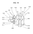
- FIG.14 is a view for explaining a basic constitution of other related art.
- a hemming apparatus 9100 is constituted by guide cylinders 9103, 9103 fixedly provided at a support member 9102 attached to a front end of a robot arm 9101, slide shafts 9104, 9104 slidably guided to be supported by the guide cylinders 9103, 9103, sliders 9105, 9105 fixed to the slide shafts 9104, 9104, a cylinder 9106 coupled to the sliders 9105, 9105 and fixedly provided to the support member 9102, a hemming roller 9107 axially supported rotatably by the sliders 9105, 9105, a guide roller 9108 axially supported by the support member 9102, a guide rail 9111 for preparatory bending for guiding the guide roller 9108 and provided to a lower die 9109 to be inclined in a lower direction, and a guide rail 9112 for regular bending for guiding the guide roller 9108 and provided to the lower die 9109 vertically in a lower
- the guide roller 9108 is engaged with the guide rail 9112 for regular bending.
- the hemming roller 9107 is disposed in a horizontal direction.
- regular bending working of constituting a pinched state is carried out by folding to bend an end hem 9114 of a lower side sheet 9113 which has been preparatorily bent by 45° over an end hem 9116 of an upper side sheet 9115. Hems of the lower side sheet 9113 and the upper side sheet 9115 can be connected thereby.
- the guide roller 9108 is constituted by a shape similar to that of a flanged wheel, and therefore, when the guide rail 9112 for regular bending is bent abruptly to some degree or more, the guide roller 9108 is derailed. Therefore, the hemming apparatus 9100 of the related art of Fig.14 is applicable only to an end hem 9114 gradually bent in a head and tail direction of the drawing.
- a radius of curvature is an inverse number of a radius.
- a work of a bonnet or the like of a vehicle includes corner portions having large radii of curvature at four corners thereof. Such a work cannot be worked by the hemming apparatus 9100.
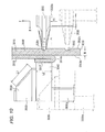
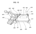
- FIG.15 is a view for explaining a basic constitution of still other related art.
- a hemming forming apparatus 9200 is constituted by a jig 9203 for receiving an outer panel 9202 mounted with an inner panel 9201, an articulated robot 9205 mounted on a conveyor apparatus 9204 arranged in a side direction of the jig 9203, a roller holder 9207 attached to a front end of a robot arm 9206 of the articulated 9205, a forming roller 9208 attached to a front end of the roller holder 9207, die driving apparatus 9209 respectively arranged at vicinities of four corner portions of the jig 9203, and forming dies 9211 respectively attached to the die driving apparatus 9209.
- the forming roller 9208 is run by being pressed from an upper side substantially at a linear portion having a small radius of curvature, by pressing to form the four corner portions having large radii of curvature respectively by the forming dies 9211, hemming working can be finished by folding to bend a fold-to-bend portion provided to the outer panel 9202 to the inner panel 9201.
- the hemming forming apparatus 9200 of the related art of Fig.15 the linear portion of the work is worked by the forming roller 9208, and the four corner portions of the work are worked by the forming dies 9211. 4 pieces of the forming dies 9211 are needed, and therefore, the hemming forming apparatus 9200 becomes expensive.
- hemming working is difficult for the portion having a large radius of curvature, and according to the related art of Fig.15 , although hemming working of the portion having the large curvature can be carried out, the hemming apparatus becomes expensive.
- a hemming working method of pinching a work by a moving die and a roller and subjecting a flange provided at an end portion of the work to hemming working is provided with an approaching step of holding the moving die by carrying means and making the moving die approach the work, a floating step of making the moving die displaceable relative to the work by reducing a force of the carrying means for maintaining an attitude thereof, and a contacting step of bringing a surface of the moving die into contact with the work by mounting means provided at the moving die in a state of holding the moving die by the carrying means.
- the approaching step can be constituted by a high speed by setting the carrying means to a large output, and the work can be prevented from being deformed at a contacting step by setting the mounting means to a low output.
- a hemming working apparatus is provided with a moving die and a roller for pinching a work and subjecting a flange provided at an end portion of the work to hemming working, carrying means for making the moving die approach the work, adjusting means for reducing a force of maintaining an attitude when the carrying means makes the moving die approach the work, and mounting means provided at the moving die for bringing a surface of the moving die into contact with the work in a state of holding the moving die by the carrying means.
- the maintaining force adjusting means the force of the carrying means for maintaining the attitude is reduced when the moving die approaches the work, and therefore, the rigidity of the movable portion of the carrying means is lowered. Therefore, when the moving die is mounted to the work by the mounting means, the moving die is brought into contact with the work while being displaced to constitute the pertinent attitude in conformity with the shape of the surface.
- the carrying means is brought into the floating state and the moving die is made to be displaceable, and the moving die is brought into contact with the work by the mounting means.
- the rigidity of the movable portion of the carrying means is lowered, and therefore, the movable portion is pertinently deformed, and the moving die is brought into contact with the work while being displaced to constitute the pertinent attitude in conformity with the surface shape. Therefore, the moving die is not excessively pressed to the work in an unaligned state, and the work can be prevented from being deformed.
- the approaching step can be constituted by a high speed by setting the carrying means to a large output and the work can be prevented from being deformed in the contacting step by setting the mounting means to a low output.
- the moving die is applicable generally regardless of a size of a total of the work. Further, the moving die is applicable also on a production line, and therefore, it is not necessary to provide a space exclusive for hemming working separately from the production line.
- the die in a hemming working method of pinching a work by a die and a roller and subjecting a flange provided at an end portion of the work to hemming working, the die is elastically urged to the work such that the die can be brought into contact with the work at a portion of pressing the work by the roller and the die can be separated from the work at other than the portion of working the work.
- a hemming apparatus is provided with a die and a roller for pinching a work and subjecting a flange provided at an end portion of the work to hemming working, and an elastic member provided between the die and the work and elongatable and contractable in a pressing direction of the roller.
- the die by elastically urging the die to the work such that only the portion pressed by the roller can be brought into contact with the die and the die can be separated from the work at other than the pressed portion, the work can firmly be brought into contact with the die at the pressed portion, the hemming portion can be worked to be folded to bend in a pertinent shape, and warping or deformation of the work can be prevented.
- the work is brought into contact with the die and the hemming portion can be worked to be folded to bend in a pertinent shape. Further, by elastically urging the die to the work such that the die can be separated from the work at other than the pressed portion, a clearance is not forcibly crushed and warping or deformation of the work can be prevented.
- a hemming working method of carrying out hemming working for a flange of a work by using a hemming roller displaceably supported by a moving mechanism when the hemming roller is made to approach the work by the moving mechanism, a displacement of the hemming roller relative to the moving mechanism is restricted, and in the hemming working, the hemming roller is made to be displaceable relative to the moving mechanism.
- a receiving roller for pinching the work along with the hemming roller and displaceably supported by the moving mechanism, when the hemming roller is made to approach the work, the hemming roller and the receiving roller are brought into a state of restricting displacements thereof relative to the moving mechanism, and in the hemming working, the hemming roller and the receiving roller are brought into a state of being displaceable relative to the moving mechanism in a state of maintaining a press force or a distance between the hemming roller and the receiving roller to a predetermined value.
- the hemming roller can be made to follow the flange of the work at a higher speed and accurately and further uniform hemming working can be carried out.
- a hemming working apparatus is provided with a hemming roller for carrying out hemming working for a flange of a work, a receiving roller for pinching the work along with the hemming roller, a hemming unit including a movable mechanism for making the hemming roller and the receiving roller proximate to each other and remote from each other, a moving mechanism for supporting the hemming unit and moving the hemming unit to a predetermined position, and a floating mechanism for displaceably connecting the hemming unit to the moving mechanism.
- the hemming roller can be made to follow the flange at a higher speed and accurately.
- the restricting means capable of restricting a displacement of the hemming unit relative to the moving mechanism by the floating mechanism, the operation at the floating mechanism can be restricted in accordance with an operating step.
- the moving mechanism comprises a base portion connected to the moving mechanism by way of the floating mechanism, and a movable portion constituted to be able to displace the hemming roller and the receiving roller in directions of making the hemming roller and the receiving roller proximate to each other and remote from each other relative to the base portion
- the restricting means comprises a first locking portion provided at the movable portion, and a second locking portion provided at the moving mechanism and engaged with the first locking portion.
- the roller can be made to follow the work at a high speed and accurately along the flange and a hemming working time period can be shortened and a working failure can be avoided. Further, according to the invention, before hemming working, the roller for hemming working can swiftly be positioned to the work, the cycle time can be shortened.
- a hemming working apparatus having a hemming roller for carrying out hemming working for a flange of a work is provided with a moving mechanism for supporting the hemming roller and moving the hemming roller to a predetermined position, and a guide member for guiding the hemming roller along the flange while restricting a displacement of the hemming roller relative to the flange in a direction of a rotating shaft of the hemming roller.
- the hemming roller is provided displaceably in the direction of the rotating shaft of the hemming roller relative to the moving mechanism.
- the hemming roller can be made to follow the flange at a high speed and accurately.
- the roller can be made to follow the flange at a high speed and accurately, the hemming working time period can be shortened and the working failure can be avoided.
- the roller in a hemming working method of folding to bend a flange of a work in a direction of an inner side of the work by a roller, the roller is rolled in an extending direction of the flange while being displaced in a direction orthogonal to the extending direction.
- an angle of folding to bend the flange can be adjusted in accordance with the portion to be worked, a change in the shape becomes gradual, wrinkle or crack or the like can be prevented from being brought about.
- a hemming working apparatus for folding to bend a flange of a work in a direction of an inner side of the work by a roller is provided with a distance restricting portion projected in a direction of erecting the flange and brought into contact with the roller on an outer side of an end portion of the work.
- the distance restricting portion includes an inclined face a height of which is changed in the extending direction.
- a hemming working apparatus for folding to bend a flange of a work in a direction of an inner side of the work by a roller
- the guide portion comprises a parallel portion extended in parallel with the flange, and a separating portion for separating the work in a direction of an outer side thereof by being compared with the parallel portion at a portion of starting and (or) a portion of finishing hemming working for the flange such that the roller is made to be gradually proximate to or remote from the flange.
- the roll hemming method comprising a step of rolling the hemming roller in a first direction of extending the flange such that the ring-like recessed portion passes above the projection by bringing the first circular pillar into contact with an end portion of an outer face of the flange to press and bringing the second circular pillar into contact with a base portion of the outer face of the flange to press, and a step of rolling the hemming roller in a second direction intersected with the first direction such that the ring-like recessed portion passes above the projection by bringing the first circular arc pillar and the second circular pillar into
- the projection in rolling the hemming roller in the first direction of extending the flange, when the ring-like recessed portion is made to pass above the projection above the flange to be folded to bend, the projection is not crushed. Further, when the hemming roller is rolled again the second direction intersected with the first direction and the ring-like recessed portion is made to pass above the projection also at this occasion, a portion remaining as a hollow bulge in the first direction is pressed centering on the projection above the flange. Thereby, the flange becomes a stratified projection centering on the projection of the inner panel.
- the stratified projection is a small projection which is not almost provided with the hollow portion, and a current can be concentrated thereon in spot welding thereafter.
- a hemming roller is provided with a first circular pillar for pressing an end portion of an outer face of a flange, a second circular pillar coaxial with the first circular pillar and having a diameter the same as a diameter of the first circular pillar for pressing a base portion of an outer face of the flange, and a ring-like recessed portion provided between the first circular pillar and the second circular pillar.
- a hemming roller is preferably used for the above-descried roll hemming method and does not press to crush the projection of the inner panel. Further, by rolling the hemming roller in two different directions constituting an intersection thereof by the projection, a hollow bulge is hardly present by the flange centering on the projection, and a current can be concentrated thereon in spot welding thereafter.
- the ring-like recessed portion is constituted by a shape of a circular arc in a section thereof.
- a press mark is difficult to be attached to the flange by a boundary portion between the ring-like recessed portion and the first circular pillar and a boundary portion between the ring-like recessed portion and the second circular pillar.
- a welded structure according to the invention is formed by using a hemming roller having a first circular pillar and a second circular pillar coaxial with each other and having the same diameter and a ring-like recessed portion provided between the circular pillar and the second circular pillar, pinching an inner panel having a projection by folding to bend a flange of an outer panel, providing a stratified projection centering on the projection by rolling the hemming roller such that the ring-like recessed portion passes above the projection in two different directions constituting an intersection thereof by the projection, and carrying out a spot welding by bringing an welding electrode into contact with the stratified projection.
- spot welding a current is made to flow concentratedly to between two layers of the stratified projection, melting is achieved firmly by sufficiently generating heat and a high welding strength is achieved.
- the ring-like recessed portion is made to pass above the projection on the flange to be folded to bend, and therefore, the projection is not crushed. Further, the hemming roller is rolled again in the second direction intersected with the first direction and also at this occasion, the ring-like recessed portion is made to pass above the projection, and therefore, the portion remaining as the bulge along the first direction centering on the projection is pressed on the flange. Thereby, the flange becomes the small stratified projection in which the hollow portion is hardly present centering on the projection of the inner panel and the current can be concentrated thereon in the spot welding thereafter.
- the hemming roller is preferably used for the roll hemming method and does not press to crush the projection of the inner panel. Further, by rolling the hemming roller in two different directions constituting an intersection by the projection, the stratified projection is provided by removing almost the hollow bulge at the bulged portion centering on the projection, and the current can be concentrated thereon in spot welding thereafter.
- the current is mad to flow concentratedly to between two layers of the stratified projection in carrying out spot welding, firm melting is achieved by sufficiently generating heat and the high welding strength is achieved.
- a hemming working method for carrying out hemming working for a hem portion of a work by using a work roller movably supported by moving means including a step of displacing the work roller in a direction of a rotating axis thereof in hemming working.
- the invention is effective for hemming working of a portion having a radius of curvature at the hem portion of the work where the error tends to be increased, for example, a corner portion of the work or a hem portion having a meandering shape.
- the hemming working method for carrying out hemming working for the hem portion of the work by using the work roller movably supported by the moving means, and a guide roller arranged to pinch the work to be opposed to the work roller including a step of relatively changing directions of rolling the work roller and the guide roller in the hemming working.
- the guide roller can be made to follow the hem portion of the work accurately in a state in which the work roller is made to be independent from the guide roller.
- a hemming apparatus comprising a work roller for carrying out hemming working for a hem portion of a work, a guide roller arranged to pinch the work to be opposed to the work roller, a die arranged between the work roller and the guide roller, mounted with the work at a surface thereof, and provided with a guide portion for guiding the guide roller at a back face thereof, moving means for movably supporting the work roller and the guide roller, and position displacing means for displacing positions of the work roller and the guide roller relative to each other by constituting a reference thereof by the guide portion.
- the apparatus even when it is difficult to provide a guide portion of the guide roller along the hem portion of the work as in, for example, a portion of the work having a radius of curvature of the corner portion or the like, working can be carried out by displacing the relative positions of the work roller and the guide roller constituting the reference by the guide portion by the position displacing means. Therefore, the work roller can be made to follow the hem portion of the work accurately.
- a hemming working apparatus comprising a work roller for carrying out hemming working for a hem portion of a work, a guide roller arranged to pinch the work to be opposed to the work roller, a die arranged between the work roller and the guide roller, mounted with the work at a surface thereof, and provided with a guide portion for guiding the guide roller at a back face thereof, moving means for movably supporting the work roller and the guide roller, and direction changing means for changing directions of rolling the work roller and the guide roller relative to each other.
- the apparatus even when it is difficult to provide the guide portion of the guide roller along the hem portion of the work as in the corner portion or the like, working can be carried out by relatively changing the directions of rolling the work roller and the guide roller by the direction changing means. Therefore, the work roller can be made to follow the hem portion of the work accurately in a state of making the work roller independent from the guide roller.
- the work roller can be made to follow accurately to the hem portion of the work.
- the work roller can be made to follow the hem portion of the work by making the work roller independent from the guide roller.
- a hemming working roller used for hemming working of folding to bend a flange erected at a work
- the hemming working roller comprising a primary bending face comprising a taper face inclined to a roller rotating shaft by a first angle, and a secondary bending face comprising a taper face inclined to the roller rotating shaft by a second angle
- the hemming working roller is used for two stages of hemming working of bending the flange by about a half of a total bending angle by the primary bending face and bending the flange completely by the secondary bending face.
- the hemming working roller is a roller preferable for a work a hem portion of which is bent, includes the primary bending face comprising the taper face and the secondary bending face comprising the taper face.
- the primary bending face comprising the taper face
- the secondary bending face can be made to be in line with the guide portion.
- a peripheral speed difference is not brought about between the secondary bending face and the guide portion, and therefore, there is not a concern of bringing about defect or wear at the secondary bending face or the guide portion.
- a roller hemming apparatus used for hemming working for folding to bend a flange erected at a work
- the roller hemming apparatus including a work mounting member for mounting the work, a hemming working roller having a primary bending face comprising a taper face inclined to a roller rotating shaft by a first angle and a secondary bending face comprising a taper face inclined to the roller rotating shaft by a second angle, a roller moving mechanism for moving the hemming working roller relative to the work along the flange, and a guide portion for guiding the secondary bending face when the flange is bent by the primary bending face.
- the roller hemming apparatus is a roller hemming apparatus preferable for a work a hem portion of which is bent and includes the hemming working roller having the primary bending face comprising the taper face and the secondary bending face comprising the taper face.
- the primary bending is carried out by the primary bending face
- the secondary bending face can be made to be in line with the guide portion.
- a peripheral speed difference is not brought about between the secondary bending face and the guide portion, and therefore, there is not a concern of bringing about defect or wear at the secondary bending face or the guide portion.
- a roller hemming working method of folding to bend a flange erected at a work by a roller comprising a preparing step of preparing a hemming working roller having a primary bending face comprising a taper face inclined to a roller rotating shaft by a first angle and a secondary bending face comprising a taper face inclined to the roller rotating shaft by a second angle, and a guide portion for guiding the secondary bending face when the flange is bent by the primary bending face, a primary bending step of bending the flange by the primary bending face by about a half of a total flange bending angle while making the secondary bending face in line with the guide portion, and a secondary bending step of completely bending the flange by the secondary bending face.
- the roller hemming method is a roller hemming method preferable for a work a hem portion of which is bent and carries out hemming by the hemming working roller having the primary bending face comprising the taper face and the secondary bending face comprising the taper face.
- the primary bending face When primary bending is carried out by the primary bending face, the secondary bending face can be made to be in line with the guide portion.
- a peripheral speed difference is not brought about between the secondary bending face and the guide portion, and therefore, there is not a concern of bringing about defect or wear at the secondary bending face or the guide portion.
- a roller hemming apparatus of folding to bend an erected flange by preparing a die including a guide groove at a lower face thereof and a press roller moved independently from the die and a guide member progressing and regressing to and from the press roller, mounting a plate member including the erected flange at a hem thereof on an upper face of the die, fitting the guide member to the guide groove, and operating the press roller to the erected flange under a state thereof, wherein the guide member includes a spherical member rolled along the guide groove.
- the guide member includes the spherical member rolled along the guide groove.
- the spherical body is not detached from the guide groove having a large radius of curvature. Therefore, there can be provided a roll hemming apparatus which is able to carry out hemming working of a portion having a large radius of curvature and inexpensive.
- the roller hemming apparatus is a simple apparatus constituted by the die having the guide groove, the press roller and the guide member, and therefore, low cost formation of the roller hemming apparatus can easily be achieved.
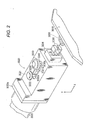
- FIG.1 is an outline perspective view for explaining a behavior of carrying out hemming working for a flange of a wheel arch portion of a vehicle by a hemming working apparatus according to a first exemplary embodiment of the invention.
- a hemming working apparatus 3010 according to the first exemplary embodiment is an apparatus set to a middle step of a production line 3014 for assembling and working a vehicle 3012 as a work in a so-to-speak white body for carrying out hemming working for a flange 3017 of a wheel arch portion 3016 on a left rear wheel side.
- the wheel arch portion 3016 is constituted by a shape of substantially a circular arc of about 180°.
- the flange 3017 is constituted by a shape of being bent by 90° from an end portion 3016a (refer to two-dotted chain line of Fig. 5 ) of the wheel arch portion 3016 to an inner side by 90°.
- the hemming working apparatus 3010 includes a moving die 3018 to be brought into contact with the wheel arch portion 3016 of the vehicle 3012, a robot 3022 as a moving mechanism for moving the moving die 3018 and supporting a hemming unit 3020 at a front end thereof, a photoelectric sensor 3023 for detecting that the vehicle 3012 is carried to a predetermined position of the production line 3014, and a controller 3024 for carrying out a comprehensive control.
- the robot 3022 is of an industrial articulated type, and can move the hemming unit 3020 to an arbitrary position and in an arbitrary attitude by a programmed operation. Further, a vicinity of the robot 3022 is provided with a storing base 3026 arranged with a plurality of kinds of the moving dies 3018 in accordance with kinds of the vehicle 3012, and a position data of the storing base 3026 is stored to the controller 3024.
- the controller 3024 is connected to an external production control computer, not illustrated, for controlling an operation of the production line 3014, and information indicating a kind or the like of the vehicle 3012 carried on the production line 3014 is supplied to the controller 3024.
- the hemming unit 3020 is supported by way of a bracket 3022a fixed to a front end of the robot 3022, and is contained at inside of an outer box 3021 attached to the bracket 3022a, and is provided with a hemming roller 3030 provided to project from a hole portion 3021 a at an upper face of the outer box 3021, and a guide roller 3022 as a receiving roller.
- a chuck 3034 is provided at a front end face of the outer box 3021.
- the chuck 3034 includes a pair of fingers 3036 opened and closed under an operation of the controller 3024 and is used for moving the moving die 3018.
- the hemming roller 3030 and the guide roller 3032 are axially supported rotatably by support shafts 3030a and 3032a. Further, the hemming roller 3030 and the guide roller 3032 are made to be movable in X direction (direction of aligning the support shafts 3030a and 3032a), and can be pressed to a member pinched by the hemming roller 3030 and the guide roller 3032. Further, the hemming roller 3030 and the guide roller 3032 are supported by the robot 3032 by way of a floating mechanism, not illustrated, and can be moved in X direction and Y direction (axial directions of the support shafts 3030a and 3032a) while maintaining positions thereof relative to each other and are moved drivenly and elastically by an external force. That is, the support shaft 3030a and the support shaft 3032a are cooperatively made to be movable in X direction while maintaining an adjusted interval therebetween.
- the hemming roller 3030 is constituted by a taper roller 3038 provided at a front end side, and a circular cylinder roller 3040 provided on a base end side by a structure integral with a taper roller 3038.
- the taper roller 3038 is a frustrum of a circular cone in a converging shape inclined by 45° in a side view thereof, and an edge line length L1 (refer to Fig.7 ) is set to be slightly longer than a height H of the flange 3017.
- the circular cylinder roller 3040 is constituted by a shape of a circular cylinder having a diameter slightly larger than a maximum diameter portion on the base end side of the taper roller 3038.
- the guide roller 3032 is constituted by a shape of a circular disk a surrounding of which is set to a narrow width and made to be engageable with a first groove 3052 or a second groove 3054 (refer to Fig.7 ) provided at the moving die 3018. That is, by the first groove 3052 and the second groove 3054 and the guide roller 3032 operated as a guide member, the hemming roller 3030 is guided along the flange 3017 while restraining a displacement relative to the flange 3017 in Y direction constituting an axial direction of the support shaft 3030a of the hemming roller 3030 and X direction constituting a direction of aligning the support axis 3030a and 3032a. Further, a position in Y direction of the guide roller 3032 coincides with a position of a center of a height L2 (L2/2) of the circular cylinder roller 3040 of the hemming roller 3030 (refer to Fig.7 ).
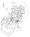
- Fig.3 is a perspective view of the hemming unit 3020
- Fig.4 is a partially sectional side view showing the hemming unit 3020 before hemming working
- Fig.5 is a partially sectional side view showing the hemming unit 3020 in hemming working.
- the outer box 3021 is illustrated perspectively by a two-dotted chain line to be able to optically recognize a structure of the hemming unit 3020.
- the hemming unit 3020 includes the hemming roller 3030 and the guide roller 3032, the support shafts 3030a and 3032a for axially supporting these, a first movable portion 3100 as a movable portion having the support shaft 3032a at an upper end face thereof, a second movable portion 3102 as a movable portion having the support shaft 3032a at an upper end face thereof, a cylinder 3106 for connecting and displacing in X direction the first movable portion 3100 and the second movable portion 3102, and a base portion 3110 for supporting the first movable portion 3100, the second movable portion 3012 and the cylinder 3106 relative to the robot 3022.
- the base portion 3110 is constituted by a shape of a substantially channel-like shape in which a lower side thereof is longer than an upper side thereof in a side view thereof (refer to Fig.4 ), and the base portion 3110 is provided with a third movable portion 3114 displaceably supported in Y direction by a second rail 3025 extended in Y direction to be supported by a support member 3022b fixed to a bracket 3022a and substantially in a channel-like shape in a side view thereof (refer to Fig.4 ) by way of a linear guide 3112, a base 3116 in a rectangular shape projected from a slightly lower portion of a center in Y direction of the third movable portion 3114, a front end support member 3118 in a rectangular shape provided at a front end face of the base 3116, a flat plate 3120a in a rectangular shape projected from an upper portion of the third movable portion 3114 in a direction in parallel with the base 3116, and a partitioning portion 3120b in a rectangular
- first supporting means 3126 and second supporting means 3127 are arranged in series between a side face 3102b of an upper portion of the second movable portion 3120 on a side of the third movable portion 3114, and a side face 3124a projected from a front end portion of an extending portion 3122 extended from the second movable portion 3120 to a side of the third movable portion 3114 in Y direction so as not to be brought into contact with the flat plate 3120a, and the partitioning portion 3120b is provided to partition therebetween.
- a first rail 3128 is extended in parallel with the base 3116 at an upper space of the base 3116 at which the third movable portion 3114 and the front end support member 3118 are opposed to each other. Further, the first movable portion 3100 and the second movable portion 3102 are supported by the first support rail 3128 displaceably in X direction respectively by way of linear guides 3100 and 3132. That is, the first movable portion 3100 and the second movable portion 3102 are supported by the base portion 3110 by way of the linear guides 3130 and 3132 or the like, and these function as a movable mechanism.
- the second movable portion 3102 is supported by the first supporting means 3126 and the second supporting means 3127 drivenly and elastically in X direction by interposing the above-described partitioning portion 3120b. That is, when the second movable portion 3102 is displaced in a direction of being separated from the first movable portion 3100, the second supporting means 3127 is contracted by the partitioning portion 3120b, and when the second movable portion 3102 is displaced in a direction of being proximate to the first movable portion 3100, the first supporting means 3126 is contracted by the partitioning portion 3120b.
- a horizontally projected portion 3022c projected in X direction from a lower end face of the support member 3022b and the base 3116 are drivenly and elastically supported by third supporting means 3138.
- third supporting means 3138 Although a pair of two pieces of the third supporting means are provided to connect end portions on both sides of the horizontally projected portion 3022c and the base 3116, one piece thereof may naturally be constituted to connect center portions in width directions of the horizontally projected portion 3022c and the base 3116.
- the third supporting means 3126, the second supporting means 3127 and the third supporting means 3138 are constructed by similar constitutions
- the first supporting means 3126 is constituted by a shaft portion 3126a and a spring 3126b installed at a surrounding of the shaft portion 3126a
- the second supporting means 3127 is constituted by a shaft portion 3127a and a spring 3127b arranged at a surrounding of the shaft portion 3127a
- the third supporting means 3138 is constituted by a shaft portion 3138a and a spring 3138b installed at a surrounding of the shaft portion 3138a.
- the respective shaft portions 3126a, 3127a, and 3128a may be constituted by hydraulic dampers or pneumatic dampers or the like.
- the first supporting means 3126 and the second supporting means 3127 are constructed by the above-described constitutions, and therefore, as described above, the second movable portion 3102 is supported at the base portion 3110 displaceably in X direction by the linear guide 3132, and drivenly and elastically supported in X direction relative to the base portion 3110 by the first supporting means 3126 and the second supporting means 3127 by way of the partitioning portion 3120b.
- the third supporting means is constructed by the above-described constitution, and therefore, the base 3116 is drivenly and elastically supported in Y direction relative to the horizontally projected portion 3022c fixed to the robot 3022 by the third supporting means.
- the second movable portion 3102 includes one side face 3102a and other side face 3102c extended in a lower direction, the other side face 3102c is provided with a first stopper 3134 as a first locking portion, and the first stopper 3134 is engageable with a second stopper 3136 provided at a front end portion of the horizontally projected portion 3122c. That is, a front end of the first stopper 3134 is constituted by a projected portion substantially in a shape of a frustrum of a circular cone, and the second stopper 3136 is constituted by a recessed portion substantially in a shape of a cone capable of inserting the front end of the first stopper 3134.
- the first stopper 3134 and the second stopper 3136 are engaged in a state in which an interval between the hemming roller 3030 and the guide roller 3032 is maximally opened by extending a rod 3104 of the cylinder 3106, that is, in a state in which the hemming roller 3030 is separated from the vehicle 3012 before hemming working or after hemming working, mentioned later.
- the first stopper 3134 and the second stopper 3136 are not engaged with each other in a state in which the interval between the hemming roller 3030 and the guide roller 3032 is narrowed by retracting the rod 3104 and the cylinder 3106 as shown by Fig.5 , that is, in a state in which the hemming roller 3030 is brought into contact with the vehicle 3012 in hemming working, mentioned later.
- the first movable portion 3100 is brought into contact with and supported by the front end support member 3138 by a press force in a direction opposed to the side of the second movable portion 3102 by the rod 3104 connected to the cylinder 3106.
- the first movable portion 3100 is held in a state of being proximate to the second movable portion 3102 by a force attracted to a side of the second movable portion 3102 by the rod 3104.
- the hemming unit 3020 according to the first exemplary embodiment is constituted as described above. Therefore, in a state in which the first stopper 3134 and the second stopper 3136 are not engaged with each other as shown by Fig.5 , the first movable portion 3100 and the second movable portion 3102 are supported by the base portion 3110 integrally and displaceably in X direction by way of the linear guides 3130 and 3132, and the displacement in X direction is drivenly and elastically supported by the first supporting means 3126 and the second supporting means 3127.
- the base portion 3116 supporting the first movable portion 3100 and the second movable portion 3102 in this way is supported by the robot 3022 displaceably in Y direction by way of the linear guide 3112, the displacement in Y direction is drivenly and elastically supported by the third supporting means 3038. Therefore, in this case, the first movable portion 3100 and the second movable portion 3102, in other words, the hemming roller 3030 and the guide roller 3032 are supported by the robot 3022 displaceably in X direction and Y direction and drivenly and elastically.
- the linear guides 3132, 3130 and 3132, the first supporting means 3126, the second supporting means 3127 and the third supporting means 3138 are operated as the floating mechanism interposed between the hemming unit 3020 and the robot 3022, and a performance of the guide roller 3032 following the first groove 3052 or the second groove 3054 in hemming working is considerably promoted, and the hemming roller 3030 can be made to follow the flange 3017 at high speed and accurately, and details thereof will be described later (refer to Fig.9 and Fig.10 ).
- the hemming roller 3030 and the guide roller 3032 are made to be proximate to position the vehicle 3012 and the moving die 3018, for example, before hemming working, by restricting the floating mechanism, the positioning can swiftly be carried out and details thereof will be described later.
- the moving die 3018 is constituted by constituting a base by a die plate 3029.
- the die plate 3049 is constituted by a plate shape, a side thereof brought into contact with the wheel arch portion 3016 is referred to as a surface 3049a (refer to Fig.7 ) and a face on an opposed side thereof is referred to as a back face 3049b to be differentiated from each other.
- a work side in view from an end portion 3016a of a wheel arch portion 3016 is referred to as an inner side, and a side opposed thereto (lower side in Fig.7 ) is referred as an outer side to be differentiated from each other.
- the die plate 3049 is constituted by a shape of a plate in an arch shape the surface 3049a of which is brought into contact with a surrounding of the wheel arch portion 3016, and the surface 3049a is set to a three-dimensional curved face in conformity with a surface of the vehicle 3012. Therefore, when the moving die 3018 is attached to the wheel arch portion 3016, the first groove 3052 and the second groove 3054 are arranged in parallel with the flange 3017, and the surface 3049a is brought into face contact with the vehicle 3012 by a wide area.
- the moving die 3018 includes an outer side circular arc portion 3050 formed along slightly on an outer side of the end portion 3016a of the wheel arch portion 3016, the first groove 3052 and the second groove 3054 provided in parallel with each other along the outer side circular arc portion 3050 at the back face 3049b, a knob 3056 provided at the back face 3049b, three clamp mechanisms 3058 provided at the surrounding, a pipe 3060 for supplying and recovering a compressed fluid to and from the clamp mechanism 3058, and a control valve 3062 for controlling to switch a fluid supply direction of the pipe 3060 or the like.
- the control valve 3062 is controlled by the controller 3024.
- the first groove 3052 is provided on an outer side of being projected from the end portion 3016a of the flange 3017 on the die plate 3049, and the second groove 3054 is provided on an inner side of the end portion 3016a.
- the moving die 3018 is small-sized since the moving die 3018 is brought into contact only with the surrounding of the wheel arch portion 3016. Further, the moving die 3018 is brought into contact with the vehicle 3012 from a side face thereof, and therefore, the moving die 3018 is not applied with a weight of the vehicle 3122, and the moving die 3018 is not constituted by a load resistant structure, and therefore, the moving die 3018 is set to be light-weighted. Therefore, the moving die 3018 is made to be movable simply and conveniently by the robot 3022 by grabbing the knob 3056 by the chuck 3034 (refer to Fig.1 and Fig.2 ).
- the clamp mechanism 3058 includes a stay 3064 extended from an end portion of the die plate 3049, a cylinder 3066 pivotably provided to the stay 3064, and an opening/closing lever 3068 inclined centering on a support shaft provided at the stay 3064.
- One end portion of the opening/closing lever 3068 constitutes a grip portion 3068a engaged with and held by a reference position of the vehicle 3012, and an end portion on an opposed side is rotatably coupled to a rod 3066a of the cylinder 3066 by way of a support shaft.
- the opening/closing lever 3068 is closed to hold the vehicle 3012 by the grip portion 3068a, and by contracting the rod 3066a, the opening/closing lever 3068 is opened (refer to a two-dotted chain line portion of Fig.6 ), and the moving die 3018 is made to be able to be proximate or separated from the vehicle 3012.
- a stop position of the vehicle 3012 on the production line 3014 is more ore less shifted from a rectified value
- the moving die 3018 is accurately positioned to the wheel arch portion 3016 by the clamp mechanism 3058.
- the outer side circular arc portion 3050 is arranged on an outer side (lower side of Fig.7 ) of the end portion 3016a of the wheel arch portion 3016.
- the first groove 3052 is slightly on an outer side of the end portion 3016a
- the second groove 3054 is on an inner side of the end portion 3016a. That is, the first groove 3052 and the second groove 3054 are arranged at positions substantially symmetrical with each other by constituting a reference by the end portion 3016a and in parallel with each other along the end portion 3016a.
- step S301 information of a vehicle kind of the vehicle 3012 carried successively is confirmed from the production control computer, thereafter, the robot 3022 returns the currently grabbed moving die 3018 to a rectified position of the storing base 3026 and grabs other moving die 3018 in correspondence with the vehicle kind by the chuck 3034.
- the hold and switch operation is not needed, further, when a plurality of pieces of the vehicles 3012 of the same vehicle kind is continuously carried, it is not naturally needed to hold and change the moving die 3018.
- step S302 the operation is at standby until the vehicle 3012 is carried by confirming a signal of the photoelectric sensor 3023.
- the vehicle 3012 is carried by the production line 3014 and is stopped at a predetermined position at a vicinity of the robot 3022.
- the operation proceeds to step S303 at a time point of confirming carrying of the vehicle 3012 by the photoelectric sensor 3023.
- the opening/closing lever 3068 of the clamp mechanism 3058 is closed by bringing the surface 3049a of the moving die 3018 into contact with the wheel arch portion 3016 of the vehicle 3012 by operating the robot 3022 and driving to switch the control valve 3062.
- the moving die 3018 is attached to the wheel arch portion 3016 and is accurately positioned to fix. That is, at step S303, the vehicle 3012 constituting a large-sized weighted object is completely stopped, and by making the small-sized and light-weighted moving die 3018 proximate thereto, positioning and fixing are carried out simply and conveniently.
- the moving die 3018 may be made to be proximate thereto while correcting a path of moving the robot 3022 while confirming a position of the moving die 3018 relative to the wheel arch portion 3016 in real time by a predetermined sensor. Further, positioning may be carried out by providing a reference pin at the moving die 3018 and inserting the reference pin into a predetermined reference hole of the vehicle 3012. Both of the positioning means may naturally be used.
- step S304 after opening the finger 3036 of the chuck 3034, the hemming unit 3020 is temporarily separated from the moving die 3018.
- the hemming unit 3020 is made to be proximate to and positioned to the outer side circular arc portion 3050 of the moving die 3018, and the guide roller 3032 is engaged with the first groove 3052.
- the first stopper 3134 and the second stopper 3136 are engaged with each other by bringing about a state of extending the rod 3014 of the cylinder 3106.
- the interval between the hemming roller 3030 and the guide roller 3032 is brought into a maximally separated state, the flange 3017 and the die plate 3049 is made to be able to be easily inserted to the separated portion, further, by maintaining a state of restricting the floating operation at the hemming unit 302, the hemming roller 3030 and the guide roller 3032 are positioned in a state of being integrally fixed to the robot 3022 without bringing about rocking or rattling.
- the hemming working apparatus 3010 of the embodiment achieves a simple and excellent positioning function of sufficiently separating the interval between the hemming roller 3030 and the guide roller 3032 by only extending the rod 3104 of the cylinder 3016 and preventing rocking or rattling of the hemming unit 3020 including the hemming roller 3030 and the guide roller 3032 by restricting the floating mechanism simultaneously.
- step S304 similar to step S305, the floating operation of the hemming unit 3020 may be restricted, in this case, there can be restrained occurrence of noise sound or vibration at the front end portion of the robot 3022 caused by rocking or rattling of the hemming unit 3020 in an operation of moving the robot 3022.
- step S306 the rod 3014 of the cylinder 3106 is contracted, the guide roller 3032 and the hemming roller 3030 are made to be proximate to each other, and as shown by Fig.7 , the moving die 3018 is pinched by the guide roller 3032 and the circular cylinder roller 3040.
- the flange 3017 is pressed by the taper roller 3038 and is inclined to bend by 45° along the conical face.
- a distance between the guide roller 3032 and the circular cylinder roller 3040 is rectified by a width w between a bottom portion of the first groove 3052 and the surface 3049a and the guide roller 3032 and the circular cylinder roller 3040 are not made to be excessively proximate to each other. Therefore, the flange 3017 is not bent by a rectified amount or more or is not constituted by a wavy shape. Further, the moving die 3018 can firmly be pinched by arranging the guide roller 3032 and the circular cylinder roller 3040 such that positions thereof in Y direction coincide with each other. Thereby, the moving die 3018 is not applied with a moment force and an elastic deformation or a shift can be prevented from being brought about.
- the engagement between the first stopper 3134 and the second stopper 3136 is disengaged and the restriction of the floating mechanism is released at the hemming unit 3020. That is, according to the hemming working apparatus 3010 of the first exemplary embodiment, by a simple operation of retracting the rod 3014 of the cylinder 3106, the operation of pressing the flange 3017 is carried out by the taper roller 3038, further, also the restriction of the floating mechanism is released to be able to prepare for hemming working explained in the following steps.
- a first hemming step of inclining to bend the flange 3017 by 45° in an inner side direction is continuously carried out. That is, there is carried out a first hemming step of rolling the hemming roller 3030 and the guide roller 3032 while rotating the hemming roller 3030 and the guide roller 3032 in directions reverse to each other in a state of maintaining a press force and a distance therebetween to predetermined values and continuously bending the flange 3017 by a conical face of the taper roller 3038.
- the hemming roller 3030 and the guide roller 3032 are supported by the floating mechanism as described above, and therefore, the hemming roller 3030 and the guide roller 3032 can be displaced in X direction and Y direction while maintaining positions thereof relative to each other, and even when more or less error is present in a locus of operating the robot 3022, the guide roller 3032 can be moved by accurately following the first groove 3052, and therefore, a speed of rolling the hemming roller 3030 and the guide roller 3032 can be constituted by a high speed.
- the taper roller 3038 can press and deform the flange 3017 in a rectified direction. Further, an accuracy of operating the robot 3022 is not needed to be an extremely high accuracy, and high speed formation of the operating speed and simplification of control procedure are achieved. Hemming working by the first hemming step is carried out over an entire length of the flange 3017.
- step S308 as shown by a two-dotted chain line portion of Fig.10 , the rod 3104 of the cylinder 3106 is more or less extended, and a distance between the hemming roller 3030 and the guide roller 3032 is slightly prolonged to be separated from the vehicle 3012 and the moving die 3018.
- the rod 3104 is extended more or less as described above in consideration that the distance of moving the hemming unit 3020 at the following step S309 is comparatively short or the like.
- the hemming roller 3030 and the guide roller 3032 are moved in an arrow mark Y1 direction by moving the hemming unit 3020.
- the moving distance is equal to a distance between the first groove 3052 and the second groove 3054.
- the guide roller 3032 is engaged with the second groove 3054 by retracting the rod 3104 of the cylinder 3106. Further, the guide roller 3032 and the hemming roller 3030 are made to be proximate to each other, and as shown by Fig.10 , the moving die 3018 is pressed to pinch by the guide roller 3032 and the circular cylinder roller 3040. In this way, the operating procedure in moving the guide roller 3032 from the first groove 3052 to the second groove 3054 is simple and the guide roller 3032 is only moved in the arrow mark Y1 direction while making the direction of the hemming unit 3020 constant. Further, also the moving distance is comparatively short, and therefore, the shifting is finished in a short period of time.
- the flange 3017 is pressed by the circular cylinder roller 3040 and is bent to be brought into contact with the back face of the wheel arch portion 3016. That is, the flange 3017 is further bent by 45° from the first hemming step, that is, by 90° from an initial angle.
- step S311 by rolling the guide roller 3032 while engaging the guide roller 3032 with the second groove 3054, a second hemming step of folding to bend the flange 3017 to be brought into contact with the back face of the wheel arch portion 3016 is continuously carried out. That is, the second hemming step is carried out by continuously bending the flange 3017 by an outer peripheral circular cylinder face of the circular cylinder roller 3040 by rolling the hemming roller 3030 and the guide roller 3032 in directions reverse to each other in a state of maintaining a press force or a distance between the hemming roller 3030 and the guide roller 3032 to predetermined values.
- the second groove 3054 is provided on the side of the back face 3049b of the die plate 3049, and therefore, the flange 3017 and the die plate 3049 are firmly pressed by being pinched by the circular cylinder roller 3040 and the guide roller 3032, further, a press force is not dispersed to other portion and there is not a stopper of restricting the press force and the press force is concentratedly operated to the flange 3017. Thereby, the flange 3017 is firmly bent.
- the hemming roller 3030 and the guide roller 3032 are moved on an accurate path along the second groove 3054 by the operation of the floating mechanism and the working is carried out over the entire length of the flange 3017.
- step S312 similar to step S308, the rod 3104 of the cylinder 3106 is retracted, and the distance between the hemming roller 3030 and the guide roller 3032 is slightly prolonged to be separated from the moving die 3018. Further, the hemming unit 3020 is temporarily separated from the moving die 3018.
- a processing of opening the moving die 3018 is carried out. That is, after changing the direction of the hemming unit 3020, the hemming unit is made to be proximate to the back face 3049b, the knob 3056 is grabbed by the chuck 3034, further, the opening/closing lever 3068 of the clamp mechanism 3058 is opened by driving to switch the control valve 3062.
- a standby processing is carried out at step S314. That is, the moving die 3018 is separated from the vehicle 3012 by moving the robot 3022 to a predetermined standby position.
- the controller 3024 informs that the hemming working has normally been finished to the production control computer.
- the informed production control computer confirms that a condition is established for other requirement and drives the production line 3014 and carry the vehicle 3012 finished with the hemming working to a next step.
- the hemming unit 3020 including the hemming roller 3030 and the guide roller 3032 is supported by the robot 3022 displaceably in X direction constituting the direction of aligning the support shaft 3030a and the support shaft 3032a and in Y direction constituting the axial directions of the support shaft 3030a and the support shaft 3032a by way of the floating mechanism constituted by the linear guides 3112, 3130 and 3132, the first supporting means 3126, the second supporting means 3127 and the third supporting means 3138, and therefore, a performance of the guide rollers 3032 of following the first groove 3052 and the second groove 3054 in hemming working is significantly promoted, the hemming roller 3030 is made to be able to accurately follow the flange 3017, and a drawback that the guide roller 3032 rides over the first groove 3052 or the second groove 3054 can be avoided.
- the guide roller 3032 can be moved by accurately following the first groove 3052. Therefore, the speed of rolling the hemming roller 3030 and the guide roller 3032 can be constituted by a high speed, and a time period of an operation required for hemming working can be shortened.
- the hemming working apparatus 3010 includes the first stopper 3134 and the second stopper 3136 constituting the restricting means for restricting the floating mechanism, and therefore, the operation of the floating mechanism can be restricted in accordance with respective operation steps. Therefore, by restricting the operation of the floating mechanism in positioning the hemming roller 3030 and the guide roller 3032, the hemming roller 3030 and the guide roller 3032 can accurately and swiftly be positioned in a state of being integrally fixed to the robot 3022 without bringing about rocking or rattling.
- use or restriction of the floating mechanism in accordance with the respective operation steps can be selected integrally with an operation of extracting or an operation of retracting the rod 3014 of the cylinder 3106 of making the hemming roller 3030 and the guide roller 3032 proximate to each other and remote from each other. That is, in positioning the hemming roller 3030 and the guide roller 3032, by extending the rod 3104 for separating the hemming roller 3030 and the guide roller 3032, the first stopper 3134 and the second stopper 3136 are engaged and the floating mechanism is restricted.
- hemming working apparatus 3010 by using the small-sized and light weighted moving die 3018, hemming working can be carried out by bringing the moving die 3018 into contact with the vehicle 3012 carried on the production line 3014, and an exclusive space for hemming working is not needed. Further, hemming working is carried out in the production line 3014 similar to other assembling and working step, and therefore, a productivity is promoted by dispensing with time and labor of carrying the vehicle 3012 to other exclusive space only for the hemming working.
- the hemming working apparatus 3010 working is carried out while bringing the moving die 3018 into contact with a working portion of the work, and therefore, the hemming working apparatus 3010 is applied regardless of the size of the work.
- the moving die 3018 is small-sized and light-weighted, and therefore, a plurality of pieces of the moving dies can be stored to the storing base 3026, storing and control thereof is simple and convenient, the robot 3022 can carry out hemming working by selecting the moving die 3018 in accordance with the vehicle kind, and a general purpose performance is promoted.
- the hemming roller 3030 can be used both in the first roll hemming and the second roll hemming, and therefore, interchange of the roller is not needed.
- the first groove 3052 and the second groove 3054 are provided on the side of the back face 3049b, and therefore, in the second hemming step, the flange 3017 and the die plate 3049 can be pinched to press by the circular cylinder roller 3040 and the guide roller 3032.
- one piece of the robot 3022 can be made to serve as the moving means of the moving die 3018 and the working means of the hemming working.
- the invention is not limited to the above-described embodiment but can naturally adopt various constitutions without deviating from the gist of the invention.
- the operation of engaging the first stopper 3134 and the second stopper 3136 as means for restricting the floating mechanism is operated integrally with operations of making the hemming roller 3030 and the guide roller 3032 proximate to each other and remote from each other
- the invention is not limited thereto but the restricting means may be constituted to operate separately from the operations of making the hemming roller 3030 and the guide roller 3032 proximate to each other and remote from each other to be controlled by the controller 3024 or the like.
- first groove 3052 and the second groove 3054 are not necessarily limited to the groove shape so far as the guide roller 3032 is guided thereby, for example, a peripheral face of the guide roller 3032 may be provided with a ring-groove by constituting a projected rail (guide streak).
- the floating mechanism is applicable also to other than the hemming working apparatus using the guide roller 3032 as in the embodiment, for example, an apparatus of omitting the guide roller 3032 may be constructed by a constitution in which an upper end face of the second movable portion 3012 is arranged with the hemming roller 3030, the front end support member 3138 is extended to a lower side, and the rod 3104 of the cylinder 3106 is fixed to the front end support member 3118.
- the floating mechanism can naturally be provided to operate to only either one of the side of the guide roller 3032 or the side of the hemming roller 3030 in accordance with a condition of using the hemming working apparatus or the like.
- the invention is not limited thereto but is naturally applicable to other portion by setting a corresponding moving die thereto.
- a hem portion of a front wheel house, a hem portion of a door, a hem portion of a bonnet and a hem portion of a trunk and the like in the vehicle 3012 can be pointed out.
- roll hemming is not limited to a case of folding to bend one sheet of a thin plate but, for example, an end portion of an inner panel constituting a thin plate provided separately may be pinched by folding to bend the flange 3017.
Abstract
Description
- The present invention relates to a hemming working method and a hemming working apparatus for folding to bend a hem portion of a work by using a work roller.
- There is carried out hemming working for folding to bend a flange constituted by erecting a hem portion of a panel in a direction of an inner side of the panel with regard to hem portions of a bonnet, a trunk, a door and a wheel house of an automobile. As the hemming working, there can be pointed out roll hemming working of positioning to hold a panel above a die and folding to bend a flange at an end portion of the panel while pressing a roller thereto. In roll hemming working, a fold-to-bend angle is large, and therefore, there is a case in which working is carried out by being processed by a plurality of stages of steps of preparatory bending (or prehemming) and finish bending (or regular hemming) in consideration of a fold-to-bend accuracy.
- As an apparatus for rolling hemming working, there is proposed an apparatus of fixing a die to a work by clamps arranged at a plurality of portions thereof (refer to, for example,
JP-A-06-297046 - It is preferable to form a shape of a work without error to be aligned to a shape of a die, and when the work is constituted by one sheet of a panel member as in a door panel or a bonnet, portions to be worked are few and an error is difficult to be brought about. On the other hand, when the work is constituted by a box structure or the like constituted by welding a plurality of plate members as in a white body, there is a tendency of bringing about a distortion by heat of welding and a clearance is liable to be brought about at an interval from a die.
- Even when a clearance is brought about between a work and a die, in a case in which the work is constituted by one sheet of a panel member, the panel member is temporarily bent to follow a shape of the die in rolling a roller relative to the panel member, and therefore, a portion to be hemmed is pertinently bent.
- However, when the work is constituted by a box structure or the like, the work is highly rigid and bending is not produced, and therefore, a die is not effectively operated at a portion having a clearance and there is a concern of bringing about a wrinkle in a wavy shape at a portion to be hemmed. Further, when a press force of a roller is excessively increased to eliminate a clearance, the work is distorted.
- Hence, it is an object of the invention to provide a hemming working method and working apparatus capable of firmly bringing a work into contact with a die, folding to bend a portion to be hemmed by a pertinent shape and preventing a distortion or a deformation of the work even when the work is constituted by a shape having an error relative to the die.
- Further, as hemming working, there is proposed a method of carrying out hemming working by setting a work to a die provided at an exclusive space for carrying out an exclusive step and rolling a unit held at a front end of a robot along a flange (refer to, for example,
JP-A-07-060370 JP-B2-2924569 - Meanwhile, in an automobile industry in recent times, it is desired to develop a product in a short period of time and fabricate a number of vehicle kinds at the same time and it is desired to shorten a hemming working time period by making a rolling speed of a roller for hemming working high from a view point of further promoting a productivity and shortening a cycle time.
- However, according to the method described in
JP-A-07-060370 - Further, according to the method described in
JP-B2-2924569 - Further, according to the method described in
JP-B2-2924569 - Hence, it is an object of the invention to provide a hemming working method and a hemming working apparatus capable of making a roller follow along a flange at a high speed and accurately by flexibly supporting the roller in hemming working. Further, it is an object of the invention to provide a hemming working method and a hemming working apparatus capable of swiftly positioning a roller before hemming working even in a constitution of flexibly supporting the roller in hemming working as descried above.
- Further, it is an object of the invention to provide a hemming working apparatus capable of making a roller follow along a flange at a high speed and accurately.
- When hemming working is carried out, it is convenient to leave a portion of a flange to be erected. However, according to rolling hemming working of the background art, a roller is vertically pressed to a flange to be folded to bend at a work start portion, and therefore, a change in a stress and a shape at a boundary portion of a portion of leaving a portion of the flange to be erected and a fold-to-bend portion and there is a concern of bringing about a wrinkle.
- Hence, it is an object of the invention to provide a hemming working method and working apparatus capable of realizing a gradual change in a shape and preventing a wrinkle, a crack or the like from being brought about by adjusting a fold-to-bend angle of a flange in accordance with a portion to be worked.
- Further, it is an object of the invention to provide a hemming working method and working apparatus capable of bringing a moving die into contact with a work by a pertinent attitude.
- Further, there is a case in which a panel member of a door or the like of a vehicle is constituted by combining an inner panel and an outer panel. When the inner panel and the outer panel are combined, the inner panel is pinched by carrying out hemming working of folding to bend a flange of the outer panel, thereafter, spot welding is carried out further to ensure a bonding strength.
- In order to firmly carry out spot welding, a projection may be provided at the inner panel, the flange may be folded to bend such that the flange is brought into contact with an upper portion of the projection, thereafter, spot welding may be carried out by pressing a welding electrode to press the projection from a surface of the flange. Thereby, a current is concentrated on the projected portion to achieve firmly melting and a welding stress is promoted.
- In this case, when the projection is pressed to crush by a back face of the flange in folding to bend the flange, an effect of concentrating the current in spot welding is reduced, and therefore, there is desired a measure of folding to bend the flange while leaving the projection.
- In order to prevent a projection or the like of the panel member from being pressed to crush, there is proposed a method of rolling a roller while following recesses and projections by using a hemming roller a surface of which is brought into a gel state (refer to, for example,
JP-Y2-2561596 - Further, in hemming working, when a flange is folded to bend in steps by being divided by a plurality of times, a highly accurate fold-to-bend portion is provided, which is preferable. The applicant has proposed a method of carrying out hemming working by being divided at least by two times in
JP-A-2005-349471 - Meanwhile, according to the hemming roller described in
JP-Y2-2561596 - Hence, it is an object of the invention to provide a hemming roller capable of folding to bend a flange without crushing a projection provided at a panel member, a roll hemming method, and a weld structure welding a panel worked by the method with high strength.
- Further,
JP-Y2-2561596 - Further,
JP-B2-2579530 - Meanwhile, a bonnet, a trunk and a door or the like of an automobile as described above normally includes a corner portion having a small radius of curvature.
- When the above-described corner portion is worked by the apparatus described in
JP-Y2-2561596 - Further, according to the method of
JP-B2-2579530 - Hence, it is an object of the invention to provide a hemming working method and a hemming working apparatus capable of making a work roller accurately follow even a portion having a radius of curvature of a corner portion or the like of a work. Further, it is an object of the invention to provide a hemming working method and a hemming working apparatus having a high general purpose performance of an equipment and capable of reducing cost.
-
Fig.12A and Fig.12B are views for explaining a basic principle of a roller hemming method according to a related art. (The related art is disclosed in, for example,JP-B-07-090299 Fig.12A , arolling hemming apparatus 8100 is constituted by alower die 8102 provided with aguide face 8101 and aflat roller 8104 rotatably supported by arobot hand 8103. - An
outer panel 8107 having aflange 8106 is mounted on thelower die 8102, and aninner panel 8108 is mounted on theouter panel 8107. Further, theflat roller 8104 is rotated while being in line with theguide face 8101 to fold to bend theflange 8106 indicated by an imaginary line by about 45° up to a position indicated by a bold line. The step is referred to as a tackedly bending step or a primary bending step. - Next, as shown by
Fig.12B , a direction of theflat roller 8104 is changed by therobot hand 8103. Further, theflange 8106 indicated by an imaginary line is completely folded to bend up to a position indicated by a bold line. The step is referred to as a regular bending step or a secondary bending step. -
Fig.13B is a view for explaining a problem of the rolling method of the related art. As shown byFig.13A , assume that thework 8110 is a bonnet in which afront hem portion 8111 and arear hem portion 8112 are bent. After the primary bending step, afront end portion 8115 of aflange 8113 becomes remoter from abending center 8116 than abase portion 8114 of theflange 8113. That is, when a radius of thebase portion 8114 is designated notation R1 and a radius of thefront end portion 8115 is designated by notation R2, R1 < R2. As a result, a peripheral length of thefront end portion 8115 becomes larger than a peripheral length of thebase portion 8114. - A similar peripheral length difference is present also at a
guide face 8120 shown inFig.13B . When a radius of one hem (which is proximate to the bending center) 8121 of theguide face 8120 is designated by notation R3 and a radius ofother hem 8122 is designated by notation R4, R3 < R4. As a result, a peripheral length of theother hem 8122 becomes larger than a peripheral length of the onehem 8122. - When a
flat roller 8123 is rotated without being slipped relative to the onehem 8121, a slip is necessarily generated between theother hem 8122 and theflat roller 8123. Alower die 8124 including theguide face 8120 is constituted by hard steel and also theflat roller 8123 is constituted by hard steel. Therefore, at least one of theguide face 8120 and theflat roller 8123 is worn, and it is difficult to continue hemming working. - Therefore, the method of
JP-B-07-090299 work 8110 in which thefront hem portion 8111 and therear hem portion 8112 are bent. - Hence, it is a problem of the invention to provide a roll hemming technology preferable for a work a hem portion of which is bent.
-
Fig.14 is a view for explaining a basic constitution of other related art. Ahemming apparatus 9100 is constituted byguide cylinders support member 9102 attached to a front end of arobot arm 9101,slide shafts guide cylinders sliders slide shafts cylinder 9106 coupled to thesliders support member 9102, a hemmingroller 9107 axially supported rotatably by thesliders guide roller 9108 axially supported by thesupport member 9102, aguide rail 9111 for preparatory bending for guiding theguide roller 9108 and provided to alower die 9109 to be inclined in a lower direction, and aguide rail 9112 for regular bending for guiding theguide roller 9108 and provided to thelower die 9109 vertically in a lower direction. - First, the
guide roller 9108 is engaged with theguide rail 9112 for regular bending. Thereby, the hemmingroller 9107 is disposed in a horizontal direction. Next, by operating to move back thecylinder 9106, regular bending working of constituting a pinched state is carried out by folding to bend anend hem 9114 of alower side sheet 9113 which has been preparatorily bent by 45° over anend hem 9116 of anupper side sheet 9115. Hems of thelower side sheet 9113 and theupper side sheet 9115 can be connected thereby. - Meanwhile, the
guide roller 9108 is constituted by a shape similar to that of a flanged wheel, and therefore, when theguide rail 9112 for regular bending is bent abruptly to some degree or more, theguide roller 9108 is derailed. Therefore, thehemming apparatus 9100 of the related art ofFig.14 is applicable only to anend hem 9114 gradually bent in a head and tail direction of the drawing. - Further, abrupt bending can be reread as "large radius of curvature" and gradual bending can be reread as "small radius of curvature". A radius of curvature is an inverse number of a radius. A work of a bonnet or the like of a vehicle includes corner portions having large radii of curvature at four corners thereof. Such a work cannot be worked by the
hemming apparatus 9100. -
Fig.15 is a view for explaining a basic constitution of still other related art. Ahemming forming apparatus 9200 is constituted by ajig 9203 for receiving anouter panel 9202 mounted with aninner panel 9201, an articulatedrobot 9205 mounted on aconveyor apparatus 9204 arranged in a side direction of thejig 9203, aroller holder 9207 attached to a front end of arobot arm 9206 of the articulated 9205, a formingroller 9208 attached to a front end of theroller holder 9207, die drivingapparatus 9209 respectively arranged at vicinities of four corner portions of thejig 9203, and forming dies 9211 respectively attached to thedie driving apparatus 9209. - Whereas the forming
roller 9208 is run by being pressed from an upper side substantially at a linear portion having a small radius of curvature, by pressing to form the four corner portions having large radii of curvature respectively by the forming dies 9211, hemming working can be finished by folding to bend a fold-to-bend portion provided to theouter panel 9202 to theinner panel 9201. - That is, according to the
hemming forming apparatus 9200 of the related art ofFig.15 , the linear portion of the work is worked by the formingroller 9208, and the four corner portions of the work are worked by the forming dies 9211. 4 pieces of the forming dies 9211 are needed, and therefore, thehemming forming apparatus 9200 becomes expensive. As described above, according to the related art ofFig.14 , hemming working is difficult for the portion having a large radius of curvature, and according to the related art ofFig.15 , although hemming working of the portion having the large curvature can be carried out, the hemming apparatus becomes expensive. - Hence, it is a problem of the invention to provide a roller hemming apparatus which can carry out hemming working of a portion having a large radius of curvature and inexpensive.
- According one or more embodiments of the invention, a hemming working method of pinching a work by a moving die and a roller and subjecting a flange provided at an end portion of the work to hemming working is provided with an approaching step of holding the moving die by carrying means and making the moving die approach the work, a floating step of making the moving die displaceable relative to the work by reducing a force of the carrying means for maintaining an attitude thereof, and a contacting step of bringing a surface of the moving die into contact with the work by mounting means provided at the moving die in a state of holding the moving die by the carrying means.
- By making the moving die displaceable by the floating step and bringing the moving die into contact with the work by the mounting means in this way, a rigidity of a movable portion of the carrying means is lowered, and therefore, the movable portion is pertinently deformed and the moving die is brought into contact with the work to constitute a pertinent attitude in conformity with the shape of the surface.
- Further, by dividedly providing the carrying means and the mounting means, the approaching step can be constituted by a high speed by setting the carrying means to a large output, and the work can be prevented from being deformed at a contacting step by setting the mounting means to a low output.
- According one or more embodiments of the invention, a hemming working apparatus is provided with a moving die and a roller for pinching a work and subjecting a flange provided at an end portion of the work to hemming working, carrying means for making the moving die approach the work, adjusting means for reducing a force of maintaining an attitude when the carrying means makes the moving die approach the work, and mounting means provided at the moving die for bringing a surface of the moving die into contact with the work in a state of holding the moving die by the carrying means.
- In this way, according to the maintaining force adjusting means, the force of the carrying means for maintaining the attitude is reduced when the moving die approaches the work, and therefore, the rigidity of the movable portion of the carrying means is lowered. Therefore, when the moving die is mounted to the work by the mounting means, the moving die is brought into contact with the work while being displaced to constitute the pertinent attitude in conformity with the shape of the surface.
- According to a hemming working method and working apparatus of one or one ore more of embodiments of the invention, the carrying means is brought into the floating state and the moving die is made to be displaceable, and the moving die is brought into contact with the work by the mounting means. At this occasion, the rigidity of the movable portion of the carrying means is lowered, and therefore, the movable portion is pertinently deformed, and the moving die is brought into contact with the work while being displaced to constitute the pertinent attitude in conformity with the surface shape. Therefore, the moving die is not excessively pressed to the work in an unaligned state, and the work can be prevented from being deformed.
- Further, by dividedly providing the carrying means and the mounting means, the approaching step can be constituted by a high speed by setting the carrying means to a large output and the work can be prevented from being deformed in the contacting step by setting the mounting means to a low output.
- Further, according to the moving die capable of being carried, the moving die is applicable generally regardless of a size of a total of the work. Further, the moving die is applicable also on a production line, and therefore, it is not necessary to provide a space exclusive for hemming working separately from the production line.
- According to one or more embodiments of the invention, in a hemming working method of pinching a work by a die and a roller and subjecting a flange provided at an end portion of the work to hemming working, the die is elastically urged to the work such that the die can be brought into contact with the work at a portion of pressing the work by the roller and the die can be separated from the work at other than the portion of working the work.
- Further, according to one or more embodiments of the invention, a hemming apparatus is provided with a die and a roller for pinching a work and subjecting a flange provided at an end portion of the work to hemming working, and an elastic member provided between the die and the work and elongatable and contractable in a pressing direction of the roller.
- In this way, by elastically urging the die to the work such that only the portion pressed by the roller can be brought into contact with the die and the die can be separated from the work at other than the pressed portion, the work can firmly be brought into contact with the die at the pressed portion, the hemming portion can be worked to be folded to bend in a pertinent shape, and warping or deformation of the work can be prevented.
- According to the hemming working method and the working apparatus of one or more embodiments of the invention, even when the work is constituted by a shape having an error relative to the die, at the portion of being pressed by the roller, the work is brought into contact with the die and the hemming portion can be worked to be folded to bend in a pertinent shape. Further, by elastically urging the die to the work such that the die can be separated from the work at other than the pressed portion, a clearance is not forcibly crushed and warping or deformation of the work can be prevented.
- According to one or more embodiments of the invention, in a hemming working method of carrying out hemming working for a flange of a work by using a hemming roller displaceably supported by a moving mechanism, when the hemming roller is made to approach the work by the moving mechanism, a displacement of the hemming roller relative to the moving mechanism is restricted, and in the hemming working, the hemming roller is made to be displaceable relative to the moving mechanism.
- In this way, by bringing about the state of restricting the deformation relative to the moving mechanism of the hemming roller when the hemming roller is made to approach the work, positioning can be carried out accurately and swiftly without bringing about rocking or rattling of the hemming roller. Further, by bringing the hemming roller into a state of being displaceable relative to the moving mechanism in hemming working, the hemming roller can be made to follow the flange of the work at a higher speed and accurately.
- Further, it is preferable to use a receiving roller for pinching the work along with the hemming roller and displaceably supported by the moving mechanism, when the hemming roller is made to approach the work, the hemming roller and the receiving roller are brought into a state of restricting displacements thereof relative to the moving mechanism, and in the hemming working, the hemming roller and the receiving roller are brought into a state of being displaceable relative to the moving mechanism in a state of maintaining a press force or a distance between the hemming roller and the receiving roller to a predetermined value.
- Thereby, positioning in making the hemming roller approach the work can be made to be further accurate and swift. Further, in hemming working, the hemming roller can be made to follow the flange of the work at a higher speed and accurately and further uniform hemming working can be carried out.
- According to one or more embodiments of the invention, a hemming working apparatus is provided with a hemming roller for carrying out hemming working for a flange of a work, a receiving roller for pinching the work along with the hemming roller, a hemming unit including a movable mechanism for making the hemming roller and the receiving roller proximate to each other and remote from each other, a moving mechanism for supporting the hemming unit and moving the hemming unit to a predetermined position, and a floating mechanism for displaceably connecting the hemming unit to the moving mechanism.
- In this way, by using the floating mechanism of displacebly connecting the hemming unit to the moving mechanism, the hemming roller can be made to follow the flange at a higher speed and accurately.
- Further, when there is provided the restricting means capable of restricting a displacement of the hemming unit relative to the moving mechanism by the floating mechanism, the operation at the floating mechanism can be restricted in accordance with an operating step.
- Further, there may be constructed a constitution in which the moving mechanism comprises a base portion connected to the moving mechanism by way of the floating mechanism, and a movable portion constituted to be able to displace the hemming roller and the receiving roller in directions of making the hemming roller and the receiving roller proximate to each other and remote from each other relative to the base portion, the restricting means comprises a first locking portion provided at the movable portion, and a second locking portion provided at the moving mechanism and engaged with the first locking portion.
- By constructing such a constitution, use and restriction of the floating mechanism can be controlled by further simple constitution and simplification and low cost formation of the apparatus can be achieved.
- According to one or more embodiments of the invention, the roller can be made to follow the work at a high speed and accurately along the flange and a hemming working time period can be shortened and a working failure can be avoided. Further, according to the invention, before hemming working, the roller for hemming working can swiftly be positioned to the work, the cycle time can be shortened.
- According to one or more embodiments of the invention, a hemming working apparatus having a hemming roller for carrying out hemming working for a flange of a work is provided with a moving mechanism for supporting the hemming roller and moving the hemming roller to a predetermined position, and a guide member for guiding the hemming roller along the flange while restricting a displacement of the hemming roller relative to the flange in a direction of a rotating shaft of the hemming roller. The hemming roller is provided displaceably in the direction of the rotating shaft of the hemming roller relative to the moving mechanism.
- In this way, by providing the hemming roller to the moving mechanism displaceably in the direction of the rotating shaft of the hemming roller, in hemming working, the hemming roller can be made to follow the flange at a high speed and accurately.
- According one or more embodiments of the invention, the roller can be made to follow the flange at a high speed and accurately, the hemming working time period can be shortened and the working failure can be avoided.
- According one or more embodiments of the invention, in a hemming working method of folding to bend a flange of a work in a direction of an inner side of the work by a roller, the roller is rolled in an extending direction of the flange while being displaced in a direction orthogonal to the extending direction. In this way, by rolling the roller while being displaced in the direction orthogonal to the extending direction of the flange, an angle of folding to bend the flange can be adjusted in accordance with the portion to be worked, a change in the shape becomes gradual, wrinkle or crack or the like can be prevented from being brought about.
- Further, according one or more embodiments of the invention, a hemming working apparatus for folding to bend a flange of a work in a direction of an inner side of the work by a roller is provided with a distance restricting portion projected in a direction of erecting the flange and brought into contact with the roller on an outer side of an end portion of the work. The distance restricting portion includes an inclined face a height of which is changed in the extending direction.
- In this way, by providing the distance restricting portion having the inclined face the height of which is changed in the extending direction of the flange, a pressing amount of the roller for pressing the flange is restricted in accordance with the portion to be worked, an angle of folding to bend the flange can be adjusted, a change in the shape becomes gradual and wrinkle or crack or the like can be prevented from being brought about.
- Further, according to one or more embodiments of the invention, a hemming working apparatus for folding to bend a flange of a work in a direction of an inner side of the work by a roller is provided with a guide portion for guiding the roller. The guide portion comprises a parallel portion extended in parallel with the flange, and a separating portion for separating the work in a direction of an outer side thereof by being compared with the parallel portion at a portion of starting and (or) a portion of finishing hemming working for the flange such that the roller is made to be gradually proximate to or remote from the flange.
- In this way, by providing the guide portion to be separated to the direction of the outer side of the work, a pressing amount of the roller for pressing the flange is changed in accordance with the portion to be worked, an angle of folding to bend the flange is adjusted, the change in the shape becomes gradual, and wrinkle or crack or the like can be prevented from being brought about.
- According to the hemming working method and the working apparatus of one or more embodiments of the invention, by adjusting the angle of folding to bend the flange in accordance with the portion to be worked, a further gradual change in the shape is realized, and wrinkle or crack or the like can be prevented from being brought about.
- According one or more embodiments of the invention, there is provided a roll hemming method of pinching an inner panel having a projection by folding to bend a flange of an outer panel by using a hemming roller having a first circular pillar and a second circular pillar coaxial with each other and having the same diameter, and a ring-like recessed portion provided between the first circular pillar and the second circular pillar, the roll hemming method comprising a step of rolling the hemming roller in a first direction of extending the flange such that the ring-like recessed portion passes above the projection by bringing the first circular pillar into contact with an end portion of an outer face of the flange to press and bringing the second circular pillar into contact with a base portion of the outer face of the flange to press, and a step of rolling the hemming roller in a second direction intersected with the first direction such that the ring-like recessed portion passes above the projection by bringing the first circular arc pillar and the second circular pillar into contact with the flange to press.
- In this way, in rolling the hemming roller in the first direction of extending the flange, when the ring-like recessed portion is made to pass above the projection above the flange to be folded to bend, the projection is not crushed. Further, when the hemming roller is rolled again the second direction intersected with the first direction and the ring-like recessed portion is made to pass above the projection also at this occasion, a portion remaining as a hollow bulge in the first direction is pressed centering on the projection above the flange. Thereby, the flange becomes a stratified projection centering on the projection of the inner panel. The stratified projection is a small projection which is not almost provided with the hollow portion, and a current can be concentrated thereon in spot welding thereafter.
- Further, according one or more embodiments of the invention, a hemming roller is provided with a first circular pillar for pressing an end portion of an outer face of a flange, a second circular pillar coaxial with the first circular pillar and having a diameter the same as a diameter of the first circular pillar for pressing a base portion of an outer face of the flange, and a ring-like recessed portion provided between the first circular pillar and the second circular pillar. Such a hemming roller is preferably used for the above-descried roll hemming method and does not press to crush the projection of the inner panel. Further, by rolling the hemming roller in two different directions constituting an intersection thereof by the projection, a hollow bulge is hardly present by the flange centering on the projection, and a current can be concentrated thereon in spot welding thereafter.
- In this case, there may be constructed a constitution in which the ring-like recessed portion is constituted by a shape of a circular arc in a section thereof. According to such a circular arc shape of the section, a press mark is difficult to be attached to the flange by a boundary portion between the ring-like recessed portion and the first circular pillar and a boundary portion between the ring-like recessed portion and the second circular pillar.
- Further, a welded structure according to the invention is formed by using a hemming roller having a first circular pillar and a second circular pillar coaxial with each other and having the same diameter and a ring-like recessed portion provided between the circular pillar and the second circular pillar, pinching an inner panel having a projection by folding to bend a flange of an outer panel, providing a stratified projection centering on the projection by rolling the hemming roller such that the ring-like recessed portion passes above the projection in two different directions constituting an intersection thereof by the projection, and carrying out a spot welding by bringing an welding electrode into contact with the stratified projection. According to the welded structure, in carrying out spot welding, a current is made to flow concentratedly to between two layers of the stratified projection, melting is achieved firmly by sufficiently generating heat and a high welding strength is achieved.
- According to the roll hemming method according to one or more embodiments of the invention, when the hemming roller is rolled in the first direction of extending the flange, the ring-like recessed portion is made to pass above the projection on the flange to be folded to bend, and therefore, the projection is not crushed. Further, the hemming roller is rolled again in the second direction intersected with the first direction and also at this occasion, the ring-like recessed portion is made to pass above the projection, and therefore, the portion remaining as the bulge along the first direction centering on the projection is pressed on the flange. Thereby, the flange becomes the small stratified projection in which the hollow portion is hardly present centering on the projection of the inner panel and the current can be concentrated thereon in the spot welding thereafter.
- Further, according to the hemming roller according to one or more embodiments of the invention, the hemming roller is preferably used for the roll hemming method and does not press to crush the projection of the inner panel. Further, by rolling the hemming roller in two different directions constituting an intersection by the projection, the stratified projection is provided by removing almost the hollow bulge at the bulged portion centering on the projection, and the current can be concentrated thereon in spot welding thereafter.
- Further, according to the hemming roller according to one or more embodiments of the invention, the current is mad to flow concentratedly to between two layers of the stratified projection in carrying out spot welding, firm melting is achieved by sufficiently generating heat and the high welding strength is achieved.
- According to one or more embodiments of the invention, there is provided a hemming working method for carrying out hemming working for a hem portion of a work by using a work roller movably supported by moving means including a step of displacing the work roller in a direction of a rotating axis thereof in hemming working.
- According to the hemming working method, even when an error is brought about between a shape of the hem portion of the work and a locus of moving the work roller, by displacing the work roller in the axial direction, the work roller can be made to follow the hem portion of the work accurately. Particularly, according to the invention, the invention is effective for hemming working of a portion having a radius of curvature at the hem portion of the work where the error tends to be increased, for example, a corner portion of the work or a hem portion having a meandering shape.
- Further, according to one or more embodiments of the invention, there is provided the hemming working method for carrying out hemming working for the hem portion of the work by using the work roller movably supported by the moving means, and a guide roller arranged to pinch the work to be opposed to the work roller including a step of relatively changing directions of rolling the work roller and the guide roller in the hemming working.
- According to the hemming working method, even when it is difficult to provide a locus of moving the guide roller along the hem portion of the work as in, for example, the corner portion of the work, by relatively changing the directions of rolling the work roller and the guide roller, the guide roller can be made to follow the hem portion of the work accurately in a state in which the work roller is made to be independent from the guide roller.
- According to one or more embodiments of the invention, there is provided a hemming apparatus comprising a work roller for carrying out hemming working for a hem portion of a work, a guide roller arranged to pinch the work to be opposed to the work roller, a die arranged between the work roller and the guide roller, mounted with the work at a surface thereof, and provided with a guide portion for guiding the guide roller at a back face thereof, moving means for movably supporting the work roller and the guide roller, and position displacing means for displacing positions of the work roller and the guide roller relative to each other by constituting a reference thereof by the guide portion.
- According to the apparatus, even when it is difficult to provide a guide portion of the guide roller along the hem portion of the work as in, for example, a portion of the work having a radius of curvature of the corner portion or the like, working can be carried out by displacing the relative positions of the work roller and the guide roller constituting the reference by the guide portion by the position displacing means. Therefore, the work roller can be made to follow the hem portion of the work accurately.
- Further, according to one or more embodiments of the invention, there is provided a hemming working apparatus comprising a work roller for carrying out hemming working for a hem portion of a work, a guide roller arranged to pinch the work to be opposed to the work roller, a die arranged between the work roller and the guide roller, mounted with the work at a surface thereof, and provided with a guide portion for guiding the guide roller at a back face thereof, moving means for movably supporting the work roller and the guide roller, and direction changing means for changing directions of rolling the work roller and the guide roller relative to each other.
- According to the apparatus, even when it is difficult to provide the guide portion of the guide roller along the hem portion of the work as in the corner portion or the like, working can be carried out by relatively changing the directions of rolling the work roller and the guide roller by the direction changing means. Therefore, the work roller can be made to follow the hem portion of the work accurately in a state of making the work roller independent from the guide roller.
- According to the invention, even when an error is brought about between, for example, the shape of the hem portion of the work and the locus of moving the work roller for working the hem portion, by displacing the work roller and the guide roller in the axial direction, the work roller can be made to follow accurately to the hem portion of the work. Further, according to the invention, even when it is difficult to provide, for example, the guide portion of the guide roller along the hem portion of the work, by relatively changing the directions of rolling the work roller and the guide roller, the work roller can be made to follow the hem portion of the work by making the work roller independent from the guide roller.
- Therefore, derailing of the guide roller from the guide portion, or biting to the guide portion or the like can firmly be prevented, and the work roller can be made to follow accurately along the shape of the hem portion of the work. Further, hemming working of the linear portion of the work and the portion having the radius of curvature of the corner portion or the like can be carried out by one piece of the hemming working apparatus, a general purpose performance of equipment can be promoted and cost can be reduced.
- According to one or more embodiments of the invention, there is provided a hemming working roller used for hemming working of folding to bend a flange erected at a work, the hemming working roller comprising a primary bending face comprising a taper face inclined to a roller rotating shaft by a first angle, and a secondary bending face comprising a taper face inclined to the roller rotating shaft by a second angle, wherein the hemming working roller is used for two stages of hemming working of bending the flange by about a half of a total bending angle by the primary bending face and bending the flange completely by the secondary bending face.
- The hemming working roller is a roller preferable for a work a hem portion of which is bent, includes the primary bending face comprising the taper face and the secondary bending face comprising the taper face. When primary bending is carried out by the primary bending face, the secondary bending face can be made to be in line with the guide portion. At this occasion, a peripheral speed difference is not brought about between the secondary bending face and the guide portion, and therefore, there is not a concern of bringing about defect or wear at the secondary bending face or the guide portion.
- According to one or more embodiments of the invention, there is provided a roller hemming apparatus used for hemming working for folding to bend a flange erected at a work, the roller hemming apparatus including a work mounting member for mounting the work, a hemming working roller having a primary bending face comprising a taper face inclined to a roller rotating shaft by a first angle and a secondary bending face comprising a taper face inclined to the roller rotating shaft by a second angle, a roller moving mechanism for moving the hemming working roller relative to the work along the flange, and a guide portion for guiding the secondary bending face when the flange is bent by the primary bending face.
- The roller hemming apparatus is a roller hemming apparatus preferable for a work a hem portion of which is bent and includes the hemming working roller having the primary bending face comprising the taper face and the secondary bending face comprising the taper face. When the primary bending is carried out by the primary bending face, the secondary bending face can be made to be in line with the guide portion. At this occasion, a peripheral speed difference is not brought about between the secondary bending face and the guide portion, and therefore, there is not a concern of bringing about defect or wear at the secondary bending face or the guide portion.
- According to one or more embodiments of the invention, there is provided a roller hemming working method of folding to bend a flange erected at a work by a roller, the roller hemming working method comprising a preparing step of preparing a hemming working roller having a primary bending face comprising a taper face inclined to a roller rotating shaft by a first angle and a secondary bending face comprising a taper face inclined to the roller rotating shaft by a second angle, and a guide portion for guiding the secondary bending face when the flange is bent by the primary bending face, a primary bending step of bending the flange by the primary bending face by about a half of a total flange bending angle while making the secondary bending face in line with the guide portion, and a secondary bending step of completely bending the flange by the secondary bending face.
- The roller hemming method is a roller hemming method preferable for a work a hem portion of which is bent and carries out hemming by the hemming working roller having the primary bending face comprising the taper face and the secondary bending face comprising the taper face. When primary bending is carried out by the primary bending face, the secondary bending face can be made to be in line with the guide portion. At this occasion, a peripheral speed difference is not brought about between the secondary bending face and the guide portion, and therefore, there is not a concern of bringing about defect or wear at the secondary bending face or the guide portion.
- According to one or more embodiments of the invention, there is provided a roller hemming apparatus of folding to bend an erected flange by preparing a die including a guide groove at a lower face thereof and a press roller moved independently from the die and a guide member progressing and regressing to and from the press roller, mounting a plate member including the erected flange at a hem thereof on an upper face of the die, fitting the guide member to the guide groove, and operating the press roller to the erected flange under a state thereof, wherein the guide member includes a spherical member rolled along the guide groove.
- The guide member includes the spherical member rolled along the guide groove. The spherical body is not detached from the guide groove having a large radius of curvature. Therefore, there can be provided a roll hemming apparatus which is able to carry out hemming working of a portion having a large radius of curvature and inexpensive.
- In addition thereto, the roller hemming apparatus is a simple apparatus constituted by the die having the guide groove, the press roller and the guide member, and therefore, low cost formation of the roller hemming apparatus can easily be achieved.
- Other aspects and advantages of the invention will be apparent from the following description, the drawings and the claims.
-
- [
Fig.1] Fig.1 is an outline perspective view for explaining a behavior of carrying out hemming working for a flange of a wheel arch portion of a vehicle by a hemming working apparatus according to a first exemplary embodiment. - [
Fig.2] Fig.2 is a perspective view of a hemming unit provided at a front end of a robot of a hemming working apparatus according to the first exemplary embodiment. - [
Fig.3] Fig.3 is a perspective view of the hemming unit according to the first exemplary embodiment. - [
Fig.4] Fig.4 is a partially sectional side view showing the hemming unit before hemming working. - [
Fig.5] Fig.5 is a partially sectional side view showing the hemming unit in hemming working. - [
Fig.6] Fig.6 is a perspective view of a moving die fixed to a wheel arch portion. - [
Fig.7] Fig.7 is an enlarged sectional view viewed from VII-VII arrow mark shown inFig.6 . - [
Fig.8] Fig.8 is a flowchart showing a procedure of a hemming working method by the hemming working apparatus according to the first exemplary embodiment. - [
Fig.9] Fig.9 is a partially sectional perspective view of a wheel arch portion of a vehicle, a hemming roller and a guide roller in carrying out a first hemming step. - [
Fig.10] Fig. 10 is a sectional view showing positions of the hemming roller, the guide roller, a flange and a moving die at the second hemming step. - [
Fig.11] Fig.11 is a partially sectional perspective view of the wheel arch portion of the vehicle, the hemming roller and the guide roller in carrying out the second hemming step. - [
Fig.12] Fig.12A and Fig.12B are views for explaining a basic principle of a related art. - [
Fig.13] Fig.13A and Fig.13B are views for explaining a problem of a related art. - [
Fig.14] Fig.14 is a view for explaining a basic constitution of other related art. - [
Fig.15] Fig.15 is a view for explaining a basic constitution of still other related art. - An explanation will be given of a hemming working method and a hemming working apparatus according to exemplary embodiments of the invention in reference to the drawings as follows.
-
Fig.1 is an outline perspective view for explaining a behavior of carrying out hemming working for a flange of a wheel arch portion of a vehicle by a hemming working apparatus according to a first exemplary embodiment of the invention. Ahemming working apparatus 3010 according to the first exemplary embodiment is an apparatus set to a middle step of aproduction line 3014 for assembling and working avehicle 3012 as a work in a so-to-speak white body for carrying out hemming working for aflange 3017 of awheel arch portion 3016 on a left rear wheel side. Thewheel arch portion 3016 is constituted by a shape of substantially a circular arc of about 180°. In a state before working by thehemming working apparatus 3010, theflange 3017 is constituted by a shape of being bent by 90° from anend portion 3016a (refer to two-dotted chain line ofFig. 5 ) of thewheel arch portion 3016 to an inner side by 90°. - As shown by
Fig.1 , thehemming working apparatus 3010 includes a movingdie 3018 to be brought into contact with thewheel arch portion 3016 of thevehicle 3012, arobot 3022 as a moving mechanism for moving the movingdie 3018 and supporting ahemming unit 3020 at a front end thereof, aphotoelectric sensor 3023 for detecting that thevehicle 3012 is carried to a predetermined position of theproduction line 3014, and acontroller 3024 for carrying out a comprehensive control. - The
robot 3022 is of an industrial articulated type, and can move thehemming unit 3020 to an arbitrary position and in an arbitrary attitude by a programmed operation. Further, a vicinity of therobot 3022 is provided with astoring base 3026 arranged with a plurality of kinds of the moving dies 3018 in accordance with kinds of thevehicle 3012, and a position data of thestoring base 3026 is stored to thecontroller 3024. Thecontroller 3024 is connected to an external production control computer, not illustrated, for controlling an operation of theproduction line 3014, and information indicating a kind or the like of thevehicle 3012 carried on theproduction line 3014 is supplied to thecontroller 3024. - As shown by
Fig.2 , thehemming unit 3020 is supported by way of abracket 3022a fixed to a front end of therobot 3022, and is contained at inside of anouter box 3021 attached to thebracket 3022a, and is provided with ahemming roller 3030 provided to project from ahole portion 3021 a at an upper face of theouter box 3021, and aguide roller 3022 as a receiving roller. Further, achuck 3034 is provided at a front end face of theouter box 3021. Thechuck 3034 includes a pair offingers 3036 opened and closed under an operation of thecontroller 3024 and is used for moving the movingdie 3018. - The hemming
roller 3030 and theguide roller 3032 are axially supported rotatably bysupport shafts roller 3030 and theguide roller 3032 are made to be movable in X direction (direction of aligning thesupport shafts roller 3030 and theguide roller 3032. Further, the hemmingroller 3030 and theguide roller 3032 are supported by therobot 3032 by way of a floating mechanism, not illustrated, and can be moved in X direction and Y direction (axial directions of thesupport shafts support shaft 3030a and thesupport shaft 3032a are cooperatively made to be movable in X direction while maintaining an adjusted interval therebetween. - The hemming
roller 3030 is constituted by ataper roller 3038 provided at a front end side, and acircular cylinder roller 3040 provided on a base end side by a structure integral with ataper roller 3038. Thetaper roller 3038 is a frustrum of a circular cone in a converging shape inclined by 45° in a side view thereof, and an edge line length L1 (refer toFig.7 ) is set to be slightly longer than a height H of theflange 3017. Thecircular cylinder roller 3040 is constituted by a shape of a circular cylinder having a diameter slightly larger than a maximum diameter portion on the base end side of thetaper roller 3038. - The
guide roller 3032 is constituted by a shape of a circular disk a surrounding of which is set to a narrow width and made to be engageable with afirst groove 3052 or a second groove 3054 (refer toFig.7 ) provided at the movingdie 3018. That is, by thefirst groove 3052 and thesecond groove 3054 and theguide roller 3032 operated as a guide member, the hemmingroller 3030 is guided along theflange 3017 while restraining a displacement relative to theflange 3017 in Y direction constituting an axial direction of thesupport shaft 3030a of the hemmingroller 3030 and X direction constituting a direction of aligning thesupport axis guide roller 3032 coincides with a position of a center of a height L2 (L2/2) of thecircular cylinder roller 3040 of the hemming roller 3030 (refer toFig.7 ). - Here, the
hemming unit 3020 will be explained in details in reference toFig.3 through Fig.5 .Fig.3 is a perspective view of thehemming unit 3020,Fig.4 is a partially sectional side view showing thehemming unit 3020 before hemming working, andFig.5 is a partially sectional side view showing thehemming unit 3020 in hemming working. Further, inFig.3 through Fig.5 , theouter box 3021 is illustrated perspectively by a two-dotted chain line to be able to optically recognize a structure of thehemming unit 3020. - The
hemming unit 3020 includes the hemmingroller 3030 and theguide roller 3032, thesupport shafts movable portion 3100 as a movable portion having thesupport shaft 3032a at an upper end face thereof, a secondmovable portion 3102 as a movable portion having thesupport shaft 3032a at an upper end face thereof, acylinder 3106 for connecting and displacing in X direction the firstmovable portion 3100 and the secondmovable portion 3102, and abase portion 3110 for supporting the firstmovable portion 3100, the secondmovable portion 3012 and thecylinder 3106 relative to therobot 3022. - The
base portion 3110 is constituted by a shape of a substantially channel-like shape in which a lower side thereof is longer than an upper side thereof in a side view thereof (refer toFig.4 ), and thebase portion 3110 is provided with a thirdmovable portion 3114 displaceably supported in Y direction by asecond rail 3025 extended in Y direction to be supported by asupport member 3022b fixed to abracket 3022a and substantially in a channel-like shape in a side view thereof (refer toFig.4 ) by way of alinear guide 3112, abase 3116 in a rectangular shape projected from a slightly lower portion of a center in Y direction of the thirdmovable portion 3114, a frontend support member 3118 in a rectangular shape provided at a front end face of thebase 3116, aflat plate 3120a in a rectangular shape projected from an upper portion of the thirdmovable portion 3114 in a direction in parallel with thebase 3116, and apartitioning portion 3120b in a rectangular shape provided at a front end portion of theflat plat 3120a in parallel with the thirdmovable portion 3114. Further, first supportingmeans 3126 and second supporting means 3127 are arranged in series between aside face 3102b of an upper portion of the second movable portion 3120 on a side of the thirdmovable portion 3114, and aside face 3124a projected from a front end portion of an extendingportion 3122 extended from the second movable portion 3120 to a side of the thirdmovable portion 3114 in Y direction so as not to be brought into contact with theflat plate 3120a, and thepartitioning portion 3120b is provided to partition therebetween. - Further, a
first rail 3128 is extended in parallel with thebase 3116 at an upper space of the base 3116 at which the thirdmovable portion 3114 and the frontend support member 3118 are opposed to each other. Further, the firstmovable portion 3100 and the secondmovable portion 3102 are supported by thefirst support rail 3128 displaceably in X direction respectively by way oflinear guides movable portion 3100 and the secondmovable portion 3102 are supported by thebase portion 3110 by way of thelinear guides movable portion 3102 is supported by the first supporting means 3126 and the second supporting means 3127 drivenly and elastically in X direction by interposing the above-describedpartitioning portion 3120b. That is, when the secondmovable portion 3102 is displaced in a direction of being separated from the firstmovable portion 3100, the second supporting means 3127 is contracted by thepartitioning portion 3120b, and when the secondmovable portion 3102 is displaced in a direction of being proximate to the firstmovable portion 3100, the first supporting means 3126 is contracted by thepartitioning portion 3120b. - Further, a horizontally projected
portion 3022c projected in X direction from a lower end face of thesupport member 3022b and thebase 3116 are drivenly and elastically supported by third supporting means 3138. Although a pair of two pieces of the third supporting means are provided to connect end portions on both sides of the horizontally projectedportion 3022c and thebase 3116, one piece thereof may naturally be constituted to connect center portions in width directions of the horizontally projectedportion 3022c and thebase 3116. - Further, all of the third supporting means 3126, the second supporting means 3127 and the third supporting means 3138 are constructed by similar constitutions, the first supporting means 3126 is constituted by a
shaft portion 3126a and aspring 3126b installed at a surrounding of theshaft portion 3126a, and the second supporting means 3127 is constituted by ashaft portion 3127a and aspring 3127b arranged at a surrounding of theshaft portion 3127a. Similarly, the third supporting means 3138 is constituted by ashaft portion 3138a and aspring 3138b installed at a surrounding of theshaft portion 3138a. Further, therespective shaft portions - The first supporting means 3126 and the second supporting means 3127 are constructed by the above-described constitutions, and therefore, as described above, the second
movable portion 3102 is supported at thebase portion 3110 displaceably in X direction by thelinear guide 3132, and drivenly and elastically supported in X direction relative to thebase portion 3110 by the first supporting means 3126 and the second supporting means 3127 by way of thepartitioning portion 3120b. Similarly, the third supporting means is constructed by the above-described constitution, and therefore, thebase 3116 is drivenly and elastically supported in Y direction relative to the horizontally projectedportion 3022c fixed to therobot 3022 by the third supporting means. - Meanwhile, the second
movable portion 3102 includes oneside face 3102a andother side face 3102c extended in a lower direction, theother side face 3102c is provided with afirst stopper 3134 as a first locking portion, and thefirst stopper 3134 is engageable with asecond stopper 3136 provided at a front end portion of the horizontally projected portion 3122c. That is, a front end of thefirst stopper 3134 is constituted by a projected portion substantially in a shape of a frustrum of a circular cone, and thesecond stopper 3136 is constituted by a recessed portion substantially in a shape of a cone capable of inserting the front end of thefirst stopper 3134. Therefore, as shown byFig.4 , thefirst stopper 3134 and thesecond stopper 3136 are engaged in a state in which an interval between the hemmingroller 3030 and theguide roller 3032 is maximally opened by extending arod 3104 of thecylinder 3106, that is, in a state in which thehemming roller 3030 is separated from thevehicle 3012 before hemming working or after hemming working, mentioned later. On the other hand, thefirst stopper 3134 and thesecond stopper 3136 are not engaged with each other in a state in which the interval between the hemmingroller 3030 and theguide roller 3032 is narrowed by retracting therod 3104 and thecylinder 3106 as shown byFig.5 , that is, in a state in which thehemming roller 3030 is brought into contact with thevehicle 3012 in hemming working, mentioned later. - Further, in the state in which the
rod 3104 of thecylinder 3106 is extended and thefirst stopper 3134 and thesecond stopper 3136 are engaged (refer toFig.4 ), the firstmovable portion 3100 is brought into contact with and supported by the frontend support member 3138 by a press force in a direction opposed to the side of the secondmovable portion 3102 by therod 3104 connected to thecylinder 3106. On the other hand, in the state in which therod 3104 of thecylinder 3106 is contracted and thefirst stopper 3134 and thesecond stopper 3136 are not engaged with each other (refer toFig.5 ), the firstmovable portion 3100 is held in a state of being proximate to the secondmovable portion 3102 by a force attracted to a side of the secondmovable portion 3102 by therod 3104. - The
hemming unit 3020 according to the first exemplary embodiment is constituted as described above. Therefore, in a state in which thefirst stopper 3134 and thesecond stopper 3136 are not engaged with each other as shown byFig.5 , the firstmovable portion 3100 and the secondmovable portion 3102 are supported by thebase portion 3110 integrally and displaceably in X direction by way of thelinear guides base portion 3116 supporting the firstmovable portion 3100 and the secondmovable portion 3102 in this way is supported by therobot 3022 displaceably in Y direction by way of thelinear guide 3112, the displacement in Y direction is drivenly and elastically supported by the third supporting means 3038. Therefore, in this case, the firstmovable portion 3100 and the secondmovable portion 3102, in other words, the hemmingroller 3030 and theguide roller 3032 are supported by therobot 3022 displaceably in X direction and Y direction and drivenly and elastically. That is, thelinear guides hemming unit 3020 and therobot 3022, and a performance of theguide roller 3032 following thefirst groove 3052 or thesecond groove 3054 in hemming working is considerably promoted, and thehemming roller 3030 can be made to follow theflange 3017 at high speed and accurately, and details thereof will be described later (refer toFig.9 andFig.10 ). - On the other hand, in a state in which the
first stopper 3134 and thesecond stopper 3136 are engaged as shown byFig.4 , the displacement of the firstmovable portion 3100 and the secondmovable portion 3102 in X direction is restricted by a force of extending therod 3104 of thecylinder 3106, further, the displacement of thebase portion 3100 in Y direction is restricted by engaging thestopper 3134 and thesecond stopper 3136. In this case, a floating operation by the floating mechanism is restricted, and thehemming roller 3030 and theguide roller 3032 are fixedly supported by therobot 3022. Therefore, when the hemmingroller 3030 and theguide roller 3032 are made to be proximate to position thevehicle 3012 and the movingdie 3018, for example, before hemming working, by restricting the floating mechanism, the positioning can swiftly be carried out and details thereof will be described later. - Next, the moving
die 3018 will be explained. As shown byFig.6 , the movingdie 3018 is constituted by constituting a base by a die plate 3029. Thedie plate 3049 is constituted by a plate shape, a side thereof brought into contact with thewheel arch portion 3016 is referred to as asurface 3049a (refer toFig.7 ) and a face on an opposed side thereof is referred to as aback face 3049b to be differentiated from each other. Further, a work side (upper side inFig.7 ) in view from anend portion 3016a of awheel arch portion 3016 is referred to as an inner side, and a side opposed thereto (lower side inFig.7 ) is referred as an outer side to be differentiated from each other. - The
die plate 3049 is constituted by a shape of a plate in an arch shape thesurface 3049a of which is brought into contact with a surrounding of thewheel arch portion 3016, and thesurface 3049a is set to a three-dimensional curved face in conformity with a surface of thevehicle 3012. Therefore, when the movingdie 3018 is attached to thewheel arch portion 3016, thefirst groove 3052 and thesecond groove 3054 are arranged in parallel with theflange 3017, and thesurface 3049a is brought into face contact with thevehicle 3012 by a wide area. - The moving die 3018 includes an outer side
circular arc portion 3050 formed along slightly on an outer side of theend portion 3016a of thewheel arch portion 3016, thefirst groove 3052 and thesecond groove 3054 provided in parallel with each other along the outer sidecircular arc portion 3050 at theback face 3049b, aknob 3056 provided at theback face 3049b, threeclamp mechanisms 3058 provided at the surrounding, apipe 3060 for supplying and recovering a compressed fluid to and from theclamp mechanism 3058, and acontrol valve 3062 for controlling to switch a fluid supply direction of thepipe 3060 or the like. Thecontrol valve 3062 is controlled by thecontroller 3024. Thefirst groove 3052 is provided on an outer side of being projected from theend portion 3016a of theflange 3017 on thedie plate 3049, and thesecond groove 3054 is provided on an inner side of theend portion 3016a. - The moving die 3018 is small-sized since the moving
die 3018 is brought into contact only with the surrounding of thewheel arch portion 3016. Further, the movingdie 3018 is brought into contact with thevehicle 3012 from a side face thereof, and therefore, the movingdie 3018 is not applied with a weight of thevehicle 3122, and the movingdie 3018 is not constituted by a load resistant structure, and therefore, the movingdie 3018 is set to be light-weighted. Therefore, the movingdie 3018 is made to be movable simply and conveniently by therobot 3022 by grabbing theknob 3056 by the chuck 3034 (refer toFig.1 andFig.2 ). - The
clamp mechanism 3058 includes astay 3064 extended from an end portion of thedie plate 3049, acylinder 3066 pivotably provided to thestay 3064, and an opening/closing lever 3068 inclined centering on a support shaft provided at thestay 3064. One end portion of the opening/closing lever 3068 constitutes a grip portion 3068a engaged with and held by a reference position of thevehicle 3012, and an end portion on an opposed side is rotatably coupled to arod 3066a of thecylinder 3066 by way of a support shaft. That is, by extending therod 3066a of thecylinder 3066, the opening/closing lever 3068 is closed to hold thevehicle 3012 by the grip portion 3068a, and by contracting therod 3066a, the opening/closing lever 3068 is opened (refer to a two-dotted chain line portion ofFig.6 ), and the movingdie 3018 is made to be able to be proximate or separated from thevehicle 3012. Although there is a case in which a stop position of thevehicle 3012 on theproduction line 3014 is more ore less shifted from a rectified value, the movingdie 3018 is accurately positioned to thewheel arch portion 3016 by theclamp mechanism 3058. - When the moving
die 3018 is fixed to thewheel arch portion 3016 by theclamp mechanism 3058, as shown byFig.7 , the outer sidecircular arc portion 3050 is arranged on an outer side (lower side ofFig.7 ) of theend portion 3016a of thewheel arch portion 3016. Thefirst groove 3052 is slightly on an outer side of theend portion 3016a, further, thesecond groove 3054 is on an inner side of theend portion 3016a. That is, thefirst groove 3052 and thesecond groove 3054 are arranged at positions substantially symmetrical with each other by constituting a reference by theend portion 3016a and in parallel with each other along theend portion 3016a. - Next, an explanation will be given of a working method of carrying out hemming working with regard to the
flange 3017 of thewheel arch portion 3016 by using thehemming working apparatus 3016 constituted as described above in reference toFig.8 . Processings shown inFig.8 are carried out by the movingdie 3018, thehemming unit 3020 and therobot 3022 mainly under a control by thecontroller 3024. - First, at step S301, information of a vehicle kind of the
vehicle 3012 carried successively is confirmed from the production control computer, thereafter, therobot 3022 returns the currently grabbed movingdie 3018 to a rectified position of thestoring base 3026 and grabs other moving die 3018 in correspondence with the vehicle kind by thechuck 3034. When the corresponding movingdie 3018 has been held already, the hold and switch operation is not needed, further, when a plurality of pieces of thevehicles 3012 of the same vehicle kind is continuously carried, it is not naturally needed to hold and change the movingdie 3018. - At step S302, the operation is at standby until the
vehicle 3012 is carried by confirming a signal of thephotoelectric sensor 3023. Thevehicle 3012 is carried by theproduction line 3014 and is stopped at a predetermined position at a vicinity of therobot 3022. The operation proceeds to step S303 at a time point of confirming carrying of thevehicle 3012 by thephotoelectric sensor 3023. - At step S303, the opening/
closing lever 3068 of theclamp mechanism 3058 is closed by bringing thesurface 3049a of the movingdie 3018 into contact with thewheel arch portion 3016 of thevehicle 3012 by operating therobot 3022 and driving to switch thecontrol valve 3062. Thereby, the movingdie 3018 is attached to thewheel arch portion 3016 and is accurately positioned to fix. That is, at step S303, thevehicle 3012 constituting a large-sized weighted object is completely stopped, and by making the small-sized and light-weighted moving die 3018 proximate thereto, positioning and fixing are carried out simply and conveniently. - Further, the moving
die 3018 may be made to be proximate thereto while correcting a path of moving therobot 3022 while confirming a position of the movingdie 3018 relative to thewheel arch portion 3016 in real time by a predetermined sensor. Further, positioning may be carried out by providing a reference pin at the movingdie 3018 and inserting the reference pin into a predetermined reference hole of thevehicle 3012. Both of the positioning means may naturally be used. - At step S304, after opening the
finger 3036 of thechuck 3034, thehemming unit 3020 is temporarily separated from the movingdie 3018. - At step S305, after changing a direction of the
hemming unit 3020, thehemming unit 3020 is made to be proximate to and positioned to the outer sidecircular arc portion 3050 of the movingdie 3018, and theguide roller 3032 is engaged with thefirst groove 3052. - At this occasion, in the
hemming unit 3020, thefirst stopper 3134 and thesecond stopper 3136 are engaged with each other by bringing about a state of extending therod 3014 of thecylinder 3106. Thereby, the interval between the hemmingroller 3030 and theguide roller 3032 is brought into a maximally separated state, theflange 3017 and thedie plate 3049 is made to be able to be easily inserted to the separated portion, further, by maintaining a state of restricting the floating operation at thehemming unit 302, the hemmingroller 3030 and theguide roller 3032 are positioned in a state of being integrally fixed to therobot 3022 without bringing about rocking or rattling. That is, thehemming working apparatus 3010 of the embodiment achieves a simple and excellent positioning function of sufficiently separating the interval between the hemmingroller 3030 and theguide roller 3032 by only extending therod 3104 of thecylinder 3016 and preventing rocking or rattling of thehemming unit 3020 including thehemming roller 3030 and theguide roller 3032 by restricting the floating mechanism simultaneously. - Therefore, positioning of the hemming
roller 3030 and theguide roller 3032 can accurately and swiftly be carried out, the cycle time can be shortened. Further, even in step S304, similar to step S305, the floating operation of thehemming unit 3020 may be restricted, in this case, there can be restrained occurrence of noise sound or vibration at the front end portion of therobot 3022 caused by rocking or rattling of thehemming unit 3020 in an operation of moving therobot 3022. - At step S306, the
rod 3014 of thecylinder 3106 is contracted, theguide roller 3032 and thehemming roller 3030 are made to be proximate to each other, and as shown byFig.7 , the movingdie 3018 is pinched by theguide roller 3032 and thecircular cylinder roller 3040. At this occasion, theflange 3017 is pressed by thetaper roller 3038 and is inclined to bend by 45° along the conical face. Further, as is apparent fromFig.7 , a distance between theguide roller 3032 and thecircular cylinder roller 3040 is rectified by a width w between a bottom portion of thefirst groove 3052 and thesurface 3049a and theguide roller 3032 and thecircular cylinder roller 3040 are not made to be excessively proximate to each other. Therefore, theflange 3017 is not bent by a rectified amount or more or is not constituted by a wavy shape. Further, the movingdie 3018 can firmly be pinched by arranging theguide roller 3032 and thecircular cylinder roller 3040 such that positions thereof in Y direction coincide with each other. Thereby, the movingdie 3018 is not applied with a moment force and an elastic deformation or a shift can be prevented from being brought about. - Further, at this occasion, simultaneous with an operation of pressing the
taper roller 3038 to theflange 3017 by retracting therod 3104 of thecylinder 3106, the engagement between thefirst stopper 3134 and thesecond stopper 3136 is disengaged and the restriction of the floating mechanism is released at thehemming unit 3020. That is, according to thehemming working apparatus 3010 of the first exemplary embodiment, by a simple operation of retracting therod 3014 of thecylinder 3106, the operation of pressing theflange 3017 is carried out by thetaper roller 3038, further, also the restriction of the floating mechanism is released to be able to prepare for hemming working explained in the following steps. - At step S307, as shown by
Fig.9 , by rolling theguide roller 3032 while engaging theguide roller 3032 with thefirst groove 3052, a first hemming step of inclining to bend theflange 3017 by 45° in an inner side direction is continuously carried out. That is, there is carried out a first hemming step of rolling the hemmingroller 3030 and theguide roller 3032 while rotating the hemmingroller 3030 and theguide roller 3032 in directions reverse to each other in a state of maintaining a press force and a distance therebetween to predetermined values and continuously bending theflange 3017 by a conical face of thetaper roller 3038. At this occasion, the hemmingroller 3030 and theguide roller 3032 are supported by the floating mechanism as described above, and therefore, the hemmingroller 3030 and theguide roller 3032 can be displaced in X direction and Y direction while maintaining positions thereof relative to each other, and even when more or less error is present in a locus of operating therobot 3022, theguide roller 3032 can be moved by accurately following thefirst groove 3052, and therefore, a speed of rolling the hemmingroller 3030 and theguide roller 3032 can be constituted by a high speed. - Therefore, the
taper roller 3038 can press and deform theflange 3017 in a rectified direction. Further, an accuracy of operating therobot 3022 is not needed to be an extremely high accuracy, and high speed formation of the operating speed and simplification of control procedure are achieved. Hemming working by the first hemming step is carried out over an entire length of theflange 3017. - At step S308, as shown by a two-dotted chain line portion of
Fig.10 , therod 3104 of thecylinder 3106 is more or less extended, and a distance between the hemmingroller 3030 and theguide roller 3032 is slightly prolonged to be separated from thevehicle 3012 and the movingdie 3018. In this case, when therod 3014 of thecylinder 3106 is maximally extended, the floating mechanism of thehemming unit 3020 is restricted, positioning at the following step S309 can swiftly be carried out, however, according to the embodiment, therod 3104 is extended more or less as described above in consideration that the distance of moving thehemming unit 3020 at the following step S309 is comparatively short or the like. - At step S309, the hemming
roller 3030 and theguide roller 3032 are moved in an arrow mark Y1 direction by moving thehemming unit 3020. The moving distance is equal to a distance between thefirst groove 3052 and thesecond groove 3054. - At step S310, the
guide roller 3032 is engaged with thesecond groove 3054 by retracting therod 3104 of thecylinder 3106. Further, theguide roller 3032 and thehemming roller 3030 are made to be proximate to each other, and as shown byFig.10 , the movingdie 3018 is pressed to pinch by theguide roller 3032 and thecircular cylinder roller 3040. In this way, the operating procedure in moving theguide roller 3032 from thefirst groove 3052 to thesecond groove 3054 is simple and theguide roller 3032 is only moved in the arrow mark Y1 direction while making the direction of thehemming unit 3020 constant. Further, also the moving distance is comparatively short, and therefore, the shifting is finished in a short period of time. - Further, at this occasion, the
flange 3017 is pressed by thecircular cylinder roller 3040 and is bent to be brought into contact with the back face of thewheel arch portion 3016. That is, theflange 3017 is further bent by 45° from the first hemming step, that is, by 90° from an initial angle. - At step S311, as shown by
Fig.11 , by rolling theguide roller 3032 while engaging theguide roller 3032 with thesecond groove 3054, a second hemming step of folding to bend theflange 3017 to be brought into contact with the back face of thewheel arch portion 3016 is continuously carried out. That is, the second hemming step is carried out by continuously bending theflange 3017 by an outer peripheral circular cylinder face of thecircular cylinder roller 3040 by rolling the hemmingroller 3030 and theguide roller 3032 in directions reverse to each other in a state of maintaining a press force or a distance between the hemmingroller 3030 and theguide roller 3032 to predetermined values. - Further, the
second groove 3054 is provided on the side of theback face 3049b of thedie plate 3049, and therefore, theflange 3017 and thedie plate 3049 are firmly pressed by being pinched by thecircular cylinder roller 3040 and theguide roller 3032, further, a press force is not dispersed to other portion and there is not a stopper of restricting the press force and the press force is concentratedly operated to theflange 3017. Thereby, theflange 3017 is firmly bent. - Also with regard to the second hemming step, similar to the first hemming step, the hemming
roller 3030 and theguide roller 3032 are moved on an accurate path along thesecond groove 3054 by the operation of the floating mechanism and the working is carried out over the entire length of theflange 3017. - At step S312, similar to step S308, the
rod 3104 of thecylinder 3106 is retracted, and the distance between the hemmingroller 3030 and theguide roller 3032 is slightly prolonged to be separated from the movingdie 3018. Further, thehemming unit 3020 is temporarily separated from the movingdie 3018. - At step S313, a processing of opening the moving
die 3018 is carried out. That is, after changing the direction of thehemming unit 3020, the hemming unit is made to be proximate to theback face 3049b, theknob 3056 is grabbed by thechuck 3034, further, the opening/closing lever 3068 of theclamp mechanism 3058 is opened by driving to switch thecontrol valve 3062. - A standby processing is carried out at step S314. That is, the moving
die 3018 is separated from thevehicle 3012 by moving therobot 3022 to a predetermined standby position. Thecontroller 3024 informs that the hemming working has normally been finished to the production control computer. The informed production control computer confirms that a condition is established for other requirement and drives theproduction line 3014 and carry thevehicle 3012 finished with the hemming working to a next step. - As described above, according to the hemming working method and the hemming working apparatus according to the first exemplary embodiment, the
hemming unit 3020 including thehemming roller 3030 and theguide roller 3032 is supported by therobot 3022 displaceably in X direction constituting the direction of aligning thesupport shaft 3030a and thesupport shaft 3032a and in Y direction constituting the axial directions of thesupport shaft 3030a and thesupport shaft 3032a by way of the floating mechanism constituted by thelinear guides guide rollers 3032 of following thefirst groove 3052 and thesecond groove 3054 in hemming working is significantly promoted, the hemmingroller 3030 is made to be able to accurately follow theflange 3017, and a drawback that theguide roller 3032 rides over thefirst groove 3052 or thesecond groove 3054 can be avoided. Further, by the floating mechanism, even when there is more or less error in a locus of operating therobot 3022, theguide roller 3032 can be moved by accurately following thefirst groove 3052. Therefore, the speed of rolling the hemmingroller 3030 and theguide roller 3032 can be constituted by a high speed, and a time period of an operation required for hemming working can be shortened. - Furthermore, the
hemming working apparatus 3010 includes thefirst stopper 3134 and thesecond stopper 3136 constituting the restricting means for restricting the floating mechanism, and therefore, the operation of the floating mechanism can be restricted in accordance with respective operation steps. Therefore, by restricting the operation of the floating mechanism in positioning thehemming roller 3030 and theguide roller 3032, the hemmingroller 3030 and theguide roller 3032 can accurately and swiftly be positioned in a state of being integrally fixed to therobot 3022 without bringing about rocking or rattling. - Further, according to the first exemplary embodiment, use or restriction of the floating mechanism in accordance with the respective operation steps can be selected integrally with an operation of extracting or an operation of retracting the
rod 3014 of thecylinder 3106 of making the hemmingroller 3030 and theguide roller 3032 proximate to each other and remote from each other. That is, in positioning thehemming roller 3030 and theguide roller 3032, by extending therod 3104 for separating the hemmingroller 3030 and theguide roller 3032, thefirst stopper 3134 and thesecond stopper 3136 are engaged and the floating mechanism is restricted. On the other hand, in hemming working, by retracting therod 3104 for making the hemmingroller 3030 and theguide roller 3032 proximate to each other, an engagement of thefirst stopper 3134 and thesecond stopper 3136 is disengaged, and the floating mechanism is operated. Therefore, according to thehemming working apparatus 3010, the use and the restriction of the floating mechanism are realized by a simple mechanism and simplification of the apparatus and the low cost formation can be carried out. - Further, according to the
hemming working apparatus 3010, by using the small-sized and light weighted movingdie 3018, hemming working can be carried out by bringing the movingdie 3018 into contact with thevehicle 3012 carried on theproduction line 3014, and an exclusive space for hemming working is not needed. Further, hemming working is carried out in theproduction line 3014 similar to other assembling and working step, and therefore, a productivity is promoted by dispensing with time and labor of carrying thevehicle 3012 to other exclusive space only for the hemming working. Further, according to thehemming working apparatus 3010, working is carried out while bringing the movingdie 3018 into contact with a working portion of the work, and therefore, thehemming working apparatus 3010 is applied regardless of the size of the work. The moving die 3018 is small-sized and light-weighted, and therefore, a plurality of pieces of the moving dies can be stored to thestoring base 3026, storing and control thereof is simple and convenient, therobot 3022 can carry out hemming working by selecting the movingdie 3018 in accordance with the vehicle kind, and a general purpose performance is promoted. - Furthermore, the hemming
roller 3030 can be used both in the first roll hemming and the second roll hemming, and therefore, interchange of the roller is not needed. Thefirst groove 3052 and thesecond groove 3054 are provided on the side of theback face 3049b, and therefore, in the second hemming step, theflange 3017 and thedie plate 3049 can be pinched to press by thecircular cylinder roller 3040 and theguide roller 3032. - Further, according to the
hemming working apparatus 3010, one piece of therobot 3022 can be made to serve as the moving means of the movingdie 3018 and the working means of the hemming working. - Further, the invention is not limited to the above-described embodiment but can naturally adopt various constitutions without deviating from the gist of the invention.
- For example, although according to the first exemplary embodiment, in order to simplify the mechanism and the control, the operation of engaging the
first stopper 3134 and thesecond stopper 3136 as means for restricting the floating mechanism is operated integrally with operations of making the hemmingroller 3030 and theguide roller 3032 proximate to each other and remote from each other, the invention is not limited thereto but the restricting means may be constituted to operate separately from the operations of making the hemmingroller 3030 and theguide roller 3032 proximate to each other and remote from each other to be controlled by thecontroller 3024 or the like. - Further, the
first groove 3052 and thesecond groove 3054 are not necessarily limited to the groove shape so far as theguide roller 3032 is guided thereby, for example, a peripheral face of theguide roller 3032 may be provided with a ring-groove by constituting a projected rail (guide streak). - Further, the floating mechanism is applicable also to other than the hemming working apparatus using the
guide roller 3032 as in the embodiment, for example, an apparatus of omitting theguide roller 3032 may be constructed by a constitution in which an upper end face of the secondmovable portion 3012 is arranged with the hemmingroller 3030, the frontend support member 3138 is extended to a lower side, and therod 3104 of thecylinder 3106 is fixed to the frontend support member 3118. Further, the floating mechanism can naturally be provided to operate to only either one of the side of theguide roller 3032 or the side of the hemmingroller 3030 in accordance with a condition of using the hemming working apparatus or the like. - Although according to the
hemming working apparatus 3010, an example of carrying out hemming working for thewheel arch portion 3016 of the left rear wheel of thevehicle 3012 is shown, the invention is not limited thereto but is naturally applicable to other portion by setting a corresponding moving die thereto. For example, as an applied portion of carrying out hemming working, a hem portion of a front wheel house, a hem portion of a door, a hem portion of a bonnet and a hem portion of a trunk and the like in thevehicle 3012 can be pointed out. Further, roll hemming is not limited to a case of folding to bend one sheet of a thin plate but, for example, an end portion of an inner panel constituting a thin plate provided separately may be pinched by folding to bend theflange 3017.
Claims (1)
- A hemming working apparatus having a hemming roller for carrying out hemming working for a flange of a work, the hemming working apparatus comprising:a moving mechanism for supporting the hemming roller and moving the hemming roller to a predetermined position; anda guide member for guiding the hemming roller along the flange while restricting a displacement of the hemming roller relative to the flange in a direction of a rotating shaft of the hemming roller;wherein the hemming roller is provided displaceably in the direction of the rotating shaft of the hemming roller relative to the moving mechanism.
Applications Claiming Priority (10)
| Application Number | Priority Date | Filing Date | Title |
|---|---|---|---|
| JP2005350619A JP4617249B2 (en) | 2005-12-05 | 2005-12-05 | Hemming processing method and hemming processing apparatus |
| JP2005350809A JP4690875B2 (en) | 2005-12-05 | 2005-12-05 | Hemming processing method and processing apparatus |
| JP2005350821A JP4469784B2 (en) | 2005-12-05 | 2005-12-05 | Hemming processing method and processing apparatus |
| JP2005350615A JP4562648B2 (en) | 2005-12-05 | 2005-12-05 | Hemming machine |
| JP2005350884A JP4523542B2 (en) | 2005-12-05 | 2005-12-05 | Hemming processing method and processing apparatus |
| JP2006051234A JP4559374B2 (en) | 2006-02-27 | 2006-02-27 | Roller hemming device and roller hemming method |
| JP2006066738A JP4865370B2 (en) | 2006-03-10 | 2006-03-10 | Roll hemming method and welded structure |
| JP2006187582A JP5033368B2 (en) | 2006-07-07 | 2006-07-07 | Roller hemming device |
| JP2006202039A JP5027459B2 (en) | 2006-07-25 | 2006-07-25 | Hemming processing method and hemming processing apparatus |
| EP06834042A EP1958714B1 (en) | 2005-12-05 | 2006-12-05 | Hemming method and hemming device |
Related Parent Applications (2)
| Application Number | Title | Priority Date | Filing Date |
|---|---|---|---|
| EP06834042.1 Division | 2006-12-05 | ||
| EP06834042A Division EP1958714B1 (en) | 2005-12-05 | 2006-12-05 | Hemming method and hemming device |
Publications (3)
| Publication Number | Publication Date |
|---|---|
| EP2116318A2 true EP2116318A2 (en) | 2009-11-11 |
| EP2116318A3 EP2116318A3 (en) | 2010-06-23 |
| EP2116318B1 EP2116318B1 (en) | 2011-04-27 |
Family
ID=38122816
Family Applications (5)
| Application Number | Title | Priority Date | Filing Date |
|---|---|---|---|
| EP09165982A Expired - Fee Related EP2116318B1 (en) | 2005-12-05 | 2006-12-05 | Hemming working device |
| EP09165980A Withdrawn EP2108468A3 (en) | 2005-12-05 | 2006-12-05 | Hemming method and hemming device |
| EP09165977A Expired - Fee Related EP2110190B1 (en) | 2005-12-05 | 2006-12-05 | Hemming method and hemming device |
| EP06834042A Expired - Fee Related EP1958714B1 (en) | 2005-12-05 | 2006-12-05 | Hemming method and hemming device |
| EP09165975A Expired - Fee Related EP2108466B1 (en) | 2005-12-05 | 2006-12-05 | Hemming method and hemming device |
Family Applications After (4)
| Application Number | Title | Priority Date | Filing Date |
|---|---|---|---|
| EP09165980A Withdrawn EP2108468A3 (en) | 2005-12-05 | 2006-12-05 | Hemming method and hemming device |
| EP09165977A Expired - Fee Related EP2110190B1 (en) | 2005-12-05 | 2006-12-05 | Hemming method and hemming device |
| EP06834042A Expired - Fee Related EP1958714B1 (en) | 2005-12-05 | 2006-12-05 | Hemming method and hemming device |
| EP09165975A Expired - Fee Related EP2108466B1 (en) | 2005-12-05 | 2006-12-05 | Hemming method and hemming device |
Country Status (6)
| Country | Link |
|---|---|
| US (2) | US8272243B2 (en) |
| EP (5) | EP2116318B1 (en) |
| CN (6) | CN101811164B (en) |
| CA (1) | CA2632539C (en) |
| DE (2) | DE602006021647D1 (en) |
| WO (1) | WO2007066670A1 (en) |
Cited By (2)
| Publication number | Priority date | Publication date | Assignee | Title |
|---|---|---|---|---|
| US20120291508A1 (en) * | 2005-12-05 | 2012-11-22 | Honda Motor Co., Ltd. | Hemming working method and working apparatus |
| CN103252423A (en) * | 2012-02-16 | 2013-08-21 | 北京环都人工环境科技有限公司 | Trimming machine |
Families Citing this family (44)
| Publication number | Priority date | Publication date | Assignee | Title |
|---|---|---|---|---|
| DE102007002856B4 (en) * | 2007-01-15 | 2012-02-09 | Edag Gmbh & Co. Kgaa | Device for flanging and welding or soldering of components |
| JP5101901B2 (en) * | 2007-02-07 | 2012-12-19 | 本田技研工業株式会社 | Hemming processing method and hemming processing apparatus |
| US20100281940A1 (en) * | 2009-03-12 | 2010-11-11 | Harrow Aaron E | Vertical air compliant hemming head |
| JP5399135B2 (en) * | 2009-06-09 | 2014-01-29 | トヨタ自動車株式会社 | Hemming machine |
| JP5215946B2 (en) * | 2009-06-12 | 2013-06-19 | 本田技研工業株式会社 | Roller hemming apparatus and roller hemming method |
| KR101163696B1 (en) * | 2009-12-03 | 2012-07-09 | 기아자동차주식회사 | Hemming device for wheel house of vehicles |
| CN103429488B (en) * | 2011-03-18 | 2017-03-15 | 丰田自动车株式会社 | Structure for wheel well section for vehicle |
| WO2013175554A1 (en) * | 2012-05-21 | 2013-11-28 | 株式会社安川電機 | Robot and robot system |
| CN103302154B (en) * | 2012-10-26 | 2016-07-20 | 青岛嘉龙自动化设备有限公司 | Metal blank binding device and method thereof |
| US9547416B2 (en) | 2012-11-14 | 2017-01-17 | Facebook, Inc. | Image presentation |
| US20140196516A1 (en) * | 2013-01-17 | 2014-07-17 | Hirotec America, Inc. | Rotary wheelhouse roller hemming assembly |
| US8820822B2 (en) * | 2013-02-07 | 2014-09-02 | GM Global Technology Operations LLC | Wheel house liner with hemmed edge, and system and method of manufacturing thereof |
| JP6300066B2 (en) * | 2013-11-28 | 2018-03-28 | スズキ株式会社 | Panel parts joining method |
| US10046381B2 (en) | 2014-07-09 | 2018-08-14 | The Boeing Company | Metrology-based system for operating a flexible manufacturing system |
| US10435940B2 (en) * | 2014-09-11 | 2019-10-08 | Republic Doors and Frames | Welded steel door |
| DE102015119589B4 (en) * | 2014-11-14 | 2023-07-20 | Ferrobotics Compliant Robot Technology Gmbh | Device and method for robotic roller hemming |
| US10144048B2 (en) * | 2014-11-19 | 2018-12-04 | Ford Global Technologies, Llc | High stiffness and high access forming tool for incremental sheet forming |
| DE202014105862U1 (en) * | 2014-12-04 | 2016-03-03 | Kuka Systems Gmbh | Folding tool and folding device |
| DE102015100659B4 (en) | 2015-01-19 | 2023-01-05 | Fft Produktionssysteme Gmbh & Co. Kg | Flanging system, flanging unit and flanging process for self-sufficient flanging |
| CN104785598B (en) * | 2015-04-27 | 2017-04-19 | 安徽鲲鹏装备模具制造有限公司 | Rolling edge folding machine |
| JP6520478B2 (en) * | 2015-06-30 | 2019-05-29 | 株式会社デンソーウェーブ | Robot arm operation system |
| US10220515B2 (en) * | 2015-11-30 | 2019-03-05 | Seiko Epson Corporation | Robot and control method for robot |
| DE102015223921A1 (en) * | 2015-12-01 | 2017-06-01 | Siemens Healthcare Gmbh | Method for operating a medical robotic device and medical robotic device |
| DE102016211571A1 (en) * | 2016-06-28 | 2017-12-28 | Audi Ag | Rollfalzvorrichtung and method for folding an edge portion of a sheet metal part |
| JP6512665B2 (en) * | 2016-11-04 | 2019-05-15 | 株式会社Subaru | Roller hemming device, and roller hemming method |
| CN106523493B (en) * | 2016-11-15 | 2019-03-05 | 大同新成新材料股份有限公司 | A kind of pantograph pan taping machine |
| CN106617441B (en) * | 2016-11-15 | 2018-04-03 | 中山市理创机械设备有限公司 | A kind of cloth bonder |
| CN107008820B (en) * | 2017-05-11 | 2019-03-29 | 无锡市光彩机械制造有限公司 | A kind of enhancing tube automatic production line |
| CN107186493A (en) * | 2017-07-24 | 2017-09-22 | 西莱特电梯(中国)有限公司 | Elevator door pocket production line |
| CN107442627A (en) * | 2017-08-04 | 2017-12-08 | 芜湖瑞德机械科技有限公司 | Efficient curved arc turn-up device and its application method |
| JP6502432B2 (en) * | 2017-08-17 | 2019-04-17 | 孝久 三浦 | Die and roller hemming processing system and method for applying roller hemming to metal work |
| CN107931453B (en) * | 2017-11-24 | 2023-10-17 | 安徽鲲鹏装备模具制造有限公司 | Bottom plate pre-riveting equipment of refrigerator liner |
| CN110465570B (en) * | 2018-05-11 | 2022-11-25 | 富泰华工业(深圳)有限公司 | Rolling mechanism |
| CN108637060B (en) * | 2018-05-30 | 2019-09-24 | 芜湖同创模具机械有限公司 | A kind of brake block arc steel backing plate processing unit (plant) |
| EP3856429A4 (en) * | 2018-09-27 | 2022-06-22 | Inno-Spin LLC | Multi-axis roll-forming methods, systems, and products |
| DE102018132090A1 (en) * | 2018-11-13 | 2020-05-14 | Magna International Inc. | Method and device for deforming materials with low deformability |
| KR20200068802A (en) * | 2018-12-05 | 2020-06-16 | 현대자동차주식회사 | Panel hemming device and method of hemming using the same |
| CN109702018B (en) * | 2019-02-22 | 2023-08-25 | 江苏劲嘉新型包装材料有限公司 | Adjustable press roller device |
| JP7294869B2 (en) * | 2019-04-25 | 2023-06-20 | 株式会社Subaru | ROLLER HEMING DEVICE AND PRE-BENDING METHOD USING THE DEVICE |
| CN110014635B (en) * | 2019-05-17 | 2021-08-03 | 东莞市贸隆机械制造有限公司 | Plate flanging machine |
| WO2021010060A1 (en) * | 2019-07-12 | 2021-01-21 | 本田技研工業株式会社 | Semi-finished product for joined product, and method for manufacturing joined product employing same |
| CN110328266B (en) * | 2019-08-16 | 2024-04-09 | 江苏三迪机车制造有限公司 | Hemming assembly and hemming method |
| CN111687264B (en) * | 2020-06-19 | 2022-04-22 | 中国科学院工程热物理研究所 | Preparation device and method of fan-shaped supporting plate for supporting plate nut |
| TWI762025B (en) | 2020-11-10 | 2022-04-21 | 財團法人工業技術研究院 | Sheet metal hemming device |
Citations (7)
| Publication number | Priority date | Publication date | Assignee | Title |
|---|---|---|---|---|
| JPH06297046A (en) | 1993-04-16 | 1994-10-25 | Torai Eng Kk | Method and device for hemming |
| JPH0760370A (en) | 1993-08-04 | 1995-03-07 | Taiho Seiki Co Ltd | Hemming device |
| JPH0790299B2 (en) | 1991-08-01 | 1995-10-04 | トライエンジニアリング株式会社 | Roller type hemming method |
| JP2579530B2 (en) | 1988-06-24 | 1997-02-05 | マツダ株式会社 | Hemming molding method |
| JP2561596Y2 (en) | 1992-04-03 | 1998-01-28 | 関東自動車工業株式会社 | Hemming device |
| JP2924569B2 (en) | 1993-06-03 | 1999-07-26 | 日産自動車株式会社 | Hemming device |
| JP2005349471A (en) | 2004-05-11 | 2005-12-22 | Honda Motor Co Ltd | Method for roll hemming and its apparatus |
Family Cites Families (66)
| Publication number | Priority date | Publication date | Assignee | Title |
|---|---|---|---|---|
| US3680346A (en) * | 1971-01-04 | 1972-08-01 | Rudolph R Wilcox | Crimping tool |
| US3875692A (en) * | 1973-12-17 | 1975-04-08 | Sylvan S Teel | Quick change number indicator |
| US3889618A (en) * | 1974-06-26 | 1975-06-17 | Clark Equipment Co | Rolling apparatus |
| US4021909A (en) * | 1976-02-13 | 1977-05-10 | Dayco Corporation | Hand portable device for fastening a holding bar on a printing blanket and method of fastening same |
| JP2675347B2 (en) * | 1988-09-06 | 1997-11-12 | マツダ株式会社 | Hemming molding equipment |
| JPH0829360B2 (en) * | 1989-08-15 | 1996-03-27 | 日産自動車株式会社 | Roll hem processing equipment |
| JPH03258428A (en) * | 1990-03-07 | 1991-11-18 | Toyota Motor Corp | Method for preventing deviation of hemmed part |
| JPH04157028A (en) | 1990-10-15 | 1992-05-29 | Nissan Motor Co Ltd | Device for hemming |
| JPH04253524A (en) * | 1991-01-29 | 1992-09-09 | Mitsubishi Motors Corp | Method and tool for hemming |
| JPH0578327A (en) | 1991-09-18 | 1993-03-30 | Hokuriku Seiyaku Co Ltd | Dibenzocycloheptapyridine derivative |
| JP2561596B2 (en) | 1992-06-08 | 1996-12-11 | 三洋化成工業株式会社 | Resin modifier |
| EP0577876B1 (en) * | 1992-07-09 | 1996-09-04 | TRIENGINEERING Co., Ltd. | Roller type hemming apparatus |
| JPH0768324A (en) * | 1993-08-31 | 1995-03-14 | Taiho Seiki Co Ltd | Hemming device |
| JPH07132327A (en) | 1993-09-14 | 1995-05-23 | Toyota Motor Corp | Roller hemming device |
| JPH0790299A (en) | 1993-09-24 | 1995-04-04 | Fudo Kagaku:Kk | Paste-like potassium soap for washing |
| JPH07227677A (en) * | 1994-02-21 | 1995-08-29 | Kanto Auto Works Ltd | Spot welding equipment |
| NL9400927A (en) * | 1994-06-08 | 1996-01-02 | Johan Massee | Method and device for forming an edge on a lamp reflector. |
| US5623805A (en) * | 1995-04-20 | 1997-04-29 | M.I.C. Industries, Inc. | Seaming device capable of seaming curved and straight panels |
| DE29606725U1 (en) * | 1996-04-16 | 1996-08-14 | Trumpf Gmbh & Co | Machine for bending a sheet metal edge |
| JP3824777B2 (en) * | 1998-04-30 | 2006-09-20 | 関東自動車工業株式会社 | Roller hemming device |
| JP3563349B2 (en) * | 1998-09-08 | 2004-09-08 | トライエンジニアリング株式会社 | Roller rolling type processing apparatus and roller rolling type processing method |
| SE513776C2 (en) * | 1999-03-18 | 2000-11-06 | Abb Ab | Folding tool, process for its manufacture and use of this tool |
| SE514087C2 (en) | 1999-04-19 | 2000-12-18 | Abb Ab | Process of joining |
| JP3669259B2 (en) | 2000-09-28 | 2005-07-06 | トヨタ車体株式会社 | Roll hemming method and roll hemming apparatus used therefor |
| JP3642020B2 (en) * | 2000-11-09 | 2005-04-27 | トヨタ車体株式会社 | Roll hemming method |
| AU2001218764A1 (en) * | 2000-12-15 | 2002-06-24 | Spiro S.A. | Folded-seam connection, method of producing it and device |
| DE10111374B4 (en) * | 2001-03-09 | 2005-02-03 | Audi Ag | Flanging device for folding a flanged edge of a workpiece by Rollfalzen |
| US6439371B1 (en) | 2001-03-14 | 2002-08-27 | Valiant Corporation | Workpiece loader/unloader system |
| JP2002349564A (en) * | 2001-05-31 | 2002-12-04 | Thk Co Ltd | Track rail mounting structure of linear guide device |
| JP2003103325A (en) | 2001-09-26 | 2003-04-08 | Nissan Motor Co Ltd | Roll-hemming apparatus and method therefor |
| JP3623474B2 (en) * | 2001-10-31 | 2005-02-23 | トライエンジニアリング株式会社 | Hemming apparatus and hemming method |
| JP2004050265A (en) * | 2002-07-23 | 2004-02-19 | Ito Takashi | Mold |
| FR2843549B1 (en) * | 2002-08-13 | 2005-05-27 | Process Conception Ing Sa | METHOD AND DEVICE FOR ASSEMBLING WORKPIECES BY CRIMPING A PERIPHERAL EDGE |
| ES2238640T3 (en) | 2003-01-20 | 2005-09-01 | Comau Spa | ROLLER TOOL OF KNEE TYPE AND PROCEDURE TO PERFORM A RIBETING OPERATION. |
| JP2005014069A (en) | 2003-06-27 | 2005-01-20 | Torai Engineering Kk | Roller type bending apparatus and bending method |
| CN1222377C (en) | 2003-09-04 | 2005-10-12 | 卢惠林 | I-Wheel curling formation process |
| ITTO20030726A1 (en) | 2003-09-23 | 2005-03-24 | Comau Spa | PROCEDURE AND PLANT FOR SCRATCHING OF SHEET PIECES |
| US7152447B2 (en) * | 2004-03-30 | 2006-12-26 | Tesco Engineering, Inc. | Roller type hemming apparatus |
| US20050217339A1 (en) * | 2004-03-30 | 2005-10-06 | Tesco Engineering Inc. | Roller type hemming apparatus |
| DE102004016385B3 (en) * | 2004-04-02 | 2005-09-08 | Audi Ag | Roller folder for joining sheet metal edges has folding edge and folding bed with folding roller attached to robot mounted rolling head |
| JP2005333756A (en) * | 2004-05-21 | 2005-12-02 | Alps Electric Co Ltd | Electrostatic attraction driver |
| US20050262912A1 (en) | 2004-05-25 | 2005-12-01 | Tesco Engineering, Inc. | Robotic roller hemming alignment apparatus and method |
| US7290423B2 (en) * | 2004-06-28 | 2007-11-06 | Gm Global Technology Operations, Inc. | Roller hemming apparatus and method |
| DE202004012580U1 (en) * | 2004-08-10 | 2005-09-22 | Kuka Schweissanlagen Gmbh | Folding tool for folding processes comprises adjustable rollers which move linearly to each other |
| EP1640080B1 (en) * | 2004-09-24 | 2007-10-17 | EDAG Engineering + Design Aktiengesellschaft | Hemming device and method with workpiece protection |
| DE202005005880U1 (en) * | 2005-04-13 | 2005-09-29 | Edag Engineering + Design Ag | Edging tool has stable strip-like work piece protection adapted to shape of motor vehicle body panels |
| US20060225631A1 (en) * | 2005-04-08 | 2006-10-12 | Tesco Engineering Inc. | Roller type hemming apparatus |
| WO2006117896A1 (en) * | 2005-04-27 | 2006-11-09 | Honda Motor Co., Ltd. | Roll hemming method and roll hemming apparatus |
| JP4870479B2 (en) * | 2005-06-21 | 2012-02-08 | 本田技研工業株式会社 | Hemming processing method and hemming processing apparatus |
| JP4939774B2 (en) * | 2005-06-22 | 2012-05-30 | 本田技研工業株式会社 | Roller hemming apparatus and roller hemming method |
| US7204116B2 (en) * | 2005-07-05 | 2007-04-17 | Tesco Engineering, Inc. | Flanging apparatus for roller hemming |
| EP2116318B1 (en) * | 2005-12-05 | 2011-04-27 | Honda Motor Co., Ltd. | Hemming working device |
| DE102006028833A1 (en) * | 2006-06-21 | 2007-12-27 | Thyssenkrupp Drauz Nothelfer Gmbh | A method for folding an edge of a sheet metal component, in particular a sheet metal part of a motor vehicle body |
| JP5101901B2 (en) * | 2007-02-07 | 2012-12-19 | 本田技研工業株式会社 | Hemming processing method and hemming processing apparatus |
| JP5111911B2 (en) * | 2007-03-23 | 2013-01-09 | 本田技研工業株式会社 | Hemming processing method and panel assembly manufacturing method |
| US20080236236A1 (en) * | 2007-03-30 | 2008-10-02 | Hirotec America, Inc. | Wheelhouse robotic roller hemming |
| JP5118384B2 (en) * | 2007-04-19 | 2013-01-16 | 本田技研工業株式会社 | Hemming method |
| US20090083962A1 (en) * | 2007-09-27 | 2009-04-02 | Langdon Incorporated | Flange-forming system for tube and related methods |
| US20090235713A1 (en) * | 2008-03-24 | 2009-09-24 | Hirotec America, Inc. | Magnetically actuated roller head |
| US20090235712A1 (en) * | 2008-03-24 | 2009-09-24 | Hirotec America, Inc. | Integrated push pull roller head |
| US20090235505A1 (en) * | 2008-03-24 | 2009-09-24 | Hirotec America, Inc. | Hem flange control roller |
| JP5215946B2 (en) * | 2009-06-12 | 2013-06-19 | 本田技研工業株式会社 | Roller hemming apparatus and roller hemming method |
| JP4795462B2 (en) * | 2009-11-12 | 2011-10-19 | ファナック株式会社 | Roll hem processing equipment using robot manipulator with force sensor |
| JP2011131255A (en) * | 2009-12-25 | 2011-07-07 | Honda Motor Co Ltd | Hemming method and device for it |
| US8640320B2 (en) * | 2011-02-10 | 2014-02-04 | GM Global Technology Operations LLC | Method of joining by roller hemming and solid state welding and system for same |
| KR101272938B1 (en) * | 2011-10-13 | 2013-06-11 | 기아자동차주식회사 | Panel roller hemming system for vehicle |
-
2006
- 2006-12-05 EP EP09165982A patent/EP2116318B1/en not_active Expired - Fee Related
- 2006-12-05 CN CN 201010143461 patent/CN101811164B/en active Active
- 2006-12-05 CA CA2632539A patent/CA2632539C/en not_active Expired - Fee Related
- 2006-12-05 DE DE200660021647 patent/DE602006021647D1/en active Active
- 2006-12-05 WO PCT/JP2006/324287 patent/WO2007066670A1/en active Application Filing
- 2006-12-05 CN CN 201010143455 patent/CN101817041B/en active Active
- 2006-12-05 EP EP09165980A patent/EP2108468A3/en not_active Withdrawn
- 2006-12-05 EP EP09165977A patent/EP2110190B1/en not_active Expired - Fee Related
- 2006-12-05 DE DE200660020362 patent/DE602006020362D1/en active Active
- 2006-12-05 CN CN 201010143454 patent/CN101811163B/en active Active
- 2006-12-05 CN CN 201010143453 patent/CN101817040A/en active Pending
- 2006-12-05 EP EP06834042A patent/EP1958714B1/en not_active Expired - Fee Related
- 2006-12-05 EP EP09165975A patent/EP2108466B1/en not_active Expired - Fee Related
- 2006-12-05 US US12/096,109 patent/US8272243B2/en active Active
- 2006-12-05 CN CN 201010143452 patent/CN101811162B/en active Active
- 2006-12-05 CN CN 201010143462 patent/CN101817042B/en active Active
-
2012
- 2012-07-26 US US13/558,857 patent/US8914964B2/en active Active
Patent Citations (7)
| Publication number | Priority date | Publication date | Assignee | Title |
|---|---|---|---|---|
| JP2579530B2 (en) | 1988-06-24 | 1997-02-05 | マツダ株式会社 | Hemming molding method |
| JPH0790299B2 (en) | 1991-08-01 | 1995-10-04 | トライエンジニアリング株式会社 | Roller type hemming method |
| JP2561596Y2 (en) | 1992-04-03 | 1998-01-28 | 関東自動車工業株式会社 | Hemming device |
| JPH06297046A (en) | 1993-04-16 | 1994-10-25 | Torai Eng Kk | Method and device for hemming |
| JP2924569B2 (en) | 1993-06-03 | 1999-07-26 | 日産自動車株式会社 | Hemming device |
| JPH0760370A (en) | 1993-08-04 | 1995-03-07 | Taiho Seiki Co Ltd | Hemming device |
| JP2005349471A (en) | 2004-05-11 | 2005-12-22 | Honda Motor Co Ltd | Method for roll hemming and its apparatus |
Cited By (3)
| Publication number | Priority date | Publication date | Assignee | Title |
|---|---|---|---|---|
| US20120291508A1 (en) * | 2005-12-05 | 2012-11-22 | Honda Motor Co., Ltd. | Hemming working method and working apparatus |
| US8914964B2 (en) * | 2005-12-05 | 2014-12-23 | Honda Motor Co., Ltd. | Hemming working method and working apparatus |
| CN103252423A (en) * | 2012-02-16 | 2013-08-21 | 北京环都人工环境科技有限公司 | Trimming machine |
Also Published As
| Publication number | Publication date |
|---|---|
| CN101811164B (en) | 2013-07-10 |
| CN101811162B (en) | 2012-05-30 |
| EP1958714A1 (en) | 2008-08-20 |
| EP2116318B1 (en) | 2011-04-27 |
| CN101811163A (en) | 2010-08-25 |
| CN101817040A (en) | 2010-09-01 |
| CA2632539C (en) | 2011-08-02 |
| CN101811162A (en) | 2010-08-25 |
| CN101817041B (en) | 2012-02-29 |
| US20120291508A1 (en) | 2012-11-22 |
| CN101817042B (en) | 2012-07-04 |
| EP2108468A2 (en) | 2009-10-14 |
| EP2108466A2 (en) | 2009-10-14 |
| EP2110190A2 (en) | 2009-10-21 |
| US20080307630A1 (en) | 2008-12-18 |
| US8272243B2 (en) | 2012-09-25 |
| CN101811164A (en) | 2010-08-25 |
| WO2007066670A1 (en) | 2007-06-14 |
| EP1958714B1 (en) | 2011-09-28 |
| CA2632539A1 (en) | 2007-06-14 |
| EP2108468A3 (en) | 2009-12-09 |
| EP2110190B1 (en) | 2011-02-23 |
| EP1958714A4 (en) | 2008-12-03 |
| US8914964B2 (en) | 2014-12-23 |
| EP2116318A3 (en) | 2010-06-23 |
| EP2108466A3 (en) | 2010-01-27 |
| EP2110190A3 (en) | 2010-04-07 |
| CN101817041A (en) | 2010-09-01 |
| DE602006020362D1 (en) | 2011-04-07 |
| CN101811163B (en) | 2013-12-25 |
| CN101817042A (en) | 2010-09-01 |
| DE602006021647D1 (en) | 2011-06-09 |
| EP2108466B1 (en) | 2013-03-20 |
Similar Documents
| Publication | Publication Date | Title |
|---|---|---|
| EP2116318A2 (en) | Hemming device | |
| US7950260B2 (en) | Hemming method and hemming apparatus | |
| JP4562648B2 (en) | Hemming machine | |
| US7870774B2 (en) | Roller hemming apparatus and roller hemming method | |
| JP5101901B2 (en) | Hemming processing method and hemming processing apparatus | |
| US6983633B2 (en) | Apparatus for roll hemming with zero angle deflection | |
| EP2990134B1 (en) | Roller hemming processing device and roller hemming processing method | |
| JP5027459B2 (en) | Hemming processing method and hemming processing apparatus | |
| JP4617249B2 (en) | Hemming processing method and hemming processing apparatus | |
| US5050422A (en) | Bending apparatus for bending a marginal flange on a workpiece | |
| JP2006088217A (en) | Roll-hemming apparatus | |
| JPH0618653Y2 (en) | Press type structure |
Legal Events
| Date | Code | Title | Description |
|---|---|---|---|
| PUAI | Public reference made under article 153(3) epc to a published international application that has entered the european phase |
Free format text: ORIGINAL CODE: 0009012 |
|
| 17P | Request for examination filed |
Effective date: 20090728 |
|
| AC | Divisional application: reference to earlier application |
Ref document number: 1958714 Country of ref document: EP Kind code of ref document: P |
|
| AK | Designated contracting states |
Kind code of ref document: A2 Designated state(s): DE GB |
|
| PUAL | Search report despatched |
Free format text: ORIGINAL CODE: 0009013 |
|
| AK | Designated contracting states |
Kind code of ref document: A3 Designated state(s): DE GB |
|
| RIC1 | Information provided on ipc code assigned before grant |
Ipc: B21D 19/04 20060101AFI20100518BHEP Ipc: B21D 39/02 20060101ALI20100518BHEP Ipc: B25J 9/00 20060101ALI20100518BHEP Ipc: B25J 11/00 20060101ALI20100518BHEP |
|
| 17Q | First examination report despatched |
Effective date: 20100610 |
|
| GRAP | Despatch of communication of intention to grant a patent |
Free format text: ORIGINAL CODE: EPIDOSNIGR1 |
|
| RIC1 | Information provided on ipc code assigned before grant |
Ipc: B25J 9/00 20060101ALI20101012BHEP Ipc: B25J 11/00 20060101ALI20101012BHEP Ipc: B21D 19/04 20060101AFI20101012BHEP Ipc: B21D 39/02 20060101ALI20101012BHEP |
|
| RTI1 | Title (correction) |
Free format text: HEMMING WORKING DEVICE |
|
| GRAS | Grant fee paid |
Free format text: ORIGINAL CODE: EPIDOSNIGR3 |
|
| GRAA | (expected) grant |
Free format text: ORIGINAL CODE: 0009210 |
|
| AC | Divisional application: reference to earlier application |
Ref document number: 1958714 Country of ref document: EP Kind code of ref document: P |
|
| AK | Designated contracting states |
Kind code of ref document: B1 Designated state(s): DE GB |
|
| REG | Reference to a national code |
Ref country code: GB Ref legal event code: FG4D |
|
| REF | Corresponds to: |
Ref document number: 602006021647 Country of ref document: DE Date of ref document: 20110609 Kind code of ref document: P |
|
| REG | Reference to a national code |
Ref country code: DE Ref legal event code: R096 Ref document number: 602006021647 Country of ref document: DE Effective date: 20110609 |
|
| PLBE | No opposition filed within time limit |
Free format text: ORIGINAL CODE: 0009261 |
|
| STAA | Information on the status of an ep patent application or granted ep patent |
Free format text: STATUS: NO OPPOSITION FILED WITHIN TIME LIMIT |
|
| 26N | No opposition filed |
Effective date: 20120130 |
|
| REG | Reference to a national code |
Ref country code: DE Ref legal event code: R097 Ref document number: 602006021647 Country of ref document: DE Effective date: 20120130 |
|
| PGFP | Annual fee paid to national office [announced via postgrant information from national office to epo] |
Ref country code: GB Payment date: 20151217 Year of fee payment: 10 Ref country code: DE Payment date: 20151030 Year of fee payment: 10 |
|
| REG | Reference to a national code |
Ref country code: DE Ref legal event code: R119 Ref document number: 602006021647 Country of ref document: DE |
|
| GBPC | Gb: european patent ceased through non-payment of renewal fee |
Effective date: 20161205 |
|
| PG25 | Lapsed in a contracting state [announced via postgrant information from national office to epo] |
Ref country code: GB Free format text: LAPSE BECAUSE OF NON-PAYMENT OF DUE FEES Effective date: 20161205 Ref country code: DE Free format text: LAPSE BECAUSE OF NON-PAYMENT OF DUE FEES Effective date: 20170701 |