EP2115389B1 - Persönliches navigationsgerät mit einer verbesserten antennenanbringkonfiguration - Google Patents
Persönliches navigationsgerät mit einer verbesserten antennenanbringkonfiguration Download PDFInfo
- Publication number
- EP2115389B1 EP2115389B1 EP08713680.0A EP08713680A EP2115389B1 EP 2115389 B1 EP2115389 B1 EP 2115389B1 EP 08713680 A EP08713680 A EP 08713680A EP 2115389 B1 EP2115389 B1 EP 2115389B1
- Authority
- EP
- European Patent Office
- Prior art keywords
- antenna
- housing
- circuit board
- plane
- determining component
- Prior art date
- Legal status (The legal status is an assumption and is not a legal conclusion. Google has not performed a legal analysis and makes no representation as to the accuracy of the status listed.)
- Active
Links
- 239000000853 adhesive Substances 0.000 description 4
- 230000006870 function Effects 0.000 description 4
- 239000000463 material Substances 0.000 description 4
- 230000001070 adhesive effect Effects 0.000 description 3
- 238000001228 spectrum Methods 0.000 description 3
- ATJFFYVFTNAWJD-UHFFFAOYSA-N Tin Chemical compound [Sn] ATJFFYVFTNAWJD-UHFFFAOYSA-N 0.000 description 2
- 239000011248 coating agent Substances 0.000 description 2
- 238000000576 coating method Methods 0.000 description 2
- 239000010960 cold rolled steel Substances 0.000 description 2
- 238000010276 construction Methods 0.000 description 2
- 238000010586 diagram Methods 0.000 description 2
- 238000000034 method Methods 0.000 description 2
- 229920000642 polymer Polymers 0.000 description 2
- 238000005476 soldering Methods 0.000 description 2
- 239000004677 Nylon Substances 0.000 description 1
- 229910052782 aluminium Inorganic materials 0.000 description 1
- XAGFODPZIPBFFR-UHFFFAOYSA-N aluminium Chemical compound [Al] XAGFODPZIPBFFR-UHFFFAOYSA-N 0.000 description 1
- 230000001413 cellular effect Effects 0.000 description 1
- 230000008878 coupling Effects 0.000 description 1
- 238000010168 coupling process Methods 0.000 description 1
- 238000005859 coupling reaction Methods 0.000 description 1
- 230000001419 dependent effect Effects 0.000 description 1
- 230000005672 electromagnetic field Effects 0.000 description 1
- -1 for example Substances 0.000 description 1
- 239000004973 liquid crystal related substance Substances 0.000 description 1
- 238000004519 manufacturing process Methods 0.000 description 1
- 229910052751 metal Inorganic materials 0.000 description 1
- 239000002184 metal Substances 0.000 description 1
- 229920001778 nylon Polymers 0.000 description 1
- 230000003287 optical effect Effects 0.000 description 1
- 239000004033 plastic Substances 0.000 description 1
- 230000008054 signal transmission Effects 0.000 description 1
- 230000001360 synchronised effect Effects 0.000 description 1
- 239000010409 thin film Substances 0.000 description 1
Images

Classifications
-
- G—PHYSICS
- G01—MEASURING; TESTING
- G01C—MEASURING DISTANCES, LEVELS OR BEARINGS; SURVEYING; NAVIGATION; GYROSCOPIC INSTRUMENTS; PHOTOGRAMMETRY OR VIDEOGRAMMETRY
- G01C21/00—Navigation; Navigational instruments not provided for in groups G01C1/00 - G01C19/00
- G01C21/26—Navigation; Navigational instruments not provided for in groups G01C1/00 - G01C19/00 specially adapted for navigation in a road network
- G01C21/265—Navigation; Navigational instruments not provided for in groups G01C1/00 - G01C19/00 specially adapted for navigation in a road network constructional aspects of navigation devices, e.g. housings, mountings, displays
-
- G—PHYSICS
- G01—MEASURING; TESTING
- G01S—RADIO DIRECTION-FINDING; RADIO NAVIGATION; DETERMINING DISTANCE OR VELOCITY BY USE OF RADIO WAVES; LOCATING OR PRESENCE-DETECTING BY USE OF THE REFLECTION OR RERADIATION OF RADIO WAVES; ANALOGOUS ARRANGEMENTS USING OTHER WAVES
- G01S19/00—Satellite radio beacon positioning systems; Determining position, velocity or attitude using signals transmitted by such systems
- G01S19/01—Satellite radio beacon positioning systems transmitting time-stamped messages, e.g. GPS [Global Positioning System], GLONASS [Global Orbiting Navigation Satellite System] or GALILEO
- G01S19/13—Receivers
- G01S19/35—Constructional details or hardware or software details of the signal processing chain
-
- H—ELECTRICITY
- H01—ELECTRIC ELEMENTS
- H01Q—ANTENNAS, i.e. RADIO AERIALS
- H01Q1/00—Details of, or arrangements associated with, antennas
- H01Q1/12—Supports; Mounting means
- H01Q1/22—Supports; Mounting means by structural association with other equipment or articles
- H01Q1/24—Supports; Mounting means by structural association with other equipment or articles with receiving set
- H01Q1/241—Supports; Mounting means by structural association with other equipment or articles with receiving set used in mobile communications, e.g. GSM
- H01Q1/242—Supports; Mounting means by structural association with other equipment or articles with receiving set used in mobile communications, e.g. GSM specially adapted for hand-held use
- H01Q1/243—Supports; Mounting means by structural association with other equipment or articles with receiving set used in mobile communications, e.g. GSM specially adapted for hand-held use with built-in antennas
-
- H—ELECTRICITY
- H01—ELECTRIC ELEMENTS
- H01Q—ANTENNAS, i.e. RADIO AERIALS
- H01Q1/00—Details of, or arrangements associated with, antennas
- H01Q1/52—Means for reducing coupling between antennas; Means for reducing coupling between an antenna and another structure
-
- H—ELECTRICITY
- H01—ELECTRIC ELEMENTS
- H01Q—ANTENNAS, i.e. RADIO AERIALS
- H01Q9/00—Electrically-short antennas having dimensions not more than twice the operating wavelength and consisting of conductive active radiating elements
- H01Q9/04—Resonant antennas
- H01Q9/0407—Substantially flat resonant element parallel to ground plane, e.g. patch antenna
Definitions
- the present invention relates to portable electronic devices such as personal navigation devices and the like. More particularly, the invention relates to an improved antenna and antenna mounting configuration for personal navigation devices.
- GPS Global Positioning System
- portable electronic devices such as personal navigation devices (PND), personal data assistants (PDA), mobile telephones, handheld GPS/radios, and the like, are typically equipped with antennas for receiving signals from satellites in a GPS system.
- These antennas are typically rigidly mounted to external surfaces of the devices or hingedly mounted so they can be extended while the devices are in use and retracted when not in use. Unfortunately, such antenna mounting configurations increase the overall size and detract from the appearance of the portable electronic devices.
- a GPS receiver which comprises an electromagnetic interference shield which also serves as a ground plane for a GPS antenna.
- US 2007/050136 A1 discloses a portable navigation device having an antenna which is rotatably mounted to the housing of the device proximate a top thereof.
- US 2005/055161 A1 discloses a PDA including an integrated GPS patch antenna housed within a subhousing which moves or flips with respect to a main housing.
- the present invention is directed to a portable electronic device such as a personal navigation device with an improved antenna and antenna mounting configuration.
- a portable electronic device having the features of claim 1 is provided.
- Advantageous embodiments of the portable electronic device are the subject-matter of the dependent claims.
- the antenna is positioned entirely within an outer perimeter edge of the circuit board.
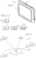
- the personal navigation device 10 includes a processing system 12, a location determining component 14, an antenna assembly 16 for the location determining component, a display 18, one or more input devices 20, a housing 22 which encloses and protects the other components from moisture, vibration, and impact, and other components described below.
- the antenna assembly 16 is configured and strategically mounted and positioned to optimize reception of external radio frequency signals while minimizing the overall size of the device 10 and eliminating protrusions from the housing 22 of the device 10.
- the processing system 12 may include any number of processors, controllers, or other processing systems and resident or external memory for storing data and other information accessed and/or generated by the device 10.
- the processing system 12 implements one or more software programs which control the display of information on the display 18 and input of information via the one or more input devices 20.
- the location determining component 14 comprises a global positioning system (GPS) receiver or any other device which can determine locations of the marine vessel in which the device 10 is used.
- GPS global positioning system
- FIG. 3 shows one representative view of a GPS denoted generally by reference numeral 23.
- a plurality of satellites 24 are in orbit about the Earth 26. The orbit of each satellite is not necessarily synchronous with the orbits of other satellites and, in fact, is likely asynchronous.
- a GPS receiver device 10 such as the ones described in connection with preferred embodiments of the present invention is shown receiving spread spectrum GPS satellite signals from the various satellites 24.
- the spread spectrum signals continuously transmitted from each satellite 24 utilize a highly accurate frequency standard accomplished with an extremely accurate atomic clock.
- the device 10 must acquire spread spectrum GPS satellite signals from at least three satellites for the GPS receiver device to calculate its two-dimensional position by triangulation.
- the location determining component 14 is operable to receive navigational signals from the GPS satellites 24 to calculate a position of the device 10 as a function of the signals.
- the location determining component 14 is also operable to calculate a route to a desired location, provide instructions to navigate to the desired location, display maps and other information on the display screen, and to execute other functions described herein.
- the location determining component 14 may include one or more processors, controllers, or other processing systems and memory or may utilize the components of the processing system 12.
- the memory of the processing system 12 and/or the location determining component 14 may store cartographic data and routing used by or generated by the location determining component 14.
- the memory may be integral with the location determining component 14, integral with the processing system 12, stand-alone memory, or a combination of both.
- the memory may include, for example, removable and non-removable memory elements such as RAM, ROM, flash (including microSD cards or the like), magnetic, optical, USB memory devices, and/or other conventional memory elements.
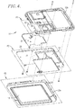
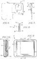
- the processing system 12 and the location determining component 14 may be mounted to a printed circuit board 28 in a conventional manner as depicted in FIGS. 4 through 7 .
- the circuit board is made of conventional materials and is sized to support all the components of the processing system 12, location determining component 14, and other electronics of the device 10.
- the display 18 is coupled with the processing system 12 and the location determining component 14 for displaying data and information as described herein.
- the display 18 may comprise an LCD (Liquid Crystal Diode), TFT (Thin Film Transistor) LCD, CRT (Cathode Ray Tube), LEP (Light Emitting Polymer or PLED (Polymer Light Emitting Diode), or the like, capable of displaying both text and graphical information.
- the display may be backlit such that it may be viewed in the dark or other low-light environments. As illustrated in FIGS. 1 , 9 and 10 , the display 18 is preferably positioned on a front face of the housing 22 for ease of viewing.
- the input devices 20 may also be positioned on the front surface of the housing 22 such that they may be easily accessed.
- the input devices 20 may include descriptive markings that identify their function.
- the inputs may be buttons, switches, keys, an electronic touch-screen associated with the display, voice recognition circuitry, or any other elements capable of controlling the processing system and location determining component.
- the housing 22 may be constructed from a suitable lightweight and impact-resistant material such as, for example, plastic, nylon, aluminum, or any combination thereof.
- the housing may include a front portion 22a and a rear portion 22b and may include one or more appropriate gaskets or seals to make it substantially waterproof or resistant.
- the housing 22 may also include a location for a rechargeable battery or other power source.
- the housing may take any suitable shape or size, and the particular size, weight and configuration of the housing may be changed without departing from the scope of the present invention.
- the antenna assembly 16 includes an antenna 30, a ground plane 32, and one or more shield fences (two shield fences 34a and 34b are illustrated), mounted to the circuit board 28.
- the antenna 30 may be a patch-type antenna such as those made by Inpaq Technology Co., Ltd.
- the patch antenna may be approximately square in shape and generally planar in construction having a thickness less than its length or width.
- the patch antenna 30 is approximately 25 mm x 25 mm square and 4 mm thick, but it may be formed in other sizes and shapes without departing from the scope of the present invention. Ideally, however, the patch antenna 30 is no thicker than about 8 mm.
- the patch antenna 30 may include a small diameter hole 36 near its center.
- One embodiment of the patch antenna has an output impedance of approximately 50 ohm and a center frequency of 1575.42 MHz.
- the ground plane 32 comprises a generally flat metal surface surrounding the antenna 30 for deflecting errant signals (i.e., multipath) reflected from the ground and other near-by objects.
- the ground plane 32 may be formed of approximately 0.2 mm to 0.3 mm thick cold rolled steel with a tin pre-plated coating and is approximately 50 mm x 50 mm square.
- the ground plane 32 may be made of other materials and formed in the other sizes and shapes without departing from the scope of the present invention.
- the ground plane 32 is formed with several perimeter notches.
- the shield fences 34a and 34b help to shield the antenna 30 and ground plane 32 from the circuit board 28 from electromagnetic fields.
- the shield fences 34a and 34b are also made of approximately 0.2 mm to 0.3 mm thick cold rolled steel with a tin pre-plated coating.
- one of the shield fences 34b is approximately 20 mm x 15 mm and approximately 1.75 mm tall, while the other 34a is approximately 29 x 34 mm and approximately 1.75 mm tall.
- the shield fences 34a and 34b may be made of other materials and formed in other sizes and shapes without departing from the scope of the present invention.
- only one shield fence or three or more shield fences may be used rather than two. Further, in exemplary embodiments, the shield fences 34a and 34b may be eliminated altogether.
- the antenna assembly 16 is mounted to the circuit board 28 by first attaching the two shield fences 34a and 34b to one face of the circuit board 28 as best illustrated in FIGS. 7, 8 and 10 .
- the shield fences 34a and 34b may be attached to the circuit board 28 using a suitable fastening technique, such as by adhesives, soldering, or the like.
- the ground plane 32 is then snapped onto the shield fences 34a and 34b or otherwise secured using a suitable fastening technique, such as by adhesives, soldering, or the like.
- the patch antenna 30 is secured to the exterior face of the ground plane 32 as illustrated.
- one face of the patch antenna 30 may be provided with a self-adhesive backing with a release layer.
- the release layer may be removed to expose the adhesive to secure the patch antenna 30 to the ground plane 32.
- a conductive post or pin 38 may then be inserted into the small diameter hole 36 in the patch antenna 30 and pushed through the circuit board 28 so that its distal end 40 extends from the face of the circuit board opposite the antenna assembly.
- the distal end 40 of the post or pin 38 may then be coupled with the GPS receiver or other location determining component of the device to transfer signals there between.
- the patch antenna 30 is entirely enclosed within the housing 22.
- the antenna 30 is positioned entirely within the outer perimeter edge of the circuit board 28 (i.e., so that the antenna 30 does not extend beyond an outer perimeter edge of the circuit board 28 in any direction).
- the ground plane 32 is positioned entirely within the outer perimeter edge of the circuit board 28 (i.e., so that the ground plane 32 does not extend beyond an outer perimeter edge of the circuit board 28 in any direction).
- the patch antenna 30 is positioned along a plane identified by P1 in FIGS. 4 and 5 . More specifically, the patch antenna 30 is positioned so that its surfaces are generally parallel to or co-planar with plane P1 and its edges are generally perpendicular to plane P1. Similarly, the housing 22 and the display 18 are positioned along a second plane identified by P2. Thus, as illustrated, plane P2 may be generally parallel to or coplanar with a front surface of the housing and/or the surface of the display 18 and generally perpendicular to the side or edge surfaces of the housing 22 (in embodiments of the device 10 where the edge surfaces of the housing 22 are generally perpendicular to the from or rear surfaces of the housing).
- the plane P2 may further/or alternatively be parallel with the rear surface of the housing 22.
- the circuit board 28 is positioned along a third plane identified by P3 so that one or both surfaces of the circuit board 28 are parallel to or coplanar with plane P3.
- the plane P1 along which the antenna 30 is positioned is generally parallel to the plane P2 which passes through the housing 22.
- the plane P1 is generally parallel to the plane P3 along which the circuit board is positioned.
- the plane P1 is parallel to both the planes P2 and P3.
- the antenna 30 may be positioned so that its surfaces are generally parallel to the circuit board, the front and/or rear surfaces of the housing 22, and/or the surface of the display.
- "generally parallel” and “generally perpendicular” are understood to encompass some deviations from parallel or perpendicular caused by manufacturing tolerances, normal shifting and re-positioning of components during use, and other similar causes.
- the antenna assembly 16 By configuring and mounting the antenna assembly 16 as described herein, reception of GPS signals is optimized while minimizing the overall size of the device 10 and eliminating protrusions from the housing 22. For example, by mounting the antenna 30 to a circuit board 28 which is positioned entirely within the housing, the personal navigation device 10 has no antenna protruding from its housing 22. In this manner, the housing may be made more esthetically pleasing (e.g., thinner, sleeker, etc.) than prior art devices which have antennas mounted on exterior surfaces of their housings.
- the housing 22 can be made thinner than known personal navigation devices in which the antennas are positioned generally perpendicular to their housings when the devices are in use, thus necessitating thicker housings and/or flip-type antennas.
- the invention is implemented with a personal navigation device 10 such as the one illustrated in FIG. 1 .
- a personal navigation device 10 such as the one illustrated in FIG. 1 .
- embodiments of the present invention can be implemented in various portable electronic devices.
- the personal navigation device 10 and its components illustrated and described herein are merely examples of a device and components that may be used to implement the embodiments of the present invention and may be replaced with other devices and components without departing from the scope of the invention.
- the device 10 may also include other components not specifically described but necessary or desirable for its function.
- the device 10 may include a speaker for providing audible instructions and feedback, a microphone for receiving voice commands, an infrared port for wirelessly receiving and transmitting data and other information from and to nearby electronics, and other information, and even a cellular or other radio transceiver for wirelessly receiving and transmitting data from and to remote devices.
- the radio transceiver may permit the device 10 to communicate with a remote server.
- the device 10 may further include a number of I/O ports that permit data and other information to be transferred to and from the processing system 12 and the location determining component 14.
- the I/O ports may include a memory card slot for receiving removable memory cards and a USB port for coupling with a USB cable connected to another processing system such as a personal computer.
- Navigational software, cartographic maps and other data and information may be loaded in the device 10 via the I/O ports, the wireless transceivers, or the infrared port.
Landscapes
- Engineering & Computer Science (AREA)
- Radar, Positioning & Navigation (AREA)
- Remote Sensing (AREA)
- Computer Networks & Wireless Communication (AREA)
- Physics & Mathematics (AREA)
- General Physics & Mathematics (AREA)
- Signal Processing (AREA)
- Automation & Control Theory (AREA)
- Position Fixing By Use Of Radio Waves (AREA)
Claims (2)
- Tragbare elektronische Vorrichtung, die aufweist:eine Ortbestimmungskomponente (14) zum Empfangen von Signalen von einer externen Quelle;ein mit der Ortbestimmungskomponente (14) verbundenes Verarbeitungssystem (12) zum Bestimmen eines Orts der tragbaren elektronischen Vorrichtung (10) als eine Funktion der Signale;eine mit dem Verarbeitungssystem (12) verbundene Anzeige (18) zum Anzeigen von Informationen, die sich auf den Ort der tragbaren elektronischen Vorrichtung (10) beziehen;ein Gehäuse (22), an dem die Anzeige (18) montiert ist und in dem die Ortbestimmungskomponente (14) und das Verarbeitungssystem (12) aufgenommen sind;ein Leiterplatte (28), die in dem Gehäuse (22) enthalten ist und auf der die Ortbestimmungskomponente (14) und das Verarbeitungssystem (12) montiert sind; undeine mit der Standortbestimmungskomponente (14) verbundene Antenne (30) zum Unterstützen bei einem Empfang der Signale,wobei die Antenne (30) in dem Gehäuse (22) fest entlang einer Ebene angeordnet ist, die im Allgemeinen parallel zu einer vorderen Fläche des Gehäuses (22) ist,wobei die Ebene, entlang welcher die Antenne (30) angeordnet ist, im Allgemeinen parallel zu einer Ebene ist, in der die Leiterplatte (28) angeordnet ist, und wobei die Ebene, entlang welcher die Antenne (30) angeordnet ist, im Allgemeinen parallel zu einer Ebene ist, entlang welcher die Anzeige (18) angeordnet ist,dadurch gekennzeichnet, dass die Antenne (30) an der Leiterplatte (28) auf einer Seite montiert ist, die entgegengesetzt ist zu einer Seite, die der Ebene, entlang welcher die Anzeige (18) angeordnet ist, zugewandt ist, und dadurch, dass die tragbare elektronische Vorrichtung ferner eine Masseebene (32), die zwischen der Antenne (30) und der Leiterplatte (28) angeordnet ist, und eine Abschirmung (34a, 34b) aufweist, die zumindest teilweise zwischen der Masseebene (32) und der Leiterplatte (28) angeordnet ist.
- Tragbare elektronische Vorrichtung nach Anspruch 1, bei der die Antenne (30) eine Patch-Antenne ist, die eine Dicke von etwa 2 mm bis 6 mm aufweist.
Applications Claiming Priority (3)
| Application Number | Priority Date | Filing Date | Title |
|---|---|---|---|
| US89309107P | 2007-03-05 | 2007-03-05 | |
| US11/685,399 US7538723B2 (en) | 2007-03-05 | 2007-03-13 | Personal navigation device with improved antenna mounting configuration |
| PCT/US2008/050668 WO2008109191A1 (en) | 2007-03-05 | 2008-01-09 | Personal navigation device with improved antenna mounting configuration |
Publications (3)
| Publication Number | Publication Date |
|---|---|
| EP2115389A1 EP2115389A1 (de) | 2009-11-11 |
| EP2115389A4 EP2115389A4 (de) | 2014-06-25 |
| EP2115389B1 true EP2115389B1 (de) | 2019-06-19 |
Family
ID=39738653
Family Applications (1)
| Application Number | Title | Priority Date | Filing Date |
|---|---|---|---|
| EP08713680.0A Active EP2115389B1 (de) | 2007-03-05 | 2008-01-09 | Persönliches navigationsgerät mit einer verbesserten antennenanbringkonfiguration |
Country Status (3)
| Country | Link |
|---|---|
| US (1) | US7538723B2 (de) |
| EP (1) | EP2115389B1 (de) |
| WO (1) | WO2008109191A1 (de) |
Families Citing this family (14)
| Publication number | Priority date | Publication date | Assignee | Title |
|---|---|---|---|---|
| JP4960153B2 (ja) * | 2007-06-19 | 2012-06-27 | 株式会社東芝 | 電子機器 |
| EP2166825A1 (de) * | 2008-09-17 | 2010-03-24 | Vincotech Holdings S.a.r.l. | Lötbares elektronisches Modul mit Schaltungsträger |
| USD611363S1 (en) * | 2009-02-26 | 2010-03-09 | Garmin Ltd. | Navigation device |
| TWD139984S1 (zh) * | 2009-08-27 | 2011-04-11 | 湯姆湯姆國際股份有限公司 | 結合外殼及安裝架之導航機 |
| AU328126S (en) * | 2009-08-27 | 2009-10-23 | Tomtom Int Bv | Casing for electronic device |
| UY3889Q (es) * | 2009-08-27 | 2010-09-30 | Tomtom Int Bv | Sistemas de navegacion 1 |
| JP5556101B2 (ja) * | 2009-09-17 | 2014-07-23 | ソニー株式会社 | 方位算出装置、補正値初期化方法及び方位算出機能付携帯電話機 |
| DE102011013667A1 (de) | 2010-12-20 | 2012-06-21 | Continental Automotive Gmbh | Bordinformationssystem mit Antenne zum Empfang satellitenbasierter Geopositionsdaten |
| USD659563S1 (en) * | 2011-03-22 | 2012-05-15 | Garmin Switzerland Gmbh | Electronic device |
| USD659562S1 (en) * | 2011-03-22 | 2012-05-15 | Garmin Switzerland Gmbh | Electronic device |
| USD659565S1 (en) * | 2011-03-24 | 2012-05-15 | Garmin Switzerland Gmbh | Electronic device |
| US8698680B2 (en) | 2012-01-17 | 2014-04-15 | Garmin Switzerland Gmbh | Watch with improved ground plane |
| USD818040S1 (en) * | 2016-02-11 | 2018-05-15 | Dover Europe Sàrl | Display device for a printing machine |
| US12429335B2 (en) | 2020-12-02 | 2025-09-30 | The Boeing Company | Personal navigation device operable in GNSS-denied environment |
Family Cites Families (12)
| Publication number | Priority date | Publication date | Assignee | Title |
|---|---|---|---|---|
| JPH09145814A (ja) * | 1995-11-21 | 1997-06-06 | Harada Ind Co Ltd | 携帯形gps測位表示装置 |
| JPH11311666A (ja) * | 1998-02-23 | 1999-11-09 | Whitaker Corp:The | Gps受信機 |
| US6128515A (en) * | 1998-02-27 | 2000-10-03 | Garmin Corporation | Combined global positioning and wireless telephone device |
| US6522291B1 (en) | 1999-12-10 | 2003-02-18 | Matsushita Electric Works, Ltd. | GPS receiver sharing an antenna ground plane with an EMI shield |
| JP3558023B2 (ja) * | 2000-08-29 | 2004-08-25 | セイコーエプソン株式会社 | 携帯型情報端末 |
| SE523191C2 (sv) * | 2000-09-25 | 2004-03-30 | Ericsson Telefon Ab L M | En portabel kommunikationsapparat med en första och en andra antenn varvid den första antennens strålande del är integrerad med en display i en flerskiktsstruktur |
| US20020133293A1 (en) * | 2001-03-16 | 2002-09-19 | Howard Goldman, Inc | Concealable portable GPS communication system |
| US7299129B2 (en) * | 2002-04-02 | 2007-11-20 | Garmin Ltd. | Portable navigation device with releasable antenna |
| US6795770B1 (en) * | 2002-04-02 | 2004-09-21 | Garmin Ltd. | Portable navigation device with instant on configuration on navigational display |
| US20060229810A1 (en) * | 2005-04-11 | 2006-10-12 | John Cross | GPS device and method for displaying weather data |
| DE102005038300A1 (de) * | 2005-08-12 | 2007-02-15 | Royaltek Company Ltd. | Navigationsvorrichtung mit GPS und TMC und Verfahren davon |
| US7366609B2 (en) | 2005-08-29 | 2008-04-29 | Garmin Ltd. | Navigation device with control feature limiting access to non-navigation application |
-
2007
- 2007-03-13 US US11/685,399 patent/US7538723B2/en active Active
-
2008
- 2008-01-09 WO PCT/US2008/050668 patent/WO2008109191A1/en not_active Ceased
- 2008-01-09 EP EP08713680.0A patent/EP2115389B1/de active Active
Non-Patent Citations (1)
| Title |
|---|
| None * |
Also Published As
| Publication number | Publication date |
|---|---|
| US20080218408A1 (en) | 2008-09-11 |
| EP2115389A4 (de) | 2014-06-25 |
| WO2008109191A1 (en) | 2008-09-12 |
| EP2115389A1 (de) | 2009-11-11 |
| US7538723B2 (en) | 2009-05-26 |
Similar Documents
| Publication | Publication Date | Title |
|---|---|---|
| EP2115389B1 (de) | Persönliches navigationsgerät mit einer verbesserten antennenanbringkonfiguration | |
| US10209342B2 (en) | Electromagnetic radiation source locating system | |
| US7271774B2 (en) | Electronic wearable device | |
| US20210325202A1 (en) | Tracking Systems for Electronic Devices | |
| US6774843B2 (en) | Method for acquiring azimuth information | |
| US5910882A (en) | Portable electronic device for use in combination portable and fixed mount applications | |
| US6509867B1 (en) | Article tracking device | |
| US8717232B2 (en) | Handheld global positioning system device | |
| US7034747B1 (en) | System and method for wirelessly linking a GPS device and a portable electronic device | |
| US7436362B2 (en) | Antenna device | |
| EP1378960A1 (de) | Mobilfunkgerät | |
| US20150109172A1 (en) | Antenna built-in portable device | |
| US7590433B2 (en) | Portable electronic device | |
| JPH10197662A (ja) | 受信装置 | |
| JP2012500395A (ja) | 方角を指し示すカード | |
| US7193569B2 (en) | Double-layer antenna structure for hand-held devices | |
| US20210314493A1 (en) | Location Systems for Electronic Device Interactions with Environment | |
| WO2008075156A1 (en) | Antenna for a portable device | |
| US20170149129A1 (en) | Antenna alignment device and methods for aligning antennas | |
| EP1519440A1 (de) | Antennenvorrichtung | |
| US20070060072A1 (en) | Portable electronic device | |
| US11402459B2 (en) | Distributed radio signal targeting device | |
| CN101663562A (zh) | 具有改进的天线安装配置的个人导航装置 | |
| US6970728B2 (en) | Extended antenna support for a wireless communications device | |
| US12046918B2 (en) | Recovery units for non-proximity wireless power transfer |
Legal Events
| Date | Code | Title | Description |
|---|---|---|---|
| PUAI | Public reference made under article 153(3) epc to a published international application that has entered the european phase |
Free format text: ORIGINAL CODE: 0009012 |
|
| 17P | Request for examination filed |
Effective date: 20090821 |
|
| AK | Designated contracting states |
Kind code of ref document: A1 Designated state(s): AT BE BG CH CY CZ DE DK EE ES FI FR GB GR HR HU IE IS IT LI LT LU LV MC MT NL NO PL PT RO SE SI SK TR |
|
| DAX | Request for extension of the european patent (deleted) | ||
| RAP1 | Party data changed (applicant data changed or rights of an application transferred) |
Owner name: GARMIN SWITZERLAND GMBH |
|
| A4 | Supplementary search report drawn up and despatched |
Effective date: 20140522 |
|
| RIC1 | Information provided on ipc code assigned before grant |
Ipc: H01Q 1/24 20060101ALI20140516BHEP Ipc: G01C 21/26 20060101AFI20140516BHEP Ipc: G01S 19/35 20100101ALI20140516BHEP |
|
| 17Q | First examination report despatched |
Effective date: 20160714 |
|
| STAA | Information on the status of an ep patent application or granted ep patent |
Free format text: STATUS: EXAMINATION IS IN PROGRESS |
|
| GRAP | Despatch of communication of intention to grant a patent |
Free format text: ORIGINAL CODE: EPIDOSNIGR1 |
|
| STAA | Information on the status of an ep patent application or granted ep patent |
Free format text: STATUS: GRANT OF PATENT IS INTENDED |
|
| INTG | Intention to grant announced |
Effective date: 20190103 |
|
| RIC1 | Information provided on ipc code assigned before grant |
Ipc: G01S 19/35 20100101ALI20140516BHEP Ipc: H01Q 1/24 20060101ALI20140516BHEP Ipc: G01C 21/26 20060101AFI20140516BHEP |
|
| GRAS | Grant fee paid |
Free format text: ORIGINAL CODE: EPIDOSNIGR3 |
|
| GRAA | (expected) grant |
Free format text: ORIGINAL CODE: 0009210 |
|
| STAA | Information on the status of an ep patent application or granted ep patent |
Free format text: STATUS: THE PATENT HAS BEEN GRANTED |
|
| AK | Designated contracting states |
Kind code of ref document: B1 Designated state(s): AT BE BG CH CY CZ DE DK EE ES FI FR GB GR HR HU IE IS IT LI LT LU LV MC MT NL NO PL PT RO SE SI SK TR |
|
| REG | Reference to a national code |
Ref country code: GB Ref legal event code: FG4D |
|
| REG | Reference to a national code |
Ref country code: CH Ref legal event code: EP |
|
| REG | Reference to a national code |
Ref country code: IE Ref legal event code: FG4D |
|
| REG | Reference to a national code |
Ref country code: DE Ref legal event code: R096 Ref document number: 602008060423 Country of ref document: DE |
|
| REG | Reference to a national code |
Ref country code: AT Ref legal event code: REF Ref document number: 1146093 Country of ref document: AT Kind code of ref document: T Effective date: 20190715 |
|
| REG | Reference to a national code |
Ref country code: NL Ref legal event code: MP Effective date: 20190619 |
|
| PG25 | Lapsed in a contracting state [announced via postgrant information from national office to epo] |
Ref country code: FI Free format text: LAPSE BECAUSE OF FAILURE TO SUBMIT A TRANSLATION OF THE DESCRIPTION OR TO PAY THE FEE WITHIN THE PRESCRIBED TIME-LIMIT Effective date: 20190619 Ref country code: LT Free format text: LAPSE BECAUSE OF FAILURE TO SUBMIT A TRANSLATION OF THE DESCRIPTION OR TO PAY THE FEE WITHIN THE PRESCRIBED TIME-LIMIT Effective date: 20190619 Ref country code: SE Free format text: LAPSE BECAUSE OF FAILURE TO SUBMIT A TRANSLATION OF THE DESCRIPTION OR TO PAY THE FEE WITHIN THE PRESCRIBED TIME-LIMIT Effective date: 20190619 Ref country code: HR Free format text: LAPSE BECAUSE OF FAILURE TO SUBMIT A TRANSLATION OF THE DESCRIPTION OR TO PAY THE FEE WITHIN THE PRESCRIBED TIME-LIMIT Effective date: 20190619 Ref country code: NO Free format text: LAPSE BECAUSE OF FAILURE TO SUBMIT A TRANSLATION OF THE DESCRIPTION OR TO PAY THE FEE WITHIN THE PRESCRIBED TIME-LIMIT Effective date: 20190919 |
|
| REG | Reference to a national code |
Ref country code: LT Ref legal event code: MG4D |
|
| PG25 | Lapsed in a contracting state [announced via postgrant information from national office to epo] |
Ref country code: LV Free format text: LAPSE BECAUSE OF FAILURE TO SUBMIT A TRANSLATION OF THE DESCRIPTION OR TO PAY THE FEE WITHIN THE PRESCRIBED TIME-LIMIT Effective date: 20190619 Ref country code: GR Free format text: LAPSE BECAUSE OF FAILURE TO SUBMIT A TRANSLATION OF THE DESCRIPTION OR TO PAY THE FEE WITHIN THE PRESCRIBED TIME-LIMIT Effective date: 20190920 Ref country code: BG Free format text: LAPSE BECAUSE OF FAILURE TO SUBMIT A TRANSLATION OF THE DESCRIPTION OR TO PAY THE FEE WITHIN THE PRESCRIBED TIME-LIMIT Effective date: 20190919 |
|
| REG | Reference to a national code |
Ref country code: AT Ref legal event code: MK05 Ref document number: 1146093 Country of ref document: AT Kind code of ref document: T Effective date: 20190619 |
|
| PG25 | Lapsed in a contracting state [announced via postgrant information from national office to epo] |
Ref country code: SK Free format text: LAPSE BECAUSE OF FAILURE TO SUBMIT A TRANSLATION OF THE DESCRIPTION OR TO PAY THE FEE WITHIN THE PRESCRIBED TIME-LIMIT Effective date: 20190619 Ref country code: EE Free format text: LAPSE BECAUSE OF FAILURE TO SUBMIT A TRANSLATION OF THE DESCRIPTION OR TO PAY THE FEE WITHIN THE PRESCRIBED TIME-LIMIT Effective date: 20190619 Ref country code: CZ Free format text: LAPSE BECAUSE OF FAILURE TO SUBMIT A TRANSLATION OF THE DESCRIPTION OR TO PAY THE FEE WITHIN THE PRESCRIBED TIME-LIMIT Effective date: 20190619 Ref country code: NL Free format text: LAPSE BECAUSE OF FAILURE TO SUBMIT A TRANSLATION OF THE DESCRIPTION OR TO PAY THE FEE WITHIN THE PRESCRIBED TIME-LIMIT Effective date: 20190619 Ref country code: RO Free format text: LAPSE BECAUSE OF FAILURE TO SUBMIT A TRANSLATION OF THE DESCRIPTION OR TO PAY THE FEE WITHIN THE PRESCRIBED TIME-LIMIT Effective date: 20190619 Ref country code: AT Free format text: LAPSE BECAUSE OF FAILURE TO SUBMIT A TRANSLATION OF THE DESCRIPTION OR TO PAY THE FEE WITHIN THE PRESCRIBED TIME-LIMIT Effective date: 20190619 Ref country code: PT Free format text: LAPSE BECAUSE OF FAILURE TO SUBMIT A TRANSLATION OF THE DESCRIPTION OR TO PAY THE FEE WITHIN THE PRESCRIBED TIME-LIMIT Effective date: 20191021 |
|
| PG25 | Lapsed in a contracting state [announced via postgrant information from national office to epo] |
Ref country code: IT Free format text: LAPSE BECAUSE OF FAILURE TO SUBMIT A TRANSLATION OF THE DESCRIPTION OR TO PAY THE FEE WITHIN THE PRESCRIBED TIME-LIMIT Effective date: 20190619 Ref country code: IS Free format text: LAPSE BECAUSE OF FAILURE TO SUBMIT A TRANSLATION OF THE DESCRIPTION OR TO PAY THE FEE WITHIN THE PRESCRIBED TIME-LIMIT Effective date: 20191019 Ref country code: ES Free format text: LAPSE BECAUSE OF FAILURE TO SUBMIT A TRANSLATION OF THE DESCRIPTION OR TO PAY THE FEE WITHIN THE PRESCRIBED TIME-LIMIT Effective date: 20190619 |
|
| PG25 | Lapsed in a contracting state [announced via postgrant information from national office to epo] |
Ref country code: TR Free format text: LAPSE BECAUSE OF FAILURE TO SUBMIT A TRANSLATION OF THE DESCRIPTION OR TO PAY THE FEE WITHIN THE PRESCRIBED TIME-LIMIT Effective date: 20190619 |
|
| PG25 | Lapsed in a contracting state [announced via postgrant information from national office to epo] |
Ref country code: PL Free format text: LAPSE BECAUSE OF FAILURE TO SUBMIT A TRANSLATION OF THE DESCRIPTION OR TO PAY THE FEE WITHIN THE PRESCRIBED TIME-LIMIT Effective date: 20190619 Ref country code: DK Free format text: LAPSE BECAUSE OF FAILURE TO SUBMIT A TRANSLATION OF THE DESCRIPTION OR TO PAY THE FEE WITHIN THE PRESCRIBED TIME-LIMIT Effective date: 20190619 |
|
| PG25 | Lapsed in a contracting state [announced via postgrant information from national office to epo] |
Ref country code: IS Free format text: LAPSE BECAUSE OF FAILURE TO SUBMIT A TRANSLATION OF THE DESCRIPTION OR TO PAY THE FEE WITHIN THE PRESCRIBED TIME-LIMIT Effective date: 20200224 |
|
| REG | Reference to a national code |
Ref country code: DE Ref legal event code: R097 Ref document number: 602008060423 Country of ref document: DE |
|
| PLBE | No opposition filed within time limit |
Free format text: ORIGINAL CODE: 0009261 |
|
| STAA | Information on the status of an ep patent application or granted ep patent |
Free format text: STATUS: NO OPPOSITION FILED WITHIN TIME LIMIT |
|
| PG2D | Information on lapse in contracting state deleted |
Ref country code: IS |
|
| 26N | No opposition filed |
Effective date: 20200603 |
|
| PG25 | Lapsed in a contracting state [announced via postgrant information from national office to epo] |
Ref country code: SI Free format text: LAPSE BECAUSE OF FAILURE TO SUBMIT A TRANSLATION OF THE DESCRIPTION OR TO PAY THE FEE WITHIN THE PRESCRIBED TIME-LIMIT Effective date: 20190619 Ref country code: MC Free format text: LAPSE BECAUSE OF FAILURE TO SUBMIT A TRANSLATION OF THE DESCRIPTION OR TO PAY THE FEE WITHIN THE PRESCRIBED TIME-LIMIT Effective date: 20190619 |
|
| REG | Reference to a national code |
Ref country code: CH Ref legal event code: PL |
|
| REG | Reference to a national code |
Ref country code: BE Ref legal event code: MM Effective date: 20200131 |
|
| PG25 | Lapsed in a contracting state [announced via postgrant information from national office to epo] |
Ref country code: LU Free format text: LAPSE BECAUSE OF NON-PAYMENT OF DUE FEES Effective date: 20200109 |
|
| PG25 | Lapsed in a contracting state [announced via postgrant information from national office to epo] |
Ref country code: CH Free format text: LAPSE BECAUSE OF NON-PAYMENT OF DUE FEES Effective date: 20200131 Ref country code: LI Free format text: LAPSE BECAUSE OF NON-PAYMENT OF DUE FEES Effective date: 20200131 Ref country code: BE Free format text: LAPSE BECAUSE OF NON-PAYMENT OF DUE FEES Effective date: 20200131 |
|
| PG25 | Lapsed in a contracting state [announced via postgrant information from national office to epo] |
Ref country code: IE Free format text: LAPSE BECAUSE OF NON-PAYMENT OF DUE FEES Effective date: 20200109 |
|
| PG25 | Lapsed in a contracting state [announced via postgrant information from national office to epo] |
Ref country code: MT Free format text: LAPSE BECAUSE OF FAILURE TO SUBMIT A TRANSLATION OF THE DESCRIPTION OR TO PAY THE FEE WITHIN THE PRESCRIBED TIME-LIMIT Effective date: 20190619 Ref country code: CY Free format text: LAPSE BECAUSE OF FAILURE TO SUBMIT A TRANSLATION OF THE DESCRIPTION OR TO PAY THE FEE WITHIN THE PRESCRIBED TIME-LIMIT Effective date: 20190619 |
|
| PGFP | Annual fee paid to national office [announced via postgrant information from national office to epo] |
Ref country code: DE Payment date: 20250120 Year of fee payment: 18 |
|
| PGFP | Annual fee paid to national office [announced via postgrant information from national office to epo] |
Ref country code: FR Payment date: 20250123 Year of fee payment: 18 |
|
| PGFP | Annual fee paid to national office [announced via postgrant information from national office to epo] |
Ref country code: GB Payment date: 20250123 Year of fee payment: 18 |