EP2114796B1 - Pocket sized fluid dispenser - Google Patents
Pocket sized fluid dispenser Download PDFInfo
- Publication number
- EP2114796B1 EP2114796B1 EP08701578A EP08701578A EP2114796B1 EP 2114796 B1 EP2114796 B1 EP 2114796B1 EP 08701578 A EP08701578 A EP 08701578A EP 08701578 A EP08701578 A EP 08701578A EP 2114796 B1 EP2114796 B1 EP 2114796B1
- Authority
- EP
- European Patent Office
- Prior art keywords
- container
- dispenser
- actuator button
- intermediate ring
- valve stem
- Prior art date
- Legal status (The legal status is an assumption and is not a legal conclusion. Google has not performed a legal analysis and makes no representation as to the accuracy of the status listed.)
- Not-in-force
Links
Images




Classifications
-
- A—HUMAN NECESSITIES
- A45—HAND OR TRAVELLING ARTICLES
- A45D—HAIRDRESSING OR SHAVING EQUIPMENT; EQUIPMENT FOR COSMETICS OR COSMETIC TREATMENTS, e.g. FOR MANICURING OR PEDICURING
- A45D34/00—Containers or accessories specially adapted for handling liquid toiletry or cosmetic substances, e.g. perfumes
- A45D34/04—Appliances specially adapted for applying liquid, e.g. using roller or ball
-
- B—PERFORMING OPERATIONS; TRANSPORTING
- B65—CONVEYING; PACKING; STORING; HANDLING THIN OR FILAMENTARY MATERIAL
- B65D—CONTAINERS FOR STORAGE OR TRANSPORT OF ARTICLES OR MATERIALS, e.g. BAGS, BARRELS, BOTTLES, BOXES, CANS, CARTONS, CRATES, DRUMS, JARS, TANKS, HOPPERS, FORWARDING CONTAINERS; ACCESSORIES, CLOSURES, OR FITTINGS THEREFOR; PACKAGING ELEMENTS; PACKAGES
- B65D83/00—Containers or packages with special means for dispensing contents
- B65D83/14—Containers for dispensing liquid or semi-liquid contents by internal gaseous pressure, i.e. aerosol containers comprising propellant
- B65D83/16—Actuating means
- B65D83/162—Push button actuators
-
- B—PERFORMING OPERATIONS; TRANSPORTING
- B65—CONVEYING; PACKING; STORING; HANDLING THIN OR FILAMENTARY MATERIAL
- B65D—CONTAINERS FOR STORAGE OR TRANSPORT OF ARTICLES OR MATERIALS, e.g. BAGS, BARRELS, BOTTLES, BOXES, CANS, CARTONS, CRATES, DRUMS, JARS, TANKS, HOPPERS, FORWARDING CONTAINERS; ACCESSORIES, CLOSURES, OR FITTINGS THEREFOR; PACKAGING ELEMENTS; PACKAGES
- B65D83/00—Containers or packages with special means for dispensing contents
- B65D83/14—Containers for dispensing liquid or semi-liquid contents by internal gaseous pressure, i.e. aerosol containers comprising propellant
- B65D83/16—Actuating means
- B65D83/22—Actuating means with means to disable actuation
-
- B—PERFORMING OPERATIONS; TRANSPORTING
- B65—CONVEYING; PACKING; STORING; HANDLING THIN OR FILAMENTARY MATERIAL
- B65D—CONTAINERS FOR STORAGE OR TRANSPORT OF ARTICLES OR MATERIALS, e.g. BAGS, BARRELS, BOTTLES, BOXES, CANS, CARTONS, CRATES, DRUMS, JARS, TANKS, HOPPERS, FORWARDING CONTAINERS; ACCESSORIES, CLOSURES, OR FITTINGS THEREFOR; PACKAGING ELEMENTS; PACKAGES
- B65D83/00—Containers or packages with special means for dispensing contents
- B65D83/14—Containers for dispensing liquid or semi-liquid contents by internal gaseous pressure, i.e. aerosol containers comprising propellant
- B65D83/38—Details of the container body
-
- B—PERFORMING OPERATIONS; TRANSPORTING
- B65—CONVEYING; PACKING; STORING; HANDLING THIN OR FILAMENTARY MATERIAL
- B65D—CONTAINERS FOR STORAGE OR TRANSPORT OF ARTICLES OR MATERIALS, e.g. BAGS, BARRELS, BOTTLES, BOXES, CANS, CARTONS, CRATES, DRUMS, JARS, TANKS, HOPPERS, FORWARDING CONTAINERS; ACCESSORIES, CLOSURES, OR FITTINGS THEREFOR; PACKAGING ELEMENTS; PACKAGES
- B65D83/00—Containers or packages with special means for dispensing contents
- B65D83/14—Containers for dispensing liquid or semi-liquid contents by internal gaseous pressure, i.e. aerosol containers comprising propellant
- B65D83/44—Valves specially adapted for the discharge of contents; Regulating devices
- B65D83/48—Lift valves, e.g. operated by push action
-
- A—HUMAN NECESSITIES
- A45—HAND OR TRAVELLING ARTICLES
- A45D—HAIRDRESSING OR SHAVING EQUIPMENT; EQUIPMENT FOR COSMETICS OR COSMETIC TREATMENTS, e.g. FOR MANICURING OR PEDICURING
- A45D2200/00—Details not otherwise provided for in A45D
- A45D2200/05—Details of containers
- A45D2200/054—Means for supplying liquid to the outlet of the container
- A45D2200/057—Spray nozzles; Generating atomised liquid
-
- A—HUMAN NECESSITIES
- A45—HAND OR TRAVELLING ARTICLES
- A45D—HAIRDRESSING OR SHAVING EQUIPMENT; EQUIPMENT FOR COSMETICS OR COSMETIC TREATMENTS, e.g. FOR MANICURING OR PEDICURING
- A45D34/00—Containers or accessories specially adapted for handling liquid toiletry or cosmetic substances, e.g. perfumes
- A45D34/02—Scent flasks, e.g. with evaporator
Definitions
- Body odour as well as other unpleasant odours from cigarette smoke, food, etc., can be embarrassing in certain situations. For young people, especially adolescent males, these unpleasant odours can be very embarrassing.
- a liquid cosmetic product such as perfume or cologne, can be applied to overcome and/or eliminate these unpleasant odours. Aerosol dispensers are particularly useful to dispense liquid cosmetic products, e.g. antiperspirant, deodorant and fragrance products, quickly and evenly over a person's body.
- US 3, 426, 948 A discloses an actuator for a foam dispenser, said actuator having a valve button, a valve button locking and a valve collar.
- FR 2, 569, 581 discloses a dispensing assembly comprising a container, a movable actuator button and a locking ring for locking the actuator button.
- a dispenser according to claim 1 that can allow a person to quickly and unobtrusively apply liquid cosmetic product includes a palm sized dispenser and the liquid cosmetic product is disposed in the dispenser under pressure that is greater than atmospheric pressure.
- the dispenser includes a movable actuator button for controlling dispensing of the liquid cosmetic product from the dispenser and a locking mechanism for locking the actuator button.
- a dispenser 10 contains a liquid cosmetic product, which can include hair spray, body spray, deodorant, antiperspirant and fragrances such as perfume and cologne.
- the dispenser 10 contains the liquid cosmetic composition under pressure, i.e. a pressure that is greater than atmospheric pressure, similar to a known aerosol container so that the liquid cosmetic product can be quickly dispensed from the dispenser.
- the dispenser 10 can be appropriately shaped and sized so it is discretely concealed in a person's palm and can be concealed or substantially completely concealed in a closed fist. Because of the small size of the dispenser 10, it also fits conveniently into a clothing pocket.
- the dispenser has a diameter up to about 2.5 cm, more particularly, from about 1 cm to about 2.5 cm, and a height less than about 9 cm, more particularly, from about 7 cm to about 8 cm.
- the dispenser has a diameter of from about 1.5 cm to about 2 cm, and a height of from about 7 cm to about 8 cm.
- the hand H shown in FIGURE 2 is meant to depict a typical teenage boy's hand having a palm breadth PB of about 7 cm to about 9 cm and a first finger length of about 10 cm to about 14 cm.
- the dispenser 10 is discretely concealed in the person's palm and can be dispensed quickly to cover up or eliminate embarrassing odours.
- the first finger can be moved to allow the liquid cosmetic product to exit the dispenser and the thumb can be used to operate the dispenser.
- the dispenser 10 includes a container 12 and an actuator assembly 14.
- the container and the actuator assembly are attached to one another and form a single unit that is disposed or recycled once the liquid cosmetic product has been dispensed from the dispenser.
- the container 12 includes a chamber that holds the liquid cosmetic product that is to be dispensed.
- the container 12 has an internal free volume of less than about 60 mL.
- the container has an internal free volume of from about 5 mL to about 40 mL.
- the container has an internal free volume of from about 5 mL to about 20 mL.
- the container has an internal free volume of from about 6 mL to about 15 mL, more particularly, from about 6 mL and about 10 mL.
- the container has an internal free volume of about 8.5 mL.
- the container is cylindrical in shape, similar to a conventional aerosol can, but can take other configurations without departing from the scope of the invention.
- the container has a diameter of up to about about 20 mm. In another embodiment the container has a diameter of from about 10 to about 20 mm, more particularly from about 10 to about 15 mm. In yet another embodiment, the diameter is about 15 mm.
- the container 12 connects to and is selectively opened and closed by the actuator assembly 14.
- the container is cylindrical with an open top and in the depicted embodiment is made from aluminum. Other materials can be used. Where the liquid cosmetic product is to be held under pressure, the other materials should be able to withstand the pressure at which the liquid cosmetic product will be held.
- a valve cup 18 that forms part of a valve assembly 22 connects to and covers the container (the container 12 is not shown in FIGURE 3 ).
- the valve cup 18 fits onto the container and is also made of aluminum.
- the valve cup 18 has a diameter at its uppermost end that, in one embodiment, is less than about 20 mm and preferably less than about 15 mm.
- the valve cup 18 crimps on to the container 16 via an external crimping action that reduces the diameter of the container and the valve cup at the crimped portion to a diameter that, in one embodiment, is from about 10 to about 12 mm, more particularly, from about 11.2 mm to about 11.7 mm.
- the crimp depth is from about 4 to about 6 mm, more particularly from about 4.4 to about 5.3 mm.
- the valve cup 18 includes an opening 24 through which a valve stem 26 of the valve assembly extends.
- the valve assembly 22 selectively opens and closes to provide selective dispensing of the liquid cosmetic product stored in the container.
- the valve assembly 22 includes a valve stem 26 that extends through the opening 24 in the valve cup 18.
- An annular seal 28 surrounds the valve stem 26.
- a biasing member such as a spring 32, biases the valve stem 26 upwardly (as per the orientation depicted in FIGURE 3 ) towards a closed position which is shown in FIGURE 3 .
- the biasing member 32 is seated in and acts against a valve seat 34.
- the annular seal 28 is pressed against an upper inner surface of the cap 18 by the valve seat 34.
- a second, lower annular seal 36 surrounds the valve seat 34 and abuts an inner cylindrical surface of the container 12 (not depicted in FIGURE 3 ).
- the container 12 is sandwiched between the valve cup 18 and the valve seat 34 so that these components are fixed in relation to one another.
- the valve seat 34 defines a valve chamber 38 that receives the spring 32 and a lower portion of the valve stem 26.
- the valve seat 34 also defines a dip tube chamber 42 that snuggly receives a dip tube 44 that extends into the container 12 ( FIGURE 1 ) holding the liquid cosmetic product.
- the dip tube 42 is in communication with the valve chamber 38 via a passage 46.
- valve stem 26 To dispense product from the container 16, the valve stem 26 is moved towards the valve seat 34 and acts against the biasing force of the spring 32 to open the valve assembly 22. A radial opening 52 formed in the valve stem 26 is blocked by the annular seal 28 when the valve stem is biased to the closed position as shown in FIGURE 3 .
- the radial passage 52 which is in communication with an axial passage 54, also communicates with the valve chamber 38, which is under pressure, and the valve chamber is in communication with the dip tube 42 via the passage 46.
- the actuator assembly 14 includes an actuator button 60 that selectively moves the valve stem 26 to dispense the liquid cosmetic product.
- the actuator assembly 14 connects to the container 12 and is "capless" for quick actuation. Because the actuator assembly is capless, i.e. a cap is not removed from the dispenser prior to dispensing product, a locking mechanism is provided to inhibit accidental dispensing of the liquid cosmetic product from the dispenser.
- the actuator assembly 14 in the depicted embodiment includes the actuator button 60, an intermediate ring 62 and a locking ring 64. Because of the small size the user of the dispenser can operate, lock and unlock the dispenser using only one hand if desired. In the depicted embodiment, the locking mechanism is located with respect to the actuator to facilitate one handed operation.
- the actuator button 60 is movable to move the valve stem 26 against the biasing force of the spring 32.
- the actuator button 60 in the depicted embodiment is generally cylindrical having a closed end and an open end. In the depicted embodiment the actuator button is made from a molded plastic, but other materials and methods of manufacture can be used.
- the actuator button 60 includes a generally cylindrical outer wall 66 depending from an upper platform 68 and a stem socket 72 that is radially spaced from the outer wall and depends from the upper platform 68.
- An annular gap 74 is disposed between the outer wall 66 and the stem socket 72, and as seen in FIGURE 3 a portion of the intermediate ring 62 resides in this gap 74 when the actuator assembly 14 is finally assembled and attached to the container 12.
- the actuator button 60 directly connects to the valve stem 26.
- a passage 76 is formed in the stem socket 72.
- the passage includes a lower counterbore 78 that receives the valve stem 26 and a chamfer 82 to facilitate alignment and connection of the actuator button 60 to the valve stem 26.
- the valve stem 26 includes an annular protuberance 84 that radially extends from the outer cylindrical surface of the valve stem 26 and engages with the inner cylindrical surface of the couterbore 78.
- the outer diameter of the valve stem 26 at the protuberance 84 is slightly larger than the diameter of the counterbore 78 to provide a friction fit between the actuator button 60 and the valve stem 26 so that removal of the actuator button 60 from the valve stem 26 is difficult.
- the protuberance 84 and/or the inner surface of the counterbore 78 can deform.
- the valve stem 26 can be formed with an interlock feature to facilitate a secure attachment and preclude easy removal of the actuator button from the valve stem.
- the actuator button 60 does not easily rotate with respect to the container 12.
- the actuator button 60 includes a plurality of splines 86 ( FIGURE 8 ) that extend from the stem socket 72 to provide the stem socket with a non-circular configuration to control the rotational movement of the actuator button 60 with respect to the intermediate ring 62 and thus the container 12 in a manner that will be described in more detail below.
- the splines 86 are angularly spaced 120 degrees from one another around the inner stem socket 72.
- the splines 86 cooperate with the intermediate ring 62 in a manner that will be described in more detail below.
- the actuator button 60 also cooperates with the locking ring 64.
- the actuator button 60 includes external tabs 90 formed on a lower (per the orientation of FIGURE 4 ) end that extend radially outwardly from the generally cylindrical outer wall 66. As most clearly seen in FIGURE 8 , the external tabs 90 are angularly displaced 120 degrees apart from one another about the circumference of the outer annular wall 66.
- the actuator button 60 also includes a plurality of cutouts 92 formed in and extending upwardly from a lowermost edge 94 of the annular wall 66. In the depicted embodiment, three cutouts 92 spaced 120 degrees apart from one another are formed in the actuator button 60. Each cutout 92 terminates adjacent a respective external tab 90.
- the actuator button 60 also includes a cosmetic liquid product outlet 100 that is in communication with the internal passage 76.
- the outlet 100 is always in communication with ambient.
- the outlet passage 100 connects the internal passage 76 to an outlet cavity 102 that is formed in the actuator button.
- the depth and diameter of the cavity 102 is a function of the pressure at which the cosmetic liquid product is held in the container as well as function of the diameter of the outlet 100.
- the cosmetic liquid product emanates from the fluid outlet 100 and disperses in a radial fashion outwardly from the fluid outlet.
- the cavity 102 is dimensional so that little, if any, liquid cosmetic product contacts the cavity wall when being dispensed from the dispenser.
- the actuator button 60 includes a plurality of longitudinal recesses 104 that act as a type of an alignment mechanism for the locking mechanism, which will be described in more detail below.
- the intermediate ring 62 cooperates with the actuator button 60 and the locking ring 64.
- the intermediate ring 62 in the depicted embodiment is a molded plastic part having an upper section 110 and a lower section 112 (as per the orientation depicted in FIGURE 10 ).
- the upper section 110 and a lower section 112 are both generally cylindrical.
- the intermediate ring 62 very snugly fits to the container 12 so that axial movement (with respect to a central axis of the container) is very difficult as well as rotational movement about the axis.
- the lower section 112 of the intermediate ring 62 includes an inwardly protruding annular protuberance 114 that fits into an axially inwardly directed annular channel or indentation 120 ( FIGURE 3 ) formed via the external crimp that is formed in the container 12 and the valve cup 18.
- the fit between the intermediate ring 62 and the container 12 is such that a torque of at least about 30 N-cm is required to rotate the intermediate ring with respect to the container and a removal force of at least about 100 N is required to remove the intermediate ring from the container once it is attached to the container.
- the intermediate ring 62 also cooperates with the actuator button 60 to inhibit rotational movement of the actuator button 60 about the central axis of the container.
- tracks 116 are formed in the upper section 110 of the intermediate ring 62.
- the tracks 116 are angularly spaced 120 degrees apart from one another similar to the splines 86 ( FIGURE 8 ) formed in the actuator button 60.
- Ramps 118 formed on an inner wall of the upper section 110 are sloped toward the tracks 116 for the splines 86 ( FIGURE 8 ) of the actuator button 60.
- the ramps 118 provide an alignment feature for the insertion of the actuator button into the intermediate ring during assembly of the dispensers.
- the locking ring 64 is a generally tapered annular molded piece of plastic.
- the locking ring 64 includes an upper inwardly extending annular protrusion 128 that the lower external tabs 90 of the actuator button 60 slide over when the locking ring is placed over the button (see FIGURE 3 ).
- the locking ring 64 attaches to the intermediate ring 62 via a press fit. More particularly, an inwardly protruding annular ridge 130 is pressed over an outwardly protruding annular ridge 132 ( FIGURES 10 and 12 ) formed at an upper end of the lower section 112 of the intermediate ring 62. With reference to FIGURES 3 and 16 , a channel 134 is formed in the locking ring 64 above the annular ridge 130 that receives the outwardly extending annular ridge 132 ( FIGURE 12 ) of the intermediate ring.
- the connection between the locking ring 64 and the intermediate ring 62 precludes axial movement (the axis being defined as the central axis of the container 12) while allowing rotational movement about the axis of the locking ring with respect to the intermediate ring.
- the locking ring 64 can rotate with respect to the intermediate ring 62 upon the application of a torque of from about 2 N-cm to about 6 N-cm, which is much less than the torque required to rotate the intermediate ring 62 about the container 12.
- the upper torque limit i.e. about 6 N-cm, is determined to provide an ease of use. If the torque is too high, then it is difficult for an operator to rotate the locking ring 64.
- the lower torque limit is selected to inhibit accidental rotation, for example when the dispenser is located in one's clothing pocket. If the torque required to rotate the locking ring 64 is too low, the locking ring may have a tendency to rotate inadvertently.
- a plurality of inwardly protruding tabs 136 are provided on the locking ring 64 and cooperate with the actuator button 60 to selectively limit the axial movement of the actuator button 60 with respect to the locking ring and more particularly with respect to the container to control opening and closing the valve assembly 22.
- the tabs 136 which are angularly spaced 120 degrees apart from one another, cooperate with the lowermost edge 94 (typically adjacent the tabs 90) of the actuator button 60 and the cutouts 92.
- each tab 136 contacts the lowermost edge 94 of the actuator button 60 ( FIGURE 7 )
- the actuator button is precluded from moving axially with respect to the container 12 and as such is "locked.”
- the locking ring 64 is rotated (desirably less than about 90 degrees) with respect to the intermediate ring 62, the actuator button 60 and the container 12, the tabs 136 can align with the cutouts 92 in the button 60 to allow the button to move axially with respect to the container thus opening the valve assembly 22, whereby the tabs 136 reside in the cutouts 92 as the button 60 is pressed downwardly.
- the locking ring 64 does not translate or move along its rotational axis.
- the upper edge of the locking ring 64 remains below the outlet 100 for the dispenser when the locking ring is in both the locked and the unlocked position.
- Alternative embodiments may allow for translational movement along the rotational axis.
- Annular ridges 138 can be provided on an outer surface of the locking ring 64 to facilitate gripping and rotation of the locking ring.
- Smooth surfaces 142 can also be provided on the locking ring 64 interposed between the vertical ridges as an alignment feature to indicate whether the dispenser is in a "locked” or an "unlocked” position.
- the smooth surfaces 142 can align with the longitudinal recesses 104 in the actuator button 60 to indicate a "locked” or "unlocked” position.
- the intermediate ring 62 includes wings 140 extending outwardly from a cylindrical smooth wall 142.
- the wings 140 are disposed on a lower half of the upper section 110 and a smooth cylindrical wall 142 is provided on the upper half.
- the wings 140 provide a first contact surface 144 against which the tabs 136 ( FIGURE 13 ) on the locking ring contact when the locking ring is rotated with respect to the intermediate ring.
- a second contact surface 146 that is angularly spaced from the first contact surface is also found on the upper section 110 of the intermediate ring.
- the tabs 136 ( FIGURE 13 ) of the locking ring 64 move between the contact surfaces 144 and 146.
- the dispenser is in the "locked” position.
- the dispenser is in the "unlocked” position.
- bumps 150 and 152 are disposed between a set of contact surfaces 144 and 146.
- the bumps 150 and 152 cooperate with the tabs 136 and the locking ring to provide an indexing and/or locking feature to allow the user of the dispenser to know the state, e.g. locked or unlocked, in which the dispenser is disposed.
- the tabs 136 ride over the bumps 150 and 152 to provide an interference or snap fit.
- a liquid cosmetic product dispenser has been described with reference to certain embodiments.
- the liquid cosmetic product dispenser can dispense all sorts of liquid cosmetic products, including, hair spray, body spray, antiperspirant, deodorant, perfume, cologne, as well as other products that are typically dispensed via an aerosol can.
- Many available alterations may occur to those skilled in the art upon reading the preceding detailed description.
- the invention is not intended to be limited solely to those embodiments described above, but is intended to include any device that comes within the scope of the appended claims.
Landscapes
- Chemical & Material Sciences (AREA)
- Dispersion Chemistry (AREA)
- Engineering & Computer Science (AREA)
- Mechanical Engineering (AREA)
- Containers And Packaging Bodies Having A Special Means To Remove Contents (AREA)
- Nozzles (AREA)
- Cosmetics (AREA)
Description
- Body odour, as well as other unpleasant odours from cigarette smoke, food, etc., can be embarrassing in certain situations. For young people, especially adolescent males, these unpleasant odours can be very embarrassing. A liquid cosmetic product, such as perfume or cologne, can be applied to overcome and/or eliminate these unpleasant odours. Aerosol dispensers are particularly useful to dispense liquid cosmetic products, e.g. antiperspirant, deodorant and fragrance products, quickly and evenly over a person's body.
- Oftentimes these unpleasant odours can arise at a time or a location where one does not typically have access to a private location, e.g. a washroom, where he can dispense a fragrance, deodorant or antiperspirant. Moreover, known aerosol dispensers used to dispense liquid cosmetic products include large cans that are not easily carried or concealed thus making difficult unobtrusive application of the product in public.
-
US 3, 426, 948 A (Stirling Loren D ) discloses an actuator for a foam dispenser, said actuator having a valve button, a valve button locking and a valve collar. -
FR 2, 569, 581 (L'Oreal - A dispenser according to claim 1 that can allow a person to quickly and unobtrusively apply liquid cosmetic product includes a palm sized dispenser and the liquid cosmetic product is disposed in the dispenser under pressure that is greater than atmospheric pressure. The dispenser includes a movable actuator button for controlling dispensing of the liquid cosmetic product from the dispenser and a locking mechanism for locking the actuator button.
-
-
FIGURE 1 is a perspective view of a liquid cosmetic product dispenser. -
FIGURE 2 is a perspective view of the liquid cosmetic product dispenser placed in the palm of a typical teenage boy's hand. -
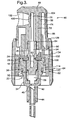
FIGURE 3 is a cross-sectional view of an upper portion of the dispenser depicted inFIGURE 1 . -
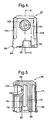
FIGURE 4 is a front elevation view of the actuator button for the dispenser ofFIGURE 1 . -
FIGURE 5 is a cross-sectional view taken along line 5-5 ofFIGURE 4 . -
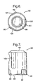
FIGURE 6 is a top plan view of the actuator button depicted inFIGURE 4 . -
FIGURE 7 is a side elevation view of the actuator button depicted inFIGURE 4 . -
FIGURE 8 is a bottom plan view of the actuator button depicted inFIGURE 4 . -
FIGURE 9 is a top plan view of an intermediate ring for the dispenser ofFIGURE 1 . -
FIGURE 10 is a side elevation view of the intermediate ring depicted inFIGURE 9 . -
FIGURE 11 is a bottom plan view of the intermediate ring depicted inFIGURE 9 . -
FIGURE 12 is a cross-sectional view taken along line 12-12 ofFIGURE 9 . -
FIGURE 13 is a top plan view of a locking ring for the dispenser shown inFIGURE 1 . -
FIGURE 14 is a side elevation view of the locking ring shown inFIGURE 13 . -
FIGURE 15 is a bottom plan view of the locking ring shown inFIGURE 13 . -
FIGURE 16 is a cross-sectional view of the locking ring taken along line 16-16 ofFIGURE 13 . - With reference to the embodiment depicted in
FIGURE 1 , adispenser 10 contains a liquid cosmetic product, which can include hair spray, body spray, deodorant, antiperspirant and fragrances such as perfume and cologne. Thedispenser 10 contains the liquid cosmetic composition under pressure, i.e. a pressure that is greater than atmospheric pressure, similar to a known aerosol container so that the liquid cosmetic product can be quickly dispensed from the dispenser. - As seen in
FIGURE 2 , thedispenser 10 can be appropriately shaped and sized so it is discretely concealed in a person's palm and can be concealed or substantially completely concealed in a closed fist. Because of the small size of thedispenser 10, it also fits conveniently into a clothing pocket. In one embodiment the dispenser has a diameter up to about 2.5 cm, more particularly, from about 1 cm to about 2.5 cm, and a height less than about 9 cm, more particularly, from about 7 cm to about 8 cm. In another embodiment the dispenser has a diameter of from about 1.5 cm to about 2 cm, and a height of from about 7 cm to about 8 cm. The hand H shown inFIGURE 2 is meant to depict a typical teenage boy's hand having a palm breadth PB of about 7 cm to about 9 cm and a first finger length of about 10 cm to about 14 cm. Thedispenser 10 is discretely concealed in the person's palm and can be dispensed quickly to cover up or eliminate embarrassing odours. For example, the first finger can be moved to allow the liquid cosmetic product to exit the dispenser and the thumb can be used to operate the dispenser. - With reference back to
FIGURE 1 , thedispenser 10 includes acontainer 12 and anactuator assembly 14. The container and the actuator assembly are attached to one another and form a single unit that is disposed or recycled once the liquid cosmetic product has been dispensed from the dispenser. - The
container 12 includes a chamber that holds the liquid cosmetic product that is to be dispensed. In the depicted embodiment, thecontainer 12 has an internal free volume of less than about 60 mL. In one embodiment, the container has an internal free volume of from about 5 mL to about 40 mL. In another embodiment, the container has an internal free volume of from about 5 mL to about 20 mL. In another embodiment the container has an internal free volume of from about 6 mL to about 15 mL, more particularly, from about 6 mL and about 10 mL. In another embodiment, the container has an internal free volume of about 8.5 mL. The container is cylindrical in shape, similar to a conventional aerosol can, but can take other configurations without departing from the scope of the invention. In the depicted embodiment, the container has a diameter of up to about about 20 mm. In another embodiment the container has a diameter of from about 10 to about 20 mm, more particularly from about 10 to about 15 mm. In yet another embodiment, the diameter is about 15 mm. Thecontainer 12 connects to and is selectively opened and closed by theactuator assembly 14. The container is cylindrical with an open top and in the depicted embodiment is made from aluminum. Other materials can be used. Where the liquid cosmetic product is to be held under pressure, the other materials should be able to withstand the pressure at which the liquid cosmetic product will be held. - With reference to
FIGURE 3 , avalve cup 18 that forms part of avalve assembly 22 connects to and covers the container (thecontainer 12 is not shown inFIGURE 3 ). Thevalve cup 18 fits onto the container and is also made of aluminum. Thevalve cup 18 has a diameter at its uppermost end that, in one embodiment, is less than about 20 mm and preferably less than about 15 mm. Thevalve cup 18 crimps on to thecontainer 16 via an external crimping action that reduces the diameter of the container and the valve cup at the crimped portion to a diameter that, in one embodiment, is from about 10 to about 12 mm, more particularly, from about 11.2 mm to about 11.7 mm. In one embodiment, the crimp depth is from about 4 to about 6 mm, more particularly from about 4.4 to about 5.3 mm. Thevalve cup 18 includes anopening 24 through which avalve stem 26 of the valve assembly extends. Thevalve assembly 22 selectively opens and closes to provide selective dispensing of the liquid cosmetic product stored in the container. - With continued reference to
FIGURE 3 , thevalve assembly 22 includes avalve stem 26 that extends through theopening 24 in thevalve cup 18. Anannular seal 28 surrounds thevalve stem 26. A biasing member, such as aspring 32, biases thevalve stem 26 upwardly (as per the orientation depicted inFIGURE 3 ) towards a closed position which is shown inFIGURE 3 . The biasingmember 32 is seated in and acts against avalve seat 34. Theannular seal 28 is pressed against an upper inner surface of thecap 18 by thevalve seat 34. A second, lowerannular seal 36 surrounds thevalve seat 34 and abuts an inner cylindrical surface of the container 12 (not depicted inFIGURE 3 ). Thecontainer 12 is sandwiched between thevalve cup 18 and thevalve seat 34 so that these components are fixed in relation to one another. Thevalve seat 34 defines avalve chamber 38 that receives thespring 32 and a lower portion of thevalve stem 26. Thevalve seat 34 also defines adip tube chamber 42 that snuggly receives adip tube 44 that extends into the container 12 (FIGURE 1 ) holding the liquid cosmetic product. Thedip tube 42 is in communication with thevalve chamber 38 via apassage 46. - To dispense product from the
container 16, thevalve stem 26 is moved towards thevalve seat 34 and acts against the biasing force of thespring 32 to open thevalve assembly 22. Aradial opening 52 formed in thevalve stem 26 is blocked by theannular seal 28 when the valve stem is biased to the closed position as shown inFIGURE 3 . When thevalve stem 26 is moved downwardly with respect to theannular seal 28, then theradial passage 52, which is in communication with anaxial passage 54, also communicates with thevalve chamber 38, which is under pressure, and the valve chamber is in communication with thedip tube 42 via thepassage 46. - The
actuator assembly 14 includes anactuator button 60 that selectively moves thevalve stem 26 to dispense the liquid cosmetic product. Theactuator assembly 14 connects to thecontainer 12 and is "capless" for quick actuation. Because the actuator assembly is capless, i.e. a cap is not removed from the dispenser prior to dispensing product, a locking mechanism is provided to inhibit accidental dispensing of the liquid cosmetic product from the dispenser. Theactuator assembly 14 in the depicted embodiment includes theactuator button 60, anintermediate ring 62 and alocking ring 64. Because of the small size the user of the dispenser can operate, lock and unlock the dispenser using only one hand if desired. In the depicted embodiment, the locking mechanism is located with respect to the actuator to facilitate one handed operation. - The
actuator button 60 is movable to move thevalve stem 26 against the biasing force of thespring 32. Theactuator button 60 in the depicted embodiment is generally cylindrical having a closed end and an open end. In the depicted embodiment the actuator button is made from a molded plastic, but other materials and methods of manufacture can be used. With reference toFIGURES 4-8 , theactuator button 60 includes a generally cylindricalouter wall 66 depending from anupper platform 68 and astem socket 72 that is radially spaced from the outer wall and depends from theupper platform 68. Anannular gap 74 is disposed between theouter wall 66 and thestem socket 72, and as seen inFIGURE 3 a portion of theintermediate ring 62 resides in thisgap 74 when theactuator assembly 14 is finally assembled and attached to thecontainer 12. - As most clearly seen in
FIGURE 3 , theactuator button 60 directly connects to thevalve stem 26. To make this connection, apassage 76 is formed in thestem socket 72. With reference back toFIGURE 5 , the passage includes alower counterbore 78 that receives thevalve stem 26 and achamfer 82 to facilitate alignment and connection of theactuator button 60 to thevalve stem 26. The valve stem 26 includes anannular protuberance 84 that radially extends from the outer cylindrical surface of thevalve stem 26 and engages with the inner cylindrical surface of thecouterbore 78. The outer diameter of thevalve stem 26 at theprotuberance 84 is slightly larger than the diameter of thecounterbore 78 to provide a friction fit between theactuator button 60 and thevalve stem 26 so that removal of theactuator button 60 from thevalve stem 26 is difficult. In making the fit, theprotuberance 84 and/or the inner surface of thecounterbore 78 can deform. Alternatively, thevalve stem 26 can be formed with an interlock feature to facilitate a secure attachment and preclude easy removal of the actuator button from the valve stem. - In the depicted embodiment, the
actuator button 60 does not easily rotate with respect to thecontainer 12. Theactuator button 60 includes a plurality of splines 86 (FIGURE 8 ) that extend from thestem socket 72 to provide the stem socket with a non-circular configuration to control the rotational movement of theactuator button 60 with respect to theintermediate ring 62 and thus thecontainer 12 in a manner that will be described in more detail below. As most clearly seen inFIGURE 8 , thesplines 86 are angularly spaced 120 degrees from one another around theinner stem socket 72. Thesplines 86 cooperate with theintermediate ring 62 in a manner that will be described in more detail below. - The
actuator button 60 also cooperates with the lockingring 64. Theactuator button 60 includesexternal tabs 90 formed on a lower (per the orientation ofFIGURE 4 ) end that extend radially outwardly from the generally cylindricalouter wall 66. As most clearly seen inFIGURE 8 , theexternal tabs 90 are angularly displaced 120 degrees apart from one another about the circumference of the outerannular wall 66. Theactuator button 60 also includes a plurality ofcutouts 92 formed in and extending upwardly from alowermost edge 94 of theannular wall 66. In the depicted embodiment, threecutouts 92 spaced 120 degrees apart from one another are formed in theactuator button 60. Eachcutout 92 terminates adjacent a respectiveexternal tab 90. - The
actuator button 60 also includes a cosmeticliquid product outlet 100 that is in communication with theinternal passage 76. In the embodiment where the dispenser is capless, theoutlet 100 is always in communication with ambient. Theoutlet passage 100 connects theinternal passage 76 to anoutlet cavity 102 that is formed in the actuator button. The depth and diameter of thecavity 102 is a function of the pressure at which the cosmetic liquid product is held in the container as well as function of the diameter of theoutlet 100. The cosmetic liquid product emanates from thefluid outlet 100 and disperses in a radial fashion outwardly from the fluid outlet. Thecavity 102 is dimensional so that little, if any, liquid cosmetic product contacts the cavity wall when being dispensed from the dispenser. Lastly, theactuator button 60 includes a plurality oflongitudinal recesses 104 that act as a type of an alignment mechanism for the locking mechanism, which will be described in more detail below. - With reference to
FIGURE 3 , theintermediate ring 62 cooperates with theactuator button 60 and the lockingring 64. With reference toFIGURE 10 , theintermediate ring 62 in the depicted embodiment is a molded plastic part having anupper section 110 and a lower section 112 (as per the orientation depicted inFIGURE 10 ). Theupper section 110 and alower section 112 are both generally cylindrical. - The
intermediate ring 62 very snugly fits to thecontainer 12 so that axial movement (with respect to a central axis of the container) is very difficult as well as rotational movement about the axis. To provide this very snug fit, thelower section 112 of theintermediate ring 62 includes an inwardly protrudingannular protuberance 114 that fits into an axially inwardly directed annular channel or indentation 120 (FIGURE 3 ) formed via the external crimp that is formed in thecontainer 12 and thevalve cup 18. The fit between theintermediate ring 62 and thecontainer 12 is such that a torque of at least about 30 N-cm is required to rotate the intermediate ring with respect to the container and a removal force of at least about 100 N is required to remove the intermediate ring from the container once it is attached to the container. This allows theintermediate ring 62 to operate as a relatively stationary component, e.g. in comparison to the lockingring 64, of the dispenser and other components, i.e. theactuator button 60 and the lockingring 64, can move with respect to the intermediate ring. - The
intermediate ring 62 also cooperates with theactuator button 60 to inhibit rotational movement of theactuator button 60 about the central axis of the container. With reference toFIGURES 9 and11 ,tracks 116 are formed in theupper section 110 of theintermediate ring 62. Thetracks 116 are angularly spaced 120 degrees apart from one another similar to the splines 86 (FIGURE 8 ) formed in theactuator button 60.Ramps 118 formed on an inner wall of theupper section 110 are sloped toward thetracks 116 for the splines 86 (FIGURE 8 ) of theactuator button 60. Theramps 118 provide an alignment feature for the insertion of the actuator button into the intermediate ring during assembly of the dispensers. - With reference to
FIGURES 13-16 , the lockingring 64 is a generally tapered annular molded piece of plastic. The lockingring 64 includes an upper inwardly extendingannular protrusion 128 that the lowerexternal tabs 90 of theactuator button 60 slide over when the locking ring is placed over the button (seeFIGURE 3 ). - The locking
ring 64 attaches to theintermediate ring 62 via a press fit. More particularly, an inwardly protrudingannular ridge 130 is pressed over an outwardly protruding annular ridge 132 (FIGURES 10 and12 ) formed at an upper end of thelower section 112 of theintermediate ring 62. With reference toFIGURES 3 and16 , achannel 134 is formed in the lockingring 64 above theannular ridge 130 that receives the outwardly extending annular ridge 132 (FIGURE 12 ) of the intermediate ring. The connection between the lockingring 64 and theintermediate ring 62 precludes axial movement (the axis being defined as the central axis of the container 12) while allowing rotational movement about the axis of the locking ring with respect to the intermediate ring. Desirably, the lockingring 64 can rotate with respect to theintermediate ring 62 upon the application of a torque of from about 2 N-cm to about 6 N-cm, which is much less than the torque required to rotate theintermediate ring 62 about thecontainer 12. The upper torque limit, i.e. about 6 N-cm, is determined to provide an ease of use. If the torque is too high, then it is difficult for an operator to rotate the lockingring 64. The lower torque limit is selected to inhibit accidental rotation, for example when the dispenser is located in one's clothing pocket. If the torque required to rotate the lockingring 64 is too low, the locking ring may have a tendency to rotate inadvertently. - A plurality of inwardly protruding
tabs 136 are provided on the lockingring 64 and cooperate with theactuator button 60 to selectively limit the axial movement of theactuator button 60 with respect to the locking ring and more particularly with respect to the container to control opening and closing thevalve assembly 22. With reference back toFIGURE 7 , thetabs 136, which are angularly spaced 120 degrees apart from one another, cooperate with the lowermost edge 94 (typically adjacent the tabs 90) of theactuator button 60 and thecutouts 92. When an upper surface of eachtab 136 contacts thelowermost edge 94 of the actuator button 60 (FIGURE 7 ), then the actuator button is precluded from moving axially with respect to thecontainer 12 and as such is "locked." When the lockingring 64 is rotated (desirably less than about 90 degrees) with respect to theintermediate ring 62, theactuator button 60 and thecontainer 12, thetabs 136 can align with thecutouts 92 in thebutton 60 to allow the button to move axially with respect to the container thus opening thevalve assembly 22, whereby thetabs 136 reside in thecutouts 92 as thebutton 60 is pressed downwardly. - In the depicted embodiment, the locking
ring 64 does not translate or move along its rotational axis. The upper edge of the lockingring 64 remains below theoutlet 100 for the dispenser when the locking ring is in both the locked and the unlocked position. Alternative embodiments may allow for translational movement along the rotational axis. -
Annular ridges 138 can be provided on an outer surface of the lockingring 64 to facilitate gripping and rotation of the locking ring.Smooth surfaces 142 can also be provided on the lockingring 64 interposed between the vertical ridges as an alignment feature to indicate whether the dispenser is in a "locked" or an "unlocked" position. Thesmooth surfaces 142 can align with thelongitudinal recesses 104 in theactuator button 60 to indicate a "locked" or "unlocked" position. - The
tabs 136 also cooperate with theintermediate ring 62 to limit the angular rotational displacement of the lockingring 64 with respect to the intermediate ring. With reference back toFIGURES 9 and10 , theintermediate ring 62 includeswings 140 extending outwardly from a cylindricalsmooth wall 142. Thewings 140 are disposed on a lower half of theupper section 110 and a smoothcylindrical wall 142 is provided on the upper half. Thewings 140 provide afirst contact surface 144 against which the tabs 136 (FIGURE 13 ) on the locking ring contact when the locking ring is rotated with respect to the intermediate ring. Asecond contact surface 146 that is angularly spaced from the first contact surface is also found on theupper section 110 of the intermediate ring. The tabs 136 (FIGURE 13 ) of the lockingring 64 move between the contact surfaces 144 and 146. When thetabs 136 contact thecontact surface 144, the dispenser is in the "locked" position. When thetabs 136 contact thesecond contact surface 146, the dispenser is in the "unlocked" position. - With reference to
FIGURE 9 , bumps 150 and 152 are disposed between a set of contact surfaces 144 and 146. Thebumps tabs 136 and the locking ring to provide an indexing and/or locking feature to allow the user of the dispenser to know the state, e.g. locked or unlocked, in which the dispenser is disposed. Thetabs 136 ride over thebumps - A liquid cosmetic product dispenser has been described with reference to certain embodiments. The liquid cosmetic product dispenser can dispense all sorts of liquid cosmetic products, including, hair spray, body spray, antiperspirant, deodorant, perfume, cologne, as well as other products that are typically dispensed via an aerosol can. Many available alterations may occur to those skilled in the art upon reading the preceding detailed description. The invention is not intended to be limited solely to those embodiments described above, but is intended to include any device that comes within the scope of the appended claims.
Claims (8)
- A palm-sized dispenser (10) comprising an outlet (100), a movable actuator button (60) and a locking ring (64) rotatable between a locked and an unlocked position, the locking ring (64) including internal tabs (136) that contact the actuator button (60) in the locked position to limit movement of the actuator button (60) in a first axis, an upper edge of the locking ring (64) being disposed below the outlet (100) when in the locked position, the internal tabs (136) riding over bumps (150 and 152) located between contact surfaces (144 and 146) on an intermediate ring (62) to provide an interference or snap fit, the dispenser (10) further comprising a valve cup (18) crimped externally onto a container (12) for a liquid cosmetic product to be dispensed, characterized in that the intermediate ring (62) is connected to the locking ring (64) and to the actuator button (60) in a manner such that the actuator button (60) does not rotate with respect to the intermediate ring (62), said intermediate ring (62) fitting very snugly to the container (12) by means of the lower section (112) of the intermediate ring (62) including an inwardly protruding annular protuberance (114) that fits into an axially inwardly directed annular channel or indentation formed via the external crimp formed in the container (12) and the and the valve cup (18).
- The dispenser (10) of claim 1, further comprising valve assembly (22) for selectively dispensing product, the valve assembly (22) including a valve cup (18) including an opening (24) and a valve stem (26) disposed in the opening (24), the valve stem (26) including a protuberance (114) and the actuator button (60) including a passage (46) that receives the valve stem (26) and at least one of the protuberance and an inner surface of the passage (46) deforms to connect the actuator button (60) to the valve stem (26).
- The dispenser (10) of claim 1, comprising:The container (12) which isa rigid container (12) defining a chamber and an outlet in communication with the chamber, the container (12) being less than about 9 cm in height and less than about 2 cm in diameter;a liquid cosmetic product in the container (12), the product being under pressure exceeding atmospheric pressure;a valve assembly (22) connected to the container (12) for selectively opening and closing a passage (46) in communication with the outlet (100) to allow for the selective discharge of the product from the container (12), the valve assembly (22) including a valve stem (26) moveable between an open position, which allows the product to exit the chamber, and a closed position, which precludes the product from exiting the chamber; in which theactuator (60) is connected to the valve stem (26), the actuator (60) being selectively moveable in the first axis between a first position, which moves the valve stem (26) into the open position, and a second position, which allows the valve stem (26) to move into the second position, and the actuator (60) further including the outlet (100) opening in communication with the passage (46), the outlet opening (100) being uncovered no matter the location of other components of the device.
- The dispenser (10) of claim 3, wherein an upper edge of the locking ring (64) is disposed below the outlet (100) opening in the first position and the second position.
- The dispenser (10) of claim 3 or 4 being configured to be at least partially concealed in a closed fist of a hand having a palm breadth of between about 7 cm to about 9 cm and a first finger length of about 10 cm to about 14 cm.
- The dispenser (10) of any of claims 3 to 5, wherein the intermediate ring (62) is connected to the container (12) and the locking ring (64) is connected to the intermediate ring (62) for rotational movement with respect to the intermediate ring (62).
- The dispenser (10) of claim 6, wherein a torque required to rotate the intermediate ring (62) with respect to the container (12) is at least about 30 N-cm.
- The dispenser (10) of claim 7, wherein the torque required to rotate the locking ring (64) is from about 2 N-cm to about 6 N-cm.
Applications Claiming Priority (3)
| Application Number | Priority Date | Filing Date | Title |
|---|---|---|---|
| US88617507P | 2007-01-23 | 2007-01-23 | |
| US11/625,992 US7686189B2 (en) | 2007-01-23 | 2007-01-23 | Pocket sized fluid dispenser |
| PCT/EP2008/050569 WO2008090093A1 (en) | 2007-01-23 | 2008-01-18 | Pocket sized fluid dispenser |
Publications (2)
| Publication Number | Publication Date |
|---|---|
| EP2114796A1 EP2114796A1 (en) | 2009-11-11 |
| EP2114796B1 true EP2114796B1 (en) | 2013-03-06 |
Family
ID=44279779
Family Applications (1)
| Application Number | Title | Priority Date | Filing Date |
|---|---|---|---|
| EP08701578A Not-in-force EP2114796B1 (en) | 2007-01-23 | 2008-01-18 | Pocket sized fluid dispenser |
Country Status (10)
| Country | Link |
|---|---|
| US (2) | US7686189B2 (en) |
| EP (1) | EP2114796B1 (en) |
| JP (1) | JP2010516363A (en) |
| CN (1) | CN101641267A (en) |
| AR (2) | AR064980A1 (en) |
| AU (1) | AU2008208896A1 (en) |
| CA (1) | CA2676398A1 (en) |
| EA (1) | EA200970703A1 (en) |
| MX (1) | MX2009007879A (en) |
| WO (3) | WO2008089875A1 (en) |
Families Citing this family (19)
| Publication number | Priority date | Publication date | Assignee | Title |
|---|---|---|---|---|
| US7677420B1 (en) | 2004-07-02 | 2010-03-16 | Homax Products, Inc. | Aerosol spray texture apparatus for a particulate containing material |
| US7487893B1 (en) | 2004-10-08 | 2009-02-10 | Homax Products, Inc. | Aerosol systems and methods for dispensing texture material |
| DE102005014397A1 (en) * | 2005-03-24 | 2006-09-28 | Wella Ag | spray applicator |
| US7686189B2 (en) * | 2007-01-23 | 2010-03-30 | Conopco, Inc. | Pocket sized fluid dispenser |
| US10221405B2 (en) | 2008-11-20 | 2019-03-05 | Novozymes, Inc. | Polypeptides having amylolytic enhancing activity and polynucleotides encoding same |
| US9506046B2 (en) | 2008-11-20 | 2016-11-29 | Novozymes, Inc. | Polypeptides having amylolytic enhancing activity and polynucleotides encoding same |
| FR2961189B1 (en) * | 2010-06-14 | 2013-02-22 | Valois Sas | HEAD OF DISTRIBUTION OF FLUID PRODUCT. |
| EP2597055B1 (en) * | 2010-07-20 | 2015-09-16 | Toyo Aerosol Industry Co., Ltd. | Multiple fluid dispensing aerosol device |
| US9248457B2 (en) | 2011-07-29 | 2016-02-02 | Homax Products, Inc. | Systems and methods for dispensing texture material using dual flow adjustment |
| US9156042B2 (en) | 2011-07-29 | 2015-10-13 | Homax Products, Inc. | Systems and methods for dispensing texture material using dual flow adjustment |
| ES2532532T3 (en) | 2011-12-22 | 2015-03-27 | Unilever N.V. | Spray head for a spray device |
| US9156602B1 (en) | 2012-05-17 | 2015-10-13 | Homax Products, Inc. | Actuators for dispensers for texture material |
| US9435120B2 (en) | 2013-03-13 | 2016-09-06 | Homax Products, Inc. | Acoustic ceiling popcorn texture materials, systems, and methods |
| CA2859537C (en) | 2013-08-19 | 2019-10-29 | Homax Products, Inc. | Ceiling texture materials, systems, and methods |
| USD787326S1 (en) | 2014-12-09 | 2017-05-23 | Ppg Architectural Finishes, Inc. | Cap with actuator |
| US10835913B2 (en) * | 2018-04-04 | 2020-11-17 | Jens Martin Mispel-Beyer | Refillable vertical foregrip spray device |
| US20200069553A1 (en) * | 2018-08-31 | 2020-03-05 | Honeywell International Inc. | Personal care spray compositions and methods comprising trans-1-chloro-3,3,3-trifluoropropene |
| US20220331212A1 (en) * | 2019-08-28 | 2022-10-20 | Honeywell International Inc. | NON-FLAMMABLE, DRY PERSONAL CARE PRODUCT CONTAINING trans-1233zd AND ETHANOL |
| CN111096534B (en) * | 2019-12-30 | 2023-09-15 | 浙江正庄实业有限公司 | Antibacterial polymer strong-pressure single-layer vacuum bottle and its material preparation method |
Family Cites Families (35)
| Publication number | Priority date | Publication date | Assignee | Title |
|---|---|---|---|---|
| GB1155329A (en) * | 1967-01-06 | 1969-06-18 | Philip Meshberg | Nozzle Wiping Device for a Pressurized Material Dispenser. |
| US3426948A (en) * | 1967-03-01 | 1969-02-11 | Pittsburgh Railways Co | Foam actuator |
| US3782605A (en) * | 1972-12-18 | 1974-01-01 | Scovill Manufacturing Co | Childproof aerosol actuator consisting of two members, operative by relatively rotating the two members |
| JPS50121817A (en) | 1974-03-12 | 1975-09-25 | ||
| US4220263B1 (en) * | 1975-08-29 | 1997-07-22 | Katz W Simon | Combined holder for keys and protective spray |
| US4277004A (en) * | 1979-10-15 | 1981-07-07 | Barlics John J | Cover and aerosol activator for aerosol spray can |
| IT8023428U1 (en) | 1980-11-19 | 1982-05-19 | S P A Valvole Aerosol Res Italiana Vari | Structure of a metering valve for the dispensing of liquids under pressure |
| US4454966A (en) * | 1981-11-27 | 1984-06-19 | Hicks Sonja L | Aerosol dispenser case |
| US4735349A (en) * | 1982-02-04 | 1988-04-05 | Diamond Aerosol Corporation | Irritant aerosol spray |
| US4477005A (en) * | 1982-06-11 | 1984-10-16 | Louie Martinez | Portable, hand-mountable defense weapon system |
| FR2532714A1 (en) * | 1982-09-06 | 1984-03-09 | Aerosol Inventions Dev | Elastomer seal for aerosol contg. solvent |
| FR2569581B1 (en) | 1984-08-28 | 1987-07-17 | Oreal | VAPORIZER WITH FLOW ADJUSTMENT DEVICE |
| US5070611A (en) * | 1990-11-27 | 1991-12-10 | Stephen Derin | Razor and dispenser |
| US5088121A (en) * | 1991-01-29 | 1992-02-18 | Wallace Jacqueline E | Glove with a pocket for holding Mace and a method of making same |
| WO1993015845A1 (en) * | 1992-02-07 | 1993-08-19 | The Procter & Gamble Company | Spray pump package employing multiple orifices for dispensing liquid in different spray patterns with automatically adjusted optimized pump stroke for each pattern |
| US5649645A (en) * | 1995-02-15 | 1997-07-22 | S. C. Johnson & Son, Inc. | Overcap sprayer assembly |
| GB2307278B (en) * | 1995-11-16 | 1999-01-20 | Bespak Plc | Improved seal arrangements for pressurised dispensing containers |
| US5839624A (en) * | 1996-04-16 | 1998-11-24 | Armament Systems And Procedures, Inc. | Horizontal release aerosol canister |
| JPH10157750A (en) * | 1996-10-02 | 1998-06-16 | Taisei Kako Kk | Extruded metal tube and aerosol can, and method of manufacturing extruded metal tube |
| WO1999016684A1 (en) * | 1997-10-01 | 1999-04-08 | Osaka Shipbuilding Co., Ltd. | Double pressurized container for charging undercup and double pressurized products using the container |
| GB9727366D0 (en) * | 1997-12-24 | 1998-02-25 | Unilever Plc | Sprayhead |
| US6283337B1 (en) * | 1998-12-21 | 2001-09-04 | Kao Corporation | Aerosol container |
| DE19927381A1 (en) * | 1999-05-04 | 2000-11-16 | Thomas Gmbh | Multi-purpose spray can has fixed end-stop allowing for a wider range of cap and spray head designs |
| JP4321930B2 (en) | 1999-12-08 | 2009-08-26 | 株式会社三谷バルブ | Ejector |
| JP3970739B2 (en) | 2002-09-30 | 2007-09-05 | 株式会社吉野工業所 | Foot spray container |
| US6986207B2 (en) * | 2003-01-24 | 2006-01-17 | Ali Saban Selek | Single-use disposable shaving set |
| JP4471972B2 (en) * | 2003-03-03 | 2010-06-02 | シークウィスト パーフェクト ディスペンスイング フォーリン, インコーポレイテッド | Aerosol actuator |
| TWD106727S1 (en) | 2004-03-31 | 2005-10-01 | 久光製藥股份有限公司 | Packaging sprayer |
| US7249692B2 (en) * | 2004-11-29 | 2007-07-31 | Seaquistperfect Dispensing Foreign, Inc. | Dispenser with lock |
| USD541170S1 (en) | 2005-03-23 | 2007-04-24 | Rexam Dispensing Systems | Spray bottle |
| PL1749759T3 (en) | 2005-08-05 | 2010-01-29 | Unilever Nv | Spray tip dispensing tip |
| US7922041B2 (en) * | 2005-12-29 | 2011-04-12 | The Procter & Gamble Company | Spray dispensers |
| USD559702S1 (en) * | 2007-01-23 | 2008-01-15 | Conopco, Inc. | Dispenser |
| US7686189B2 (en) * | 2007-01-23 | 2010-03-30 | Conopco, Inc. | Pocket sized fluid dispenser |
| USD574706S1 (en) * | 2007-01-23 | 2008-08-12 | Conopco, Inc. | Part of dispenser |
-
2007
- 2007-01-23 US US11/625,992 patent/US7686189B2/en not_active Expired - Fee Related
- 2007-12-19 WO PCT/EP2007/064273 patent/WO2008089875A1/en not_active Ceased
-
2008
- 2008-01-18 CA CA002676398A patent/CA2676398A1/en not_active Abandoned
- 2008-01-18 EP EP08701578A patent/EP2114796B1/en not_active Not-in-force
- 2008-01-18 WO PCT/EP2008/050569 patent/WO2008090093A1/en not_active Ceased
- 2008-01-18 EA EA200970703A patent/EA200970703A1/en unknown
- 2008-01-18 CN CN200880009426A patent/CN101641267A/en active Pending
- 2008-01-18 WO PCT/EP2008/050568 patent/WO2008090092A1/en not_active Ceased
- 2008-01-18 AU AU2008208896A patent/AU2008208896A1/en not_active Abandoned
- 2008-01-18 MX MX2009007879A patent/MX2009007879A/en unknown
- 2008-01-18 JP JP2009546720A patent/JP2010516363A/en not_active Withdrawn
- 2008-01-22 AR ARP080100255A patent/AR064980A1/en unknown
- 2008-01-22 AR ARP080100256A patent/AR064981A1/en unknown
- 2008-01-23 US US12/009,883 patent/US7748572B2/en not_active Expired - Fee Related
Also Published As
| Publication number | Publication date |
|---|---|
| AR064980A1 (en) | 2009-05-06 |
| WO2008090092A1 (en) | 2008-07-31 |
| JP2010516363A (en) | 2010-05-20 |
| EA200970703A1 (en) | 2010-02-26 |
| US7686189B2 (en) | 2010-03-30 |
| US20080173675A1 (en) | 2008-07-24 |
| US7748572B2 (en) | 2010-07-06 |
| CA2676398A1 (en) | 2008-07-31 |
| WO2008090093A1 (en) | 2008-07-31 |
| AU2008208896A1 (en) | 2008-07-31 |
| US20080173676A1 (en) | 2008-07-24 |
| WO2008089875A1 (en) | 2008-07-31 |
| MX2009007879A (en) | 2009-08-18 |
| EP2114796A1 (en) | 2009-11-11 |
| AR064981A1 (en) | 2009-05-06 |
| CN101641267A (en) | 2010-02-03 |
Similar Documents
| Publication | Publication Date | Title |
|---|---|---|
| US7686189B2 (en) | Pocket sized fluid dispenser | |
| US8608031B2 (en) | Lockable dispensing head | |
| US7044341B2 (en) | Device for packaging and dispensing a product, such as a cosmetic product | |
| US6398082B2 (en) | Actuator mechanism | |
| US4572410A (en) | Safety actuator for an aerosol valve | |
| EP2342147B1 (en) | Hand held aerosol dispenser | |
| US20030071080A1 (en) | Variable flow rate valve and container equipped therewith | |
| US5255823A (en) | Actuator and cap for a fluid dispenser | |
| US9211994B2 (en) | Shroud and dispensing system for a handheld container | |
| US7364055B2 (en) | Variable-flow tilt valve and container fitted with such a valve | |
| US20040222245A1 (en) | Spraying cap | |
| US6983865B2 (en) | Fluid dispenser device | |
| EP2552805A1 (en) | Dual activated actuator cap | |
| JP2002238658A (en) | Equipment for storing and distributing products under pressure | |
| CA2097281C (en) | Pump actuator | |
| WO2017153440A1 (en) | Dispenser pumps | |
| US20020020721A1 (en) | Dispenser and method for dispensing a product under pressure | |
| JP4523811B2 (en) | Device for discharging the contents of aerosol containers | |
| JP4672178B2 (en) | Pushbutton for aerosol container | |
| JP4789643B2 (en) | Residual content discharge device for aerosol container | |
| JP3892929B2 (en) | Pushbutton for aerosol container | |
| JP4339501B2 (en) | Aero pushbutton | |
| BRPI0806399A2 (en) | palm size dispenser and lidless aerosol dispenser | |
| JP2006069629A (en) | Content discharge device of aerosol container |
Legal Events
| Date | Code | Title | Description |
|---|---|---|---|
| PUAI | Public reference made under article 153(3) epc to a published international application that has entered the european phase |
Free format text: ORIGINAL CODE: 0009012 |
|
| 17P | Request for examination filed |
Effective date: 20090720 |
|
| AK | Designated contracting states |
Kind code of ref document: A1 Designated state(s): AT BE BG CH CY CZ DE DK EE ES FI FR GB GR HR HU IE IS IT LI LT LU LV MC MT NL NO PL PT RO SE SI SK TR |
|
| DAX | Request for extension of the european patent (deleted) | ||
| 17Q | First examination report despatched |
Effective date: 20100712 |
|
| GRAP | Despatch of communication of intention to grant a patent |
Free format text: ORIGINAL CODE: EPIDOSNIGR1 |
|
| GRAS | Grant fee paid |
Free format text: ORIGINAL CODE: EPIDOSNIGR3 |
|
| GRAA | (expected) grant |
Free format text: ORIGINAL CODE: 0009210 |
|
| AK | Designated contracting states |
Kind code of ref document: B1 Designated state(s): AT BE BG CH CY CZ DE DK EE ES FI FR GB GR HR HU IE IS IT LI LT LU LV MC MT NL NO PL PT RO SE SI SK TR |
|
| REG | Reference to a national code |
Ref country code: GB Ref legal event code: FG4D |
|
| REG | Reference to a national code |
Ref country code: AT Ref legal event code: REF Ref document number: 599475 Country of ref document: AT Kind code of ref document: T Effective date: 20130315 Ref country code: CH Ref legal event code: EP |
|
| REG | Reference to a national code |
Ref country code: IE Ref legal event code: FG4D |
|
| REG | Reference to a national code |
Ref country code: DE Ref legal event code: R096 Ref document number: 602008022687 Country of ref document: DE Effective date: 20130502 |
|
| REG | Reference to a national code |
Ref country code: AT Ref legal event code: MK05 Ref document number: 599475 Country of ref document: AT Kind code of ref document: T Effective date: 20130306 |
|
| PG25 | Lapsed in a contracting state [announced via postgrant information from national office to epo] |
Ref country code: BG Free format text: LAPSE BECAUSE OF FAILURE TO SUBMIT A TRANSLATION OF THE DESCRIPTION OR TO PAY THE FEE WITHIN THE PRESCRIBED TIME-LIMIT Effective date: 20130606 Ref country code: AT Free format text: LAPSE BECAUSE OF FAILURE TO SUBMIT A TRANSLATION OF THE DESCRIPTION OR TO PAY THE FEE WITHIN THE PRESCRIBED TIME-LIMIT Effective date: 20130306 Ref country code: ES Free format text: LAPSE BECAUSE OF FAILURE TO SUBMIT A TRANSLATION OF THE DESCRIPTION OR TO PAY THE FEE WITHIN THE PRESCRIBED TIME-LIMIT Effective date: 20130617 Ref country code: LT Free format text: LAPSE BECAUSE OF FAILURE TO SUBMIT A TRANSLATION OF THE DESCRIPTION OR TO PAY THE FEE WITHIN THE PRESCRIBED TIME-LIMIT Effective date: 20130306 Ref country code: NO Free format text: LAPSE BECAUSE OF FAILURE TO SUBMIT A TRANSLATION OF THE DESCRIPTION OR TO PAY THE FEE WITHIN THE PRESCRIBED TIME-LIMIT Effective date: 20130606 Ref country code: SE Free format text: LAPSE BECAUSE OF FAILURE TO SUBMIT A TRANSLATION OF THE DESCRIPTION OR TO PAY THE FEE WITHIN THE PRESCRIBED TIME-LIMIT Effective date: 20130306 |
|
| REG | Reference to a national code |
Ref country code: NL Ref legal event code: VDEP Effective date: 20130306 |
|
| REG | Reference to a national code |
Ref country code: LT Ref legal event code: MG4D |
|
| PG25 | Lapsed in a contracting state [announced via postgrant information from national office to epo] |
Ref country code: FI Free format text: LAPSE BECAUSE OF FAILURE TO SUBMIT A TRANSLATION OF THE DESCRIPTION OR TO PAY THE FEE WITHIN THE PRESCRIBED TIME-LIMIT Effective date: 20130306 Ref country code: LV Free format text: LAPSE BECAUSE OF FAILURE TO SUBMIT A TRANSLATION OF THE DESCRIPTION OR TO PAY THE FEE WITHIN THE PRESCRIBED TIME-LIMIT Effective date: 20130306 Ref country code: SI Free format text: LAPSE BECAUSE OF FAILURE TO SUBMIT A TRANSLATION OF THE DESCRIPTION OR TO PAY THE FEE WITHIN THE PRESCRIBED TIME-LIMIT Effective date: 20130306 Ref country code: GR Free format text: LAPSE BECAUSE OF FAILURE TO SUBMIT A TRANSLATION OF THE DESCRIPTION OR TO PAY THE FEE WITHIN THE PRESCRIBED TIME-LIMIT Effective date: 20130607 |
|
| PG25 | Lapsed in a contracting state [announced via postgrant information from national office to epo] |
Ref country code: HR Free format text: LAPSE BECAUSE OF FAILURE TO SUBMIT A TRANSLATION OF THE DESCRIPTION OR TO PAY THE FEE WITHIN THE PRESCRIBED TIME-LIMIT Effective date: 20130306 Ref country code: BE Free format text: LAPSE BECAUSE OF FAILURE TO SUBMIT A TRANSLATION OF THE DESCRIPTION OR TO PAY THE FEE WITHIN THE PRESCRIBED TIME-LIMIT Effective date: 20130306 |
|
| PG25 | Lapsed in a contracting state [announced via postgrant information from national office to epo] |
Ref country code: PT Free format text: LAPSE BECAUSE OF FAILURE TO SUBMIT A TRANSLATION OF THE DESCRIPTION OR TO PAY THE FEE WITHIN THE PRESCRIBED TIME-LIMIT Effective date: 20130708 Ref country code: CZ Free format text: LAPSE BECAUSE OF FAILURE TO SUBMIT A TRANSLATION OF THE DESCRIPTION OR TO PAY THE FEE WITHIN THE PRESCRIBED TIME-LIMIT Effective date: 20130306 Ref country code: RO Free format text: LAPSE BECAUSE OF FAILURE TO SUBMIT A TRANSLATION OF THE DESCRIPTION OR TO PAY THE FEE WITHIN THE PRESCRIBED TIME-LIMIT Effective date: 20130306 Ref country code: IS Free format text: LAPSE BECAUSE OF FAILURE TO SUBMIT A TRANSLATION OF THE DESCRIPTION OR TO PAY THE FEE WITHIN THE PRESCRIBED TIME-LIMIT Effective date: 20130706 Ref country code: SK Free format text: LAPSE BECAUSE OF FAILURE TO SUBMIT A TRANSLATION OF THE DESCRIPTION OR TO PAY THE FEE WITHIN THE PRESCRIBED TIME-LIMIT Effective date: 20130306 Ref country code: EE Free format text: LAPSE BECAUSE OF FAILURE TO SUBMIT A TRANSLATION OF THE DESCRIPTION OR TO PAY THE FEE WITHIN THE PRESCRIBED TIME-LIMIT Effective date: 20130306 Ref country code: NL Free format text: LAPSE BECAUSE OF FAILURE TO SUBMIT A TRANSLATION OF THE DESCRIPTION OR TO PAY THE FEE WITHIN THE PRESCRIBED TIME-LIMIT Effective date: 20130306 |
|
| PG25 | Lapsed in a contracting state [announced via postgrant information from national office to epo] |
Ref country code: CY Free format text: LAPSE BECAUSE OF FAILURE TO SUBMIT A TRANSLATION OF THE DESCRIPTION OR TO PAY THE FEE WITHIN THE PRESCRIBED TIME-LIMIT Effective date: 20130306 Ref country code: PL Free format text: LAPSE BECAUSE OF FAILURE TO SUBMIT A TRANSLATION OF THE DESCRIPTION OR TO PAY THE FEE WITHIN THE PRESCRIBED TIME-LIMIT Effective date: 20130306 |
|
| PLBE | No opposition filed within time limit |
Free format text: ORIGINAL CODE: 0009261 |
|
| STAA | Information on the status of an ep patent application or granted ep patent |
Free format text: STATUS: NO OPPOSITION FILED WITHIN TIME LIMIT |
|
| PG25 | Lapsed in a contracting state [announced via postgrant information from national office to epo] |
Ref country code: DK Free format text: LAPSE BECAUSE OF FAILURE TO SUBMIT A TRANSLATION OF THE DESCRIPTION OR TO PAY THE FEE WITHIN THE PRESCRIBED TIME-LIMIT Effective date: 20130306 |
|
| 26N | No opposition filed |
Effective date: 20131209 |
|
| PG25 | Lapsed in a contracting state [announced via postgrant information from national office to epo] |
Ref country code: IT Free format text: LAPSE BECAUSE OF FAILURE TO SUBMIT A TRANSLATION OF THE DESCRIPTION OR TO PAY THE FEE WITHIN THE PRESCRIBED TIME-LIMIT Effective date: 20130306 |
|
| REG | Reference to a national code |
Ref country code: DE Ref legal event code: R097 Ref document number: 602008022687 Country of ref document: DE Effective date: 20131209 |
|
| PG25 | Lapsed in a contracting state [announced via postgrant information from national office to epo] |
Ref country code: LU Free format text: LAPSE BECAUSE OF FAILURE TO SUBMIT A TRANSLATION OF THE DESCRIPTION OR TO PAY THE FEE WITHIN THE PRESCRIBED TIME-LIMIT Effective date: 20140118 Ref country code: MC Free format text: LAPSE BECAUSE OF FAILURE TO SUBMIT A TRANSLATION OF THE DESCRIPTION OR TO PAY THE FEE WITHIN THE PRESCRIBED TIME-LIMIT Effective date: 20130306 |
|
| REG | Reference to a national code |
Ref country code: CH Ref legal event code: PL |
|
| PG25 | Lapsed in a contracting state [announced via postgrant information from national office to epo] |
Ref country code: CH Free format text: LAPSE BECAUSE OF NON-PAYMENT OF DUE FEES Effective date: 20140131 Ref country code: LI Free format text: LAPSE BECAUSE OF NON-PAYMENT OF DUE FEES Effective date: 20140131 |
|
| REG | Reference to a national code |
Ref country code: IE Ref legal event code: MM4A |
|
| PG25 | Lapsed in a contracting state [announced via postgrant information from national office to epo] |
Ref country code: IE Free format text: LAPSE BECAUSE OF NON-PAYMENT OF DUE FEES Effective date: 20140118 |
|
| REG | Reference to a national code |
Ref country code: FR Ref legal event code: PLFP Year of fee payment: 9 |
|
| PG25 | Lapsed in a contracting state [announced via postgrant information from national office to epo] |
Ref country code: MT Free format text: LAPSE BECAUSE OF FAILURE TO SUBMIT A TRANSLATION OF THE DESCRIPTION OR TO PAY THE FEE WITHIN THE PRESCRIBED TIME-LIMIT Effective date: 20130306 |
|
| PG25 | Lapsed in a contracting state [announced via postgrant information from national office to epo] |
Ref country code: HU Free format text: LAPSE BECAUSE OF FAILURE TO SUBMIT A TRANSLATION OF THE DESCRIPTION OR TO PAY THE FEE WITHIN THE PRESCRIBED TIME-LIMIT; INVALID AB INITIO Effective date: 20080118 Ref country code: TR Free format text: LAPSE BECAUSE OF FAILURE TO SUBMIT A TRANSLATION OF THE DESCRIPTION OR TO PAY THE FEE WITHIN THE PRESCRIBED TIME-LIMIT Effective date: 20130306 |
|
| REG | Reference to a national code |
Ref country code: FR Ref legal event code: PLFP Year of fee payment: 10 |
|
| REG | Reference to a national code |
Ref country code: FR Ref legal event code: PLFP Year of fee payment: 11 |
|
| PGFP | Annual fee paid to national office [announced via postgrant information from national office to epo] |
Ref country code: DE Payment date: 20200121 Year of fee payment: 13 Ref country code: GB Payment date: 20200124 Year of fee payment: 13 |
|
| PGFP | Annual fee paid to national office [announced via postgrant information from national office to epo] |
Ref country code: FR Payment date: 20200121 Year of fee payment: 13 |
|
| REG | Reference to a national code |
Ref country code: DE Ref legal event code: R119 Ref document number: 602008022687 Country of ref document: DE |
|
| GBPC | Gb: european patent ceased through non-payment of renewal fee |
Effective date: 20210118 |
|
| PG25 | Lapsed in a contracting state [announced via postgrant information from national office to epo] |
Ref country code: FR Free format text: LAPSE BECAUSE OF NON-PAYMENT OF DUE FEES Effective date: 20210131 |
|
| PG25 | Lapsed in a contracting state [announced via postgrant information from national office to epo] |
Ref country code: GB Free format text: LAPSE BECAUSE OF NON-PAYMENT OF DUE FEES Effective date: 20210118 Ref country code: DE Free format text: LAPSE BECAUSE OF NON-PAYMENT OF DUE FEES Effective date: 20210803 |